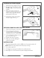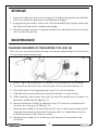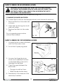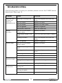
1
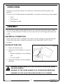
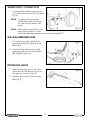
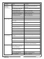
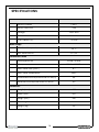
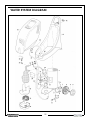
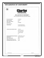
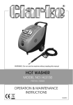
HOT WASHER
MODEL NO: KING 145
PART NO: 7320165
OPERATION & MAINTENANCE
INSTRUCTIONS
LS0709
INTRODUCTION
Thank you for purchasing this CLARKE Hot Washer.
This machine is a portable, high pressure power washer, designed for DIY and
light commercial use only.
It comprises an electric motor, a pump, a high pressure hose with a trigger and
lance, and an adaptor for injecting foam or cleaning agents into the water
jet. Additionally, a burner is incorporated to provide hot water when required
for hot washing.
Before attempting to use this product, please read this manual thoroughly and
follow the instructions carefully. In doing so you will ensure the safety of yourself
and that of others around you, and you can look forward to your purchase
giving you long and satisfactory service.
GUARANTEE
This product is guaranteed against faulty manufacture for a period of 12
months from the date of purchase. Please keep your receipt which will be
required as proof of purchase.
This guarantee is invalid if the product is found to have been abused or
tampered with in any way, or not used for the purpose for which it was
intended.
Faulty goods should be returned to their place of purchase, no product can
be returned to us without prior permission.
This guarantee does not effect your statutory rights.
2
TABLE OF CONTENTS
INTRODUCTION . . . . . . . . . . . . . . . . . . . . . . . . . . . . . . . . 2
GUARANTEE . . . . . . . . . . . . . . . . . . . . . . . . . . . . . . . . . . . 2
TABLE OF CONTENTS . . . . . . . . . . . . . . . . . . . . . . . . . . . . 3
GENERAL SAFETY RULES . . . . . . . . . . . . . . . . . . . . . . . . . 4
SAFETY SYMBOLS . . . . . . . . . . . . . . . . . . . . . . . . . . . . . . . 5
ELECTRICAL CONNECTIONS . . . . . . . . . . . . . . . . . . . . . . 6
OVERVIEW . . . . . . . . . . . . . . . . . . . . . . . . . . . . . . . . . . . . 7
UNPACKING . . . . . . . . . . . . . . . . . . . . . . . . . . . . . . . . . . 8
ASSEMBLY . . . . . . . . . . . . . . . . . . . . . . . . . . . . . . . . . . . . 8
USING YOUR POWER WASHER . . . . . . . . . . . . . . . . . . . . 10
STORAGE . . . . . . . . . . . . . . . . . . . . . . . . . . . . . . . . . . . . . 13
MAINTENANCE . . . . . . . . . . . . . . . . . . . . . . . . . . . . . . . . 13
PARTS AND SERVICING . . . . . . . . . . . . . . . . . . . . . . . . . . 15
TROUBLESHOOTING . . . . . . . . . . . . . . . . . . . . . . . . . . . . . 16
SPECIFICATIONS . . . . . . . . . . . . . . . . . . . . . . . . . . . . . . . 18
WATER SYSTEM DIAGRAM. . . . . . . . . . . . . . . . . . . . . . . . 19
KITS AND ACCESSORIES . . . . . . . . . . . . . . . . . . . . . . . . . 20
PARTS LIST. . . . . . . . . . . . . . . . . . . . . . . . . . . . . . . . . . . . . 21
DECLARATION OF CONFORMITY . . . . . . . . . . . . . . . . . . 22
3
GENERAL SAFETY RULES
WARNING: Water at high pressure can be dangerous and can cause
damage to persons or property if the operator is careless. Never allow
anyone to operate this equipment unless they are thoroughly reliable,
and familiar with the safety precautions.
1. It is important to read all parts of this operator's manual carefully before
using the power washer.
2. NEVER direct the spray towards any person or animal.
3. NEVER direct the spray towards electrical wiring or equipment.
4. NEVER hold your finger over the high pressure nozzle.
5. ALWAYS remember that the exhaust, exhaust gases and the metal lance
can get very hot during use.
6. NEVER allow children to use this machine.
7. NEVER operate the machine with any of the covers removed.
8. NEVER attempt any repairs to this machine. Always refer to a qualified
service agent.
9. NEVER supply any liquid other than water to the water inlet.
10. NEVER use the detergent bottle to spray solvents, e.g. paint thinners, petrol,
oil etc.
11. ALWAYS release any residual pressure in the system by turning off the water
supply and operating the trigger before disconnecting any hose or
accessory.
12. NEVER disconnect the plug by pulling on the power supply cable, and
never move the power washer by pulling on the high pressure hose.
13. ALWAYS keep the machine itself dry and well clear of water spray.
14. ALWAYS wear protective clothing and safety glasses. Loose particles and
other debris may be propelled at high speed by the water jet.
15. ALWAYS grip the gun firmly before pressing the trigger, expect the gun to
‘kick’ when starting.
16. ALWAYS respect the requirements of the local water company. Power
washers may only be connected to the mains drinking water supply, if a
backflow preventer valve is installed in the supply hose.
17. When not in use, ALWAYS disconnect from the water supply, and ensure the
system is completely drained. Store in a cool dry location.
4
SAFETY SYMBOLS
WARNING: Risk of electrocution.
NEVER direct spray at persons or
animals.
NEVER direct spray toward any
electrical device or electrical
outlet.
Guaranteed sound power level .
WARNING: Hot surface / Exhaust gasses.
5
ELECTRICAL CONNECTIONS
WARNING! Read these electrical safety instructions thoroughly
before connecting the product to the mains supply.
Before switching the product on, make sure that the voltage of your electricity supply is
the same as that indicated on the rating plate. This product is designed to operate on
230VAC 50Hz. Connecting it to any other power supply may cause damage.
This product may be fitted with a non-rewireable plug. If it is necessary to change the
fuse in the plug, the fuse cover must be refitted. If the fuse cover becomes lost or
damaged, the plug must not be used until a suitable replacement is obtained.
If the plug has to be changed because it is not suitable for your socket, or due to
damage, it should be cut off and a replacement fitted, following the wiring instructions
shown below. The old plug must be disposed of safely, as insertion into a mains socket
could cause an electrical hazard.
WARNING! The wires in the power cable of this product are
coloured in accordance with the following code:
Blue = Neutral
Brown = Live Yellow and Green = Earth
If the colours of the wires in the power cable of this product do not correspond with the
markings on the terminals of your plug, proceed as follows.
• The wire which is coloured Blue must be connected to the terminal which is
marked N or coloured Black.
• The wire which is coloured Brown must be connected to the terminal which is
marked L or coloured Red.
• The wire which is coloured Yellow and Green must be connected to the
terminal which is marked E or
or coloured Green.
Plug must be BS1363/A approved.
Always fit a 13 Amp fuse.
Earth
(Green and Yellow)
Live
Neutral
(Brown)
(Blue)
Ensure that the outer sheath of the cable is firmly held by the clamp
We strongly recommend that this machine is connected to the mains supply via a
Residual Current Device (RCD)
If in any doubt, consult a qualified electrician. DO NOT attempt any repairs yourself.
6
OVERVIEW
Fig. 1
NO
DESCRIPTION
NO DESCRIPTION
1
Transformer
8
Electrical system box
2
Boiler
9
Hot / Cold selector switch
3
Fuel delivery pump
10
Cooling fan
4
Electric motor
11
Diesel tank cap
5
Exhaust vent
12
Diesel tank
6
Pressure switch
13
Water inlet
7
High pressure water pump
14
Pressurised water outlet
7
UNPACKING
Unpack your power washer and check to ensure the following items are
present.
Contact your Clarke dealer immediately if any parts are missing or damaged.
• Hose
• Gun/lance
• Detergent bottle
ASSEMBLY
On first use or after a long period out of use, connect only the water intake
hose for a few minutes, in order to flush any dirt out of the high pressure hose
outlet.
ELECTRICAL CONNECTION
Check that the mains voltage is the same as the voltage on the data plate.
Check that the mains system is earthed and is fitted with a RCD Circuit
breaker.
FILLING UP WITH FUEL
Fig. 2
1. Remove the fuel cap.
2. Fill the tank with Diesel as shown in
Fig 2.
• Refuel carefully to avoid spilling
fuel.
• Do not overfill.
3. Replace the fuel cap and tighten
securely.
WARNING: ALWAYS REFUEL IN A WELL VENTILATED AREA AWAY FROM
ANY HEAT SOURCES.
WARNING: LET THE POWER WASHER COOL DOWN BEFORE REFUELLING.
WARNING: DO NOT LEAVE FUEL WITHIN THE REACH OF CHILDREN.
8
WATER SUPPLY CONNECTION
1. Connect the water supply hose
(1) to the inlet connection (2). See
Fig. 3.
NOTE: A reinforced hose with
inside diameter of at least
10 mm should always be
used.
NOTE: The water supply flow rate
must be at least 6.1 l/min.
and the inlet temperature must not exceed 40 °C.
Fig. 3
THE HIGH PRESSURE HOSE
1. Connect one end of the high
pressure hose (3) to the gun (4).
See Fig. 4.
Fig. 4
2. Connect the other end of the
high pressure hose to the outlet
(5), tightening firmly.
FITTING THE LANCE
1. Take hold of the gun (1) in one
hand and fit the lance (2) on to
the gun as shown in Fig. 5.
Fig. 5
2. Tighten the collar (3) to secure.
See Fig. 5.
9
USING YOUR POWER WASHER
• Stand on a stable surface and grip gun/spray wand firmly with both
hands.
• Do not allow vehicles to drive over the hoses.
• Never obstruct the exhaust in any way.
COLD WATER OPERATION
1. Turn on the water supply tap to supply water to the power washer.
WARNING: FAILURE TO TURN ON THE WATER WILL CAUSE DAMAGE TO THE
HOT WASHER
2. Set the Hot / Cold selector switch
(I / 0/II) to (I) to start the power
washer operating with cold water.
See Fig. 6.
Fig. 6
• Pump will start
3. Take hold of the lance and press
the trigger (A) as shown in Fig. 7.
Fig. 7
• Expect the gun to kick when
the trigger is pulled.
• Check that the water jet is
strong and continuous;
otherwise, remove the nozzle,
clean it and put it back in
place.
4. Release trigger to stop water flow.
NOTE: The power washer will then automatically go into bypass mode.
WARNING: DO NOT ALLOW THE POWER WASHER TO OPERATE IN BYPASS
MODE FOR MORE THAN 5 MINUTES. OVERHEATING CAN CAUSE
DAMAGE TO PUMP.
10
HOT WATER OPERATION
1. Turn on the water supply tap to supply water to the power washer.
WARNING: FAILURE TO TURN ON THE WATER COULD CAUSE DAMAGE TO
THE PUMP.
2. Set the Hot / Cold selector switch
(I / 0/II) to (II), to start the power
washer operating with hot water.
See Fig. 8.
Fig. 8
• Pump will start
3. Take hold of the lance and pull
the trigger (A) as shown in Fig. 9
Fig. 9
• Expect the gun to kick when
the trigger is pulled.
• Check that the water jet is
strong and continuous;
otherwise, remove the nozzle,
clean it and put it back in
place.
4. Wait a few moments to allow the
water to heat up.
5. Release trigger to stop water flow.
NOTE: The power washer will then automatically go into bypass mode.
WARNING: DO NOT ALLOW THE POWER WASHER TO OPERATE IN BYPASS
MODE FOR MORE THAN 5 MINUTES. OVERHEATING CAN CAUSE
DAMAGE TO PUMP.
11
STOPPING THE POWER WASHER
1. Release the gun trigger (A) Fig. 10
Fig. 10
2. Set the Hot / Cold selector switch
(I / 0/II) to (0), to stop the power
washer
3. When the power washer has
stopped, pull the trigger (A) a few
times to discharge any residual
pressure left in the hose.
4. Engage the safety catch (B) of
the gun trigger. See Fig. 11.
Fig. 11
APPLYING CHEMICALS AND CLEANING AGENTS
1. Take hold of the gun in one hand.
Fig. 12
2. Fill the detergent bottle with
suitable power washer detergent
available from your Clarke dealer.
3. Fit the detergent bottle onto the
gun as shown in Fig. 12
4. Tighten the collar to secure.
5. After use, rinse the detergent
bottle thouroughly.
SHUTTING DOWN
1. Place the three-position switch to (0) to turn the power washer off.
NOTE: NEVER turn the water off with the pump running.
2. Turn water supply off.
3. Pull trigger on spray gun to relieve any water pressure.
4. See page 13. in this manual for proper storage procedures.
12
STORAGE
1. Drain all water from the hose and gun by holding the gun/lance vertically
with the nozzle pointing down and pulling the trigger.
2. Engage the gun safety catch and coil up the electricity supply cable and
the high pressure hose to prevent damage.
3. Store the power washer in a place where it is protected from frost and the
risk of unauthorized use.
MAINTENANCE
CLEANING THE INSIDE OF THE HEATING COIL (FIG.13)
The coil must be cleaned periodically, at intervals depending on the hardness
of the water supply being used.
Fig. 13
1. Dilute 1 kg of de-scaler, with 10-15 litres of cold water into a container.
2. Connect the inlet hose (A) to the tap (B) of the container. See fig. 13.
3. Place the end of the high pressure hose (C) in the container.
4. Operate the power washer for about 20 minutes on cold setting.
5. After cleaning, disconnect the hose (A) from the tap (B) and connect it to
the mains water tap (E). See fig. 13.
6. Remove the end of the high pressure hose (C) from the container and
connect it to the gun (P). See fig. 13.
7. Remove the nozzle (U) from the lance (P), turn on the mains water tap (E).
Operate the power washer with the lance with no nozzle fitted until the
water flowing from the hose runs clear.
8. Replace the nozzle (U) on the lance and dispose of the water in the
container.
13
EVERY 2 WEEKS OR 50 WORKING HOURS
WARNING: BEFORE DOING ANY WORK ON THE POWER WASHER,
DISCHARGE THE PRESSURE FROM THE HOSE AND DISCONNECT THE
ELECTRICITY SUPPLY PLUG, REMOVE THE HOSE FROM THE TAP TO
DISCONNECT THE WATER SUPPLY.
Check the filter in the water inlet connection (A) fig. 14.
CLEANING THE WATER INLET FILTER
This screen filter should be checked periodically and cleaned if necessary.
1. Remove filter from the water inlet
as shown.
2. Clean filter by flushing from both
sides with water.
3. Replace the filter into the water
inlet.
Do not operate power washer
without filter installed.
Fig. 14
EVERY 4 WEEKS OR 100 WORKING HOURS:
1. Unscrew the two screws indicated
and lft off the outer cover.
Fig. 15
2. Pull off the 2 spark plug leads.
3. Unscrew the three blind nuts
shown and cadefully lift off the
cover plate taking care not to
damage the fuel pipe.
Fig. 16
4. Check the gap between the
electrodes.
• The gap should be 3 mm.
• Wipe the electrodes clean.
5. Reassembly is the reverse of the
removal procedure .
14
EVERY 3 MONTHS OR 300 WORKING HOURS:
CHANGE THE FUEL FILTER AND FUEL PUMP FILTER.
(this operation must be carried out by CLARKE service engineers).
PARTS AND SERVICING
For Parts & Servicing, please contact your nearest dealer, or
CLARKE International, on one of the following numbers.
PARTS & SERVICE TEL: 020 8988 7400
PARTS & SERVICE FAX: 020 8558 3622
or e-mail as follows:
PARTS: [email protected]
SERVICE: [email protected]
15
TROUBLESHOOTING
If the following does not solve your problem, please contact the CLARKE service
department. See page 15.
PROBLEM
CAUSE
SOLUTION
The pump turns
The pump is sucking in air
but does not
reach the
Worn out valves
required pressure.
Worn out nozzle
Pressure
fluctuates
Pressure drops
Water leaks from
the piston head
Insufficient water
temperature
Check that all pipes and hoses are
secure
Replace the valves
Replace the water nozzle
Worn out gaskets
Replace the gaskets
Blocked/dirty water filter
Clean the water filter
Worn out suction and/or
delivery valves
Replace the valves
Foreign body caught in the
valve
Check the valve and clean if needed
Air being sucked in
Check that all pipes and hoses are
secure
Worn out gaskets
Replace the gaskets
Worn out suction and/or
delivery valves
Replace the valves
Foreign body caught in the
valve
Check the valve and clean if needed
Air being sucked in
Check that all pipes and hoses are
secure
Worn out gaskets
Replace the gaskets
Worn out water nozzle
Replace the nozzle
Worn out piston
Replace the piston
Casing side seal rings worn
out
Replace the seal rings
Worn out or dirty valves
Replace the valves
Scale build up on the
heating coil
Clean (See page 13)
Soot build up may be
blocking the boiler
Clean
Worn out nozzle
Replace the water nozzle
16
PROBLEM
CAUSE
SOLUTION
The boiler is
producing
excessive fumes
Presence of water in the fuel
tank
Empty the fuel tank and refill with
clean fuel.
The starter electrodes are
not positioned correctly
Check the distance of the electrodes
The fuel nozzle is dirty
Clean the fuel nozzle
The fuel nozzle has worn out
Replace the fuel nozzle
The boiler coil is blocked
Clean the boiler coil
The fuel pump is dirty
Clean the fuel pump
The fuel valve is not working
Replace the fuel valve
The fuel tank is empty
Refill the fuel tank
The filter on the fuel suction
tube is dirty
Clean the fuel filter
Presence of water in the fuel
tank
Empty the fuel tank and refill with
clean fuel.
The transformer is broken
Replace the transformer
The electrodes are not
positioned correctly
Check the distance of the electrodes
The fuel nozzle is dirty
Clean the fuel nozzle
The fuel nozzle has worn out
Replace the fuel nozzle
The fuel pump is damaged
Replace the fuel pump
The boiler
switches itself off
Water is present
in the pump oil
Noise
The fuel valve is damaged
Replace the fuel valve
Casing side seal rings are
worn out
Replace the seal ring
Gaskets are worn out
Replace the gaskets
Air being sucked in
Check that all pipes and hoses are
secure
Dirty water filter
Clean the water filter
Insufficient water supply
Ensure the water supply can supply
the minimum volume required
The springs on the suction
and/or delivery valves are
worn out or broken
Replace the valves
Foreign body caught in the
suction and/or delivery
valves
Check the valve and clean if needed
Worn out ball bearings
Replace the ball bearings
Worn out gaskets
Replace the gaskets
17
SPECIFICATIONS
Motor
Motor Insulation
Class F
Motor Protection
IPX5
Voltage
230V 50Hz
Power
1.8 kW
Fuel Capacity (L)
12 Litres
Water supply
Max. feed temperature
40oC
6.1 l/m
Min. feed volume
Performance Data
Working pressure
90 Bar / 9 MPa
Max. pump pressure
110 Bar / 11 MPa
Max. water flow (l/min.)
6.1
Max. water temperature
90oC
Guaranteed sound power level LWA dB (A)
88
Measured sound power level LPA dB (A)
80
Dimensions
Length (mm)
400
Width (mm)
610
Height (mm)
940
Hose length
10 m
Weight (kg)
44
18
WATER SYSTEM DIAGRAM
19
KITS AND ACCESSORIES
20
PARTS LIST
NO
DESCRIPTION
PART NO
NO
DESCRIPTION
PART NO
1
Boiler
AR3162090
32
Elbow fitting
AR3161220
4
Wheel cover
AR3160260
33
Pressure switch
AR3163240
5
Circlip
AR3162010
34
Gasket
AR3162300
6
Wheel
AR3162100
35
Fitting
AR3162310
7
Nut
AR3162110
36
Ring nut
AR3160490
8
Fitting
AR3162120
37
Pipe
AR3162320
9
Pipe
AR3162130
38
Filter
AR3163250
10
Fitting
AR3160430
39
Pipe
AR3162330
11
Fitting
AR3162140
40
Fitting
AR3160340
12
Pressure relief
valve
AR3160540
41
Frame/fuel tank
AR3162340
AR070430500010
13
Duct
AR3162150
42
Fuel cap
14
Fan
AR3162160
43
Outer cover
AR3162360
15
Pump housing
AR3162170
44
Nozzle
AR3160570
16
Fuel pump
AR3162180
45
Lance
AR50690
17
Anti-vibration
mount
AR3162190
46
Gun
AR40824
18
Fuse
AR3162200
47
Detergent bottle
AR40320
19
Plate
AR3162210
48
High pressure pipe
AR50689
20
Transformer
AR3163220
A
KIT A
ARKIT2574
21
Inline fitting
AR3162220
B
KIT B
ARKIT2508
22
Pipe
AR3162230
C
KIT C
ARKIT42421
24
Plate
AR3162250
21
DECLARATION OF CONFORMITY
22
DECLARATION OF CONFORMITY
23