1
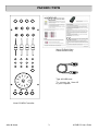
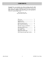
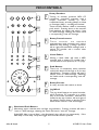
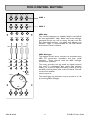
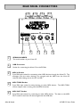
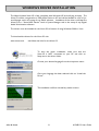
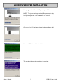
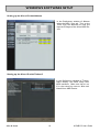
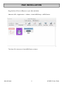
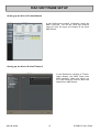
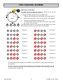
USER GUIDE
Publication AP7080
Allen & Heath
1
XONE:1D User Guide
Limited One Year Warranty
This product is warranted to be free from defects in materials or
workmanship for period of one year from the date of purchase by the
original owner.
To ensure a high level of performance and reliability for which this
equipment has been designed and manufactured, read this User Guide
before operating. In the event of a failure, notify and return the
defective unit to ALLEN & HEATH Limited or its authorised agent as
soon as possible for repair under warranty subject to the following
conditions
Conditions Of Warranty
The equipment has been installed and operated in accordance with the
instructions in this User Guide.
The equipment has not been subject to misuse either intended or
accidental, neglect, or alteration other than as described in the User
Guide or Service Manual, or approved by ALLEN & HEATH.
Any necessary adjustment, alteration or repair has been carried out by
ALLEN & HEATH or its authorised agent.
This warranty does not cover fader wear and tear.
The defective unit is to be returned carriage prepaid to ALLEN &
HEATH or its authorised agent with proof of purchase.
Units returned should be packed to avoid transit damage.
In certain territories the terms may vary. Check with your ALLEN &
HEATH agent for any additional warranty which may apply.
This product complies with the European Electro magnetic
Compatibility directives 89/336/EEC & 92/31/EEC and the
European Low Voltage Directives 73/23/EEC & 93/68/EEC.
This product has been tested to EN55103 Parts 1 & 2 1996 for use in
Environments E1, E2, E3, and E4 to demonstrate compliance with the
protection requirements in the European EMC directive 89/336/EEC.
During some tests the specified performance figures of the product were
affected. This is considered permissible and the product has been passed as
acceptable for its intended use. Allen & Heath has a strict policy of
ensuring all products are tested to the latest safety and EMC standards.
Customers requiring more information about EMC and safety issues can
contact Allen & Heath.
XONE:1D User Guide AP7080 Issue 3
Copyright © 2007 Allen & Heath Limited. All rights reserved
Allen & Heath Limited
Kernick Industrial Estate, Penryn, Cornwall, TR10 9LU, UK
http://www.allen-heath.com http://www.xone.co.uk
Allen & Heath
2
XONE:1D User Guide
PACKED ITEMS
Xone:1D Quick-Start
Guide and Warranty.
Type A-B USB Lead
To connect the Xone:1D
to your computer.
Xone:1D MIDI Controller
Allen & Heath
3
XONE:1D User Guide
CONTENTS
Congratulations on purchasing the Allen & Heath Xone:1D MIDI
Controller. To ensure that you get the maximum benefit from the unit
please spare a few minutes familiarizing yourself with the controls and
setup procedures outlined in this user guide. For further information
please refer to the additional information available on our web site, or
contact our technical support team.
http://www.xone.co.uk
http://www.allen-heath.com
Warranty...............................................
Packed Items ........................................
MIDI Controls .....................................
MIDI Control Section ........................
Rear Panel Connectors .....................
Windows Driver Installation............
Windows DAW Setup.......................
Mac Installation....................................
Mac DAW Setup .................................
MIDI Channel Number ....................
MIDI Map and Light Pipe Set Up ....
Allen & Heath
4
2
3
5
6
7
8
10
11
12
13
14
XONE:1D User Guide
MIDI CONTROLS
1
Rotary Encoders
Turning an encoder produces MIDI CC
(continuous controller) messages with a
unique controller number in two’s
compliment binary encoding (Map2) or Note
on messages (Map1) - see diagram overleaf.
These encoders feature a built in momentary
push switch. Pressing down on the encoder
knob activates the switch and sends a “note
on” MIDI message, releasing the switch sends
a corresponding “note off” message.
1
2
Rotary Potentiometers
These
controls
are
standard
potentiometers with end stops and a centre
detent for easy setting. Turning a pot from
left to right will send MIDI messages with a
unique CC number and a control value
from 0 to 127.
2
3
4
5
Linear Faders
Moving a linear fader will send a MIDI
message with a unique CC number and a
control value from 0 (bottom) to 127 (top).
3
Push Buttons
There are 12 momentary action switches
coded with letters M through to X for easy
identification. Pressing a switch will send a
unique “note on” MIDI message. Releasing
the switch sends a corresponding “note off”
message.
4
6
Rotary Encoder
A rotary encoder with switch, as above.
5
7
7
Jog Wheel
The jog wheel features an optical encoder,
which produces CC messages in a similar
way to the other encoders. Switches are
located at the top, bottom, left and right of
the wheel. Pushing down on the face of the
wheel sends note on / note off messages.
6
Illuminated Push Buttons
Momentary action switches with red light ring indicators. Pressing a switch will send a
“note on” MIDI message, releasing the switch will send a “note off” message.
If the MIDI Map is set to Map 1, the illuminated rings will stay on permanently. If the
MIDI Map is set to Map 2 they will toggle each time the switch is pressed.
Allen & Heath
5
XONE:1D User Guide
MIDI CONTROL SECTION
F5 F#5
B6 C6
A5 A#5
G5 G#5
MAP 1
E0
D-1
E-1
D0
CC32
CC33
CC34
CC35
MAP 2
E0
D-1
E-1
D0
CC9
CC11
CC13
CC15
CC8
CC19
CC10
CC18
F0
CC17
D#-1
N
A-1
M
C1
Q
CC12
A#-1
U
CC16
F-1
D#0
O
F#-1
G#0
R
C#1
CC14
P
S
G-1
V
T
A0
X
W
C0
CC37
CC36
A#-2
B-2
MIDI Map
Two control mappings are available, Map2 is the default
for most applications. Map1 differs only in the messages
generated by the top row of rotary encoders and the
four illuminated switches. Use Map2 with Ableton Live
software. Map1 is recommended for use with Native
Instruments Traktor software.
MIDI Messages
The diagram shows which controls are associated with
MIDI CC (continuous controller) and note on/off
messages. These controls send the MIDI messages
shown when operated.
The rotary encoders and jog wheel are digital controls
that send 2’s complement data rather than absolute
values. For a more in depth description of how to set up
the MIDI controls please refer to the Technical Tutorials
on the Xone website:
www.xone.co.uk
The switch light ring indicators may be turned on or off
by incoming MIDI messages.
A-2
C#-1
D1
B-1
Allen & Heath
G#-1
A#0
6
XONE:1D User Guide
REAR PANEL CONNECTORS
MIDI
THRU
SERIAL No:
IN
OUT
USB
TO PC
1
2
3
4
5
1
SERIAL NUMBER
The serial number of your Xone:1D
2
USB Connector
Socket for connecting the Xone:1D to the PC/Mac
3
MIDI In Socket
5-pin DIN style socket for connecting other MIDI devices through the Xone:1D. The
messages from the other device(s) are merged with the MIDI from the Xone:1D
controls before being sent to the PC via USB.
4
MIDI THRU Socket
5-pin DIN style socket for daisy-chaining to other MIDI devices. The MIDI THRU
socket outputs what is coming into the MIDI IN socket.
5
MIDI OUT Socket
5-pin DIN style socket for connecting to other MIDI devices. The data on the MIDI
OUT socket is the Xone:1D data merged with the USB data.
Allen & Heath
7
XONE:1D User Guide
WINDOWS DRIVER INSTALLATION
The Allen & Heath Xone:1D is fully compliant with Windows XP and will plug and play. The
Xone:1D will be recognised as a USB Audio Device in XP and will be labelled as such in System Manager and in the setup of any DAW software. Installation of the drivers will label the
Xone:1D as a “Xone MIDI Device” both in System Manager and in the setup of any Digital
Audio Workstation software.
The drivers must be installed for the Xone:1D to function if using Windows 2000 or Vista.
To download the drivers for the Xone:1D visit:
www.xone.co.uk
and follow the links for the Xone:1D.
To start the driver installation, make sure that the
Xone:1D is NOT connected to your PC and click on
Setup.exe in the driver folder.
Choose your desired language from the drop down menu.
Once your language has been selected click on “Install the
Driver”.
The installation will first uninstall any earlier drivers.
Allen & Heath
8
XONE:1D User Guide
WINDOWS DRIVER INSTALLATION
Now plug the Xone:1D to a USB port on your PC.
NOTE: The drivers will map to the USB socket used in the
installation. To ensure that your Xone:1D works on all
USB ports repeat the driver installation for each port.
Once the Xone:1D has been plugged in the installation will
initialise it.
Next the USB drivers will be installed.
This window indicates the installation is complete.
Allen & Heath
9
XONE:1D User Guide
WINDOWS SOFTWARE SETUP
Setting up the Xone:1D with Ableton
In the Preferences window of Ableton
select the MIDI / Sync tab. Turn on the
Track, Sync and Remote for both the
Input and Output of the Xone MIDI Device.
Setting up the Xone:1D with Traktor3
In the Preferences window of Traktor
select Hotkey and MIDI Setup then
MIDI interfaces. Make sure there is an
X in the active box next to Allen and
Heath Xone MIDI Device.
Allen & Heath
10
XONE:1D User Guide
MAC INSTALLATION
Plug the Xone:1D into a USB port on your Mac and follow:
Macintosh HD -> Applications -> Utilities -> Audio MIDI Setup -> MIDI Devices
The Xone:1D is shown as a Xone MIDI Device as above.
Allen & Heath
11
XONE:1D User Guide
MAC SOFTWARE SETUP
Setting up the Xone:1D with Ableton
In the Preferences window of Ableton select the
MIDI / Sync tab. Turn on the Track, Sync and Remote for both the Input and Output of the Xone
MIDI Device.
Setting up the Xone:1D with Traktor3
In the Preferences window of Traktor
select Hotkey and MIDI Setup then
MIDI interfaces. Make sure there is an
X in the active box next to Allen and
Heath Xone MIDI Device.
Allen & Heath
12
XONE:1D User Guide
MIDI CHANNEL NUMBER
C0
CC36
A#-2
CC37
B-2
A-2
JOG SELECT
C#-1
D1
B-1
G#-1
A#0
MIDI Channel Number
The MIDI channel number will default to channel 16, but can be
changed to any channel between 1 and 16.
To change the MIDI channel number and MIDI map:
1.
Connect the USB cable to the PC/Mac but not the Xone:1D
2.
Hold down the switch on the encoder shown in the diagram
3.
Connect the USB cable to the Xone:1D
4.
The illuminated switches will flash three times—now release
the switch on the encoder
The illuminated switches on the Xone:1D will display the current
MIDI channel number in binary format as shown below.
Channel 1
Channel 9
Channel 2
Channel 10
Channel 3
Channel 11
Channel 4
Channel 12
Channel 5
Channel 13
Channel 6
Channel 14
Channel 7
Channel 15
Channel 8
Channel 16
To change the channel number that the MIDI is transmitted on, rotate the encoder above
the jog wheel.
Once the desired channel has been selected, press and then release the switch on the
encoder above the jog wheel, the illuminated switches will flash once indicating that the
channel number has been set.
Allen & Heath
13
XONE:1D User Guide
MIDI MAP AND LIGHT PIPE SETUP
Changing the MIDI Map
Once the MIDI channel number has been stored, the illuminated switch to the far right of
the unit will flash indicating that the MIDI map may now be selected.
Map 1 (Traktor default)
The first switch (far left) is used to select MIDI Map 1. In
this map the top row of encoders send ‘Note On’ messages upon rotation (see MIDI Control Section p25).
The third button (centre right) is used to determine the status of the light rings. If the
third light ring is illuminated, then during normal operation all four light rings will stay
illuminated at all times.
If the third light ring is not illuminated then each light ring will toggle on and off on receipt of a specific MIDI ‘Note On’ message. The ‘Note On’ message that the light ring
responds to is the same ‘Note On’ message that is sent by the corresponding switch.
Therefore, referencing the MIDI Control Section, the first (far left) light pipe will toggle on and off when it receives a ‘Note On’ message of D1.
Map 2 (Ableton default)
The second switch (centre left) is used to select MIDI Map
2. In this map the top row of encoders send ‘Control
Change’ messages upon rotation (see MIDI Control Section p25).
The third button (centre right) is used to determine the status of the light rings. If the
third light ring is illuminated, then during normal operation all four light rings will toggle
on and off when their respective switch is pressed.
If the third light ring is not illuminated then each light ring will toggle on and off on receipt of a specific MIDI ‘Note On’ message. The ‘Note On’ message that the light ring
responds to is the same ‘Note On’ message that is sent by the corresponding switch.
Therefore, referencing the MIDI Control Section, the second (middle left) light pipe
will toggle on and off when it receives a ‘Note On’ message of B-1.
When the desired MIDI map has been selected, press and release the switch on the
encoder above the jog wheel. The illuminated switches will flash three times indicating
that the MIDI map has been stored and that the unit is now in its normal operating mode.
Allen & Heath
14
XONE:1D User Guide