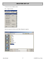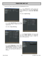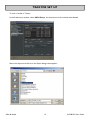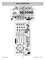
1
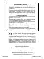
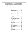
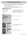
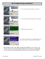
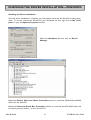
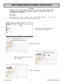
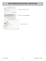
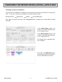
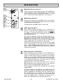
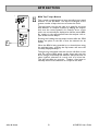
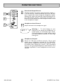
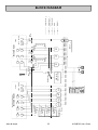
USER GUIDE
Publication AP6908
Allen & Heath
1
XONE:2D User Guide
Limited One Year Warranty
This product is warranted to be free from defects in materials or
workmanship for period of one year from the date of purchase by the
original owner.
To ensure a high level of performance and reliability for which this
equipment has been designed and manufactured, read this User Guide
before operating. In the event of a failure, notify and return the
defective unit to ALLEN & HEATH Limited or its authorised agent as
soon as possible for repair under warranty subject to the following
conditions
Conditions Of Warranty
The equipment has been installed and operated in accordance with the
instructions in this User Guide.
The equipment has not been subject to misuse either intended or
accidental, neglect, or alteration other than as described in the User
Guide or Service Manual, or approved by ALLEN & HEATH.
Any necessary adjustment, alteration or repair has been carried out by
ALLEN & HEATH or its authorised agent.
This warranty does not cover fader wear and tear.
The defective unit is to be returned carriage prepaid to ALLEN &
HEATH or its authorised agent with proof of purchase.
Units returned should be packed to avoid transit damage.
In certain territories the terms may vary. Check with your ALLEN &
HEATH agent for any additional warranty which may apply.
This product complies with the European Electro magnetic
Compatibility directives 89/336/EEC & 92/31/EEC and the
European Low Voltage Directives 73/23/EEC & 93/68/EEC.
This product has been tested to EN55103 Parts 1 & 2 1996 for use in
Environments E1, E2, E3, and E4 to demonstrate compliance with the
protection requirements in the European EMC directive 89/336/EEC.
During some tests the specified performance figures of the product were
affected. This is considered permissible and the product has been passed as
acceptable for its intended use. Allen & Heath has a strict policy of
ensuring all products are tested to the latest safety and EMC standards.
Customers requiring more information about EMC and safety issues can
contact Allen & Heath.
XONE:2D User Guide AP6908 Issue 2
Copyright © 2008 Allen & Heath Limited. All rights reserved
Allen & Heath Limited
Kernick Industrial Estate, Penryn, Cornwall, TR10 9LU, UK
http://www.allen-heath.com http://www.xone.co.uk
Allen & Heath
2
XONE:2D User Guide
CONTENTS
Congratulations on purchasing the Allen & Heath Xone:2D Professional
Digital Music Interface. To ensure that you get the maximum benefit from
the unit please spare a few minutes familiarising yourself with the controls
and setup procedures outlined in this user guide. For further information
please refer to the additional information available on our web site, or
contact our technical support team.
http://www.xone.co.uk
http://www.allen-heath.com
Warranty ..............................................
Software Installation PC....................
Packed Items........................................
Power Supply .......................................
Software Installation PC....................
Checking the Windows Driver
Installation ...........................................
Software Installation Apple Mac ......
Checking the Mac Driver
Installation ...........................................
MIDI Channel Setup...........................
MIDI Map and Light Pipe Setup .......
Using the Digital I/O ..........................
Soundcard Routing .............................
Ableton Setup......................................
Traktor Setup.......................................
Panel Drawings....................................
Introduction .........................................
Rear Connectors ................................
MIDI Controls .....................................
MIDI Control Section ........................
MIDI Shift Mode..................................
Input Chanel 5/6 .................................
BPM Section.........................................
Monitor Section ..................................
Block Diagram .....................................
Specifications........................................
Allen & Heath
3
2
3
4
5
6
8
9
11
12
13
14
15
16
18
20
21
22
25
27
28
29
30
32
33
34
XONE:2D User Guide
PACKED ITEMS
Check that you have received the following:
Xone:2D Professional Digital Music Interface
Check that the rear panel optical in/out blank plugs are fitted.
Safety Sheet
Important ! Read this sheet
before starting. Retain for
future reference.
Type A-B USB Lead
To connect the Xone:2D
to your computer.
Power Supply
Fit the correct mains adaptor for your region.
Allen & Heath
Registration Card
Complete and return
to Allen & Heath to
register your product.
4
XONE:2D User Guide
POWER SUPPLY
The Xone:2D contains its own Universal Voltage Input Power Supply unit with interchangeable heads for territory specific mains electricity outlets.
The power supply comes with a pin protector that needs to be removed before the desired head can be fitted.
To remove the pin protector, pull down on the release mechanism and pull the protector
out from the bottom.
To attach the required head, locate at the top first and then push down to locate and
lock in the release mechanism.
Allen & Heath
5
XONE:2D User Guide
SOFTWARE INSTALLATION PC
STOP!
BEFORE YOU DO ANYTHING WITH YOUR XONE:2D, PLEASE READ THE
FOLLOWING CAREFULLY TO ENSURE YOUR PC IS CORRECTLY SET UP TO
BE USED WITH THE DEVICE.
Software Installation (Windows 2000, XP and Vista)
Follow the procedure described below to install the USB audio and MIDI drivers:
1— Using the provided power supply, connect the
Xone:2D to your mains electricity supply.
Do not connect the 2D to the PC at this time.
2— Download the latest drivers
www.xone.co.uk/2D , and run DRIVERS setup.
from
3— Select your preferred language
4— Select “Install the driver”
5— When prompted, connect the 2D to
the PC with the USB lead.
The audio device will now initialise.
Allen & Heath
6
XONE:2D User Guide
SOFTWARE INSTALLATION PC
6— You will now be asked to unplug your Xone:2D
7— You will now be asked to plug in your Xone:2D again.
The USB drivers will now initialise.
8— The driver installation will complete without reboot
(XP, Vista) or ask you to reboot your PC (Win 2000).
Note: Always use the same USB port with your Xone:2D. When installing on a MS
Windows system, the drivers will be associated with the USB port that you are currently plugged
into. If you attempt to use the 2D with another USB port, or without installing the drivers at all,
the system may work but with degraded performance (XP, Vista), or may not work at all (2000).
Allen & Heath
7
XONE:2D User Guide
CHECKING THE DRIVER INSTALLATION—WINDOWS
Checking the Driver Installation
Once the driver installation is complete, you will need to check that the Xone:2D is being recognised. To do this, connect the Xone:2D to your PC/laptop and then right click on My Computer to open the System Properties window.
Select the Hardware tab then click on Device
Manager
Expand the Sound, Video and Game Controllers section to reveal the WDM audio and MIDI
drivers for the Xone:2D.
Expand the Universal Serial Bus Controllers section to reveal the Xone:2D ASIO driver and
its release (version) number —in this case V2.8.12.
Allen & Heath
8
XONE:2D User Guide
SOFTWARE INSTALLATION—APPLE MAC
STOP!
BEFORE YOU DO ANYTHING WITH YOUR XONE:2D, PLEASE READ THE
FOLLOWING CAREFULLY TO ENSURE YOUR PC IS CORRECTLY SET UP TO
BE USED WITH THE MIXER.
Mac OSX
Download the latest drivers from www.xone.co.uk/2D.
Xone_2D_Driver_x.x.x.dmg to reveal the window shown.
Open
the
Click on the Xone:2D mpkg file to
launch the driver installation.
Click on “Continue”.
Select install destination and then
click “Continue”.
Click on “Upgrade”.
Allen & Heath
9
XONE:2D User Guide
SOFTWARE INSTALLATION—APPLE MAC
Enter your system password.
Click on “Continue Installation”.
Restart your Mac.
Allen & Heath
10
XONE:2D User Guide
CHECKING THE DRIVER INSTALLATION—APPLE MAC
Checking the Driver Installation
Once the driver installation is complete, you will need to check that the Xone:2D is being recognised. To do this, connect the Xone:2D to your Mac and then select:
Mackintosh HD
Applications
Utilities
Audio MIDI Setup
Now select the Audio tab and in the “Properties For” dropdown box select Allen & Heath
Xone:2D.
In the Audio Input section, the
number of channels should be seen
as 8, running at 24 bit.
In the Audio Output section, the
number of channels should be seen
as 10, running at 24 bit.
The sample rate is selectable from
44.1 to 96kHz.
Now select the MIDI Devices tab
and make sure that the Xone:2D is
seen as a MIDI device as shown.
Allen & Heath
11
XONE:2D User Guide
MIDI CHANNEL SETUP
MIDI Channel Number
The MIDI channel number will default to
channel 16, but can be changed to any
channel between 1 and 16.
To change the MIDI channel number and
MIDI map:
1.
Hold down the switch on the
encoder shown in the diagram
2.
Connect the Power Supply to the
Xone:2D
3.
At the end of the start up sequence,
when the illuminated switches have
flashed three times, release the
switch on the encoder.
The illuminated switches on the Xone:2D
will display the current MIDI channel
G#2
CC45
CC44
F#1
G1
F1
A1
A#3
G2
E2
F#3
CC5
Channel 1
Channel 9
Channel 2
Channel 10
Channel 3
Channel 11
Channel 4
Channel 12
Channel 5
Channel 13
Channel 6
Channel 14
Channel 7
Channel 15
Channel 8
Channel 16
To change the channel number that the MIDI is transmitted on, rotate the encoder above
the jog wheel.
Once the desired channel has been selected, press and then release the switch on the
encoder above the jog wheel, the illuminated switches will flash once indicating that the
channel number has been set.
Allen & Heath
12
XONE:2D User Guide
MIDI MAP AND LIGHT PIPE SETUP
Changing the MIDI Map
Once the MIDI channel number has been stored, the illuminated switch to the far right of
the unit will flash indicating that the MIDI map may now be selected.
Map 1 (Traktor default)
The first switch (far left) is used to select MIDI Map 1. In
this map the top row of encoders send ‘Note On’ messages upon rotation (see MIDI Control Section p25).
The third button (centre right) is used to determine the status of the light rings. If the
third light ring is illuminated, then during normal operation all four light rings will stay
illuminated at all times.
If the third light ring is not illuminated then each light ring will toggle on and off on receipt of a specific MIDI ‘Note On’ message. The ‘Note On’ message that the light ring
responds to is the same ‘Note On’ message that is sent by the corresponding switch.
Therefore, referencing the MIDI Control Section, the first (far left) light pipe will toggle on and off when it receives a ‘Note On’ message of A#3.
Map 2 (Ableton default)
The second switch (centre left) is used to select MIDI Map
2. In this map the top row of encoders send ‘Control
Change’ messages upon rotation (see MIDI Control Section p25).
The third button (centre right) is used to determine the status of the light rings. If the
third light ring is illuminated, then during normal operation all four light rings will toggle
on and off when their respective switch is pressed.
If the third light ring is not illuminated then each light ring will toggle on and off on receipt of a specific MIDI ‘Note On’ message. The ‘Note On’ message that the light ring
responds to is the same ‘Note On’ message that is sent by the corresponding switch.
Therefore, referencing the MIDI Control Section, the second (middle left) light pipe
will toggle on and off when it receives a ‘Note On’ message of G2.
When the desired MIDI map has been selected, press and release the switch on the
encoder above the jog wheel. The illuminated switches will flash three times indicating
that the MIDI map has been stored and that the unit is now in its normal operating mode.
Allen & Heath
13
XONE:2D User Guide
USING THE DIGITAL I/O
SPDIF
IN
OPTICAL
OUT
IN
OUT
DIGITAL IN/OUT
Digital In
A digital input to the Xone:2D can be connected using either the COAX (RCA-type)
connection or the OPTICAL (TOSLINK) connection. The embedded software scans the
digital inputs and auto-senses which one is active.
When an external digital audio device is connected via the digital inputs, the system
sample rate will be locked to the sample rate of the digital audio source. This can crash
software applications if they are open when the digital input is connected.
To safeguard against this situation, connect your digital input in the following sequence:
1.
2.
3.
4.
Power down the Xone:2D
Connect the digital input device
Power up the Xone:2D
Open your music software application
Digital Out
The digital output of the Xone:2D can be connected to external equipment using either
the COAX (RCA-type) connection or the OPTICAL (TOSLINK) connection—the digital
signal is present on both.
The sample rate of the digital audio out is determined within the settings of your music
software application (Ableton, Traktor etc.), up to a maximum frequency of 96kHz.
When recording using an external digital recorder, match the system sampling rate to the
recording sample rate set on the external device.
Allen & Heath
14
XONE:2D User Guide
SOUNDCARD ROUTING
Architecture
The Xone:2D has a built-in 18-channel soundcard.
soundcard are of fixed architecture.
Soundcard Input
1-2 (Phono / Line)
3-4 (Phono / Line)
5-6 (Line / Mic)
7-8 (Digital in 1-2)
Soundcard Output
1-2 (RCA Phono)
3-4 (RCA Phono)
5-6 (RCA Phono)
7-8 (RCA Phono)
9-10 (Digital Out 3-4)
The inputs and outputs of the
Ableton Descriptor
1/2 (Stereo)
1 (Mono) & 2 (Mono)
3/4 (Stereo)
3 (Mono) & 4 (Mono)
5/6 (Stereo)
5 (Mono) & 6 (Mono)
7/8 (Stereo)
7 (Mono) & 8 (Mono)
Traktor Descriptor
Xone 2D Analogue In 1
Xone 2D Analogue In 2
Xone 2D Analogue In 3
Xone 2D Analogue In 4
Xone 2D Analogue In 5
Xone 2D Analogue In 6
Xone 2D Digital In 1
Xone 2D Digital In 2
Ableton Descriptor
1/2 (Stereo)
1 (Mono) & 2 (Mono)
3/4 (Stereo)
3 (Mono) & 4 (Mono)
5/6 (Stereo)
5 (Mono) & 6 (Mono)
7/8 (Stereo)
7 (Mono) & 8 (Mono)
9/10 (Stereo)
9 (Mono) & 10 (Mono)
Traktor Descriptor
Xone 2D Analogue Out 1
Xone 2D Analogue Out 2
Xone 2D Analogue Out 3
Xone 2D Analogue Out 4
Xone 2D Analogue Out 5
Xone 2D Analogue Out 6
Xone 2D Analogue Out 7
Xone 2D Analogue Out 8
Xone 2D Digital Out 3
Xone 2D Digital Out 4
Supported Buffer Sizes
The Xone:2D supports the following buffer sizes:
64, 96, 128, 192, 256, 384, 512, 768, 1024 etc.
NOTE:
To maintain the optimum functionality of your software please ensure that you
have the latest version installed. Also ensure that you are using the correct
configuration files for the software release.
Allen & Heath
15
XONE:2D User Guide
ABLETON SET UP
Launch your Ableton software and open the Preferences window.
1— In the ‘Preferences’ window select the ‘Audio’
tab. Once the 2D is connected, change the driver type
to ‘ASIO’ and set the Audio Device to ‘Xone:2D
USB ASIO driver’
In the ‘Settings’ section click on the ‘Input Config’
button.
2— Select the ‘Stereo’ options and de-select the
‘Mono’ options. You must click ‘OK’ for the changes
to take effect.
Now, in the ‘Settings’ section of the ‘Audio’ tab, click
on the ‘Output Config’ button.
3—Select the ‘Stereo’ options and de-select the
‘Mono’ options. You must click ‘OK’ for the changes
to take effect.
Now select the MIDI Sync tab of the Preferences
window.
4— Set the Track, Sync and Remote to ‘On’ for the
Xone:2D MIDI Input and Output.
Allen & Heath
16
XONE:2D User Guide
ABLETON SET UP
To load a live set in Ableton select:
File –> Open Live Set
Select the required .als file once the Open dialogue box appears:
Allen & Heath
17
XONE:2D User Guide
TRAKTOR SET UP
Launch your Traktor software and open the Preferences window.
1— In the ‘Preferences’ window expand the
‘Audio Setup’ section and select ‘Soundcard’.
Set the Audio Device to ‘Xone:2D USB ASIO
driver’
Now select ‘Input Routing’.
2— In the ‘Input Routing’ section, assign
the Xone:2D analogue or digital inputs to the
required deck.
Now select ‘Output Routing’.
3— In the ‘Output Routing’ section, first make
sure that the Mixer Mode is set to ‘External’.
Now assign the Xone:2D analogue or digital outputs to the required deck.
4— In the ‘Preferences’ window expand
the ‘Hotkey & MIDI Setup’ section, select
’MIDI Interfaces’, double click the ‘Active’
box next the Xone:2D MIDI and an ‘X’ will
appear. This will activate the MIDI from the
Xone:2D.
Allen & Heath
18
XONE:2D User Guide
TRAKTOR SET UP
To load a .tks file in Traktor:
In the Preferences window, select MIDI Setup. At the bottom of the window select Load.
Select the required .tks file once the Open dialogue box appears:
Allen & Heath
19
XONE:2D User Guide
PANEL DRAWINGS
SOUNDCARD INPUTS
3-4
L
L
SOUNDCARD OUTPUTS
1-2
L
7-8
L
5-6
L
3-4
L
1-2
L
R
R
R
R
R
R
R
5-6
DIGITAL AUDIO
SPDIF
PHONO
LINE
PHONO
LINE
IN
OPTICAL
OUT
IN
IN
MIDI
OUT
OUT
USB
SERIAL No:
DC 12V
1.25 A
24 BIT 96Khz
USB2
DIGITAL IN/OUT
TO PC
+
Allen & Heath
20
XONE:2D User Guide
INTRODUCTION TO THE XONE:2D
Welcome to the Allen & Heath Xone:2D Professional Digital Music Interface.
This system has been designed with the help of some of the world’s most cutting
edge DJs to provide a seamless integration of computer-based audio replay
systems. The Xone:2D comprises three main sections:
SOUNDCARD INPUTS
3-4
L
L
SOUNDCARD OUTPUTS
1-2
L
7-8
L
5-6
L
3-4
L
1-2
L
R
R
R
R
R
R
5-6
DIGITAL AUDIO
SPDIF
R
PHONO
LINE
PHONO
LINE
IN
OPTICAL
OUT
IN
IN
MIDI
OUT
24 BIT 96Khz
USB2
OUT
USB
SERIAL No:
DC 12V
1.0 A
BPM COUNTER— The BPM counter is
based on the award winning Allen & Heath
Xone:3D. The BPM Section features Auto BPM
Detection, Tap Tempo, sequencer remote
‘Start/Stop’ facility and a lever for ‘Pushing’ or
‘Pulling’ the generated MIDI Timing Clock.
TO PC
DIGITAL IN/OUT
MIDI CONTROLLER— The dedicated control strip provides a total of 87 MIDI messages
across two layers. The MIDI controls are a
combination of switches, rotary and fader controls, a multi-function jog wheel and a crossfader. The Xone:2D provides full control of
external MIDI devices including the most sophisticated DJ performance computer environments.
SOUNDCARD— The Xone:2D soundcard
has a total of 18 channels transmitted via
USB2.0. Eight input channels (6 analogue and 2
digital) and ten output channels (8 analogue and
2 digital) provide high quality 96kHz 24-bit audio transfer.
+
BPM Components
MIDI Components
Soundcard Components
Allen & Heath
21
XONE:2D User Guide
REAR CONNECTORS
1
SOUNDCARD INPUTS
3-4
L
2
L
7-8
L
5-6
L
3-4
L
1-2
L
R
R
R
R
R
R
R
5-6
3
SOUNDCARD OUTPUTS
1-2
L
DIGITAL AUDIO
SPDIF
PHONO
LINE
PHONO
LINE
IN
IN
OPTICAL
OUT
IN
MIDI
OUT
OUT
USB
SERIAL No:
4
DC 12V
1.0 A
24 BIT 96Khz
USB2
DIGITAL IN/OUT
TO PC
5
1
SOUNDCARD INPUTS 1-2, 3-4
RCA Phono sockets for connection to Soundcard Input Channels 1-2 and 3-4.
2
SOUNDCARD INPUT 5-6
RCA Phono sockets for connection to Soundcard Input Channels 5-6. The source for
Soundcard Input 5-6 may also be the microphone as selected on the front panel.
3
SOUNDCARD INPUTS PHONO / LINE SELECT
Switch for selecting between Phono and Line inputs for Soundcard Input Channels 1-2
and 3-4. Select ‘Line’ for line level inputs such as CD Players, or ‘Phono’ for turntables
that require RIAA equalisation.
4
CHASSIS EARTH TERMINAL
A screw terminal is provided for connecting the earth straps from turntables. This
connection earths the metal parts of the turntable to reduce hum, buzz or similar audible
noise getting into the system.
5
DC INPUT SOCKET
Connect the supplied external power supply to this socket.
Allen & Heath
22
XONE:2D User Guide
REAR CONNECTORS
SOUNDCARD INPUTS
3-4
L
L
SOUNDCARD OUTPUTS
1-2
L
7-8
L
5-6
L
3-4
L
1-2
L
R
R
R
R
R
R
R
5-6
DIGITAL AUDIO
SPDIF
PHONO
LINE
PHONO
LINE
IN
IN
OPTICAL
6
OUT
IN
MIDI
OUT
DIGITAL IN/OUT
24 BIT 96Khz
USB2
USB
SERIAL No:
DC 12V
1.0 A
OUT
TO PC
8
7
6
SPDIF DIGITAL INPUTS AND OUTPUTS
SPDIF is a popular digital audio interfacing standard for connecting two channel (stereo) audio
using a single COAX (RCA phono socket) or OPTICAL (TOSLINK socket) cable.
For reliable connection use a 75 ohm COAX cable intended for this function. Avoid the use of
cheap audio cables. Use purpose made optical fibre cables for connection using the Toslink
port. Make sure the blanking plugs provided are fitted to any unused Toslink sockets.
The SPDIF inputs and outputs are available only when your computer is connected via the USB
port. The computer provides the clocks needed for the soundcard to function.
Sample rates of 44.1, 48 and 96kHz are supported with the ability to interface with any digital
source up to 192kHz.
7
USB Connector
USB (Universal Serial Bus) V2.0 is an external peripheral interface standard for data
transmission. Xone:2D USB works at 480Mbps and provides up to 18 uncompressed
audio channels.
The USB connection is used to send/receive audio and MIDI data between the Xone:2D
and the connected computer. Use a standard USB type A to B lead to connect to your
computer. This is supplied with the Xone:2D.
8
MIDI IN / OUT
Connect to either a MIDI interface or directly to MIDI compatible equipment using a
standard 5 pin DIN (MIDI) lead. The MIDI output socket data duplicates what is sent via
the USB connection to the PC.
Incoming MIDI is merged with the Xone:2D MIDI and transported, via USB, to the PC or
Mac. Incoming MIDI data can also be used to remotely control the status of LED light
rings (with the exception of the Tap Tempo and Stop/Start.)
You can connect the MIDI OUT of one Xone:2D to the MIDI IN of another.
Allen & Heath
23
XONE:2D User Guide
REAR CONNECTORS
SOUNDCARD INPUTS
3-4
L
L
7-8
L
5-6
L
3-4
L
1-2
L
R
R
R
R
R
R
R
5-6
DIGITAL AUDIO
SPDIF
PHONO
LINE
PHONO
LINE
IN
IN
OPTICAL
OUT
IN
MIDI
OUT
DIGITAL IN/OUT
OUT
24 BIT 96Khz
USB2
USB
SERIAL No:
DC 12V
1.0 A
9
9
SOUNDCARD OUTPUTS
1-2
L
TO PC
SOUNDCARD OUTPUTS
RCA Phono sockets are provided for interfacing with the analogue audio outputs of the
Xone:2D soundcard. The soundcard outputs are grouped in pairs:- 1/2, 3/4 etc.
Allen & Heath
24
XONE:2D User Guide
MIDI CONTROLS
1
1
2
3
2
+
4
3
4
Allen & Heath
25
Rotary Encoders
Turning an encoder produces
MIDI CC (continuous
controller) messages with a
unique controller number in
‘Two’s Complement’ binary
encoding. Refer to the MIDI
CONTROL SECTION
(p25) for the differences
between Map 1 and 2 for these
controls.
These encoders feature a
built in momentary push
switch. Pressing down on the
encoder knob activates the
switch and sends a ‘Note On’
MIDI message, releasing the
switch sends a corresponding
‘Note Off’ message.
Rotary Potentiometers
These controls are standard
potentiometers with end
stops and a centre detent for
easy setting. Turning a pot
from left to right will send
MIDI messages with a unique
CC number and a control
value from 0 to 127.
Linear Faders
Moving a linear fader will send
a MIDI message with a unique
CC number and a control
value from 0 (bottom) to 127
(top).
Push Buttons
There are 24 momentary
action switches coded with
letters A through to X for
easy identification. Pressing a
switch will send a unique
‘Note On’ MIDI message.
Releasing the switch sends a
corresponding ‘Note Off’
message.
XONE:2D User Guide
MIDI CONTROLS
5
6
Jog Wheel
The jog wheel features an
optical encoder, which
produces CC messages in a
similar way to the other
encoders.
Switches are
located at the top, bottom,
left and right of the wheel.
Pushing down on the face of
the wheel sends ‘Note On’ /
‘Note Off’ messages.
7
Illuminated Push Buttons
Momentary action switches
with red light ring indicators.
Control of these indicators
depends upon system setup.
Please refer to MIDI MAP
AND LIGHT PIPE
SETUP (p13).
8
Cross Fader
Moving the cross-fader will
send a MIDI message with a
unique CC number and a
control value from 0 (fully
left) to 127 (fully right).
+
5
6
Rotary Encoder
A rotary encoder with
switch, as previously described.
7
8
Allen & Heath
26
XONE:2D User Guide
MIDI CONTROL SECTION
C#6 D6
G6 G#6
F6 F#6
D#6 E6
MAP 1
C3
A#1
C2
A#2
CC40
CC41
CC42
CC43
MAP 2
C3
A#1
CC21
CC23
CC20
CC22
CC31
CC30
C#3
G#3
E
CC25
CC24
CC29
B1
A
C2
CC28
B2
+
E3
H
G
D#2
J
MIDI Messages
The diagram shows which controls are
associated with MIDI CC (continuous
controller), ‘Note On’ and ‘Note Off’
messages. These controls send the MIDI
messages shown when operated.
The rotary encoders and jog wheel are
digital controls that send ‘Two’s
Complement’ data rather than absolute
values. For a more in depth description of
how to set up the MIDI controls please
refer to the Technical Tutorials on the
Xone website:
www.xone.co.uk
The switch light ring indicators may be
turned on or off by incoming MIDI
messages.
D
D2
F#2
MIDI Map
Two control mappings are available, Map 2
is the default for most applications. Map 1
differs only in the messages generated by
the top row of rotary encoders and the
four illuminated switches. Use Map 2 with
Ableton Live
software.
Map 1 is
recommended for use with Native
Instruments Traktor software.
CC26
C
F
I
CC27
C#2
B
F2
A3
A#2
F3
L
K
G#2
CC45
CC44
F#1
G1
F1
A1
A#3
G2
Allen & Heath
E2
F#3
CC5
27
XONE:2D User Guide
MIDI SHIFT MODE
F5 F#5
B6 C6
A5 A#5
G5 G#5
MAP 1
E0
D-1
E-1
D0
CC32
CC33
CC34
CC35
MAP 2
E0
D-1
CC9
CC11
CC8
CC10
CC19
CC18
F0
CC13
CC12
CC17
D#-1
A
E-1
F-1
B
C1
A-1
E
CC14
CC16
NOTE:
For logical operation, the cross-fader will
sent the Control Change message CC5
regardless of which layer is selected.
+
D
G#0
H
G
G-1
J
Shift Mode
To enter MIDI Shift Mode, press and hold
(for approximately 0.5 seconds) the
encoder above the jog-wheel until the BPM
display shows ’SFT’. The Xone:2D is in
Shift Mode whilst ’SFT’ is displayed and
sends the messages as shown.
The Xone:2D employs a fader ‘pick up’
algorithm so that controls do not jump
suddenly when used between the two
layers.
To exit Shift Mode press and hold the
encoder again.
D#0
F#-1
A#-1
I
CC15
C
F
C#1
D0
A0
L
K
C0
CC37
CC36
A#-2
B-2
A-2
C#-1
D1
B-1
Allen & Heath
G#-1
A#0
CC5
28
XONE:2D User Guide
INPUT CHANNEL 5/6
The input to Soundcard channel 5/6 can be either a Mic or Line source. The line source is
connected via RCA Phono connectors and the Mic source is via a female XLR3 socket.
Input channel 5/6 should be used for devices with a low output level such as MP3 players,
as the level control can be used to boost the signal level when the selector switch is in the
’LINE’ position. The level control adjusts the microphone input level when the selector
switch is in the ’MIC’ position.
Devices with output levels above –10dB should be connected to either Soundcard Input 12 or Soundcard Input 3-4.
1
1
MIC Input Socket
Female XLR3 connector for microphones
2
2
Level Control
The level control is used to amplify the incoming signal whether it
is a Mic or a Line source.
3
MIC / LINE Selector
Selects between Mic or Line input to Soundcard Input 5-6
3
Allen & Heath
29
XONE:2D User Guide
BPM SECTION
1
1
2
3
4
2
+
5
3
4
Allen & Heath
BPM Audio Source Selector
This five position switch allows the source to the BPM detection software to be changed between any of the three
stereo Soundcard inputs or Soundcard output 1-2. It also
has an ’OFF’ position if beat detection is not required.
BPM Display Window
Displays the analysed or tapped BPM. When the Xone:2D
is powered up, the display will indicate the version number
of the firmware within the unit.
The display will show SFT when in shift mode.
MIDI Start/Stop Reset
Sends MIDI start/stop messages to any connected sequencer. Note that these messages are sent on release of
the switch. Pressing and holding this switch will reset the
auto BPM detector, but won’t change the current status of
the Stop/Start control.
Pressing and holding this switch for approximately five seconds will turn off the Xone:2D internal MIDI clock and the
BPM display will change to OFF. Press and hold the STOP/
START button again until the three dashes are displayed to
reset the BPM and turn the MIDI clock back ON
The LED ring associated with this control will glow RED
when a Start message is sent, and will also turn ON/OFF
when a MIDI STOP/START/PAUSE command is received
from an external MIDI device connected to the MIDI IN
socket of the Xone:2D
MIDI Clock Push / Pull Switch
When attempting to get a sequencer, such as Ableton Live,
to play in time with another music source, for example a
CD or turntable which has been analysed by the auto beat
detector, it is not always possible to get it to start exactly
at the beginning of a bar. This control lets the DJ speed up
or slow down the MIDI clock, rather like pushing or pulling
a turntable platter when beat matching.
Pulling the lever to the left will slow the clock and the
BPM reading will drop, pushing the lever to the right will
speed up the clock and the BPM reading will rise.
When released, the MIDI clock will revert to the originally
displayed BPM.
You can manually set the BPM to any speed between 70
and 400 by pulling or pushing the lever; when the desired
speed is indicated on the display, press the TAP button to
lock the MIDI clock to this speed. To fine tune the BPM
to an exact figure, press and hold the TAP button and
when the decimal point is displayed, the speed can be
altered by 0.1BPM again by using the Push/Pull lever.
30
XONE:2D User Guide
BPM SECTION
5
+
5
Allen & Heath
BPM Tap Tempo Button
This control is used to tap in a beat manually at any speed
between 70 and 400 BPM. The taps are averaged, so the
greater number of taps the more accurate the result.
The tap button can also be used as a guide for the auto
beat detector on complex rhythms by helping the analyser
lock onto the correct pattern; for instance, drum ‘n bass
tracks can occasionally be displayed at half the actual BPM.
By tapping in the approximate beat the analyser will resync to the correct tempo.
Pressing and holding the tap tempo button shifts the BPM
display one place to the left so that the decimal can be
shown.
When the BPM is being speeded up or slowed down using
the push/pull lever, pressing the tap button will store the
currently displayed tempo.
The light ring associated with this control will flash in time
with the current BPM speed, usually along with the kick
drum, though occasionally the detector will synchronize to
other rhythmic elements of a track such as a hi-hat line.
This will not affect its accuracy. Tapping a few beats in
manually will force the detector to re-sync to the beat.
31
XONE:2D User Guide
MONITOR SECTION
1
1
2
3
2
Soundcard Output Selector
Latching switches are used to select Soundcard outputs 12, 3-4, 5-6 and 7-8. When all switches are in the ‘UP’ position, no signal will be sent through the headphone outputs.
Selecting any switch will route the relevant Soundcard output to the monitor section. If more than one switch is selected, all of the relevant Soundcard outputs will be routed
to the headphone outputs.
Headphones Level Control
Adjusts the level of the headphones signal.
82!
3
Allen & Heath
Warning ! To avoid damage to your
hearing do not operate the headphones or
sound system at excessively high volume.
Continued exposure to high volume sound
can cause frequency selective or wide range
hearing loss.
Headphones Outputs
Stereo 1/4” TRS jack and 3.5mm mini-jack. Plug in good
quality stereo headphones intended for DJ monitoring.
Use closed-ear headphones that provide maximum acoustic isolation when cueing your sources. We recommend
that you use high quality headphones rated between 30 to
100 ohms impedance. 8 ohm headphones are not recommended.
32
XONE:2D User Guide
Allen & Heath
6
8
33
Phones
Out 1-2
Out 3-4
Out 5-6
Out 7-8
5
7
DAC
2
4
DAC
1
3
DAC
Soundcard Outputs
DAC
COAX
OPTICAL
SPDIF
Out 1-2
BPM - MIDI
Clock Converter
BPM Audio
Mic/
Line
In 1-2
In 5-6
In 3-4
ADC
Level
R
I
A
A
ADC
R
I
A
A
AutoSense
OPTICAL
SPDIF
COAX
USB 2.0
ADC
2
4
6
Phono/
Line
1
3
5
Phono/
Line
Soundcard Inputs
MIDI Out
MIDI In
Digital Audio Out
Digital Audio In
Analogue Audio
BLOCK DIAGRAM
XONE:2D User Guide
SPECIFICATIONS
Frequency Response SC in to SC out
96kHz Sample Rate
10 Hz to 20kHz +0/-0.5dB
10 Hz to 36kHz +0/-3dB
THD + N Line In to Line Out +8 dBu
< 0.008%
Maximum Output Level
+9dBu
Maximum Input Level
+9dBu
Dynamic Range Output
104dB
System Dynamic Range Line In to Line Out
94dB
Mic Sensitivity
-50dBu to –30dBu
Input 5-6 Sensitivity
-3 to +22 dB
RIAA Input Sensitivity
7-48mV 1KHz/330pF
Dimensions and Weights
The console is fitted with rubber feet for desktop operation.
Width
Height
Depth
Weight
Desktop
160 mm (6.3”)
88 mm (3.5”) 358 mm (14”) 2kg (4.4 lbs)
Packed
304 mm (12”)
195 mm (7.7”) 475 mm (18.7”) 4.5kg (10 lbs)
375.60
Allen & Heath
87.80
108.00
160.00
358.00
34
XONE:2D User Guide