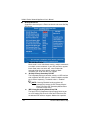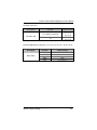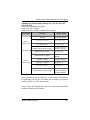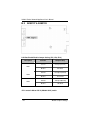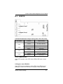
1
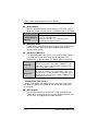
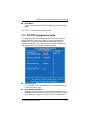
NA-821 Series SMB Network Appliance User’s Manual Disclaimers This manual has been carefully checked and believed to contain accurate information. AXIOMTEK Co., Ltd. assumes no responsibility for any infringements of patents or any third party’s rights, and any liability arising from such use. AXIOMTEK does not warrant or assume any legal liability or responsibility for the accuracy, completeness or usefulness of any information in this document. AXIOMTEK does not make any commitment to update the information in this manual. AXIOMTEK reserves the right to change or revise this document and/or product at any time without notice. No part of this document may be reproduced, stored in a retrieval system, or transmitted, in any form or by any means, electronic, mechanical, photocopying, recording, or otherwise, without the prior written permission of AXIOMTEK Co., Ltd. Copyright 2008 AXIOMTEK Co., Ltd. All Rights Reserved February 2009, Version A1.1 Printed in Taiwan ii Safety Approvals CE Marking FCC Class A FCC Compliance This equipment has been tested and complies with the limits for a Class A digital device, pursuant to Part 15 of the FCC Rules. These limits are designed to provide reasonable protection against harmful interference in a residential installation. If not installed and used in accordance with proper instructions, this equipment might generate or radiate radio frequency energy and cause harmful interference to radio communications. However, there is no guarantee that interference will not occur in a particular installation. If this equipment does cause harmful interference to radio or television reception, which can be determined by turning the equipment off and on, the user is encouraged to try to correct the interference by one or more of the following measurers: Reorient or relocate the receiving antenna. Increase the separation between the equipment and receiver. Connect the equipment into an outlet on a circuit different from that to which the receiver is connected. Consult the dealer or an experienced radio/TV technician for help. Shielded interface cables must be used in order to comply with emission limits. iii Safety Precautions Before getting started, read the following important cautions. 1. Be sure to ground yourself to prevent static charge when installing the internal components. Use a grounding wrist strap and place all electronic components in any static-shielded devices. Most electronic components are sensitive to static electrical charge. 2. Disconnect the power cords from the NA-821 Series before making any installation. Be sure both the system and the external devices are turned OFF. Sudden surge of power could ruin sensitive components. Make sure the NA-821 Series is properly grounded. 3. Do not open the system’s top cover. If opening the cover for maintenance is a must, only a trained technician is allowed to do so. Integrated circuits on computer boards are sensitive to static electricity. To avoid damaging chips from electrostatic discharge, observe the following precautions: Before handling a board or integrated circuit, touch an unpainted portion of the system unit chassis for a few seconds. This will help to discharge any static electricity on your body. When handling boards and components, wear a wristgrounding strap, available from most electronic component stores. Trademarks Acknowledgments AXIOMTEK is a trademark of AXIOMTEK Co., Ltd. IBM, PC/AT, PS/2, VGA are trademarks of International ® ® Business Machines Corporation. Intel and Pentium are registered trademarks of Intel Corporation. MS-DOS, Microsoft C and QuickBASIC are trademarks of Microsoft Corporation. Other brand names and trademarks are the properties and registered brands of their respective owners. iv Table of Contents Disclaimers......................................................................................................... ii Safety Approvals ............................................................................................... iii Safety Precautions............................................................................................ iv CHAPTER 1 INTRODUCTION ................................................................................... 1 1.1 General Description............................................................................... 1 1.2 Features ................................................................................................ 2 1.3 Specifications ........................................................................................ 2 1.3.1 System ........................................................................................... 2 1.3.2 Mechanical / Environmental........................................................... 4 1.4 Dimensions and Outlines....................................................................... 5 1.5 I/O Outlets............................................................................................. 6 1.5.1 Front Panel.................................................................................... 6 1.5.2 Rear Panel .................................................................................... 7 1.5.3 Internal & PCIe Module Configuration............................................ 8 1.5.4 Configuration I ............................................................................... 9 1.5.5 Configuration II .............................................................................. 9 1.5.6 Configuration III ........................................................................... 10 1.5.7 Configuration IV........................................................................... 10 CHAPTER 2 HARDWARE AND INSTALLATION .................................................... 11 2.1 Checklist ............................................................................................. 11 2.2 Board Layout ....................................................................................... 12 2.3 Jumper Settings .................................................................................. 13 2.3.1 CPLD Control Jumpers (JP3, JP4, JP5, JP6).............................. 14 2.3.2 CompactFlashTM Power Jumper (JP1)......................................... 14 2.3.3 WDT Jumper (JP7)..................................................................... 15 2.3.4 ME Clear CMOS Jumper (JP8)................................................... 15 2.3.5 Clear CMOS Jumper (JP9)........................................................... 16 2.3.6 Auto Power On Jumper (JP12)..................................................... 16 2.4 Connectors.......................................................................................... 17 2.4.1 Keyboard & PS/2 Mouse Connector (CN17)................................ 19 2.4.2 SATA Port 1 ~ 5 Connectors (CN11, CN15, CN8, CN10, CN7) ... 19 2.4.3 SYSTEM FAN1 ~ 2 Connectors (FAN1, FAN2) ........................... 20 2.4.4 CompactFlashTM Connector (CF1)............................................... 20 2.4.5 Front Panel Connector (CN18) .................................................... 21 2.4.6 LED Connectors (D2, D3)............................................................ 22 2.4.7 USB Port Connector (CN9) – USB 2x5 Box Header ..................... 22 2.4.8 Case Open Connector (JP11) – 2 Pin Header .............................. 23 2.5 Hardware Installation........................................................................... 23 2.5.1 Installing the CPU........................................................................ 23 2.5.2 Installing the Memory Module ...................................................... 27 CHAPTER 3 PHOENIX-AWARD BIOS UTILITY...................................................... 29 3.1 Entering Setup .................................................................................... 29 v 3.2 3.3 3.4 3.5 3.6 3.7 3.8 3.9 3.10 3.11 3.12 3.13 3.14 3.15 3.16 3.17 Control Keys........................................................................................ 30 Getting Help ........................................................................................ 30 The Main Menu ................................................................................... 31 Standard CMOS Setup Menu .............................................................. 32 Advanced BIOS Features.................................................................... 34 Advanced Chipset Features ................................................................ 38 Integrated Peripherals ......................................................................... 41 Power Management Setup .................................................................. 46 PnP/PCI Configuration Setup .............................................................. 49 PC Health Status................................................................................. 51 Frequency/Voltage Control ................................................................. 52 Load Fail-Safe Defaults ....................................................................... 53 Load Optimized Defaults ..................................................................... 54 Set Supervisor/User Password............................................................ 55 Save & Exit Setup ............................................................................... 56 Exit Without Saving ............................................................................. 57 APPENDIX A ENABLING LAN BYPASS FEATURE ............................................... 59 APPENDIX B MODULE JUMPER SETTINGS ........................................................ 61 B.1 AX90621 ........................................................................................... 61 B.2 AX93125 ........................................................................................... 64 B.3 AX93127 & AX93128 ........................................................................ 66 B.4 AX93129 ........................................................................................... 67 B.5 AX93131 ........................................................................................... 71 APPENDIX C AMT SETTINGS ................................................................................ 73 C.1 Entering MEBx .................................................................................. 73 C.2 Set & Change Password ................................................................... 74 vi ® C.3 Intel ME Settings............................................................................. 75 C.4 C.5 Intel AMT Settings .......................................................................... 78 AMT Web Console............................................................................ 82 ® NA-821 Series Network Appliance User’s Manual Chapter 1 Introduction This chapter contains general information and detailed specifications of the NA-821 Series Network Appliance Server. Chapter 1 contains the following sections: 1.1 General Description Features Specifications Dimensions I/O Outlets PCIe Module Configuration General Description The NA-821 is a 1U and rack mount network security hardware platform for VPN, firewall and other network security applications. It ® has extreme performance with Intel Core™ 2 Duo processor with FSB (Front Side Bus) up to 1333 MHz. Regarding LAN ports, it supports the I/O module design mindset. The NA-821 possesses abundant connections for RJ-45 and fiber ports in different I/O modules. The customers can easily do the installations with these modules by their truly requirement accordingly. As for the memory, it supports 4GB DDR2 667/800 in maximum. In addition to the stable and high performance hardware platform design, the NA-821 has the defaulted management capability as AMT (Active Management Technology) to be implemented (AMT function only for module AX93127, AX93128). The customers can perform the remote reset, remote boot and so on. Other features include LAN by-pass function controlled through WDT and GPIO pin definition for different LAN groups of I/O modules without any downtime, RAID function, and SATA II hard drives supported. The NA-821 doesn’t only provide high performance for processor, memory, storage interface and LAN ports connection, but also includes outstanding management capability. Introduction 1 NA-821 Series Network Appliance User’s Manual 1.2 Features ® Extreme performance Intel Core™2 Duo, Core™ 2 Quad processor, up to FSB 1333 MHz Supports Multiple PCIe I/O slots for LAN modules expansion ® Supports Intel AMT (Active Management Technology) for remote management (AMT function only for module AX93127, AX93128) Supports two S-ATA 2.5” HDD and RAID feature for event log or proxy data (Optional) Smart fan and intrusion control for case open (Optional) Suitable for network appliance; VPN, network bandwidth controller, firewall and UTM 1.3 Specifications 1.3.1 System System CPU ® TM Intel Core 2 Duo/Core™ 2 Quad processor with FSB 800/ 1066/ 1333 MHz System Chipset ® Intel Q35 + ICH9DO BIOS Award 32 Mbit PnP Flash BIOS (SPI) with function of BIOS redirected to COM port System Memory Up to 4GB for DDR2 667/800 S-ATA II Interface Two SATA II channels Network Interface The default is Ten 10/100/1000Mbps PCI Gigabit LAN ports and two LAN bypass segments More LAN ports expandability of the device by LAN modules Up to 11 LAN ports in total (maximum) 2 Introduction NA-821 Series Network Appliance User’s Manual SSD Supports CompactFlash™ Watchdog Timer 255 stepping for porting Expansion slot One PCI slot with 32-bit/ 33 MHz by AX90621 riser card One PCI-X slot for 64-bit/133MHz by AX90621 riser card (Optional) USB Two USB ports in the front, others are pin header internally Other Features Reset and power on/off function onboard (Pin) (optional) AMT (Active Management Technology) function support (AMT function only for module AX93127, AX93128) Supports SPI Flash Supports firmware upgrade functions by SMBus EEPOM (optional) LCD Module Yes. Programmable through RS-232 interface 4 hard keys on the front panel for users operation Power 270W ATX power supply Enclosure Smart fan control (To manage the fan Management speed and fan failure alert), intrusion control for case open (Optional) OS Compatibility Redhat Linux 2.4 and 2.6 Kernel Introduction 3 NA-821 Series Network Appliance User’s Manual 1.3.2 Mechanical / Environmental Form Factor 1U rack mount LED Power, HDD, Link/Act with transfer rate Operation Temp. 0°C ~ 40°C Storage Temp. -20°C ~ 70°C (14 ~ 158°F) Humidity 5% - 95% RH, non-condensing Chassis Material Steel Dimensions 44 mm (1.73”) (H) x 427.8 mm (16.83”) (W) x 430 mm (16.93”) (D) Certification FCC / CE pre-scan NOTE All specifications and images are subject to change without notice. 4 Introduction NA-821 Series Network Appliance User’s Manual 1.4 Dimensions and Outlines The following diagrams show you dimensions and outlines of the NA821 Series. Introduction 5 NA-821 Series Network Appliance User’s Manual 1.5 I/O Outlets Locate front and rear panel I/O outlets on the NA-821 Series server to connect serial and Ethernet interface devices. 1.5.1 6 Front Panel Console port It is a RJ RS-232 Console port for command line interface and diagnostic support by P.O.S.T (Power On Self Test). In AMT system did not support RS-232 console. (AMT function only for module AX93127, AX93128) USB Port Any special functions must be defined by solution provider. PCI Gigabit LAN It will be lighting when a twisted pair is connected to another Gigabit device on the port. PCIe LAN I/O module slot 2 It will be lighting when a twisted pair is connected to another Gigabit device on the port. PCIe LAN I/O module slot 1 It will be lighting when a twisted pair is connected to another Gigabit device on the port. Transfer Rate It shows network transfer rate while making a connection. Introduction NA-821 Series Network Appliance User’s Manual Activity It will be lighting when the server is transmitting or receiving a packet through the twisted pair ports. Transmitted LED (Dual color) for LAN port #1, port#2, port#3, port#4, port #5, port#6, port#7, port#8 port#9, port#10, port#11 (Optional) 1. The orange-color LED light indicates 10/100/1000Mbps transfer rate 2. The green-color LED light indicates 10/100Mbps transfer rate. 3. The LED will be dark when the Link/Active LED is lighting or flashing; it indicates 10Mbps transfer rate. 4. The LED will be dark when the Link/Active LED is dark, too. No networking devices are attached. 1.5.2 Rear Panel Introduction 7 NA-821 Series Network Appliance User’s Manual 1.5.3 8 Internal & PCIe Module Configuration Slot 1 AX93125 AX93126 Slot 2 AX93127 AX93128 Slot 3 AX93129 Introduction NA-821 Series Network Appliance User’s Manual 1.5.4 Configuration I PCIe x 1 Gigabit module with up to 4 LAN ports and PCIe x 1 Gigabit module with up to 2 LAN ports, two LAN bypass segments. AX93125 PCIe x1 Gigabit AX93127 4 2 ® ® Ethernet Controller Intel 82573 Intel 82573, 82566DM Interface Type RJ-45 RJ-45 Bypass Segment 2 N/A Slot Location Slot 1 Slot 2 PCI-X Slot (Optional) 1.5.5 Yes, PCI-X 64-bit/133 MHz Configuration II PCIe x4 Gigabit module with up to 2 SFP LAN ports and PCIe x1 Gigabit module with up to 2 LAN ports. PCIe x4 Gigabit PCIe x1 Gigabit AX93126 AX93127 2 0 0 2 ® ® Ethernet Controller Intel 82571 Intel 82573, 82566DM Interface Type SFP RJ-45 Bypass Segment N/A N/A Slot Location Slot 1 Slot 2 PCI-X Slot (Optional) Introduction Yes, PCI-X 64-bit/133 MHz 9 NA-821 Series Network Appliance User’s Manual 1.5.6 Configuration III PCIe x1 Gigabit module with up to 4 LAN ports and PCIe x1 Gigabit module with up to 3 LAN ports, two LAN bypass segments. AX93125 AX93128 4 0 PCIe x4 Gigabit PCIe x1 Gigabit 0 ® 3 ® Ethernet Controller Intel 82573 Intel 82573, 82566DM Interface Type RJ-45 RJ-45 Bypass Segment 2 N/A Slot Location Slot 1 Slot 2 PCI-X Slot (Optional) 1.5.7 N/A Configuration IV PCIe x4 Gigabit module with up to 2 SFP LAN ports and PCIe x1 Gigabit module with up to 3 LAN ports. AX93126 AX93128 PCIe x4 Gigabit 2 0 PCIe x1 Gigabit 0 ® 3 ® Ethernet Controller Intel 82571 Intel 82573, 82566DM Interface Type SFP RJ-45 Bypass Segment N/A N/A Slot Location Slot 1 Slot 2 PCI-X Slot (Optional) 10 N/A Introduction NA-821 Series Network Appliance User’s Manual Chapter 2 Hardware and Installation The NA-821 Series are convenient for your various hardware configurations. The chapter 2 will help you get familiar with the hardware. 2.1 Checklist The package bundled with your NA-821 Series should contain the following items: The NA-821 Series network appliance hardware platform Power cord x 1 Utility CD (including this User’s Manual) Mounting brackets for rack installation (left/right) x 2 Plastic stand for stack–up x 4 Mounting screws for disk drive and additional screws for this appliance’s spare parts Optional cable kits (1 x RJ console cable, 1 x PS/2 keyboard and mouse cable, 1 x VGA cable) If you can not find this package or any items are missing, please contact AXIOMTEK distributors immediately. If you order any optional components, the package might contain those additional hardware or documents accordingly. Hardware and Installation 11 NA-821 Series Network Appliance User’s Manual 2.2 12 Board Layout Hardware and Installation NA-821 Series Network Appliance User’s Manual 2.3 Jumper Settings This section provides the information about jumpers and connectors of NA-821 Series. Proper jumper settings configure the main board in this appliance to meet your application purpose. We are herewith listing a summary table of all jumpers and default settings for onboard devices, respectively. Jumper Default Setting Jumper Setting JP1 CF Power Short 1-2 for 3.3V (Default) Short 2-3 for 5V JP3 CPLD Control Short 1-2 For System reset Short 2-3 For Lan bypass Group 2(Default) JP4 CPLD Control Short 1-2 For System reset Short 2-3 For Lan bypass JP5 CPLD Control Short 1-2 For System reset Short 2-3 For Lan bypass Group 3(Default) JP6 CPLD Control Short 1-2 For System reset Short 2-3 For Lan bypass Group 4(Default) JP7 WDT Short 1-2 for SYS Reset Short 2-3 for Lan bypass (Default) JP8 Clear ME Short 1-2 for Normal (Default) Short 2-3 for Clear ME JP9 Clear CMOS Short 1-2 for Normal (Default) Short 2-3 for Clear BIOS CMOS JP12 Auto Power On Short for Auto Power On (Default) Open for Non-Auto Power On Hardware and Installation 13 NA-821 Series Network Appliance User’s Manual 2.3.1 CPLD Control Jumpers (JP3, JP4, JP5, JP6) CPLD control SYS RST or Lan Bypass interface. Description Function Jumper Setting JP3 ( 1-2 ) short JP4 ( 1-2 ) short JP5 ( 1-2 ) short JP6 ( 1-2 ) short CPLD WDT1 System reset CPLD WDT2 System reset CPLD WDT3 System reset CPLD WDT4 System reset JP3 ( 2-3 ) short JP4 ( 2-3 ) short JP5 ( 2-3 ) short JP6 ( 2-3 ) short CPLD WDT1 Lan bypass Group 2 CPLD WDT2 Lan bypass CPLD WDT3 Lan bypass Group 3 CPLD WDT4 Lan bypass Group 4 (Default) GROUP 2, GROUP 3, and GROUP 4 LAN Bypass or System reset can be controlled by GPLD. 2.3.2 TM CompactFlash Power Jumper (JP1) TM This jumper is to select the power for CompactFlash Description Function interface. Jumper Setting JP1 3.3V (Default) CF Power JP1 5V 14 Hardware and Installation NA-821 Series Network Appliance User’s Manual 2.3.3 WDT Jumper (JP7) You may need to use this jumper to set WDT output function for SYS Reset or LAN bypass. Description Function Jumper Setting JP7 WDT SYS Reset WDT WDT LAN Bypass (Default) 2.3.4 JP7 ME Clear CMOS Jumper (JP8) You may need to use this jumper to clear the ME CMOS memory if incorrect settings in the Setup Utility. Description Function Jumper Setting JP8 Normal (Default) ME Clear CMOS JP8 ME Clear CMOS Hardware and Installation 15 NA-821 Series Network Appliance User’s Manual 2.3.5 Clear CMOS Jumper (JP9) You may need to use this jumper is to clear the BIOS CMOS memory if incorrect settings in the Setup Utility. Description Function Jumper Setting JP9 Normal (Default) BIOS Clear CMOS JP9 BIOS Clear CMOS 2.3.6 Auto Power On Jumper (JP12) Do not remove this jumper. If you remove this jumper, NA-821 must use power button to be Power On. Description Function Jumper Setting JP12 Short for Auto Power On (Default) Auto Power On JP12 Open for Non-Auto Power On 16 Hardware and Installation NA-821 Series Network Appliance User’s Manual 2.4 Connectors Connectors connect the board with other parts of the system. Loose or improper connection might cause problems. Make sure all connectors are properly and firmly connected. Here is a summary table shows you all connectors on the main board. Connector Label Connector CompactFlash Connector Label TM Front Panel Connector CN18 COM2 Connector CN13 S-ATA Port 1 Connector CN11 LCM Connector CN14 S-ATA Port 2 Connector CN15 USB Port 3, 4 Connector CN9 S-ATA Port 3 Connector CN8 CRT Connector CN6 S-ATA Port 4 Connector CN10 Keyboard/Mouse Connector CN17 S-ATA Port 5 Connector CN7 ATX Power Connector CN5 SYSTEM FAN1 Connector FAN1 ATX12V CPU Power Connector CN2 SYSTEM FAN2 Connector FAN2 System BIOS U12 Internal Buzzer BU1 CN12 Internal Battery BAT1 Mini-PCI Connector LED Connector Hardware and Installation D2 LGA775 CPU Socket CF1 CPU1 17 NA-821 Series Network Appliance User’s Manual Connector Label Connector Label D3 240-Pin DDR2 Memory Channel-A DIMM1 Extension USB Port & Console Port CN20 240-Pin DDR2 Memory Channel-B DIMM2 Case Open JP11 LED Connector 18 Hardware and Installation NA-821 Series Network Appliance User’s Manual 2.4.1 Keyboard & PS/2 Mouse Connector (CN17) The board supports a keyboard and Mouse interface. Connector CN17 is a DIN connector for PS/2 keyboard Connection VIA “Y” Cable. Pin Signal Pin Signal 1 VCC 2 KBDATA 3 KBCLK 4 GND 5 VCC 6 VCC 7 MSDATA 8 MSCLK 9 GND 10 NC 2.4.2 CN17 SATA Port 1 ~ 5 Connectors (CN11, CN15, CN8, CN10, CN7) These SATA connectors are for high-speed SATA interface ports and they can be connected to serial ATA hard disk devices. Pin Signal Pin 1 GND 2 TX+ 3 TX- 4 GND 5 RX- 6 RX+ 7 Signal GND CN11, CN15, CN8, CN10, CN7 Hardware and Installation 19 NA-821 Series Network Appliance User’s Manual 2.4.3 SYSTEM FAN1 ~ 2 Connectors (FAN1, FAN2) You can connect the system cooling fan cable to FAN1/FAN2 for system cooling fan power. Pin Signal 1 Ground 2 +12V 3 Rotation Detection 2.4.4 TM CompactFlash FAN1, FAN2 Connector (CF1) TM The board is equipped with a CompactFlash disk type-II socket on TM the solder side to support an IDE interface CompactFlash disk card with DMA mode supported. The socket is especially designed to avoid TM incorrect installation of the CompactFlash disk card. When installing TM or removing the CompactFlash disk card, please make sure the system power is off. Pin Signal Pin 1 GND 2 Data 3 3 Data 4 4 Data 5 5 Data 6 6 Data 7 7 CS1# 8 GND 20 Signal 9 GND 10 GND 11 GND 12 GND 13 VCC 14 GND 15 GND 16 GND 17 GND 18 Address 2 19 Address 1 20 Address 0 21 Data 0 22 Data 1 23 Data 2 24 NC 25 GND 26 GND 27 Data 11 28 Data 12 29 Data 13 30 Data 14 31 Data 15 32 CS3# Hardware and Installation NA-821 Series Network Appliance User’s Manual Pin Signal Pin Signal 33 GND 34 IORD# 35 IOWR# 36 VCC 37 INTR 38 VCC 39 CSEL# 40 GND 41 RESET# 42 IORDY# 43 DMAREQ 44 DMAACK- 45 LED# 46 PATADET 47 Data 8 48 Data 9 49 Data 10 50 GND 2.4.5 Front Panel Connector (CN18) Power LED Pin 1, 3, 5 and 7 connect the system power LED indicator to its respective switch on the case. Pin 1 is +, and pin 5 is assigned as -. Pin 7 is defined as NC External Speaker and Internal Buzzer Connector Pin 2, 4, 6 and 8 connect to the case-mounted speaker unit or internal buzzer. Hardware Reset Pin 11 and 12 are designed for Hardware Reset. HDD Activity LED This connector extends to the hard drive activity LED on the control panel. This LED will flash when the HDD is being accessed. Pin 13 and 14 connect the hard disk drive and the front panel HDD LED. Power Button This 2-pin connector was designed at Pin 9 and 10. Hardware and Installation 21 NA-821 Series Network Appliance User’s Manual 2.4.6 LED Connectors (D2, D3) 3 1 4 2 D2 Connector Pin Signal 1-2 HDD LED (Pin 1 +, Pin 2 -) 3-4 Reserved D3 Connector Pin Signal 1-2 Power LED (Pin 1 +, Pin 2 -) 3-4 Reserved 2.4.7 USB Port Connector (CN9) – USB 2x5 Box Header The Universal Serial Bus (USB) port connector on the board is for the installation of peripherals supporting the USB interface. CN9 consists of two 4-pin standard USB ports. Pin Signal Pin Signal 1 USB POWER 2 USB POWER 3 USB P0- 4 USB P1- 5 USB P0+ 6 USB P1+ 7 USB GND 8 USB GND 9 NC 10 GND 22 CN9 Hardware and Installation NA-821 Series Network Appliance User’s Manual 2.4.8 Case Open Connector (JP11) – 2 Pin Header The case open connector on the board is for the case open detector. The function enable is by software AP. 2.5 Hardware Installation This section provides you the information how to install the NA-821 Series. 2.5.1 Installing the CPU 1. Get familiar with the LGA775 socket. Hook Lever Hardware and Installation Load Plate Contact 23 NA-821 Series Network Appliance User’s Manual 2. Hold and push down the hook of the lever, and pull the lever aside to unlock the cover. 3. Open the load plate, you can see the contact. Be careful not to touch the contact. 24 Hardware and Installation NA-821 Series Network Appliance User’s Manual 4. Place the CPU down into the socket. Be careful not to touch the contact. Hold the edges of the CPU, orientate it as the triangle indicator on the bottom-left corner the socket, and insert it into the socket. Triangle Indicator Hardware and Installation 25 NA-821 Series Network Appliance User’s Manual 5. Slightly push down and close the load plate. While pressing down lightly on load plate, engage the lever. Secure lever with load plate tab under retention tab of the lever. The CPU is completely locked. 26 Hardware and Installation NA-821 Series Network Appliance User’s Manual 2.5.2 Installing the Memory Module The main board supports two 240-pin DDR2 DIMM socket with maximum memory capacity up to 4GB None-ECC unbuffer memory. The following steps show you how to install the memory modules: 1. Push down each side of the DIMM socket. Align the memory module with the socket that notches of memory module must match the socket keys for a correct installation. Latch Hardware and Installation Latch 27 NA-821 Series Network Appliance User’s Manual 2. Insert the memory module into the socket and push it firmly down until it is fully seated. The socket latches are levered upwards and clipped on to the edges of the DIMM. 3. Install any remaining DIMM modules. 4. If the user use AMT function , must put the memory module into DIMM 1. (AMT function only for module AX93127, AX93128) Notice 1 When you are handling electrostatic discharge-sensitive (ESDs), please take precautions to avoid any damage from static electricity. Notice 2 The memory can support DDR2 667/800. 28 Hardware and Installation NA-821 Series Network Appliance User’s Manual Chapter 3 Phoenix-Award BIOS Utility The Phoenix-Award BIOS provides users with a built-in Setup program to modify basic system configuration. All configured parameters are stored in a battery-backed-up RAM (CMOS RAM) to save the Setup information whenever the power is turned off. 3.1 Entering Setup There are two ways to enter the Setup program. You may either turn ON the computer and press <Del> immediately, or press the <Del> and/or <Ctrl>, <Alt>, and <Esc> keys simultaneously when the following message appears at the bottom of the screen during POST (Power on Self Test). TO ENTER SETUP PRESS DEL KEY If the message disappears before you respond and you still want to enter Setup, please restart the system to try it again. Turning the system power OFF and ON, pressing the “RESET” button on the system case or simultaneously pressing <Ctrl>, <Alt>, and <Del> keys can restart the system. If you do not press keys at the right time and the system doesn’t boot, an error message will pop out to prompt you the following information: PRESS <F1> TO CONTINUE, <CTRL-ALT-ESC> OR <DEL> TO ENTER SETUP Phoenix-Award BIOS Utility 29 NA-821 Series Network Appliance User’s Manual 3.2 Control Keys Up arrow Move cursor to the previous item Down arrow Move cursor to the next item Left arrow Move cursor to the item on the left hand Right arrow Move to the item in the right hand Main Menu -- Quit and delete changes into CMOS Status Page Setup Menu and Option Page Setup Menu - Exit current page and return to Main Menu Increase the numeric value or make changes Esc key PgUp/“+” key PgDn/“− −“ key F1 key (Shift) F2 key F3 key Decrease the numeric value or make changes General help, only for Status Page Setup Menu and Option Page Setup Menu Change color from total 16 colors. F2 to select color forward, (Shift) F2 to select color backward Reserved F8 key Reserved Restore the previous CMOS value from CMOS, only for Option Page Setup Menu Load the default CMOS value from BIOS default table, only for Option Page Setup Menu Load the Setup default, only for Option Page Setup Menu Reserved F9 key Reserved F10 key Save all the CMOS changes, only for Main Menu F4 key F5 key F6 key F7 key 3.3 Getting Help Main Menu The online description of the highlighted setup function is displayed at the bottom of the screen. Status Page Setup Menu/Option Page Setup Menu Press <F1> to pop out a small Help window that provides the description of using appropriate keys and possible selections for highlighted items. Press <F1> or <Esc> to exit the Help Window. 30 Phoenix-Award BIOS Utility NA-821 Series Network Appliance User’s Manual 3.4 The Main Menu Once you enter the Award BIOS CMOS Setup Utility, the Main Menu appears on the screen. In the Main Menu, there are several Setup functions and a couple of Exit options for your selection. Use arrow keys to select the Setup Page you intend to configure then press <Enter> to accept or enter its sub-menu. NOTE If your computer can not boot after making and saving system changes with Setup, the Award BIOS will reset your system to the CMOS default settings via its built-in override feature. It is strongly recommended that you should avoid changing the chipset’s defaults. Both Award and your system manufacturer have carefully set up these defaults that provide the best performance and reliability. Phoenix-Award BIOS Utility 31 NA-821 Series Network Appliance User’s Manual 3.5 Standard CMOS Setup Menu The Standard CMOS Setup Menu displays basic information about your system. Use arrow keys to highlight each item, and use <PgUp> or <PgDn> key to select the value you want in each item. Date The date format is <day>, <date> <month> <year>. Press <F3> to show the calendar. day It is determined by the BIOS and read only, from Sunday to Saturday. date It can be keyed with the numerical/ function key, from 1 to 31. month year It is from January to December. It shows the current year of BIOS. Time This item shows current time of your system with the format <hour> <minute> <second>. The time is calculated based on the 24-hour military-time clock. For example, 1 p.m. is 13:00:00. 32 Phoenix-Award BIOS Utility NA-821 Series Network Appliance User’s Manual IDE Primary Master/Primary Slave These items identify the types of each IDE channel installed in the computer. There are 45 predefined types (Type 1 to Type 45) and 2 user’s definable types (Type User) for Enhanced IDE BIOS. Press <PgUp>/<+> or <PgDn>/<−> to select a numbered hard disk type, or directly type the number and press <Enter>. Please be noted your drive’s specifications must match the drive table. The hard disk will not work properly if you enter improper information. If your hard disk drive type does not match or is not listed, you can use Type User to manually define your own drive type. If selecting Type User, you will be asked to enter related information in the following items. Directly key in the information and press <Enter>. This information should be provided in the documentation from your hard disk vendor or the system manufacturer. If the HDD interface controller supports ESDI, select “Type 1”. If the HDD interface controller supports SCSI, select “None”. If the HDD interface controller supports CD-ROM, select “None”. CYLS. number of cylinders LANDZONE landing zone HEADS number of heads SECTORS number of sectors PRECOMP write precom MODE HDD access mode If there is no hard disk drive installed, select NONE and press <Enter>. Video Select the display adapter type for your system. Halt On This item determines whether the system will halt or not, if an error is detected while powering up. No errors The system booting will halt on any errors detected. (default) All errors Whenever BIOS detects a non-fatal error, the system will stop and you will be prompted. All, But Keyboard The system booting will not stop for a keyboard error; it will stop for other errors. All, But Diskette The system booting will not stop for a disk error; it will stop for other errors. All, But Disk/Key The system booting will not stop for a keyboard or disk error; it will stop for other errors. Phoenix-Award BIOS Utility 33 NA-821 Series Network Appliance User’s Manual Press <Esc> to return to the Main Menu page. 3.6 Advanced BIOS Features This section allows you to configure and improve your system, to set up some system features according to your preference. 34 Phoenix-Award BIOS Utility NA-821 Series Network Appliance User’s Manual CPU Feature Scroll to this item and press <Enter> to view the CPU Feature sub menu. Hard Disk Boot Priority Scroll to this item and press <Enter> to view the sub menu to decide the disk boot priority. Phoenix-Award BIOS Utility 35 NA-821 Series Network Appliance User’s Manual External Cache The external cache is the cache that sits between the processor and the system memory. Quick Power On Self Test This option speeds up Power on Self Test (POST) after you turn on the system power. If set as Enabled, BIOS will shorten or skip some check items during POST. The default setting is “Enabled”. Enabled Enable Quick POST Disabled Normal POST First/Second/Third Boot Device These items let you select the 1st, 2nd, and 3rd devices that the system will search for during its boot-up sequence. There is a wide range of options for your selection. Boot Other Device This item allows the user to enable/disable the boot device not listed on the First/Second/Third boot devices option above. The default setting is “Enabled”. Boot Up NumLock Status Set the the Num Lock status when the system is powered on. The default value is “On”. Security Option This item allows you to limit access to the system and Setup, or just to Setup. The default value is “Setup”. System If a wrong password is entered at the prompt, the system will not boot, the access to Setup will be denied, either. Setup If a wrong password is entered at the prompt, the system will boot, but the access to Setup will be denied. NOTE To disable the security, select PASSWORD SETTING at Main Menu and then you will be asked to enter a password. Do not type anything, just press <Enter> and it will disable the security. Once the security is disabled, the system will boot and you can enter Setup freely. APIC Mode Use this item to enable or disable APIC (Advanced Programmable Interrupt Controller) mode that provides symmetric multi- 36 Phoenix-Award BIOS Utility NA-821 Series Network Appliance User’s Manual processing (SMP) for systems. MPS Version Control For OS This item specifies the version of the Multiprocessor Specification (MPS). Version 1.4 has extended configuration tables to improve support for multiple PCI bus configurations and provide future expandability. Console Redirection This item allows you to enable or disable the BIOS boot up and redirect to console port feature. Available options are “Enable” and “Disable”. Baud Rate This item allows you to setup the data transfer rate for the console port. The default value is 9600. Available options are “9600”, “19200”, “38400”, “57600” and “115200”. Agent after boot This item allows you to enable or disable the agent after boot. Available options are “Enable” and “Disable”. ASF support The item provides the ability to enable or disable the ASF support (Alert Standard Format), which is an industry standard protocol used with Local Area Network (LAN) controllers. DMI Event Log Use this item to enable or disable the DMI Event Log function. Clear All DMI Event Log When this item is set to ‘Yes’, it enables users to clear all DMI Event Log. View DMI Event Log Press [Enter] to view the contents of the event log, and this setting allows you to enable or disable the event logging function. View DMI Events as Read Press [Enter] to mark all DMI Events as having been read. Event Log Capacity This item shows space availability for the event log. Phoenix-Award BIOS Utility 37 NA-821 Series Network Appliance User’s Manual Event Log Validity This item shows the information in the event log as valid or invalid. If the System Event Log is marked as invalid, clear the Event Log and reboot. Press <Esc> to return to the Main Menu page. 3.7 Advanced Chipset Features This section contains completely optimized chipset’s features on the board that you are strongly recommended to leave all items on this page at their default values unless you are very familiar with the technical specifications of your system hardware. 38 Phoenix-Award BIOS Utility NA-821 Series Network Appliance User’s Manual PCI Express Root Port Func Scroll to this item and press <Enter> to view the sub menu to decide the PCI Express Port. Press <Esc> to return to the Advanced Chipset Features page. VT-d Use this item to enable or disable the VT-d to support the remapping of I/O DMA transfers and device-generated interrupts. AMT BIOS Support You can enable this item to support AMT (active management technology) function to follow up the procedure for the access to AMI program screen. SOL Support You can enable this item to support SOL (Serial-Over-LAN) that can manage systems remotely. IDE-R Support Use this item to enable or disable the IDE-R (IDE Redirection) that allows an AMT enabled system to boot from an image, floppy, CD or DVD device which is located in the system running a management application. Phoenix-Award BIOS Utility 39 NA-821 Series Network Appliance User’s Manual *** VGA Setting *** PEG/Onchip VGA Control Use this item to choose the primary display card. On-Chip Frame Buffer Size Use this item to set the VGA frame buffer size. DVMT Mode DVMT (Dynamic Video Memory Technology) helps you select the video mode. DVMT/Fixed Memory Size DVMT (Dynamic Video Memory Technology) allows you to select a maximum size of dynamic amount usage of the video memory. The system would configure the video memory dependent on your application. Press <Esc> to return to the Main Menu page. 40 Phoenix-Award BIOS Utility NA-821 Series Network Appliance User’s Manual 3.8 Integrated Peripherals This section allows you to configure your SuperIO Device, IDE Function and Onboard Device. Phoenix-Award BIOS Utility 41 NA-821 Series Network Appliance User’s Manual OnChip IDE Device Scroll to this item and press <Enter> to view the sub menu OnChip IDE Device. 42 IDE HDD Block Mode Block mode is also called block transfer, multiple commands, or multiple sectors read/write. If your IDE hard drive supports block mode (most new drives do), select Enabled for automatic detection of the optimal number of block read/writes per sector the drive can support. On-Chip Primary/Secondary PCI IDE The integrated peripheral controller contains an IDE interface with support for two IDE channels. Select Enabled to activate each channel separately. The default value is “Enabled”. NOTE Choosing Disabled for these options will automatically remove the IDE Primary Master/ Slave PIO and/or IDE Secondary Master/Slave PIO items on the menu. IDE Primary/Secondary Master/Slave PIO The four IDE PIO (Programmed Input/Output) fields let you set a PIO mode (0-4) for each of the four IDE devices that the onboard IDE interface supports. Modes 0 to 4 provide Phoenix-Award BIOS Utility NA-821 Series Network Appliance User’s Manual successively increased performance. In Auto mode, the system automatically determines the best mode for each device. IDE Primary/Secondary Master/Slave UDMA Select the mode of operation for the IDE drive. Ultra DMA33/66/100/133 implementation is possible only if your IDE hard drive supports it and the operating environment includes a DMA driver. If your hard drive and system software both support Ultra DMA-33/66/100/133, select Auto to enable UDMA mode by BIOS. SATA Mode There are these options for you to set up SATA mode: IDE, RAID or AHCI. LEGACY Mode Support Legacy mode support allows devices to function in an operating environment that is not USB-aware. Press <Esc> to return to the Integrated Peripherals page. Phoenix-Award BIOS Utility 43 NA-821 Series Network Appliance User’s Manual Super IO Device Scroll to this item and press <Enter> to view the sub menu Super IO Device. Onboard Serial Port 1/2 Select an address and corresponding interrupt for the serial port. Options: 3F8/IRQ4, 2E8/IRQ3, 3E8/IRQ4, 2F8/IRQ3, Disabled, Auto. PWRON After PWR-Fail This item enables your computer to automatically restart or return to its operating status. Press <Esc> to return to the Integrated Peripherals page. 44 Phoenix-Award BIOS Utility NA-821 Series Network Appliance User’s Manual USB Device Setting Scroll to this item and press <Enter> to view the sub menu USB Device Setting. USB (CN16) is not working when USB2.0 Controller is disabled. Press <Esc> twice to return to the Main Menu page. Phoenix-Award BIOS Utility 45 NA-821 Series Network Appliance User’s Manual 3.9 Power Management Setup The Power Management Setup allows you to save energy of your system effectively. It will shut down the hard disk and turn OFF video display after a period of inactivity. ACPI Function This item allows you to enable/disable the Advanced Configuration and Power Management (ACPI). The function is always “Enabled”. ACPI Suspend Type This item specifies the power saving modes for ACPI function. If your operating system supports ACPI, such as Windows 98SE, Windows ME and Windows 2000, you can choose to enter the Standby mode in S1 (POS) or S3 (STR) fashion through the setting of this field. Options are: [S1 (POS)] The S1 sleep mode is a low power state. In this state, no system context is lost (CPU or chipset) and hardware maintains all system contexts. [S3 (STR)] The S3 sleep mode is a lower power state where the information of system configuration and open applications/files is 46 Phoenix-Award BIOS Utility NA-821 Series Network Appliance User’s Manual saved to main memory that remains powered while most other hardware components turn off to save energy. The information stored in memory will be used to restore the system when a “wake up” event occurs. Run VGABIOS if S3 Resume When this item is set Auto, the system will run VGA BIOS if it is resumed from the S3 state. Power Management This option allows you to select the type (or degree) of power saving for Doze, Standby, and Suspend modes. The table below describes each power management mode: Max Saving It is maximum power savings, only available for SL CPUs. The inactivity period is 1 minute in each mode. User Define It sets each mode. Select time-out periods in the PM Timers section. Min Saving It is minimum power savings. The inactivity period is 1 hour in each mode (except the hard drive). Disabled Default value Video Off Method This setting determines the manner in which the monitor is blanked. Turns OFF vertical and horizontal V/H SYNC+Blank synchronization ports and writes blanks to the video buffer DPMS Blank Screen Select this option if your monitor supports the Display Power Management Signaling (DPMS) standard of the Video Electronics Standards Association (VESA). Use the software supplied for your video subsystem to select video power management values. System only writes blanks to the video buffer. Video Off In Suspend This item defines if the video is powered down when the system is put into suspend mode. Suspend Type If this item is set to the default Stop Grant, the CPU will go into Idle Mode during power saving mode. Phoenix-Award BIOS Utility 47 NA-821 Series Network Appliance User’s Manual Suspend Mode After the selected period of system inactivity (1 minute to 1 hour), all devices except the CPU shut off. The default value is “Disabled”. Disabled System will never enter SUSPEND mode 1/2/4/6/8/10/20/30/4 0 Min/1 Hr Defines the continuous idle time before the system entering SUSPEND mode. If any item defined in (J) is enabled & active, SUSPEND timer will be reloaded HDD Power Down If HDD activity is not detected for the length of time specified in this field, the hard disk drive will be powered down while all other devices remain active. Soft-Off by PWR-BTTN This option only works with systems using an ATX power supply. It also allows the user to define which type of soft power OFF sequence the system will follow. The default value is “Instant-Off”. Instant-Off This option follows the conventional manner systems perform when power is turned OFF. Instant-Off is a soft power OFF sequence requiring only the switching of the power supply button to OFF Delay 4 Sec. Upon turning OFF system from the power switch, this option will delay the complete system power OFF sequence by approximately 4 seconds. Within this delay period, system will temporarily enter into Suspend Mode enabling you to restart the system at once. ** Reload Global Timer Events ** Global Timer (power management) events can prevent the system from entering a power saving mode or can awaken the system from such a mode. HPET Support Use this item to enable or disable HPET (High Precision Event Timer), which is designed to have very fine-grained resolution, fast access times, and support for a periodic behavior. 48 Phoenix-Award BIOS Utility NA-821 Series Network Appliance User’s Manual HPET Mode Use this item to configure the HPET (High Precision Event Timer) mode. Press <Esc> to return to the Main Menu page. 3.10 PnP/PCI Configuration Setup This section describes the configuration of PCI (Personal Computer Interconnect) bus system, which allows I/O devices to operate at speeds close to the CPU speed while communicating with other important components. This section covers very technical items that only experienced users could change default settings. Init Display First This item allows you to decide whether PCI Slot or AGP to be the first primary display card. Reset Configuration Data Normally, you leave this item Disabled. Select Enabled to reset Extended System Configuration Data (ESCD) when you exit Setup or if installing a new add-on cause the system reconfiguration a Phoenix-Award BIOS Utility 49 NA-821 Series Network Appliance User’s Manual serious conflict that the operating system can not boot. Options: Enabled, Disabled. Resources Controlled By The Award Plug and Play BIOS can automatically configure all boot and Plug and Play-compatible devices. If you select Auto, all interrupt request (IRQ), DMA assignment, and Used DMA fields disappear, as the BIOS automatically assigns them. The default value is “Manual”. IRQ Resources When resources are controlled manually, assign each system interrupt to one of the following types in accordance with the type of devices using the interrupt: 1. 2. Legacy ISA Devices compliant with the original PC AT bus specification, requiring a specific interrupt (such as IRQ4 for serial port 1). PCI/ISA PnP Devices compliant with the Plug and Play standard, whether designed for PCI or ISA bus architecture. The default value is “PCI/ISA PnP”. DMA Resources When resources are controlled manually, assign each system DMA channel as one of the following types, depending on the type of device using the interrupt: Legacy ISA Devices compliant with the original PC AT bus specification, requiring a specific DMA channel. PCI/ISA PnP Devices compliant with the Plug and Play standard, whether designed for PCI or ISA bus architecture. The default value is “PCI/ISA PnP”. PCI/VGA Palette Snoop Some non-standard VGA display cards may not show colors properly. This item allows you to set whether MPEG ISA/VESA VGA Cards can work with PCI/VGA or not. When enabled, a PCI/VGA can work with a MPEG ISA/VESA VGA card; when disabled, a PCI/VGA cannot work with a MPEG ISA/VESA Card. ** PCI Express relative items ** Maximum Payload Size When using DDR SDRAM and Buffer size selection, another consideration in designing a payload memory is the size of the buffer for data storage. Maximum Payload Size defines the maximum TLP (Transaction Layer Packet) data payload size for the device. 50 Phoenix-Award BIOS Utility NA-821 Series Network Appliance User’s Manual Press <Esc> to return to the Main Menu page. 3.11 PC Health Status This section supports hardware monitoring that lets you monitor those parameters for critical voltages, temperatures and fan speed of the board. Smart Fan1/2 Temperature The Smartfan provides two-way rotational speed. When the temperature reaches or exceeds the default value, two fans will run full speed. The default temperature: Smart fan1 : 45°C and Smart fan2 : 50°C. Current CPU Temperature These read-only fields show the functions of the hardware thermal sensor by CPU thermal diode that monitors the chip blocks to ensure a stable system. Current SYSTEM Temperature Show you the current system temperature. Vcore 12V/5V/3.3V Show you the voltage of 12V/5V/3.3V. Phoenix-Award BIOS Utility 51 NA-821 Series Network Appliance User’s Manual 3.12 Frequency/Voltage Control This section is to control the CPU frequency and Supply Voltage, DIMM OverVoltage and AGP voltage. CPU Clock Ratio Unlock Use this item to unlock CPU multiplier. CPU Clock Ratio Use this item to select the CPU’s frequency. Auto Detect PCI Clk The enabled item can automatically disable the clock source for a PCI slot without a module, to reduce EMI (ElectroMagnetic Interference). Spread Spectrum If spread spectrum is enabled, EMI (ElectroMagnetic Interference) generated by the system can be significantly reduced. CPU Host/PCI Clock Select Default or select a timing combination for the CPU and the PCI bus. When set to Default, the BIOS uses the actual CPU and PCI bus clock values. Press <Esc> to return to the Main Menu page. 52 Phoenix-Award BIOS Utility NA-821 Series Network Appliance User’s Manual 3.13 Load Fail-Safe Defaults When you press <Enter> on this item, a confirmation dialog box pops out to show you such a message: Please press “Y” to load default values that will be factory settings for accomplishing the optimal performance of system operations. Phoenix-Award BIOS Utility 53 NA-821 Series Network Appliance User’s Manual 3.14 Load Optimized Defaults This option allows you to load your system configuration with default values. These default settings are optimized to enable high performance features. To load CMOS SRAM with SETUP default values, please enter “Y”. If not, please enter “N”. 54 Phoenix-Award BIOS Utility NA-821 Series Network Appliance User’s Manual 3.15 Set Supervisor/User Password You can set a supervisor or user password, or both of them. The differences between them are: 1. 2. Supervisor password: You can enter and change the options on the setup menu. User password: You can just enter, but have no right to change the options on the setup menu. When you select this function, the following message will appear at the center of the screen to assist you in creating a password. ENTER PASSWORD Type a maximum eight-character password, and press <Enter>. This typed password will clear previously entered password from the CMOS memory. You will be asked to confirm this password. Type this password again and press <Enter>. You may also press <Esc> to abort this selection and not enter a password. To disable the password, just press <Enter> when you are prompted to enter a password. A message will confirm the password is getting disabled. Once the password is disabled, the system will boot and you can enter Setup freely. PASSWORD DISABLED When a password is enabled, you have to type it every time you enter the Setup. It prevents any unauthorized persons from changing your system configuration. Additionally, when a password is enabled, you can also require the BIOS to request a password every time the system reboots. This would prevent unauthorized use of your computer. You decide when the password is required for the BIOS Features Setup Menu and its Security option. If the Security option is set to “System”, the password is required during booting up and entry into the Setup; if it is set as “Setup”, a prompt will only appear before entering the Setup. Phoenix-Award BIOS Utility 55 NA-821 Series Network Appliance User’s Manual 3.16 Save & Exit Setup This section allows you to determine whether or not to accept your modifications. Type “Y” to quit the setup utility and save all changes into the CMOS memory. Type “N” to bring you back to the Setup utility. 56 Phoenix-Award BIOS Utility NA-821 Series Network Appliance User’s Manual 3.17 Exit Without Saving Select this option to exit the Setup utility without saving changes you have made in this session. Type “Y”, and it will quit the Setup utility without saving your modifications. Type “N” to return to the Setup utility. Phoenix-Award BIOS Utility 57 NA-821 Series Network Appliance User’s Manual MEMO 58 Phoenix-Award BIOS Utility NA-821 Series Network Appliance User’s Manual Appendix A Enabling LAN Bypass Feature What is the LAN by-pass meant for NA-821 Series? It doesn’t have any down time in network connections for two other network segments (LAN1 and LAN2) when any fetal errors occur to this device. The LAN by-pass feature covers three levels as below: 1. Power loss While the AC power loss occurs to this device, the LAN1 and LAN2 still can communicate with each other through hardware relay like as a short cut between two segments. If the power inlet can be normally done, the relay will turn to another correct position. 2. GPIO control It acts like a switch of the application software. You can enable the hardware relay feature through the GPIO control through the application programs. Then, the software solution provider can be more flexible to make it close with the program. 3. WDT (Watchdog Timer) The hardware supports the WDT (Watchdog Timer) function. While time-out happens after a defaulted period, the WDT will reset the system or make a short cut for two specific segments by hardware relay. The sample codes for the above features can be found in the CD, and they are only for customers’ reference as remarked. Enabling LAN Bypass Feature 59 NA-821 Series Network Appliance User’s Manual MEMO 60 Enabling LAN Bypass Feature NA-821 Series Network Appliance User’s Manual Appendix B Module Jumper Settings B.1 AX90621 Arbiter Enables/ Disables Description Arbiter Enables/ Disables Module Jumper Settings Function Jumper Setting Enables the Arbiter (Default) JP3 Open Disables the Arbiter JP3 Short 61 NA-821 Series Network Appliance User’s Manual PCI-X Singal Control(JP4 - JP8) 3V DUAL unlink (Default) Jumper Setting JP4 Open 3V DUAL link JP4 Short Arbiter GNT1 unlink (Default) JP5 Open Arbiter GNT1 link JP5 Short PX REQ-2 unlink (Default) JP6 Open PX REQ-2 link JP6 Short PX GNT-3 unlink (Default) JP7 Open PX GNT-3 link JP7 Short PX REQ-3 unlink (Default) JP8 Open PX REQ-3 link JP8 Short PX GNT-2 LINK JP10(1-2) PX AD20 LINK (Default) JP10(2-3) Description PCI-X signal control PC5 Link Select Function PCI-X Mode Select (Optional) JP9 1-2 Auto (Default) 3-4 PCI-X 50/66 JP2 JP1 N/A N/A OPEN SHORT OPEN 5-6 PCI 33/66 SHORT OPEN SHORT All Open PCI-X 100/133 OPEN SHORT Clock Frequency OPEN SHORT OPEN OPEN 50MHz 66MHz 25MHz 33MHz 50MHz 66MHz 100MHz 133MHz Remark: when JP9 select 1-2, do not connect JP1 & JP2 62 Module Jumper Settings NA-821 Series Network Appliance User’s Manual PCI-X Bus VIO Select Description Function Jumper Setting 3.3V DEFAULT (Default) JP11 (1-2), (4-5),(7-8) 5V JP11 (2-3), (5-6),(8-9) PCI-X Bus VIO PCI(CN2) IRQ Routing Setting(only select one on JP16, JP17, JP18 or JP19) Description IRQ Routing Module Jumper Settings Function Jumper Setting IRQH JP16 IRQG JP17 IRQF JP18 IRQE JP19 (Default) 63 NA-821 Series Network Appliance User’s Manual B.2 AX93125 LAN Port Enable/Disable Jumper Setting (JP3, JP4, JP11, JP12) Description LAN1 LAN2 LAN3 LAN4 Function Jumper Setting Normal JP3 Open(Default) Disable JP3 Short Normal JP12 Open(Default) Disable JP12 Short Normal JP4 Open(Default) Disable JP4 Short Normal JP11 Open(Default) Disable JP11 Short LAN bypass status LED (D6) Upper LED for lan1-2 port bypass status LED. Lower LED for lan3-4 port bypass status LED. LED active is LAN port in normal operation status. LED inactive is LAN port in LAN bypass status. 64 Module Jumper Settings NA-821 Series Network Appliance User’s Manual LAN Bypass Function Jumper Setting (JP1, JP2, JP5, JP6, JP7, JP8, JP9, JP10) LAN by pass divided into two groups: Group 1 for LAN 1 & LAN 2 Group 2 for LAN 3 & LAN 4 (support CPLD function) Description Function By WDT Group 1 LAN1 & LAN2 Jumper Setting JP10 Open (Default) Lan bypass Disable JP10 short (1-2) Lan always bypass JP10 short (2-3) GPIO Control Lan bypass Active JP8 Short, (Default) JP9 Open (Default) WDT Control Lan bypass JP1 short (1-2) CPLD Control Lan bypass JP1 short (2-3) (Default) By WDT or GPIO JP2 Open (Default) Group 2 LAN3 & LAN4 LAN bypass Disable JP2 short (1-2) LAN always bypass JP2 short (2-3) GPIO Control Lan bypass Active JP5 Short (Default) JP6 Open (Default) JP7 Open (Default) When you enter the system LAN bypass is active without setup the bios or application, and also you can control the LAN bypass to active or inactive by GPIO. Or CPLD (Group 2 only) Group 1 JP8 & JP9, Group2 JP5 & JP6 & JP7 are used the same GPIO control that come from CPU board. Module Jumper Settings 65 NA-821 Series Network Appliance User’s Manual B.3 AX93127 & AX93128 LAN Port Enable/Disable Jumper Setting (JP6, JP9, JP10) Description Function Jumper Setting Normal JP9 Open(Default) Disable JP9 Short Normal JP10 Open(Default) Disable JP10 Short Normal JP6 Open(Default) Disable JP6 Short LAN1 LAN2 LAN3 JP11 control LAN3 or PCI-X (AX90621 CN1) switch. 66 Module Jumper Settings NA-821 Series Network Appliance User’s Manual B.4 AX93129 LAN Port Enable/Disable Jumper Setting (JP24, JP25, JP31, JP33) Description LAN1 LAN2 LAN3 LAN4 Function Jumper Setting Normal JP31 Open (Default) Disable JP31 Short Normal JP24 Open (Default) Disable JP24 Short Normal JP25 Open (Default) Disable JP25 Short Normal JP33 Open (Default) Disable JP33 Short Power & HDD LED (D22) Upper LED for power status LED. Lower LED for HDD access status LED. LAN bypass status LED (D21) Upper LED for lan1-2 port bypass status LED. Lower LED for lan3-4 port bypass status LED. LED active is LAN port in normal operation Module Jumper Settings 67 NA-821 Series Network Appliance User’s Manual status. LED inactive is LAN port in LAN bypass status. LAN Bypass Function Jumper Setting (JP1, JP2, JP3, JP4, JP5, JP6, JP9, JP10, JP11, JP1) LAN by pass divided into two groups: Group 3 for LAN 1 & LAN 2 (support CPLD function) Group 4 for LAN 3 & LAN 4 (support CPLD function) Description Group 3 LAN1 & LAN2 Group 4 LAN3 & LAN4 Function Jumper Setting WDT Control Lan bypasss JP10 short (1-2) CPLD Control Lan bypasss JP10 short (2-3) (Default) By WDT or GPIO JP9 Open (Default) Lan bypass Disable JP9 short (1-2) Lan always bypass JP9 short (2-3) GPIO Control Lan bypasss Active JP1 Open(Default) JP2 short(Default) JP3 Open(Default) WDT Control Lan bypasss JP12 short (1-2) CPLD Control Lan bypasss JP12 short (2-3) (Default) By WDT or GPIO JP11 Open (Default) Lan bypass Disable JP11 short (1-2) Lan always bypass JP11 short (2-3) GPIO Control Lan bypasss Active JP6 short (Default) JP5 Open (Default) JP4 Open (Default) When you enter the system LAN bypass is active without setup the bios or application, and also you can control the Lan bypass to active or inactive by GPIO or CPLD. Group 3 JP1 & JP2 & JP3, Group 4 JP4 & JP5 & JP6 are used the same GPIO control that come from CPU board. 68 Module Jumper Settings NA-821 Series Network Appliance User’s Manual LAN PCI Routing Table Jumper Setting: LAN Port IRQ Routing Setting (JP14, JP15, JP19, JP20) Description Function LAN1 LAN2 LAN3 LAN4 Jumper Setting IRQ A (Default) JP14 short (1-2) IRQ D JP14 short (2-3) IRQ B (Default) JP20 short (1-2) IRQ C JP20 short (2-3) IRQ C (Default) JP19 short (1-2) IRQ B JP19 short (2-3) IRQ D (Default) JP15 short (1-2) IRQ A JP15 short (2-3) LAN Port ID Select Setting: LAN Port LAN 1 LAN 2 LAN 3 LAN 4 ID 20 JP27 short 2-3 (Default) X X JP28 short 1-2 ID 21 X JP21 short 2-3 (Default) JP16 short 1-2 X ID 22 X JP21 short 1-2 JP16 short 2-3 (Default) X ID 23 JP27 short 1-2 X X JP28 short 2-3 (Default) ID 24 JP26 short 2-3 X X JP30 short 1-2 ID 25 X JP22 short 2-3 JP17 short 1-2 X Module Jumper Settings 69 NA-821 Series Network Appliance User’s Manual LAN Port LAN 1 LAN 2 LAN 3 LAN 4 ID 26 X JP22 short 1-2 JP17 short 2-3 X ID 27 JP26 short 1-2 X X JP30 short 2-3 ID 28 JP29 short 2-3 X X JP32 short 1-2 ID 29 X JP23 short 2-3 JP17 short 1-2 X ID 30 X JP23 short 1-2 JP17 short 2-3 X ID 31 JP29 short 1-2 X X JP32 short 2-3 70 Module Jumper Settings NA-821 Series Network Appliance User’s Manual B.5 AX93131 Module Jumper Settings 71 NA-821 Series Network Appliance User’s Manual COM Port & USB Connector (CN2) connect SBC8A821 (CN20) Pin Signal Pin Signal 1 3 5 7 9 11 13 15 17 19 USB_D0P IO_GND USB_D1P IO_GND IO_GND NSOUT1 NDCD1NRI1NCTS1IO_GND 2 4 6 8 10 12 14 16 18 20 USB_D0N IO_GND USB_D1N USB_DUAL USB_DUAL NDSR1NRTS1NDTR1NSIN1 USB_OC0 COM Port & USB Connectors (CN1) 72 Pin RJ45 Signal Pin USB Signal 1 2 3 4 5 6 7 8 NDSR1NRTS1IO_GND NSOUT1 NSIN1 NDCD1NCTS1NDTR1- 1 2 3 4 5 6 7 8 USBF_VCC0 USBF_D0N USBF_D0P IO_GND USBF_VCC0 USBF_D1N USBF_D1P IO_GND Module Jumper Settings NA-821 Series Network Appliance User’s Manual Appendix C AMT Settings (AMT function only for module AX93127, AX93128) ® ® The Intel Active Management Technology (Intel AMT) has decreased a major barrier to IT efficiency that uses built-in platform capabilities and popular third-party management and security applications to allow IT a better discovering, healing, and protection their networked computing assets. ® In order to utilize Intel AMT you must enter the ME BIOS (CTRL + P during system startup), change the ME BIOS password, and then select ® “Intel AMT” as the manageability feature. C.1 Entering MEBx 1. You must go to BIOS TO start AMT function. 2. Exit from BIOS after starting AMT, and press Ctrl+P to enter MEBx Setting. It is better to press Ctrl+P before the screen popping out. AMT Settings 73 NA-821 Series Network Appliance User’s Manual C.2 Set & Change Password 1. You will be asked to set a password when first log in. The default password is ‘admin’. 2. You will be asked to change the password before setting ME. 3. You must confirm your new password while revising. (as Remark 1) Change Password Remark 1 The new password must contain: (example: !!11qqQQ) (default value) Eight characters One upper case One lower case One number One special symbol, such as ! 、 $ or ; , (、 、 " , excepted) Underline ( _ ) and space are valid characters for password, but they won’t make higher complexity. 74 AMT Settings NA-821 Series Network Appliance User’s Manual C.3 ® Intel ME Settings ® 1. Select Intel ME Configuration. 2. Select Intel ME State Control, and set it to ‘Enabled’. AMT Settings ® 75 NA-821 Series Network Appliance User’s Manual ® 3. Select Intel ME Firmware Local Update Qualifier, and set it to ‘Always Open’. ® 4. Select Intel ME Features Control, next Manageability Feature ® Selection, and set it to ‘Intel AMT’. 76 AMT Settings NA-821 Series Network Appliance User’s Manual ® 5. Select Intel ME Power Control, next ME On in Host Sleep States, and click the last option. 6. Exit from ME setting (the system will restart if first time setting). AMT Settings 77 NA-821 Series Network Appliance User’s Manual C.4 ® Intel AMT Settings ® 1. Select Intel AMT Configuration. 2. Key in the Host Name. If Intel AMT set to ‘DHCP‘, the Host name must be identical to the operating system mechanic. ® 78 AMT Settings NA-821 Series Network Appliance User’s Manual 3. Select TCP/IP to get into Network interface, and set it to ‘ENABLE’; into DHCP Mode, and set it to ‘ENABLE’ (as Remark 2) ; into Domain name, and set the Intel Management Engine domain name, such as ‘amt.intel.com’. Remark 2 AMT Settings DHCP Mode ‘DISABLED‘ : if DHCP Mode is disabled, you can make the following settings: 1. IP address 2. Subnet mask 3. Default Gateway address 4. Preferred DNS address 5. Alternate DNS address 6. Domain name 79 NA-821 Series Network Appliance User’s Manual 4. Select Provision Model to Change TO INTEL AMT 1.0 (Y/N), and set it to ‘N’; to Change TO Small Business (Y/N), and set it to ‘Y’. 5. Select SOL/IDE-R and set it to ‘Y’. Next, get into Username and Password to set it to ‘Enabled’; into Serial-Over-LAN to set it to ‘Enabled’; and into IDE Redirection to set it to ‘Enabled’. 6. Select Secure firmware update, and set it to ‘Enabled’. 80 AMT Settings NA-821 Series Network Appliance User’s Manual 7. Exit from MEBx after completing the AMT settings. AMT Settings 81 NA-821 Series Network Appliance User’s Manual C.5 AMT Web Console 1. From a web browser, please type http://(IP ADDRESS):16992, which connects to AMT Web. Example: http://10.1.40.135:16992 2. To log on, you will be required to type in username and password for access to the Web. USER: admin (default value) PASS: (MEBx password) 3. Enter the AMT Web. 82 AMT Settings NA-821 Series Network Appliance User’s Manual 4. Click Remote Control, and select commands on the right side. 5. When you have finished using the AMT Web console, close the Web browser. If you need more AMT information, please visit Intel Website accourdingly. AMT Settings 83 NA-821 Series Network Appliance User’s Manual MEMO 84 AMT Settings