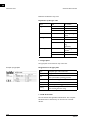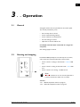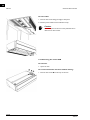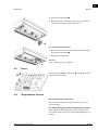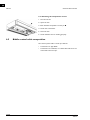
1
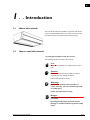
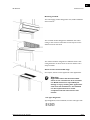
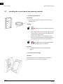
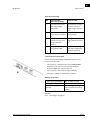
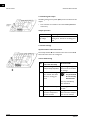
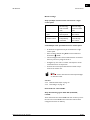
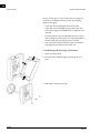
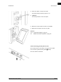
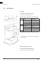
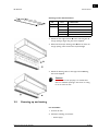
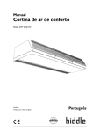
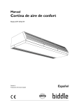
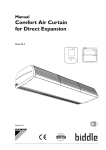
Manual
Comfort Air Curtain
Model DF
Version 2.0
Original Manual
a
English
en
COMFORT AIR CURTAIN
. . . Contents
1
Introduction
2
Installation
10
3
Operation
27
4
Maintenance
30
5
Faults
31
6
Service
36
en-2
1.1
1.2
1.3
1.4
1.5
2.1
2.2
2.3
2.4
2.5
2.6
2.7
2.8
2.9
3.1
3.2
3.3
3.4
4.1
4.2
5.1
5.2
5.3
6.1
6.2
6.3
6.4
6.5
About this manual
How to read this manual
About the unit
Restrictions on use
Safety instructions
Safety instructions
Delivery check
General working method
Suspending up the unit
Connecting the unit to the central heating system
Connecting the mains supply
Installing the control panel and external controls
Unit finishing
Powering up and testing
General
Starting and stopping
Adjusting the strength of the air curtain
Adjusting heating
Cleaning the unit
Scheduled maintenance
Safety instructions
Resolving simple problems
Troubleshooting
Safety instructions
Access
Fuses
Temperature cut-out
Biddle control cable composition
3
3
3
4
7
8
10
10
10
11
13
15
18
24
25
27
27
28
28
30
30
31
31
32
36
36
39
39
40
B
en
1 . . Introduction
1.1
About this manual
This manual describes the installation, operation and maintenance of the Model DF Comfort air curtain. The manual also
provides instructions and information about servicing.
1.2
How to read this manual
1.2.1 Marginal symbols used in the manual
The following symbols are used in this manual:
n
Note:
c
Caution:
Draws your attention to an important part of the
text.
If you do not perform this procedure or action
correctly, you may damage the device.
Follow the instructions strictly.
w
Warning:
If you do not perform this procedure or
action correctly, you may cause damage and/
or bodily injury.
Follow the instructions strictly.
d
Danger:
This indicates actions which are not
permitted.
Ignoring this warning may lead to serious
damage or accidents which may involve bodily
injury.
Manual version 2.0 (26-10-2012)
en-3
en
INTRODUCTION
COMFORT AIR CURTAIN
1.2.2 Pictograms used on the unit and in the manual
The following pictograms indicate potential risks or hazards.
The same pictograms will also be found on the unit.
Pictograms
PICTOGRAM
DESCRIPTION
w
You are entering an area of the unit containing live components.
Accessible to qualified maintenance staff only.
Exercise caution.
w
This surface or part can be hot. There is a risk of burns on contact.
1.2.3 Related documentation
Besides this manual, the following documents have been supplied with the unit:
•
1.3
Installation and servicing wiring diagram
About the unit
1.3.1 Application and operation of the air curtain
The air curtain is designed to separate indoor and outdoor climates. The unit draws air from the room and discharges it,
either heated or not, across the width of the doorway. The air
curtain removes the undesired effects of an open door by
either reducing the exchange of indoor and outside air, by
heating the entering air, or a combination of the two.
en-4
en
DF MANUAL
INTRODUCTION
Mounting methods
The free-hanging model is designed for free, visible installation
above the door.
The recessed model is designed for installation into a false
ceiling or into an alcove where the air inlet may be at some
distance from the unit itself.
The cassette model is designed for installation above a false
ceiling where the air inlet is close to the unit and the unit is
easily accessible.
Other versions and intended usage.
On request, versions can be supplied for other applications.
w
Warning:
Applications other than those described
above are not considered to be an intended
use. Biddle assumes no responsibility for
damage or injury resulting from applications
other than the intended use. The intended
use also implies observance of and
compliance with the instructions in this
manual.
1.3.2 Type designation
Type designations, when combined, form the unit’s type code:
DF S-100-W-F
DF M-150-E-C
DF L-200-A-R
Manual version 2.0 (26-10-2012)
en-5
en
INTRODUCTION
COMFORT AIR CURTAIN
Different combinations may arise.
Explanation of the type code
series
DF
air curtain
range
S
small
M
medium
L
large
unit size
100, 150, 200, 250
discharge length
(cm)
heating
W
hot water
E
electrical
A
zonder verwarming
(Ambient)
F
fee-hanging
model
C
cassette model
R
recessed model
mounting method
1.3.3 Type plate
The type plate can be found on top of the unit.
Example of a type plate
Designations on the type plate
Type
complete type code of the unit
M
weight of unit
Pmax
For water-heated models:
max. permissible operating pressure
U
connection voltage
Imax
max. current
Pmotor
max. fan power rating (per unit)
Pheating
For electrically heated models:
max. heating element rating
1.3.4 CE declaration
The unit satisfies the applicable CE standards. The complete
CE Declaration of Conformity can be found at: www.biddle.info.
en-6
en
DF MANUAL
INTRODUCTION
1.3.5 Modifications and changes
No changes or modifications may be made to the unit which
could influence its safety without the approval of Biddle. The
CE mark is no longer valid if the unit has been modified or
changed in any way.
1.3.6 Components and accessories
For all models:
•
control panel (supplied separately – can be used for multiple units)
•
control cable – Type RJ4 (supplied separately)
•
optional:
door contact switch (supplied separately)
For water-heated models (Type W):
•
valve for water-side control (supplied separately)
For recessed models (Type R):
1.4
•
telescopic discharge duct (supplied)
•
optional:
inlet grille for installation in alcove (supplied separately)
Restrictions on use
1.4.1 Operating environment
•
The unit may only be used indoors.
•
The unit may only be used in environments that are dry
and free from dust.
•
The device must not be used in environments with corrosive or chemically aggressive gases or vapours.
•
The unit is intended for use in ambient temperatures ranging from 0 °C to 40 °C.
These restrictions also apply to the control unit and/or control panel.
Manual version 2.0 (26-10-2012)
en-7
en
INTRODUCTION
COMFORT AIR CURTAIN
1.4.2 Requisite skills
•
You must be technically qualified to install, maintain or service this equipment in accordance with local legislation,
regulations and standards.
•
For operation in daily use, no special skills are required.
•
The unit is not intended for use by children or people with
an intellectual disability.
d
Danger:
NEVER attempt to perform installation,
maintenance, or servicing work on the unit
unless you are sufficiently qualified.
1.4.3 Application limitations with water heating
Application limitations for units with water heating
1.5
Heating medium
water with max. 20% glycol
Max. water supply
temperature
DF S-W, M-W: 90 °C
DF L-W: 70 °C
Max. air discharge
temperature
DF S-W, M-W: 70 °C
DF L-W: 45 °C
Max. operating pressure
8 bar
Safety instructions
1.5.1 Operation
en-8
w
Warning:
w
w
Warning:
Do not put any objects in the inlets and
outlets.
Do not obstruct the unit’s inlets or outlets.
Warning:
The upper surface of the unit becomes hot
during operation.
en
DF MANUAL
INTRODUCTION
c
Caution:
In exceptional situations, water may run out of the
unit. Therefore do not place anything under the unit
that could be damaged as a result.
1.5.2 Installation, maintenance and service
d
w
Danger:
The unit may be opened by qualified technical
staff only.
Warning:
Perform the following actions before opening
the unit:
1. Switch the unit off using the control panel.
2. Wait until the fans have stopped.
3. Allow the unit to cool down.
c
Caution:
The heat exchanger and/or the heating elements can
get very hot. Moreover, the fans may continue to
rotate for a while.
4. Disconnect the power supply (remove plug from power
point or move isolation switch to OFF).
5. For water-heated models:
connect the central heating supply (if possible).
w
Manual version 2.0 (26-10-2012)
Warning:
The fins of the heat exchanger are sharp.
en-9
en
2. .
2.1
Installation
Safety instructions
w
Warning:
w
Warning:
Installation work on the unit may only be
performed by qualified technical staff.
Before you begin: read the safety instructions.
See also:
1.5
"Safety instructions" on page 8
2.2
2.3
Delivery check
•
Check the unit and its packaging for correct delivery.
Immediately report to the driver and to the supplier any
damage caused in transit.
•
Make sure that all components and accompanying parts
have been supplied. Immediately report any defects to the
supplier.
General working method
2.3.1 Sequence of operations
Biddle recommends working as follows when installing the
Comfort Air Curtain:
1. Mount the unit.
2. For water-heated models:
connect the unit to the central heating system.
3. Connect the unit to the mains power supply.
4. Install the control panel and (any optional) connections to
external controls.
5. Complete appliance installation.
en-10
en
DF MANUAL
INSTALLATION
6. Turn the mains power supply on and check that the unit is
working properly.
General instructions
Some sections of this section only apply to certain models.
Where this is the case, it will be indicated. If no specific model
is referred to, the description applies to all models.
n
Note:
Make sure you perform all installation operations
that are required for your unit.
Check the type plate and consult the manual if in
doubt about the unit model and type.
n
Note:
Protect the unit from damage and ingress of dust,
cement, etc. throughout the installation. You can, for
instance, use the packaging for protection.
See also:
2.4
"Suspending up the unit" on page 11
2.5
"Connecting the unit to the central heating system" on
page 13
2.6
"Connecting the mains supply" on page 15
2.7
"Installing the control panel and external controls" on
page 18
2.8
"Unit finishing" on page 24
2.9
"Powering up and testing" on page 25
2.4
Suspending up the unit
2.4.1 Unit placement
•
Manual version 2.0 (26-10-2012)
Make sure that the structure from which the unit is about
to be suspended can bear the weight of the unit. The unit’s
weight is marked on its type plate.
en-11
en
INSTALLATION
COMFORT AIR CURTAIN
•
Note the following dimensions:
-
w
The unit must be at least as wide as the door opening
(dimension b).
Position the unit as near to the doorway as possible.
Position the unit as close to the top of the door as possible.
Warning:
The minimum installation height (dimension
h) is 1.8 m.
The top of the unit may get hot. The unit
should be placed with at least 25 mm ceiling
clearance (dimension x).
-
If the unit is mounted against the ceiling:
Make sure that air can enter the unit freely above the
unit.
See also:
1.3.3 "Type plate" on page 6
2.4.2 Suspending and securing the unit
1. Position the four M8 screw threads. Make sure the thread
rods are perpendicular.
Dimensions for free-hanging and recessed units.
en-12
SIZE
TYPE
DIMENSIONS
a
all DF F, R
as needed
b
all DF F, R
35 mm
c
all DF F, R
290 mm
d
DF 100-F, 100-R
896 mm
DF 150-F, 100-R
1396 mm
DF 200-F, 200-R
1896 mm
DF 250-F, 250-R
2396 mm
en
DF MANUAL
INSTALLATION
Dimensions of hole and suspension for cassette model
SIZE
TYPE
DIMENSIONS
a
DF 100-C
1012 mm
DF 150-C
1512 mm
DF 200-C
2012 mm
DF 250-C
2512 mm
b
all DF C
705 mm
c
DF 100-C
937 mm
DF 150-C
1437 mm
DF 200-C
1937 mm
DF 250-C
2437 mm
all DF C
641 mm
d
2. Screw a lock nut 1 onto each threaded rod.
3. Attach the unit to the threaded rods.
4. Secure the unit by tightening the lock nuts 1.
2.5
Connecting the unit to the central heating system
See also:
6.2.2 "Opening the unit" on page 37
Manual version 2.0 (26-10-2012)
en-13
en
INSTALLATION
COMFORT AIR CURTAIN
2.5.1 Particulars
c
Caution:
The central heating system’s supply and return pipes
must be attached to the correct connectors 1. The
directions are indicated on the unit using arrows.
•
Keep the connectors 1 in place by using pliers when connecting the pipes.
•
Biddle recommends inserting a valve and a bleed on both
pipes close to the unit.
Application limitations for units with water heating
Heating medium
water with max. 20% glycol
Max. water supply
temperature
DF S-W, M-W: 90 °C
DF L-W: 70 °C
Max. air discharge
temperature
DF S-W, M-W: 70 °C
DF L-W: 45 °C
Max. operating pressure
8 bar
2.5.2 Frost protection
Take the following precautions if you install the unit in a room
where frost may occur:
•
Provide for constant circulation of the water at the right
temperature;
•
Add up to 20% glycol to the water when the unit is not in
operation during the wintertime;
•
Or bleed the system and the unit.
2.5.3 Connecting the water-side control
1. Open the unit.
2. Connect the unit and the three-way valve to the central
heating system as shown in the diagram.
n
en-14
Note:
The diameter of the bypass pipe from Connection B
to the return pipe must be at least 22 mm.
en
DF MANUAL
INSTALLATION
3. Connect the valve to Terminal Block 1 as shown in the
electrical diagram.
4. Open the valve manually using the handle (Position ‘MAN’).
5. Fill and bleed the system.
6. Check the connections for leaks.
7. Return the handle to its starting position
(Position ‘AUTO’).
2.6
Connecting the mains supply
2.6.1 Particulars
For all models:
w
w
Warning:
The unit must be grounded.
Warning:
Connect the unit in accordance with the
applicable local requirements.
For water-heated models and models without heating:
Manual version 2.0 (26-10-2012)
•
The unit can be switched on and off from the power supply. This requires that the control panel be configured for
this purpose.
•
If the unit has been fitted with a power cable and
plug on delivery:
Ensure that an earthed wall socket is available no farther
than 1.5 m from the connections side of the unit.
en-15
en
INSTALLATION
COMFORT AIR CURTAIN
•
If the unit has not been fitted with a power cable and
plug:
Connect the unit to the mains using a power cable (not
supplied). Maximum ratings are specified on the type plate.
It must be possible to interrupt the power supply to the
unit. You may choose to use either a plugged power supply cable or an isolation switch.
Electrically-heated models:
Warning:
w
Do not turn on the unit from the power
supply. Use the control panel.
•
Connect the unit to the mains using a power cable (not
supplied). Maximum ratings are specified on the type plate.
•
An isolation switch (not supplied) must be fitted between
the unit and the power supply. This switch must:
-
be all-pole;
have a contact separation of at least 3 mm
be positioned no farther than 4 m from the connection
side of the unit
See also:
1.3.3 "Type plate" on page 6
2.6.2 Fuse ratings
w
Warning:
Each unit should be individually fused
according to the table below.
Fuse ratings
MAXIMUM CURRENT ON
MAXIMUM FUSE VALUE A
TYPE PLATE L1, L2 OR L3
en-16
<= 10 A
16 A
<= 15 A
20 A
<= 20 A
25 A
<= 25 A
35 A
<= 35 A
50 A
<= 50 A
63 A
<= 65 A
80 A
en
DF MANUAL
INSTALLATION
MAXIMUM CURRENT ON
TYPE PLATE L1, L2 OR L3
MAXIMUM FUSE VALUE A
<= 80 A
100 A
<= 102 A
125 A
n
Note:
Multiple units may only be served by a common fuse
is their total current consumption is less than 10A.
2.6.3 Connect the unit
For units supplied without a mains power cable/plug
only:
w
Warning:
Only connect the unit if you are qualified to
work on three-phase power systems.
Make sure that the mains power supply has
been turned off.
1. Fit the isolation switch and connect it to the power supply.
2. Open the unit.
3. Feed the power cable through the cable gland 1.
4. Connect the cable to the unit’s power terminal 2 as
shown in the wiring diagram.
5. Connect the power supply cable to the isolation switch.
c
Caution:
Do not yet switch the mains supply on.
See also:
6.2.2 "Opening the unit" on page 37
Manual version 2.0 (26-10-2012)
en-17
en
INSTALLATION
2.7
COMFORT AIR CURTAIN
Installing the control panel and external controls
2.7.1 Control panel details
Positioning
•
You may fix the control panel either to the wall or to a
standard socket.
Cabling
n
Note:
Take the following into account, otherwise faults may
occur:
- Keep control cables away from electromagnetic fields
and interference sources such as high-voltage cables
and fluorescent-light starters.
- Stretch control cables out or roll them up neatly.
- The control cable between the control panel and the
connected unit may not be any longer than 30 m.
n
Note:
Use Biddle control cables only (Type RJ4). Standard
modular telephone cable is not suitable.
See also:
2.7.6 "Multiple units operated from one control panel" on
page 21
2.7.2 Control panel settings
Optional
Several dip switches are located inside the control panel.
These allow the control panel to be configured.
en-18
en
DF MANUAL
INSTALLATION
Control panel settings
NO.
POSITION OFF
(FACTORY SETTING)
1
unit remains turned off
after supply voltage
interruption
unit continues running in
the same mode after
supply voltage interruption
2
fans continue running as
long as the unit is turned
on
fans do not run if heating
is not required
3
heating is turned off
once the set room temperature has been
reached
heating is always on as
long as the unit is turned
on
4
display heating settings
using multiple LEDs
display heating settings
with only one LED (does
not affect operation)
POSITION ON
2.7.3 External control input
A door switch and/or building management system can be
connected to the input.
•
The connector is located on the control PCB (INHIBIT
connector). This connector has been fed through to
Connector 1 on the outside of the unit.
•
This connector is fitted with a bridge on delivery.
•
The input is suitable for potential-free switches.
Working of the input
contact closed (or bridged)
unit operates normally
contact open
unit remains off
resistor across contact
(3.3 kΩ)
unit working, but heating
remains turned off (summer
mode)
See also:
2.7.5 "Unit settings" on page 20
Manual version 2.0 (26-10-2012)
en-19
en
INSTALLATION
COMFORT AIR CURTAIN
2.7.4 Fault signal output
A building management system (BMS) can be connected to the
output.
•
The connector is located on the control PCB (HEALTHY
connector).
Output operation
24 VDC
unit configured as a normal unit
no power supply voltage
temperature cut-out has turned the
heating off or the unit is not being powered
2.7.5 Unit settings
Optional unless otherwise stated
Several dip switches 1 are located on the unit’s control PCB.
These allow the unit to be configured.
Control PCB settings
NO.
POSITION OFF
(FACTORY SETTING)
1
fan and heating mode
independently adjustable
2
fans continue running for
two minutes after shutdown for cooling purposes
POSITION ON
high heating setting disabled for low and medium
fan settings
d
not permitted
for electrically
heated units
fans stop immediately
after shutdown
en-20
3
unit operates normally
unit configured as a master unit
4
only heating is turned off
when the temperature
cut-out activates.
heating AND fans shut
down when the temperature cut-out activates.
en
DF MANUAL
INSTALLATION
Master settings
Only if multiple units have been connected to a single
control panel
all units configured as normal
units
one unit configured as a master
unit
external control
input
only connected
unit responds
all units follow
the master
automatic temperature control
each unit is
independently
controlled
all units are
controlled by
the master
2.7.6 Multiple units operated from one control panel
•
A maximum of eight units may be connected to a single
control panel.
•
Units are daisy chained using Biddle control cables and
Connectors E and G.
•
The total length of the control cables between connected
units may not be any longer than 30 m.
•
Configure any one unit as a master. The sequence of the
connected units is not important.
•
Connect the control panel and external control components to the master unit.
n
Note:
Do NOT remove the external control input bridges
on the other units.
See also:
2.7.3 "External control input" on page 19
2.7.5 "Unit settings" on page 20
Units with two control PCBs
Only the following types: DF S-250-E, M-250-E,
L-250-E
These units have two control PCBs that each control a part of
the unit. The control PCB on the connection side has been
configured as master on delivery.
Manual version 2.0 (26-10-2012)
en-21
en
INSTALLATION
COMFORT AIR CURTAIN
You can connect one or more of these units to a single control panel in combination with other units. The following
applies in this regard:
•
A unit with two control PCBs counts as two units.
•
A unit with two control PBCs is always the master unit.
Units with a single control PCB must be configured as normal units.
•
If several units have two control PCBs, then one of these
units is configured as the master unit. All control PCBs in
all other units must be configured as normal units.
•
The control panel and the external control components
must always be connected to the master unit.
2.7.7 Mounting and connecting control panel
1. Open the control panel.
2. Feed the control cable through an opening in the rear
plate.
3. Attach the rear plate to the wall.
en-22
en
DF MANUAL
INSTALLATION
4. Secure the cable in a tension-free state.
The cable should protrude by approx. 9 cm.
5. Optional:
Set the dip switches on the front plate.
6. Attach the control cable’s connector to the PCB.
7. Replace the front plate onto the rear plate.
See also:
2.7.2 "Control panel settings" on page 18
6.5
"Biddle control cable composition" on page 40
2.7.8 Connecting control panel to unit
The control panel is connected to one of the two modular
unit connectors (marked with Symbols E and H).
The two sockets are identical.
Manual version 2.0 (26-10-2012)
en-23
en
INSTALLATION
2.8
COMFORT AIR CURTAIN
Unit finishing
2.8.1 Edging
For cassette models (Type DF C) only:
1. Make a hole in the ceiling for the unit.
Dimensions of hole and suspension for cassette model
SIZE
TYPE
DIMENSIONS
a
DF 100-C
1012 mm
DF 150-C
1512 mm
DF 200-C
2012 mm
DF 250-C
2512 mm
b
all DF C
705 mm
c
DF 100-C
937 mm
DF 150-C
1437 mm
DF 200-C
1937 mm
DF 250-C
2437 mm
all DF C
641 mm
d
2. Attach the angle sections using the screws supplied along
the unit’s edges.
2.8.2 Attaching discharge section
For recessed models (Type DF R) only:
1. Make a hole in the ceiling for the discharge.
en-24
en
DF MANUAL
INSTALLATION
Discharge section hole dimensions
B
C
SIZE
TYPE
DIMENSIONS
a
R
90 mm
b
100-R
970 mm
150-R
1470 mm
200-R
1970 mm
250-R
2470 mm
2. Attach the two angle sections 1 to the unit along the discharge openings' edges using the screws supplied.
3. Extend the telescopic discharge duct 2 into the unit’s discharge opening until it reaches the required height.
4. Attach the discharge duct to the angle sections 1 using
the screws supplied.
c
2.9
Caution:
For the unit to work properly, it is essential that
there are sufficient openings in the alcove or ceiling
for air to enter the unit.
Powering up and testing
For all models:
1. Connect all units.
2. Check the following connections:
-
Manual version 2.0 (26-10-2012)
Power supply;
en-25
en
INSTALLATION
COMFORT AIR CURTAIN
-
Control cables between control panel and unit (or
units);
If applicable:
external control components.
3. Switch the power supply on and/or plug in all connected
units.
4. Start up the air curtain using the control panel.
5. Check that air is being blown out of all units across their
full width.
For water-heated models:
1. Check whether the heat exchanger and the control valve
have been connected correctly.
2. Make sure that the central heating system has been turned
on.
3. Turn the heating on using the control panel.
4. Check whether the airflow is getting hotter for all connected units. This may take some time.
5. Vent the heat exchanger, if necessary.
Electrically-heated models:
1. Turn the heating on using the control panel.
2. Check whether the airflow is getting hotter for all connected units across their full width.
en-26
en
3 . . Operation
3.1
General
All regular features can be operated from the control panel.
The control panel allows you to:
•
start and stop the air curtain
•
set the required heating capacity
•
set the required room temperature
•
turn the heating on and off
•
adjust the air curtain’s airflow rate
If multiple units have been connected to a single control panel,
then settings apply to all units.
3.2
Starting and stopping
Press Button 1 repeatedly to start and stop the air curtain,
and to select the required temperature control mode:
•
The air curtain is running in manual mode – MANUAL LED
is on.
•
The air curtain is running in automatic mode – AUTO LED
is on.
•
The air curtain is not running – all LEDs are off.
n
Note:
The unit continues to run at a low fan speed after it
has been turned off to allow it to cool down
See also:
3.4.1 "Manual temperature control" on page 28
3.4.2 "Automatic temperature control" on page 29
Manual version 2.0 (26-10-2012)
en-27
en
OPERATION
3.3
COMFORT AIR CURTAIN
Adjusting the strength of the air curtain
You can select three air curtain airflow settings:
•
Button 4: low fan
•
Button 5: medium fan
•
Button 6: high fan
n
3.4
Note:
To achieve maximum climate separation for
minimum energy consumption, Biddle recommends
selecting the lowest setting at which no draughts
occur.
Adjusting heating
3.4.1 Manual temperature control
In manual mode, heating can be set to full or reduced capacity, or turned off.
•
Press Button 2 to reduce the heating setting by one level.
•
Press Button 3 to increase the heating setting by one
level.
Control panel LEDs indicate the air curtain’s heating setting.
Room temperature when heating
c
Caution:
Heating may not be used when the room
temperature is higher than 25 °C, otherwise faults
may occur.
Heating needs to be turned off manually if temperature settings are being adjusted manually.
Heating is turned off automatically when using automatic temperature control.
See also:
3.4.3 "Turning off heating" on page 29
en-28
en
DF MANUAL
OPERATION
3.4.2 Automatic temperature control
In automatic mode, the unit measures the air inlet temperature and automatically selects the required heating setting to
adjust the air temperature to the configured level.
•
Set the required temperature using Buttons 2 and 3
The LEDs display the temperature in a range from 18 °C to
25 °C. This temperature is measured at the unit’s air inlet and
may deviate slightly from actual room temperature.
3.4.3 Turning off heating
You can turn off heating to achieve climate separation without
actually heating the air, e.g. if indoor air is being cooled and is
colder than outside.
This can be configured in both manual and automatic modes.
To turn heating off:
•
Press Button 2 until blue LED 7 illuminates.
To turn heating on:
•
Manual version 2.0 (26-10-2012)
Press Button 3: the blue LED turns off and one or more
of the yellow LEDs turns on.
en-29
en
4. .
4.1
Maintenance
Cleaning the unit
You may clean the exterior of the unit with a damp cloth and a
domestic cleansing agent. Do not use any solvents.
c
4.2
Caution:
Make sure no water runs into the unit.
Scheduled maintenance
Biddle recommends that the following inspection and maintenance work is performed by an installer or other technical
expert every year.
en-30
•
Check that the heat exchanger and the electrical heating
element are clean. Settled dust may cause unpleasant
smells.
•
Gently remove dust with a vacuum cleaner.
•
Check whether fans are working properly.
en
5 . . Faults
5.1
Safety instructions
d
Danger:
w
Warning:
Internal work may only be performed by
qualified technical personnel.
Before you begin: read the safety instructions.
See also:
1.5
"Safety instructions" on page 8
5.2
Resolving simple problems
If you suspect a fault, first try to resolve the problem using the
below table. You need not be an expert for this.
Solutions to simple problems
PROBLEM
LIKELY CAUSE
WHAT TO DO
There is a draught.
Air curtain is turned off.
Turn the air curtain on.
Air curtain is adjusted too low.
Turn the air curtain up.
Air curtain is adjusted too high.
Turn the air curtain down.
The unit’s heater has been turned
off.
Turn the heater on.
The heater is adjusted too low.
Turn the heater up.
It is too hot.
Space heating and air curtains are
colletively producing too much
heat.
1. Turn space heating down.
2. Turn the unit down.
3. Turn the heater down.
It is too cold.
Room is too cold.
1. Turn space heating up.
2. Turn the unit up.
3. Turn the heater up.
It is too noisy.
Air curtain is at highest setting.
Turn the unit down.
Manual version 2.0 (26-10-2012)
en-31
en
FAULTS
COMFORT AIR CURTAIN
PROBLEM
LIKELY CAUSE
WHAT TO DO
The unit is not working and the
control panel LEDs are off.
The unit is switched off.
Turn the unit on.
The unit has no power supply.
Check the power supply:
• Is the plug in the socket?
• Is the isolator switch on?
• Is there a voltage?
The air curtain is switched off but is
still working.
The unit cools off automatically.
This is not a fault. The unit will normally shut down automatically
within two minutes.
See also:
3.2
"Starting and stopping" on page 27
3.3
"Adjusting the strength of the air curtain" on page 28
3.4
"Adjusting heating" on page 28
5.3
Troubleshooting
If you suspect a fault:
1. Check whether the problem can be resolved simply.
2. Try to resolve the problem using the below table. Technical expertise is needed for this.
3. If you have identified a fault, and the previous section does
not provide a solution, then contact the supplier.
en-32
en
DF MANUAL
FAULTS
Fault rectification (for qualified technical staff only)
PROBLEM
POSSIBLE CAUSE
RESOLUTION
The control panel works normally
but the unit does not respond.
The fans are dead.
1. Check the fuse on the control
PCB.
2. Check wiring between the control PCB and the fans.
The connection between the control panel and the printed circuit
board is not correct.
1. Check the control cable.
2. Check wiring between
Connectors E and H and the
unit’s control PCB.
The contact on the external control
input is open.
If an external control has not
been connected:
Check the input bridge.
3. If an external control has been
connected (door contact switch
or BMS:
Check whether control components are working properly.
4. Check wiring and connection of
control components to the
input.
5. Check wiring between the input
and the control PCB (INHIBIT
connector).
The unit is not working and the
control panel LEDs are off.
The unit is dead.
Check power supply connections,
wiring and fuses.
The connection between the control panel and the printed circuit
board is not correct.
1. Check the control cable.
2. Check wiring between
Connectors E and H and the
unit’s control PCB.
The control PCB is not working.
1. Check the control PCB’s fuse.
2. Check the power supply cable.
3. Replace the printed circuit
board.
The control panel is defective.
Check the control panel by connecting another unit. Replace the
control panel if it is not working.
One fan does not work.
The fan is dead or defective.
1. Check the wiring of the fan.
2. Replace the fan.
Fans are not working at a particular
speed level.
The connection at the particular fan
speed level is faulty.
Check the fans’ wiring.
Manual version 2.0 (26-10-2012)
en-33
en
FAULTS
COMFORT AIR CURTAIN
PROBLEM
POSSIBLE CAUSE
RESOLUTION
Not all connected units are working
(or only partially).
The control panel is not communicating with one or more connected
units (or with one of the control
PCBs in a dual-PCB unit).
1. Check if power is supplied to all
connected units.
2. Check the control cables:
• are they connected and free
from breaks?
• are they stretched out or
rolled up neatly?
• are they shielded from
magnetic fields?
3. Check the control PCB’s fuses in
each connected unit.
4. Check wiring between
Connectors E and H and the
control PCB(s).
If multiple units have been connected to a single control panel:
Units (or part of a unit) are not
responding immediately to the
external control (door contact
switch or BMS).
The master unit (or the master
control PCB in a dual-PCB unit) has
not been configured properly.
Check that the unit to which the
external control has been connected has been configured as the
master.
For dual-PCB units:
Check whether the PCB on the
connection side has been configured as the master.
The contact on the external control
input is open.
Check the input bridges on the
units to which no external controls
have been connected.
For dual-PCB units:
Check the input bridge on the secondary PCB.
For water-heated units:
The unit is not being supplied any
hot water.
1. Check the central heating system.
2. Check whether the valve is
allowing hot water to pass.
3. Check valve drive and inlet air
temperature sensor wiring and
connectors.
4. Take the drive from the valve,
and check the interior for
mechanical operation and
defects.
The unit is blowing out cold air.
en-34
en
DF MANUAL
FAULTS
PROBLEM
POSSIBLE CAUSE
The unit (or part of the unit) is
blowing cold air.
The LEDs on the control panel are
flashing.
For electrically heated units:
The temperature cut-out has
turned the unit (or part of the unit)
off to prevent overheating.
RESOLUTION
1. Check and reset the temperature cut-out.
2. Check the fans. If one or more
fans do not work, check:
• the fan wiring;
• control PCB connections
This may indicate a seri• control PCB fuses
ous fault that may be
3. If these are okay, then replace
hazardous.
the fan.
This fault can also occur if the unit
has been powered down for a short
while.
w
For water-heated units:
The supply water temperature is
too low.
Raise the central heating system’s
water temperature.
For electrically heated units:
One or more phases on the power
supply have tripped out.
Check the power supply’s fuses and
electrical connections.
The unit continues to blow hot air.
For water-heated units:
The valve has been opened manually.
Turn the handle to the ‘AUTO’
position.
The unit always blows cold air in
automatic mode.
The temperature sensor is not
working.
1. Check Connector J3 on the control PCB.
2. Replace the sensor.
If multiple units have been connected to a single control panel:
Units are heating unevenly in automatic mode.
The temperature is set independently in each unit.
Configure one unit as a master.
Discharge air is not hot enough.
See also:
2.7.2 "Control panel settings" on page 18
2.7.3 "External control input" on page 19
2.7.5 "Unit settings" on page 20
2.7.6 "Multiple units operated from one control panel" on
page 21
6.3
"Fuses" on page 39
6.4
"Temperature cut-out" on page 39
Manual version 2.0 (26-10-2012)
en-35
en
6. .
6.1
Service
Safety instructions
w
Warning:
w
Warning:
Servicing work on the unit may only be
performed by qualified technical staff.
Before you begin: read the safety instructions.
See also:
1.5
"Safety instructions" on page 8
6.2
Access
6.2.1 Removing the front panel
For free-hanging models only:
1. Remove the locking bolts 1 from the front panel 2.
2. Remove the front panel 2 from its suspension hooks 3.
en-36
en
DF MANUAL
SERVICE
6.2.2 Opening the unit
For fee-hanging and recessed models with electrical
heating (Types DF E-F, E-R) and models without heating (Types DF A-F, A-R):
1. Remove the front panel, if necessary.
2. Remove the inlet grille 4.
For cassette models (Type DF C):
1. Push the inlet grille’s left- and right-hand latches towards
each other. Use a screwdriver to do this.
2. Twist the inlet grille open and allow to hang freely.
3. Remove the inlet grille, if necessary, by opening the latches
on the other side.
Manual version 2.0 (26-10-2012)
en-37
en
SERVICE
COMFORT AIR CURTAIN
For all models:
1. Remove the screws along the edge of the panel.
2. Pull the panel a little forward and take it away.
c
Caution:
The entire panel comes free once pulled forward –
make sure it does not fall.
6.2.3 Removing the control PCB
For all units:
1. Open the unit.
For water-heated units and units without heating:
1. Remove the screws 1 on the top of the unit.
en-38
en
DF MANUAL
SERVICE
2. Remove the control PCB 2.
3. Disconnect all unit-connected connectors and grounded
connections from the printed circuit board.
For electrically heated units:
1. Disconnect all connectors and earth contacts connecting
the unit and control PCB 1.
2. Remove the control PCB.
See also:
6.2.2 "Opening the unit" on page 37
6.3
Fuses
The unit’s control PCB has two fuses – 1 and 2. Values have
been marked on the PCB.
6.4
Temperature cut-out
Electrically-heated models only:
The unit has been fitted with a temperature cut-out to prevent overheating.
For the following types: DF S-250-E, M-250-E, L-250-E
These units have two temperature cut-outs. These protect
each section of the unit and can operate independently of one
another.
Manual version 2.0 (26-10-2012)
en-39
en
SERVICE
COMFORT AIR CURTAIN
6.4.1 Resetting the temperature cut-out
1. Turn the unit off.
2. Open the unit.
3. Push back the temperature cut-out pin 1.
4. Check unit connections.
5. Close the unit.
6. Check whether fans are working properly.
6.5
Biddle control cable composition
The control system cable is made up as follows:
en-40
•
Connectors are Type 4P4C.
•
Connectors are untwisted, i.e. at both cable ends cores are
connected to the same pin.
en
DF MANUAL
Manual version 2.0 (26-10-2012)
SERVICE
en-41
en
Copyright and trademarks
All information and drawings contained in this manual remain the property of Biddle and may not be used for any
purpose other than that intended, photocopied, duplicated, translated and/or published without prior written
permission from Biddle.
Biddle’s name is a registered trademark belonging to Biddle BV.
Warranty and liability
Please refer to the sale & delivery terms & conditions for information about the warranty and liability.
Biddle excludes any consequential damages at all times.
Manual liability
Although the greatest care and attention has been paid ensuring that all relevant components have – where
required – been described fully and accurately, Biddle cannot be held liable for any damages arising as a result of
errors and/or omissions in this manual.
Biddle reserves the right to change specifications as listed in this manual.
Please inform us of any errors or confusing issues that you may discover in this manual. This will help us to improve
our documentation still further.
For more information
If you should have any comments or questions about this product, then please do not hesitate to contact Biddle.
Address for the UK:
Address for other countries:
Biddle Air Systems Ltd.
St. Mary’s Road
Nuneaton
Warwickshire CV11 5AU
United Kingdom
Biddle bv
P.O. Box 15
NL-9288 ZG Kootstertille
The Netherlands
tel:
fax:
tel:
fax:
024 7638 4233
024 7637 3621
e-mail:
[email protected]
internet: www.biddle-air.com
+31 512 33 55 24
+31 512 33 55 54
e-mail:
[email protected]
internet: www.biddle.info