1
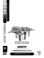
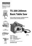
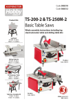
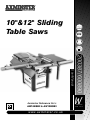
10"&12" Sliding
Table Saws
w w w. a x m i n s t e r. c o . u k
200387/600890
User Manual
Axminster Reference No’s:
AW10BSB2 & AW12BSB2
W
AXMINSTER
W H I T E
Index of Contents...
Page No.
Index of Contents...................................................................................................................... 02
Declaration of Conformity………….………........……..………….......................................... 03
What’s in the Box Part 1-2-3.....……..………….......................................................... 04-05-06
General Instructions for 230v Machines......................................................... 06-07-08
Specifications….………........……..…………...................................................................... 08-09
Initial Assembly Instructions.......................................................................................09
Assembling the Main Saw Bench......................................................................... 10-11
Assembling the Rear Extension Table...................................................................... 12
Mounting the First Side Extension Leaf......................................................................13
Mounting the Slide Rail Assembly....................................................................... 13-14
Mounting the Sliding Table........................................................................................ 14
Mounting the Second Side Extension Leaf...........................................................14-15
Mounting the Front Guide Rail and Rear Clamping Rail for the Rip Fence............ 15
Setting the Machine Tables....................................................................................... 16
Setting the Sliding Table....................................................................................... 16-17
Mounting the Micro-Adjustor to the Rip Fence Mounting Bracket...........................18
Mounting the Sliding Table Fence Assembly...................................................... 18-19
Fitting the Hand Wheels............................................................................................. 19
Fitting the Switch Shroud........................................................................................... 20
Fixing the Riving Knife................................................................................................20
Attaching the Saw Hood Guard and the Extraction Hose....................................20-21
Fitting the Small Mitre Fence..................................................................................... 21
Setting and Checking the Machine...................................................................... 22-23
Identification & Description of the Saw Table...................................... 24-26-28-30-32
Illustration & Parts Description of the Saw........................................... 25-27-29-31-32
W
AXMINSTER
W H I T E
Index of Contents...
Page No.
W
AXMINSTER
W H I T E
Maintenance............................................................................................................... 33
Changing the Saw Blade........................................................................................... 34
Specific Instructions/Precautions for the Saw Bench...............................................35
Parts List/Breakdown for the 10/12" Saw Table....................................36-37-38-39-40
Notes......................................................................................................................41-47
Parts List/Breakdown for the 10/12" Saw Table.....................................42-43-44-45-46
Saf
y Helm
fet
sp irator
Re
Sa
Two
E
R
Ey
fety Viso
Sa
et
st Mask
Du
F ootw
ety
r
Def ende
rs
n
ar
s
ve
ro tectio
eP
tiv e Glo
tec
r
ea
n Asse
Ma
bly
m
al
d Manu
ea
Pro
!
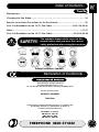
The symbols shown on the cover of this
manual advise that you wear the correct
safety protection when using this machine.
SAFETY!!
Safety Protection Symbols
Declaration of Conformity...
Copied from CE Certificate
The undersigned, F. Nispel authorised
by Laizhou Fulin Machinery Co., Ltd.
No. 275 Wenquan East Road Laizhou, Shandong 261400 P.R. China
declares that this product:
MJ2325A / MJ2325B
Table Saw
manufactured by Laizhou Fulin Machinery Co.is in compliance with
the following standards or standardisation documents in
accordance with Council Directives
EN 61000-3-3: 1995+A1
EN 55014-2: 1997+A1
EN 61000-3-2: 2000
EN 55014-1: 2000+A1
FREEPHONE 0800 371822
03
W
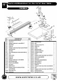
What’s in the Box Part 1...
AXMINSTER
W H I T E
Model Number:
MJ2325A / MJ2325B
Box 1
Saw Body:
1 No.
Saw Table on upper chassis (with motor, table insert, saw blade, NVR switch fitted)
2 No.
Extension Table Leaves
4 No.
Panels to fabricate the lower base ( 2 long 2 short. ( I off short panel has hole
cut out to fit dust extraction duct.)
Packed inside the saw chassis:
1 No.
Adjustable Support Leg (for table extensions) with fixing bolts, nuts and washers
4 No.
Legs
1 No.
Riving Knife
1 No.
Length of 100mm expanding hose
1 No.
100mm extraction duct with integral 30mm manifold and fixing nuts bolts and
washers
1 No.
Top Saw Guard
1 No.
Combined length of 30mm hose
1 No.
Kwick hold down clamp and Tool Post
1 No.
Mitre Fence on bar. ('T' function action by screwed on washers)
1 No.
Packet containing: -- Tommy bar and Stamped Spanner (for blade changing)
1 No.
Switch Shroud with securing screws.
2 No.
Engineers Hand Wheels.
1 No.
Length Gauge Stop for slide table fence.
1 No.
Mitre Angle Rear Quadrant for slide table fence (with 2 No. M8 x 20mm caphead
bolts) and clamping handle fitted.
2 No.
Height Adjusting Blocks (for slide rail mounting brackets)
2 No.
Rear Extension Table Brackets.
For assembling main Dust Extraction Hose and Top Guard Hose
1 No. Packet containing :-
04
2 No.
125mm Jubilee Clips
2 No.
40mm Jubilee Clips
www.axminster.co.uk
What’s in the Box Part 2...
W
AXMINSTER
W H I T E
For assembling Lower Base Legs and Panels, rear extension table
Pkt containing:
12 No.
M8 x 20mm Hexhead Bolts, Nuts and 2 x Washers (Fixing panels)
4 No.
M8 x 20mm Caphead Bolts, and Washers (fixing rear table brackets)
Pkt containing:
4 No.
M8 x 20mm Hexhead Bolts, and Washers (fixing rear table to brackets).
8 No.
M8 x 20mm Hexhead Bolts, nuts and 2 x Washers (fixing legs and panels)
Pkt containing :
2 No.
Clamping Straps (for mounting rear extension table brackets)
Pkt containing:
1 No. 2.5mm Allen Key
1 No. 6mm Allen Key
1 No. 3mm Allen Key
1 No. 8mm Allen Key
1 No. 4mm Allen Key
2 No. 13 mm A/F Spanners
1 No. 5mm Allen Key
Box 2 (Fence and Fixings)
1 No.
Rip Fence Assembly (Partially assembled)
1 No.
Rip Fence Front Rail
1 No.
Rip Fence Rear Clamping Rail
1 No.
Fence assembly for sliding table with (telescopic extension)
Pkt containing :
Micro-adjusting mechanism for rip fence
Pkt containing:
2 No.
Profiled Capping Plates for ends of rip fence mounting bracket
2 No.
Profiled Capping Plates for ends of front fence rail
8 No.
4mm round head self tapping screws
FREEPHONE 0800 371822
05
W
What’s in the Box Part 3...
AXMINSTER
W H I T E
Pkt containing:
10 No.
M8 x 25mm Square Head Bolts, nuts and washers (fixing fence rails)
4 No.
M8 x 20mm Hex Head Bolts and washers (fixing inner extension leaf)
4 No.
M8 x 30mm Hex Head Bolts, nuts and 2 x washers (fixing outer extension leaf)
Box 3
1 No.
Slide Rail assembly for sliding table
Box 4
2 No.
Mounting Brackets for Slide Rail Assembly
1 No.
Sliding Table (with Bearing Bogies assembled)
1 No.
Rear extension table top
1 No.
Manual
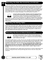
General Instructions for 230v Machines...
Good Working Practices/Safety
The following suggestions will enable you to observe good working
practices, keep yourself and fellow workers safe and maintain your
tools and equipment in good working order.
!
WARNING!!
KEEP TOOLS AND EQUIPMENT OUT
OF THE REACH OF YOUNG CHILDREN
Mains Powered Tools
Primary Precautions
These machines are supplied with a moulded 13 Amp. Plug and 3 core power cable. Before
using the machine inspect the cable and the plug to make sure that neither are damaged. If
any damage is visible have the damaged item inspected/repaired by a suitably qualified
person. If it is necessary to replace the plug, it is preferable to use an 'unbreakable' type
that will resist damage on site. Only use a 13 Amp plug, and make sure the cable clamp is
tightened securely. Fuse as required. If extension leads are to be used, carry out the same
safety checks on them, and ensure that they are correctly rated to safely supply the current
that is required for your machine.
06
www.axminster.co.uk
General Instructions for 230v Machines...
W
AXMINSTER
W H I T E
Work Place/Environment
The machine is not designed for sub-aqua operation, do not use when
or where it is liable to get wet. If the machine is to be used outside and
it starts to rain (unusual though this would be in U.K.), stop work and
move it inside. If machine has got wet; dry it off as soon as possible, with a
cloth or paper towel.
DO NOT use 230v a.c. powered machines anywhere within a site area that is flooded or
puddled, and do not trail extension cables across wet areas.
Keep the machine clean; it will enable you to more easily see any damage that may have
occurred. Clean the machine with a damp soapy cloth if needs be, do not use any solvents
or cleaners, as these may cause damage to any plastic parts or to the electrical
components.
Keep the work area as uncluttered as is practical, this includes personnel as well as
material.
!
UNDER NO CIRCUMSTANCES SHOULD CHILDREN BE
ALLOWED IN WORK AREAS
It is good practice to leave the machine unplugged until work is about to commence, also
make sure to unplug the machine when it is not in use, or unattended. Always disconnect
by pulling on the plug body and not the cable. Once you are ready to commence work,
remove any tools used in the setting operations (if any) and place safely out of the way.
Re-connect the machine. It is also recommended that you use switched supply outlets.
Carry out a final check e.g. check the cutting tool, drill bit, saw blade etc., is securely
tightened in the machine, check you have the correct speed and function set, check that the
cutting path of the timber is unobstructed, etc.,
Most machines these days are fitted with NVR contact switches so that machines cannot
remain inadvertently switched 'ON'. However, it is a good habit to train yourself to check that
the machine is not 'Switched On' prior to connecting the mains supply. (In case you happen
to be using one of the older machines).
Make sure you are comfortable before you start work, balanced, not reaching etc.,
If the work you are carrying out is liable to generate flying grit, dust or chips, wear the
appropriate safety clothing, goggles, gloves, masks etc., If the work operation appears to be
excessively noisy, wear ear-defenders. If you wear your hair in a long style, wearing a cap,
safety helmet, hairnet, even a sweatband, will minimise the possibility of your hair being
caught up in the rotating parts of the machine, likewise, consideration should be given to
the removal of rings and wristwatches, if these are liable to be a 'snag' hazard.
Consideration should also be given to non-slip footwear, etc.
DO NOT work with cutting or boring machines of any description if you are tired, your
attention is wandering or you are being subjected to distraction. A deep cut, a lost fingertip
or worse; is not worth it!
FREEPHONE 0800 371822
07
W
General Instructions for 230v Machines...
AXMINSTER
W H I T E
DO NOT use this machine within the designated safety areas of flammable
liquid stores or in areas where there may be volatile gases. There are very
expensive, very specialised machines for working in these areas, THIS IS
NOT ONE OF THEM.
Check that cutters, drills, blades etc., are the correct type and size, are undamaged
and are kept clean and sharp, this will maintain their operating performance and lessen the
loading on the machine.
If possible always fit dust extraction to machines that are producing high rates of sawdust,
shavings, chips etc.
Above all, OBSERVE…. make sure you know what is happening around you, and USE
YOUR COMMON SENSE.
REMEMBER, YOU ARE ULTIMATELY REPONSIBLE FOR YOUR OWN SAFETY
THIS MACHINE IS DESIGNED TO CUT TIMBER AND TIMBER DERIVATIVE
PRODUCTS. DO NOT use for any other materials.
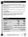
Specification...
Axminster No.
Motor Single phase 230V, 50 Hz:
Blade Speed:
Blade Diameter:
Bore Size:
AW10BSB2
AW12BSB2
200387
600890
2.2kW
3kW
2840rpm
2840rpm
10" (254mm)
12" (315mm)
30mm
30mm
10" (560mm x 800mm) 12" (560mm x 845mm)
Table Size:
Table Size with 2 side extensions
fitted(305 X 800 ea.):
W 1170mm x D 800mm W 1480mm x D 800mm
Table Size with rear extension fitted
(boundary dimensions):
Sliding Table Dimensions:
Continues on next page....
08
www.axminster.co.uk
W 1170mm x D 1500mm
500mm x 400mm
Specification...
W
AXMINSTER
W H I T E
Maximum throat before the Saw with slide rails fully forward:
1220mm
Supported length behind the saw blade:
900mm
Table height:
845mm
Tilt Angle:
0-45 degrees
Minimum Kerf:
3mm
Maximum Depth of Cut (at 90˚ degrees):
AW10BSB2 (75mm) or AW12BSB2 (100mm)
Maximum Depth of Cut (at 45˚ degrees):
AW10BSB2 (60mm) or AW12BSB2 (75mm)
Noise measurements to EN 50144
Lpa (sound pressure):
dB(A)
Lwa (acoustic power):
Weight:
!
99.5
dB(A) 112.5
10" (260kg) or 12" (312kg)
IT IS RECOMMENDED THAT YOU WEAR EAR
PROTECTION WHEN USING THIS MACHINE
Initial Assembly Instructions...
Please read through the Section entitled Parts identification and Description, this will enable
you to more readily identify those parts of the saw to which we will be referring.
TWO PERSON
SYMBOL
PLEASE NOTE. Some of this assembly procedure is best accomplished
by two persons. Although the tasks are not impossible, some of the
items are heavy and awkward, and a mishandling error could cause
injury. Please think about what you are doing, your capabilities and your
personal safety. We have added the 'two person symbol' to any
operation that we recommend should be a two person task.
You will require: A cross point screwdriver in addition to the tools supplied
Unpack all the boxes and check all the components against the “What's in the Boxes' List. If
any parts or components are missing, please contact our customer services department
using the procedures and telephone numbers listed in our catalogue, and you will be dealt
with quickly and efficiently.
PLEASE NOTE: that, on occasion, the packing list is not strictly adhered to, please check
all the boxes, packets etc, to make sure that all the parts have been accounted.
FREEPHONE 0800 371822
09
W
Assembling the Main Saw Bench...
AXMINSTER
W H I T E
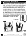
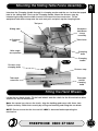
Having unpacked the boxes, (please dispose of any unwanted packaging responsibly), put
the parts and components whereby they are readily to hand. Break down the main box by
knocking the sides away (be careful of exposed nails etc.), but leave the machine sitting on
its pallet. (See fig 1). Identify the short rear panel with the dust extraction cutout, locate the
dust extraction moulding and fit to the panel using the nuts and bolts provided. (See fig 3)
(The orientation of the moulding should leave the 30mm outlet pointing upwards i.e.
pointing up the long length of the panel).
Put the panel aside, and locate the remaining three panels, the lower chassis legs and 20
No. M8x20mm bolts, nuts and double washers. Fix the lower legs to the upper legs using a
washered bolt through the legs and secure with washer and nut, only turn the nuts up
finger tight at this time. (See figs 2 & 2a) Take up the rear panel with the dust extraction
moulding fitted and fit between the rear legs, using washered bolt through the leg and panel
and securing with washer and nut. Again, secure the nuts finger tight only. With easy open
access, now is a good time to fit the dust extraction hose. Locate the hose and the two large
jubilee clips. Stretch the hose out to its full length. Slip the jubilee clips over the ends of the
hose, fit the hose to the outlet on the saw box and the dust extraction moulding and clamp
in place with the clips.(See fig 3)
Fit the remaining panels to the legs, using the same securing sequence. Wriggle, push, pull,
press, lever etc., the legs and the panels into the best alignment with the upper chassis and
tighten the nuts and bolts using the spanners provided. When
everything is tightened up, the machine can now be tipped over,
towards its blind face (as seen in fig 4) until it is resting on the pallet
with its legs on the floor. Lift the machine upright. (See fig 5)
M8x20mm bolts, nuts
and double washers
Upper leg
Lower leg
Fig 1
Fig 2a
Fig 2
10
www.axminster.co.uk
Assembling the Main Saw Bench...
Rear panel with the dust
extraction moulding fitted
Dust extraction moulding
W
AXMINSTER
W H I T E
Fig 3
Extraction hose
Front panel
Fig 4
Fit the remaining
panels to the legs
Blind face
Fig 5
Dust extraction outlet
FREEPHONE 0800 371822
11
W
AXMINSTER
W H I T E
Assembling the Rear Extension Table...
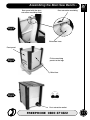
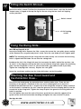
Remove the 6 fixing bolts in each of the two top, side panels, put carefully aside and
remove the panels. (See figs 6 & 7) This gives easier access to the back of the two rear
upper chassis legs. Locate the rear extension table brackets, the clamping straps and 4 No.
M8 caphead bolts and washers.
PLEASE NOTE: the manufacturer has fitted adjusting bolts to the brackets, these are the
faces that back against the legs.
Offer the clamping plates up to the inside face of the legs, fasten the bracket using
washered bolts through the bracket and the leg into the clamping strap. Tighten the bolts
finger tight only at this time. (See figs 7,8). Locate the table and the other 4 No. M8
caphead bolts and washers. Mount the table onto the brackets,
Note: that the securing bolts need to feed through the elongated holes in the bracket. (the
extension table is spaced off the main table to allow clearance for the rear clamping rail and
the rip fence). Leave all bolts finger tight at this time.
Side panels removed
Fig 6
Fig 7
Inside face of the leg
Table bracket
Fig 8
M8 caphead bolts
and washers
Fig 9
Table fixing
holes
Mount the table onto the brackets
12
www.axminster.co.uk
Mounting the First Side Extension Leaf...
W
AXMINSTER
W H I T E
!
THE EXTENSION LEAF IS HEAVY YOU MAY REQUIRE
A SECOND PERSON TO HELP LIFT IT IN PLACE
Select one of the extension leaves, (either one, they are identical) locate 4 No. M8 hexhead
bolts and washers. Ensure the table is correctly orientated (the front edge of the table is
bevelled). Stand the back end of the table on the floor, close to the front and edge of the
main saw table, with the underside of the table facing the front of the saw. Lift the table up
and introduce a washered bolt through the first hole in the leaf and screw it into the first
threaded hole along the main table edge.
Screw the bolt in until it is almost home. You can now relax the lifting effort. The extension
will hang pivoted on the bolt. Carefully lift the bottom end of the extension up until the
edges are level and introduce a washered bolt through the rear hole and the last threaded
hole in the table edge, screw it almost home. The extension should be hanging in
approximately its correctly position held by the two bolts. Introduce and almost screw home
the other two washered bolts. Align the top and front edges at the front of the saw, 'nip' the
front bolt to hold the extension in place; carefully manoeuvre the rear of the extension to
align the two top edges and 'nip' the rear bolt. Check this movement has not disturbed the
alignment at the front of the table, if it has, repeat the procedure until the front and top
edges are aligned. Tightened all the bolts securely.
Mounting the Slide Rail Assembly...
Fig 10
Fig 11
Mounting
bracket
Height
adjustor
block
Cuphead
bolt
Side rail assembly
unscrew the caphead bolt in the height
adjustor block until the recessed
hole for the fixing bolt is clear
Locate and identify the mounting brackets and the height adjustor blocks. (See figs 10 & 11)
These are mounted on the outside faces of the upper chassis legs. They are anchored
against clamping plates that are behind the face of the legs.
NOTE: These clamping plates are 'loose items', each is initially held in place by three
pre-introduced fixing bolts. It is suggested that you do not remove all these bolts at the
same time. The suggested procedure is:- unscrew the caphead bolt in the height adjustor
block until the recessed hole for the fixing bolt is clear, remove the lowest bolt; fit it through
the height adjustor block and screw it back into its position. Screw it almost home. Remove
the top bolt, fit it through the top hole of the bracket, and with the bracket tilted to one side,
screw it back into its position.
FREEPHONE 0800 371822
13
W
Mounting the Slide Rail Assembly (Continued)...
AXMINSTER
W H I T E
Remove the middle bolt, allow the bracket to hang vertically, fit the bolt through the bottom
hole of the bracket, screw it back into its position. Align the adjustor block as near vertical
as you can judge and fasten up its fixing bolt. Screw the adjusting bolt back through the
block until it touches the lower face of the mounting bracket. 'Nip' the securing bolts for the
mounting bracket. Fit the other bracket in the same way. When screwing the adjusting bolt
back through the block, set it to leave the brackets at approximately the same height.
Unscrew the slide rail assembly locking dogs so they have plenty of movement.
Locate the slide rail assembly, orientate it so that the longest rail is at
the top, and the channels etc., of the extrusion are underneath. Offer it
up to the front bracket and introduce the locking dog into the main
channel in the extrusion. The two open channels should fit over the
guide lands on the bracket face. Slide the assembly forward and repeat
the procedure with the rear bracket. Slide the assembly forward until it is set approximately
equi-distant about the brackets; tighten the lift and shift lever handled bolts to 'pinch' the
slide in place.
Mounting the Sliding Table...
Remove the safety stop and the 'rubber buffer ring' at the end of the top rail, place carefully
aside. Locate the sliding table and manoeuvre the bearing bogies onto the rails, slide the
table onto the rails and position it safely within the boundary of the table. Ensure that the
initial setting of the slide rail assembly will not cause the sliding table to collide with the
main table. Replace the buffer ring and the safety stop.
Mounting the Second Side Extension Leaf...
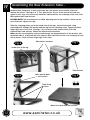
Locate the second extension leaf, the table extension support leg, 2 No.
M8 x 20mm hexhead bolts, washers and nuts, and 4 No. M8 x 30mm
hexhead bolts, washers and nuts. Orientate the leaf correctly. Establish
which will be the outer edge.
Turn the leaf upside down on a work surface (or the saw table) and attach the support leg to
the outside edge, using the 20mm bolts and fastening through the two middle holes. Fasten
securely.(See fig 12) Re-right the leaf and fix to the first extension table, using the same
procedure as before. Note. This leaf is fixed using washered 30mm bolts, through both
edges and secured with a washer and nut. YOU MUST ENSURE THAT THE NUT IS FULLY
ENGAGED ON THE BOLT BY SEVERAL TURNS, BEFORE YOU RELAX THE LIFTING
EFFORT. Proceed to fit the other bolts and align the table as before. Tighten all bolts
securely.
Unlock the clamping bolt of the support leg and allow the inner section to slide through until
the foot is resting on the floor. Do not put the leg under tension at this time. 'Nip' up the
clamp bolt.
14
www.axminster.co.uk
Mounting the Second Side Extension Leaf...
W
AXMINSTER
W H I T E
Second
extension leaf
Fig 12
Support leg
M8x20mm
hexhead
bolt
Turn the leaf upside down on a work surface (or the saw table?)
and attach the support leg to the outside edge, using the 20mm
bolts and fastening through the two middle holes.
Mounting the Front Guide Rail and Rear
Clamping Rail for the Rip Fence...
Locate the 10 No. M8 SQUARE head bolts washers and nuts. We have ascertained the best
way to fit the rails is to introduce the bolts through the holes in the front and rear edges of
the tables, hold in position by adding the washer and fitting the nut a couple of turns onto
the bolt. Select the front guide rail and introduce the square head of the furthest right hand
bolt into the channel in the extrusion; slide the rail along the front of the machine picking up
all the bolt heads as you go along. (See fig 13) Reach under the table edge and finger
tighten all the nuts. Repeat the process for the rear rail.
Locate the capping plates for the front rail and fit carefully using the self tapping screws.
(See fig 14) Set the front rail in position, remembering that it must be slightly inside the front
left hand edge of the main saw table, so that the sliding table does not collide with it.
Tighten ONLY the 3 bolts in the main saw table. Repeat the process for the rear rail (without
the capping plate operation!).
Fig 14
Fig 13
FREEPHONE 0800 371822
15
W
Setting the Machine Tables...
AXMINSTER
W H I T E
PLEASE ENSURE THAT BY NOW, THE SAW BENCH IS PLACED IN ITS WORKING
LOCATION IN THE WORKSHOP.
Place a long straight edge (as long as ext. table plus 2/3 main saw table min.) along one
long edge of the rear table and along the main table.
NOTE: The rear extension table brackets can be moved up and down within the slotted
fixing holes, and 'tilted' forward or backward using the adjusting bolts in the frames adjacent
to the fixing bolts. Remember to loosen or tighten the adjacent fixing bolt if you are moving
an adjusting bolt.
Make sure all the fixing bolts are generally finger tight. Set the near corner of the table to
the straight edge, by pushing, pulling, tapping etc. 'Nip' the securing bolts. Move the
straight edge to the other edge of the extension table, repeat the procedure. Now, if
necessary, adjust the 'tilt' to bring the far corner up to the straight edge, tapping the near
edge down (or up), if necessary. Move the straight edge back to the original edge and
repeat the procedure. When the table is set tighten the fixing bolts securely. THEN check
the table again. Repeat any part of the procedure if necessary.
Place the straight edge across the table and the two extension leaves. (There may be some
slight 'sag' at the outer most edge of the leaves due to their weight). If there is any 'falling
off' adjust the table support leg to correct this. When you are satisfied that the main table
and the side extension leaves are in plane tighten the remaining 4 bolts that secure the front
and rear rails.
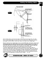
Setting the Sliding Table...
NOTE 1. With the bracket fixing bolts in a 'loose' condition ensure that the slide rail
assembly is clamped flat to the brackets. Retighten the fixing bolts 'finger tight'.
NOTE 2. The slide rail mounting brackets can be moved up and down within the slotted
fixing holes, using the height adjusters and 'tilted' forward or backward using the adjusting
bolts in the frames adjacent to the fixing bolts. Remember to slacken the fixing bolts off if
you are adjusting the height, or carrying out a dramatic alteration , otherwise you may
stress the bracket casting; loosen or tighten the adjacent fixing bolt if you are moving a 'tilt'
adjusting bolt. Remember also that the final 'tighten' of the fixing bolts may alter the setting
slightly. Re-check all settings after the final tightening.
The overall setting process is done in 3 phases. 1) Setting the table level against the main
table; front and rear. 2) Setting the sliding table/main table gap, to ensure a parallel feed.
3) Raising the sliding table slightly 'proud' of the main table. The reason it is done in this
manner and this order, is that phases 1) and 2) are interactive e.g. tilting the sliding table to
bring it level can change the gap between the two tables, (See fig 15) whereas if the tables
are set level a uniform adjustment to the brackets, should not alter the level, merely the gap.
(See figs 15 & 16) The final phase is only a 'jacking' exercise and should not affect the
previous settings.
Make sure all the fixing bolts are generally finger tight.
16
www.axminster.co.uk
Setting the Sliding Table...
W
AXMINSTER
W H I T E
Fig 15
Fig 16
Set the sliding table so that the front edge is inline with the front edge of the saw table.
Place a long straight edge (a bit more than twice the width of the sliding table) along the
front edges of the two tables. Set the near corner of the table to the straight edge.
Move the table and the straight edge to the rear of the MAIN table. Set the rear corner to the
straight edge. Adjust the table to bring it level under the straight edge. Move the table and
the straight edge back to the front of the main table and check the table is level; adjust if
necessary. Once you are satisfied, and all the bolts are now 'nipped', slide the table back
and forth and check the gap between the sliding table and the main table.
It should be approximately 2-3mm and uniform alongside the main table. Adjust as
necessary, making uniform adjustments of the bolts in each bracket. Again, when you are
satisfied; 'jack' the table up by screwing both the height adjusting bolts UP approximately
3/4 turn. This will raise the table by something less than a millimetre and will reduce the
drag of the workpiece at the main table edge, giving easier, more controllable movement.
Check all bolts are tightened up, recheck all your settings…….etc. etc.
FREEPHONE 0800 371822
17
W
AXMINSTER
W H I T E
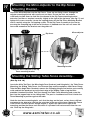
Mounting the Micro-Adjustor to the Rip Fence
Mounting Bracket...
Locate the Micro-Adjustor and the Rip Fence. There are two fixing screws through the
adjustor mounting bracket with square nuts on them. Ensure the nuts are undone
sufficiently to allow them to slide into the channel in the Rip Fence mounting bracket
extrusion, position as required, normally slightly to the right of the rip fence, (See fig 17) and
tighten the screws securely. Locate the capping plates for the Rip Fence Mounting Bracket
and fit carefully using the self tapping screws. Fit the Rip Fence assembly to the saw by
ensuring the clamping lug at the rear of the fence is 'hooked over' the rear rail, lower the
fence and manoeuvre the bracket over the guide rail.
Fig 17
Micro-adjuster
Rip fence
Mounting bracket
Fitting the micro-adjuster to the rip
fence mounting bracket
Mounting the Sliding Table Fence Assembly...
(See fig 18 & 19)
Locate the Main Tool Post, the Mitre Angle Rear Quadrant (and fixing bolts), the Table Fence
Mounting, the Sliding Table Fence, the Distance Stop and the workpiece Hold Down Clamp.
Take the Mitre Angle Rear Quadrant, remove the Clamping Handle and washer, put carefully
aside and bolt the quadrant on to the front edge of the Sliding Table using the bolts
provided. Introduce the Main Tool Post through the Table Fence Mounting and screw the
post into the tapped hole in the sliding table. The post is shouldered such that it holds the
Fence Mounting in position against the table.
Undo the two fence mounting bolts such that the dogs on the front surface have sufficient
movement to be able to be slid into the extrusion in the rear of the fence. Mount the Fence
such that the sacrificial plastic orange tongue is against the table to the right of the
mounting; position the fence such that when it is pivoted it will not encroach into the saw
slot. Pinch up the fixing bolts.
18
www.axminster.co.uk
Mounting the Sliding Table Fence Assembly...
W
AXMINSTER
W H I T E
Introduce the Clamping Handle through its clamping washer and the arc slot into the tapped
hole in the sliding table. Pinch up the Clamping handle. Mount the distance stop by
introducing the dog into the wide channel in the top of the fence extrusion. Fit the
workpiece hold down clamp onto the main tool post and pinch up the clamping knob.
Tool post
Fig 18
Sliding table
Workpiece
hold down
clamp
assembly
x2 Caphead
bolts
Table fence
Mitre angle
rear quadrant
Clamping
knob
Clamping
handle
Fig 19
Distance stop
clamping knob
Distance stop
Telescopic
extension
Telescopic
section
clamping
knob
Fitting the Hand Wheels...
Locate the two hand wheels. Fit the hand wheels onto the shafts for the tilt mechanism drive
and the rise and fall mechanism.
Note: the square key slots on the shafts, align the holding grubscrews with these slots.
Tighten securely. Check their security by raising and lowering and tilting the saw blade.
NOTE. Please ensure that the rise and fall LOCK is loosened before operating the
mechanism.
FREEPHONE 0800 371822
19
W
Fitting the Switch Shroud...
AXMINSTER
W H I T E
Locate the switch shroud. Position the shroud over the switch block, such that the knob
shaped cover is hinged at the top See fig 20. Secure using the two small self tapping
screws provided.
Switch shroud
Fig 20
x2 Self tapping
screws
Fixing the Riving Knife...
See IPB on Page 42 & 43
Locate the Riving Knife. Remove the 5 No. screws that secure the saw gullet, place carefully
aside. Remove the saw gullet and place it aside. Raise the saw blade up to its highest point.
NOTE: The mounting plate for the riving knife has been factory set to ensure that the riving
knife is aligned with the blade. Do not alter the setting bolts.
Introduce the slot in the riving knife over the two centre line bolts, behind the washers, (no.
16 and 11 in the diagram) and nip the bolts to just hold the riving knife against the mounting
plate. Set the riving knife so that it is close to the blade, (gap about 2-3mm if possible).
Tighten the clamping bolts securely. Replace the saw gullet.
Lower the saw blade, making sure the riving knife does not foul the gullet.
Attaching the Saw Hood Guard and
the Extraction Hose...
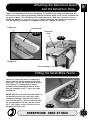
Locate the saw hood guard, the extraction hose and the jubilee clips. There are two
fastenings in the guard, a fixed bolt at the rear and a clamping bolt just in front of it.
Introduce the fixed bolt into the 'L' shaped slot in the riving knife and push it down and back
so that the bolt is locked into the slot. Lower the guard so that the clamping bolt fits into the
curved slot in the riving knife. Tighten the clamp to pinch the guard to the riving knife and
hold it in position.
Push the jubilee clips over the ends of the hose, push the hose onto the spigots of the
guard and the main dust extraction moulding and tighten the clips to hold it in place.
See figs 21 & 22
20
www.axminster.co.uk
Attaching the Saw Hood Guard
and the Extraction Hose...
W
AXMINSTER
W H I T E
There is no requirement to remove the guard. The profile of the riving knife precludes the
use of the saw for slotting or grooving, and the maximum depth of cut can be achieved with
the guard in place. The positioning of the extraction hose could be a nuisance if you are
cutting big boards, et al. In such a case it is better to remove the hosing from the guard,
than risk getting the workpiece snagged and perhaps 'slewing' on the saw.
Jubilee clip
Hood guard
Fig 21
Extraction
hose
Fig 22
Riving knife
Dust extraction
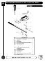
Fitting the Small Mitre Fence...
Locate the small mitre fence. Introduce the
nose of the bar into the required slot in the
main table. Lay the bar flat and push forward.
The 'locking T' is produced by a washer
screwed to the underside of the bar, make
sure this engages in the 'T' slot in the table.
(See fig 23)
NOTE: With the rear extension table fitted it is
not possible to push the small mitre fence
completely 'through'. However, the travel is
such that the fence is able to travel well past
the cutting edge of the saw, and the rear of
the 'T' slot is open so that saw dust can be
pushed clear of the slot.
Fig 23
FREEPHONE 0800 371822
21
W
AXMINSTER
W H I T E
Setting and Checking the Machine...
Raise the blade to its maximum height, check that is upright to the table. Set the sliding
table fence to zero angle against the preset post. Slacken the two fence mounting bolts and
slide the fence up close to the saw blade. Fasten the two mounting bolts again.
Using a known 90˚ square place it against the fence and the blade (not on the teeth), and
check that the angle is correct, if not, adjust the preset post on the Mitre Angle Rear
Quadrant. (See fig D) This preset post is a small eccentric cam mounted on the shaft of a
caphead bolt. By loosening the bolt and turning the head of the post with a spanner, the
position of the stop can be altered.
Check the angle again, continue to check and adjust until it is correct. Pivot the fence to the
45˚stop. Using a mitre square; et al, check the angle. Repeat the procedure as previously.
Reset the saw to zero angle.
Loosen the fence mounting bolts, slide the nose of the fence (the orange tongue) up to the
blade, secure. Check the parallelity of the sliding table movement by sliding the table
forward and checking the tongue/blade are still in contact, or that the movement has not
jammed the tongue against the saw. If there is a slight discrepancy, it may be acceptable to
you. (a 1mm difference across the face of the blade (fully extended) is about (one quarter of
a degree) and pro rata. If not, or the discrepancy is too large, the slide rail assembly will
need to be re-adjusted, to achieve a parallel motion.
Set the distance stop to a predetermined measurement against the inset scale. Loosen the
fence mounting bolts and using a tape or a distance piece set the fence so that the saw
blade to stop is that measurement. Tighten the mounting bolts securely.
Tilt the blade fully over. Using a mitre square et al; set the angle of the saw to 45˚. Check
that the index mark gives a corresponding reading against the scale. Adjust the pointer if
necessary. Reset the blade upright, check that the angle scale reading is correct.
Set the rip fence a predetermined distance from the saw blade and lock in position. Check
that the rip fence is held securely when it is locked in position. If the locking appears a little
'slack' adjust the position of the clamping lug at the rear of the rip fence by tightening the
nut. Check that the preset distance corresponds to the measurement on the scale against
the index mark in the magnifying lens. If not, adjust the position of the rip fence on its
mounting bracket.
Fit the small mitre fence to the machine. Loosen the clamping handle.
NOTE: There are 3 preset positions available with the small mitre fence. +45˚, 0˚, and 45˚, these are achieved using lugs in the casting and a push/pull pin against which the lugs
are stopped. The pin has to be fully withdrawn to allow the fence to pivot from one side to
the other.
Set the face to zero angle using the preset position. Check that the angle is correct (and the
lug is on the correct side of the pin). Check that the indexing pointer gives the correct
reading against the scale. Adjust the pointer if necessary. Check left and right positions.
Check the pointer is still correct. If the preset positioning is wrong, set the fence with a
square/mitre gauge, set the pointer accurately against the scale, and clamp the fence in
position without recourse to the presets.
Remove the small mitre fence from the table and stow carefully aside.
22
www.axminster.co.uk
Setting and Checking the Machine...
W
AXMINSTER
W H I T E
Check the belt tension (see fig 24) the belt should be tight, but not unduly so.
Remove all tools and stow away. Check that the machine tables are clear. Lower the saw to
leave about 25mm protruding, set the saw upright.
Check that everything that should be tight, is tight; saw blade guard, rise and fall lock
mechanism, fence clamps etc.
Connect the machine to the mains supply, lift the switch shroud and give the machine a
quick burst. i.e. On/Off. Check that everything is sound and feels O.K. (No knocking,
scraping, belt squeal, rubbing etc.,)
Give the machine a longer run, and 'slap' the switch shroud down. Check that this gives a
fast and easy method of switching the machine off, without searching for the stop switch
button.
When you are happy that everything seems O.K. switch the machine off, disconnect from
the Mains Supply. Locate the two upper side panels and their fixing bolts and secure them
in place.
Congratulations; one 10” bench saw; assembled and ready to work.
Belt
Fig 24
Belt tensioner bolt
FREEPHONE 0800 371822
23
W
Identification & Description of the Saw Table...
AXMINSTER
W H I T E
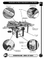
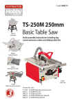
Saw table
(See fig A)
This is the actual machine, it comprises a cast iron table with the cut-out
to allow the saw blade to project through, the two slots into which the
small mitre fence can be fitted. The edges of the table have various
combinations of drilled and tapped holes to allow the mounting of the
extension tables and the fence mounting rails; the saw assembly and the
motor are bolted to the underside of the table. The saw assembly
comprises the saw shaft with its rise and fall and tilt mechanism. The
drive is provided by the motor pulley via a drive belt to the saw shaft.
The saw table is bolted into the tops of the legs of the Upper Chassis
using 4 adjustable bolts and locking nuts to enable the table to be set
correctly. The table has been factory set, and unless it is significantly
'out' should not be adjusted.
Upper chassis
(See fig A)
The Upper Chassis comprises 4 steel fabricated legs and 4 pressed
steel panels bolted in position between them. The two upper side
panels are mounted to the chassis frame such that they can be
removed, to allow access to the saw assembly, the motor, the drive belt
etc.; these panels are each held in position by 6 caphead bolts. The
Front panel has two cutouts for the rise and fall drive shaft and the
locking mechanism actuator to come through. The cutout for the rise
and fall shaft has a decal applied to the lower edge to enable the angle
of the saw tilt to be read off, using an index pointer mounted on the saw
mechanism.. The front right leg mounts the drive shaft for the tilt system.
The NVR ON/Off Switch plate is mounted on the upper left front leg.
Lower chassis
(See fig A)
This comprises a further 4 steel fabricated legs and 4 pressed steel
panels bolted in position between them. The lower rear panel has a
cutout to allow the mounting of the dust extraction moulding.
Table insert
(See fig A)
This is a metal alloy insert that covers the hole in the saw table through
which the blade protrudes, and which allows access to the inside of the
saw table, to enable the riving knife to be adjusted, the saw blade to be
changed, et al. The left side of the gullet has been relieved so that the
saw blade can be tilted.
Extension tables The cast iron extension tables provide added support for the workpiece
(See fig A)
beyond the boundaries of the saw table to the rip side.
24
Extension table
support leg
(See fig A)
Because of the weight of the extension leaves, a support leg is provided
to increase stability. The height adjustment is effect by loosening the
caphead bolt and allowing the inner channel to slide in the outer
channel. Tighten the bolt to lock the leg at the height selected.
Rise and fall
control hand
wheel
(See fig A)
This is an engineers wheel handle attached to the shaft of the rise and
fall mechanism of the saw. Turning the handle clockwise will cause the
saw blade to rise, anti-clockwise to fall. Rotate control behind clockwise
to lock spindle.
Tilt angle
lock
(See fig A)
A small star knob situated above the rise and fall control handle that
locks the tilt mechanism to prevent any movement that could be caused
by vibration during the saw operation.
www.axminster.co.uk
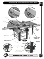
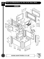
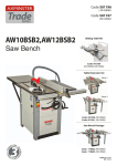
Illustration & Parts Description of the Saw...
Table insert
W
AXMINSTER
W H I T E
Riving knife
Extension
table
Saw Table
'T' slot
Extension
table
Upper chassis
Extension table
support leg
Fig A
Lower chassis
Tilt angle lock
Tilt control
hand wheel
Rise and fall control
locking handle
Rise and fall
control hand wheel
FREEPHONE 0800 371822
25
W
Identification & Description of the Saw Table...
AXMINSTER
W H I T E
Tilt control
hand wheel
(See fig A)
This is an engineers wheel handle attached to the shaft of the tilt
mechanism of the saw. Turning the handle clockwise will cause the saw
blade to return upright, anti-clockwise to tilt it right. There is not
locking function on the tilt mechanism assembly.
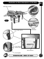
Tilt angle scale
(See fig B)
This is a self adhesive scale decal that is stuck onto the front of the
machine to give some indication of the angle to which the saw blade is
tilted.
On/Off switches Two grouped switches that control the NVR contactor of the saw table,
(See fig B)
They carry the standard markings of 'I' for ON and 'O' for OFF. There is a
shroud that fits over the switch block, with a cover shaped as an
emergency stop button. Moulded on the rear of the cover is a protrusion
that impinges on the stop button. If the guard is locked down, the stop
button is permanently depressed. If, whilst you are operating the saw
you should require to stop the machine quickly; 'slapping' the cover
down will depress the stop button.
26
Blade guard
(See fig B)
A moulded plastic guard that is mounted on the riving knife. There is a
30mm dust extraction port at the rear of the guard which can be
connected to the main dust extraction ducting at the rear of the saw, or
connected directly to an extraction system as you choose.
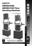
Rip/guide fence
mounting rail
(See fig B)
A section of extruded aluminium rail that fixes onto the front edge of
the sawtable, it also extends across the faces of the extension leaves,
so that the rip fence can be used across the full width of the saw. The
rail carries a scale tape, to enable the distance to the fence to be
gauged. The front of the extrusion forms the moulded shape into which
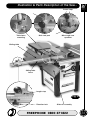
the rip fence mounting fits and locks. The underside of the mounting rail
had a toothed rack fixed to it, for use with the micro-adjustor of the rip
fence.
Mounting rail
capping plates
Two lamina plates shaped to the extruded section of the mounting rail
and secured by self tapping screws. They blank off the voids at the ends
of the rail.
Rear fence
clamping rail
(See fig B)
A section of extruded aluminium rail that fixes onto the rear edge of the
sawtable, it also extends across the extension leaves. The locking lug of
the rip fence clamp pulls up against the rail to hold the fence in position.
Rip fence and
mounting
bracket
(See fig B)
An aluminium box shaped extrusion. The whole is mounted onto the
mounting bracket. The locking handle is pivoted in the front part of the
fence and has a cam action that moves a long rod which pulls the rear
locking lug against the rear fence clamping rail to hold the fence in
position. The mounting bracket is the complementary shape of the
mounting rail and can slide back and forth along the rail. Channels in
the extrusion capture the nuts of the fixing bolts, this allows the fence
and the micro-adjustor to be fastened to the bracket. There is a
magnifying sight glass with an index line recessed into the bracket.
www.axminster.co.uk
Illustration & Parts Description of the Saw...
W
AXMINSTER
W H I T E
Rip fence and
mounting bracket
Blade guard
Rip fence
Rear fence
clamping rail
Rip/guide fence
mounting rail
Fig B
Tilt angle
scale
Emergency
stop button
Off
On
Mounting rail
capping plate
ON/Off switches
FREEPHONE 0800 371822
27
W
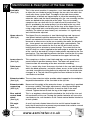
Identification & Description of the Saw Table..
AXMINSTER
W H I T E
Mounting
bracket
capping plates
(See fig C)
Rip fence
micro-adjustor
(See fig C)
28
Two lamina plates shaped to the extruded section of the rip fence
mounting bracket and secured by self tapping screws. They blank off
the voids at the ends of the bracket.
This is a small bracket housing that mounts a small shaft with a round
knob handle on the outer end and a pinion gear on the other. The gear
is held disengaged from the rack on the mounting rail by a spring. If you
wish to use the adjustor, pushing the handle forward against the spring
will allow the pinion to engage with the rack. Precise movement, left and
right can now be achieved. REMEMBER to unlock the fence before
attempting to use the adjustor.
Mitre fence
(See fig C)
A cast assembly, which mounts on to a steel bar. The steel bar fits into
the machined slots in the table. A 'T' bar locking effect is achieved by
screwing a large diameter washer to the underside of the bar. This
washer runs in the thin slots which form a 'T' in conjunction with the
main slot. The assembly at the rear of the mitre fence is a combination
of index marker and preset stop mechanism. Withdrawing and
advancing the locating pin against the various faces in the casting will
establish several preset angular positions. Remember to lock the mitre
fence in position before use. There is a decal scale on the main body of
the mitre fence which will enable you to read off the angle at which the
device is set.
When the rear extension table is fitted, it prevents the mitre fence being
'slid thro' to clear the table at the rear. This should not present any
problems with the functionality of the saw as the mitre fence at any
angle more than adequately passes the front edge of the saw
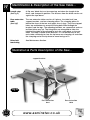
Sliding table
assembly
(See fig C)
The Sliding Table Assembly consists of:-
Slide rail
brackets
(See fig C)
These are cast brackets that are bolted through the face of the legs of
the upper chassis on the off side of the saw. The holding bolts for the
brackets are anchored in a flat clamping plate that is behind the face of
the leg. The brackets are used to mount the slide rail assembly. The
inclined faces of the brackets have two guide lands that engage with the
slide rail assembly to locate it in position. There is also a square dog
that is captured in its corresponding channel in the slide rail assembly,
this dog is tighten in the channel using the lift and shift lever handle; this
will lock the slide rail into position. The brackets are symmetrical and
can be fitted either way 'up'; although, nominally the adjusting bolts are
pre-fitted and would indicate the way the bracket is to be mounted.
Slide rail
bracket
adjusters
(See fig C)
Height
adjusters
(See fig C)
There is an adjusting bolt at the top and bottom of the rear bracket face
to enable the slide rail assembly and hence the sliding table to be set
correctly.
These are two small blocks that bolt to the chassis leg face below the
slide rail brackets. There is a bolt through the block that is driven
against the lower face of the bracket and allows the height of the
bracket and hence the sliding table to be set precisely.
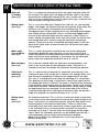
Illustration & Parts Description of the Saw...
W
AXMINSTER
W H I T E
Slide table assembly
Mitre fence
Fig C
Typ. 2 Height adjuster
Rip fence
micro-adjuster
Typ. 2 Slide rail
bracket adjuster
Side rail bracket
Securung bolt
FREEPHONE 0800 371822
29
W
Identification & Description of the Saw Table...
AXMINSTER
W H I T E
30
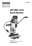
Slide rail
assembly
(See fig D)
This is an aluminium extrusion to which the upper and lower slide rails
are secured. The upper rail is the longer of the two, and has the stops
(to prevent the sliding table coming off the rails) at either end. There is
also an 'O' ring at both ends of the rail, against the stops, to prevent the
roller bearings 'crashing' into the stops.
Sliding table
(See fig D)
This is a cast iron table that is fitted to the slide rails via 3 No. bearing
bogies. Two bogies are fitted to lands on the underside of the table and
the third is on a flange at the bottom of the cantilever leg. This
arrangement gives a wide triangular base area, providing good support
and stability for the sliding table. There is a drilled and tapped hole in
the face of the table into which the main tool post is fitted. There is a
further drilled and tapped hole in the face that accepts the lift and shift
lever handle bolt that is used to clamp the table fence mounting in
position. There are also two small drilled and tapped holes in the rear
apron of the table, which accept the bolts that secure the mitre angle
rear quadrant.
Mitre angle
rear quadrant
(See fig D)
This is a small casting that is bolted to the rear of the sliding table
immediately behind the main tool post. It has a decal laid in it that
allows the angle of the sliding table fence to be measured against the
index mark on the fence mounting. It also mounts the two adjustable
preset stops that enable the fence to be set to 0˚ and 45˚
Main tool post
(See fig D)
This is the post around which the table fence mounting pivots, and
which is the anchor post for the hold down clamp. The post has a
shoulder turned on it that keeps the table fence mounting in position.
Table fence
mounting
(See fig D)
This is a semicircular casting that fits around the main tool post. The
semicircular part of the casting has a radiused slot, through which a lift
and shift lever handled bolt is fitted into the tapped hole in the table.
This acts as a locking device to clamp the mounting at its set position.
The 'diameter' of the casting is raised into a vertical face against which
the sliding table fence is fastened. The fence is fastened to the mounting
using two bolts which engage with the dog plates captive in the channel
of the fence extrusion. The fence extrusion can be set by sliding it along
the dogs before they are clenched. On the outer edge of the circular
casting are two lugs which strike against the preset stops on the mitre
angle rear quadrant to establish the fence at 0˚ or 45˚.
Sliding table
fence
(See fig D)
An aluminium extrusion. This is, in fact, an extrusion within an extrusion,
as the fence can be telescoped out to increase the support length of the
fence, and increase it's measuring capacity, using the tape decals inset
into the grooves in the top of the extrusions. There is a relief in the
inside end of the main fence into which is fitted a nylon block, this block
is the 'soft edge' that is set closest to the saw blade. The top of the
extrusion has a large 'T' slot into which the locking dog for the length
stop is fitted. The secondary extrusion can be locked in position by a
star handled bolt, which clamps the two extrusions together.
Note: Only the END o the extention rail is in the same plane as
the face of the fence.
www.axminster.co.uk
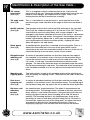
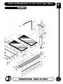
Illustration & Parts Description of the Saw...
Preset stops
Table fence
mounting
Main tool post
W
AXMINSTER
W H I T E
Mitre angle rear
quadrant
Sliding table
Siding table
fence
Length stop
Fig D
Extention lock
Slide rail assembly
FREEPHONE 0800 371822
31
W
Identification & Description of the Saw Table...
AXMINSTER
W H I T E
Length stop
(See fig D)
A 'flip over' blade that can be moved up and down the length of the
fence, and clamped in position. The distance from the blade can be set
against the tape decal.
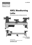
Rear extension
table
(See figE)
The rear extension table consists of 5 pieces, the table itself, two
support brackets, and two clamping plates. The clamping plates fit
behind the faces of the two rear upper chassis legs. They have tapped
holes top and bottom to accept the fixing bolts fitted through the
brackets and the legs. The mounting brackets are symmetrical and can
be fitted either way 'up'. The fixing holes are elongated to allow the
height of the table to be adjusted to be in the same plane as the saw
table. The table is bolted to the brackets. It is set off the back of the
main table sufficiently to clear the rip fence rear clamping rail and allow
the clamping end of the rip fence to move freely past it.
Drive belt
tensioning
See Maintenance Section.
Illustration & Parts Description of the Saw...
support bracket
Fig E
Dust extraction
duct
32
www.axminster.co.uk
Rear extraction
table
Maintenance...
W
AXMINSTER
W H I T E
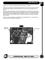
Keep the saw as clean and free from saw dust build up as is practical.
Periodically, remove the saw gullet and blow out brush out clean out the saw box and the
extraction hosing. Remove any resin build up in the saw box, using a proprietary resin
cleaner.
Remove the upper side panels and clean the threaded drive shafts of the rise and fall and
tilt mechanisms. At the same time check the belt drive, i.e. the belt is not 'glazing' with resin
build up, likewise with the pulley wheels. Check the belt tension. If the belt is becoming
slack, loosen the motor hold down bolts and drive the motor backward with its adjusting
bolt. See fig 25.
Check the saw blade regularly for chipped, missing, damaged teeth etc. and remove any
resin build up from the blade, riving knife etc.
Fig 25
Motor hold
down bolts
adjusting bolt
FREEPHONE 0800 371822
33
W
Changing the Saw Blade...
AXMINSTER
W H I T E
!
WARNING!!
DISCONNECT THE MACHINE FROM
THE MAINS SUPPLY
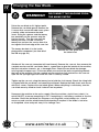
Raise the saw blade to it's highest point.
Remove the saw blade guard. Remove the
5 screws that secure the table insert, place
carefully aside and remove the table
insert. Using the spanner and the tommy
bar provided, put the spanner onto the
flats on the nut. Turn the saw until the
tommy bar hole is visible. Insert the
tommy bar and turn the saw to allow it to
rest against the front edge of the saw slot.
The tommy bar hole is in the inside
platewasher component (see item 92 of
the IPB on page 42.)
Remove the saw guard and
the table insert
Slacken off the saw nut (remember left hand thread). Remove the saw nut, then remove the
sawplate washer and the saw blade. Now is a good time to give the interior of the machine,
the dust extraction channels, etc. a thorough clean. Check the new blade for damage,
missing teeth,sharpness etc. Fit the new blade, ensure that the teeth are pointing towards
the front of the machine. Put the sawplate washer onto the shaft and twist on the saw nut.
Spin the nut up finger tight and check the saw is correctly seated.
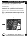
Tighten up the saw nut, using the tommy bar to hold the shaft steady. Check the riving knife
is aligned with the saw blade, and correctly positioned. Replace the table insert and secure
with the 5 screws. Replace the saw blade guard. When everything is satisfactory, turn the
saw blade once by hand to check it doesn't foul anywhere.
Reconnect the machine to the mains supply. Give the machine a 'quick' burst check ( i.e.
quick ON-OFF) to ensure everything is O.K. If everything is satisfactory, continue to use the
machine. Check the old blade for sharpness, missing teeth, resin buildup, etc., clean if
necessary and send for refurbishment/resharpening if required. If the blade is not to be
re-sharpened, clean and pack away in its stowage case.
34
www.axminster.co.uk
Specific Instructions/Precautions
for the Saw Bench...
W
AXMINSTER
W H I T E
Make sure the saw blade is the correct type for the job in hand.
DO NOT force the saw, if the saw begins to 'stall' you are 'forcing the cut' or over working
the saw.
Ensure that the saw blade is clean and sharp. Resin build up on the blades will increase the
friction of the saw passing through the timber, and cause over heating of the blade, blunt
teeth will work harder tearing the fibre of the timber as opposed to shearing it, also with
subsequent overheating. Both faults unnecessarily load the machine beyond normal usage,
and shorten its longevity.
DO NOT use blades that are deformed in any way.
DO NOT remove the blade guard. The design of the riving knife on the machine will not
allow for slotting or 'blind' grooving, so there is no reason to remove the guard. There is
adequate clearance under the guard for the capacity of the machine (75mm).
DO NOT remove the riving knife.
DO NOT use any blades that cut a smaller kerf than the riving knife thickness.
Make sure the riving knife is correctly adjusted to the blade and is securely fastened.
If the table insert becomes damaged or broken, and will not support the timber 'up close' to
the blade, replace it.
DO NOT start the saw with the workpiece touching the blade.
DO NOT commence sawing until the blade has run up to full speed.
After switching off, never try to slow the saw down more quickly by applying side pressure
(with a piece of wood?) to the blade.
Apply the old joiner's adage of never getting hands within one handbreadth of the blade.
Leave the machine disconnected from the mains supply until you are about to commence
work.
ALWAYS disconnect the machine if you are leaving it unattended.
NEVER leave the vicinity of the machine unless the blade has come to a complete stop.
DO NOT attempt to carry out any maintenance, corrective work, setting up etc., unless the
machine is disconnected from the mains supply.
If any tools have been used during setting up procedures, make sure they are removed from
the machine and stowed safely away.
DO NOT attempt to carry out cross cutting operations 'freehand', always use the mitre fence
for small stuff and the sliding carriage for larger work pieces.
Unless you are an experienced machine operator, do not attempt to 'rip' freehand, always
use the guiding facility of the rip fence.
It is perfectly acceptable to support guide and feed the timber with your hands whilst ripping
stuff of some length, however, as you approach the blade ensure that the push stick is to
hand, and you use it.
REMEMBER the emphasis of the 'push' should be between the blade and the fence and
close to the fence. Use your free hand to support and guide the material on the offside of
the saw blade and at least 100mm away from it. If the timber does not extend to at least
100mm to the offside of the saw blade, the material possibly? does not need guiding or
supporting.
CHECK (especially on site), that there are no foreign objects e.g. old nails, screws, small
stones etc embedded in the material you are about to cut. If necessary take a wire brush to
the timber before working.
If you are being assisted whilst using the saw (by a 'take off' or 'support' number?),
remember there is only one sawyer at a machine, and they stand in front of it. The assistant
does not push, pull, guide etc., unless specifically asked or instructed to do so by the
sawyer.
FREEPHONE 0800 371822
35
W
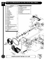
Parts List/Breakdown for the 10/12" Saw Table...
AXMINSTER
W H I T E
DIAGRAM A
36
www.axminster.co.uk
Parts List/Breakdown for the 10/12" Saw Table...
W
AXMINSTER
W H I T E
FREEPHONE 0800 371822
37
W
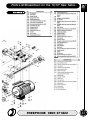
Parts List/Breakdown for the 10/12" Saw Table...
AXMINSTER
W H I T E
38
www.axminster.co.uk
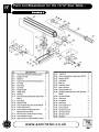
Parts List/Breakdown for the 10/12" Saw Table...
W
AXMINSTER
W H I T E
DIAGRAM B
FREEPHONE 0800 371822
39
W
Parts List/Breakdown for the 10/12" Saw Table...
AXMINSTER
W H I T E
DIAGRAM C
40
www.axminster.co.uk
Notes...
W
AXMINSTER
W H I T E
FREEPHONE 0800 371822
41
W
Parts List/Breakdown for the 10/12" Saw Table...
AXMINSTER
W H I T E
42
www.axminster.co.uk
Parts List/Breakdown for the 10/12" Saw Table...
W
AXMINSTER
W H I T E
DIAGRAM D
FREEPHONE 0800 371822
43
W
Parts List/Breakdown for the 10/12" Saw Table...
AXMINSTER
W H I T E
DIAGRAM E
44
www.axminster.co.uk
Parts List/Breakdown for the 10/12" Saw Table...
W
AXMINSTER
W H I T E
DIAGRAM F
FREEPHONE 0800 371822
45
W
Parts List/Breakdown for the 10/12" Saw Table...
AXMINSTER
W H I T E
DIAGRAM G
46
www.axminster.co.uk
Notes...
W
AXMINSTER
W H I T E
FREEPHONE 0800 371822
47
10" & 12" Sliding Table Saw
200387/600890
W
Axminster Reference No’s:
AW10BSB2 & AW12BSB2
Axminster Devon EX13 5PH UK
AXMINSTER
W H I T E
FREEPHONE 0800 371822
www.axminster.co.uk