1
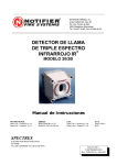
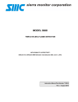
CCTV Model Flame Detector Model 20/20CTIN-CTIP User and Maintenance Manual TM 788100, Rev. A January 2005 ATEX Approved UL Approved Gost R Approved Ex II 2G EExd IIB + H2 T5 EExde IIB + H2 T5 Class I, Groups C and D 1ExdIIBT5/H2 218 Little Falls Rd., Cedar Grove, NJ 07009 USA; Phone: +1 (973) 239 8398 Fax: +1 (973) 239 7614 Web-Site: www.spectrex.net; Email: [email protected] The SharpEye Optical Flame Detector described in this document is the property of Spectrex, Inc. No part of the hardware, software or documentation may be reproduced, transmitted, transcribed, stored in a retrieval system, or translated into any language or computer language, in any form or by any means, without prior written permission of Spectrex, Inc. While great efforts have been made to assure the accuracy and clarity of this document, Spectrex, Inc. assumes no liability resulting from any omissions in this document, or from misuse of the information obtained herein. The information in this document has been carefully checked and is believed to be entirely reliable with all of the necessary information included. Spectrex Inc. reserves the right to make changes to any products described herein to improve reliability, function, or design, and reserves the right to revise this document and make changes from time to time in content hereof with no obligation to notify any persons of revisions or changes. Spectrex, Inc. does not assume any liability arising out of the application or any use of any product or circuit described herein; neither does it convey license under its patent rights or the rights of others. Warning: This manual should be carefully read by all individuals who have or will have responsibility for using, maintaining or servicing the product. The Detector is not field-repairable due to the meticulous alignment and calibration of the sensors and the respective circuits. Do not attempt to modify or repair the internal circuits or change their settings, as this will impair the system's performance and void the Spectrex, Inc. Product warranty. Spectrex Inc. - SharpEyeTM CCTV Model Flame Detector Manual – TM 788100, Rev. A January 2005 TABLE OF CONTENTS 1. Scope .................................................................................................... 1 1.1 PRODUCT OVERVIEW .....................................................................................1 1.2 DOCUMENT OVERVIEW ...................................................................................2 2. Technical Description .......................................................................... 3 2.1 PRINCIPLES OF OPERATION............................................................................3 2.1.1 Hydrocarbon fire detection....................................................................3 2.1.2 Identifying the CO2 peak .......................................................................3 2.1.3 The limitations of IR-IR flame detectors ................................................3 2.1.4 The advantages of IR3 technology .......................................................3 2.1.5 Video Picture ........................................................................................5 3. Performance ......................................................................................... 6 3.1 DETECTION SENSITIVITY .................................................................................6 3.2 FALSE ALARMS PREVENTION ..........................................................................9 4. Operation ............................................................................................ 10 4.1 VISUAL INDICATIONS ....................................................................................10 4.2 OUTPUT SIGNALS ........................................................................................11 4.2.1 Optional latching .................................................................................12 4.2.2 Built-In-Test (BIT) ...............................................................................12 4.2.3 CCTV Output ......................................................................................12 4.3 MODE SELECTION ........................................................................................13 4.3.1 Function Setup....................................................................................14 4.3.2 Sensitivity Ranges ..............................................................................14 4.3.3 Alarm Delay ........................................................................................15 4.3.4 Addresses Setup ................................................................................15 4.4 BUILT IN TEST .............................................................................................16 5.Technical Specifications..................................................................... 18 5.1 ELECTRICAL SPECIFICATIONS .......................................................................18 5.2 MECHANICAL SPECIFICATIONS ......................................................................21 5.3 ENVIRONMENTAL SPECIFICATIONS.................................................................22 6. Installation Instructions ..................................................................... 23 6.1 SCOPE ........................................................................................................23 6.2 GENERAL CONSIDERATIONS .........................................................................23 6.3 PREPARATIONS FOR INSTALLATION ................................................................24 6.4 CONDUIT INSTALLATION ................................................................................24 6.5 DETECTOR MOUNTING .................................................................................25 6.5.1 Swivel Mount Kit: ................................................................................25 6.5.2 Swivel installation (Figs. No. 8 and 9):................................................25 6.6 WIRING (REFER TO FIG. 11) .........................................................................28 6.7 TERMINAL WIRING (SEE FIG. NO.10 AND NO.11.)...........................................29 6.8 OPERATION MODE .......................................................................................32 7. Operating Instructions ...................................................................... 33 7.1 SCOPE ........................................................................................................33 7.2 POWER-UP .................................................................................................33 7.3 RESET ........................................................................................................33 I Spectrex Inc. - SharpEyeTM CCTV Model Flame Detector Manual – TM 788100, Rev. A January 2005 7.4 FUNCTIONAL TESTING ...................................................................................33 7.4.1 Manual BIT Test .................................................................................34 7.4.2 Testing with fire simulator ...................................................................34 7.5 SAFETY PRECAUTIONS .................................................................................35 8. Maintenance Instructions .................................................................. 36 8.1 SCOPE ........................................................................................................36 8.2 MAINTENANCE INSTRUMENTATION AND PERSONNEL .......................................36 8.3 PREVENTIVE MAINTENANCE PROCEDURES.....................................................36 8.4 PERIODIC MAINTENANCE PROCEDURES .........................................................36 8.4.1 Power-Up Procedure ..........................................................................36 8.4.2 Functional Test Procedure..................................................................36 8.5 MAINTENANCE RECORDS..............................................................................37 8.6 TROUBLESHOOTING .....................................................................................37 8.6.1 Fault Indication ...................................................................................37 8.6.2 False Alarm or Warning Indication ......................................................37 Appendix A - Wire Selection Tables ..................................................... 39 Appendix B – Typical Wiring Configurations....................................... 41 Appendix C – RS-485 Communication Network .................................. 45 Appendix D - Mounting the “EExde approved” version...................... 47 Appendix E - Long Range IR3 Fire Simulator ...................................... 51 II Spectrex Inc. - SharpEyeTM CCTV Model Flame Detector Manual – TM 788100, Rev. A January 2005 LIST OF FIGURES Figure 1: CCTV Model Flame Detector............................................................................. 4 Figure 2: Flame Detector Assembly - Outline Drawing .................................................... 5 Figure 3: Horizontal and Vertical Fields of View .............................................................. 8 Figure 4: Indication LEDs................................................................................................ 10 Figure 5: CCTV Screen Setup........................................................................................... 13 Figure 6: Electrical Interface ........................................................................................... 18 Figure 7: Flame Detector Assembly - Schematic Section ................................................ 20 Figure 8: IR3 Detector and Swivel Mount Assembly........................................................ 26 Figure 9: Swivel Mount Assembly - Outline Drawing...................................................... 27 Figure 10: Terminal Board............................................................................................... 30 Figure 11: IR3 Flame Detector with cover removed........................................................ 31 Figure 12: Flame Detector Wiring Diagram.................................................................... 41 Figure 13: Typical wiring diagram for 4 wire controllers ............................................... 42 Figure 14: 4-20mA wiring ................................................................................................ 43 Figure 15: RS-485 networking.......................................................................................... 45 Figure 16: Flame Detector Assembly - Wiring Diagram ................................................. 49 Figure 17: Flame Detector Assembly - Wiring Diagram (“de version”) ........................ 50 Figure 18: Fire Simulator................................................................................................. 51 Figure 19: IR3 Detector Target Point .............................................................................. 52 LIST OF TABLES Table 1: Alarm Response Time Versus Range.................................................................... 6 Table 2: Response Sensitivity Ranges................................................................................. 7 Table 3: Cone of Vision ...................................................................................................... 8 Table 4: Immunity To False Alarm Sources ....................................................................... 9 Table 5: Welding Immunity Distance ................................................................................. 9 Table 6: Output Signals Versus Detector State ................................................................ 11 Table 7: Built-in Test ........................................................................................................ 12 Table 8: Functions setting for model 20/20 CTIN and model CTIP................................ 14 Table 9: Sensitivity range ................................................................................................. 14 Table 10: Time delay ........................................................................................................ 15 Table 11: Contact Ratings ................................................................................................ 19 Table 12: Mounting according to US Version.................................................................. 25 Table 13: Mounting according to EU Version ................................................................. 25 Table 14: Maximum DC resistance at 68˚F for copper wire............................................ 39 Table 15. Wiring length in feet (meter)............................................................................. 39 III Spectrex Inc. - SharpEyeTM CCTV Model Flame Detector IV Manual – TM 788100, Rev. A January 2005 Spectrex Inc. - SharpEyeTM CCTV Model Flame Detector Manual – TM 788100, Rev. A January 2005 1. Scope 1.1 Product Overview The SharpEye CCTV Model Flame Detector (20/20CTIN and 20/20CTIP) is a selfcontained, triple-spectrum, optical flame detector that incorporates a video color camera. The detector's IR sensors and spectral band pass filters have been selected to ensure the greatest degree of spectral matching to the radiant energy emissions of fire and the lowest degree of matching to non-fire stimuli. The color video camera enables the user to investigate the monitored area, to identify the fire's source and location, and help select the best response to the situation (activation of fire suppression means). Configuration can be made to issue a live color video picture signal at all times, on request or only when a fire is detected. Therefore, the detector is also useful for standard CCTV purposes. The front side of the detector is sealed to keep the electronic and sensor chamber dry for longer life. The programmable functions are available through a RS 485 port used with a standard PC or by a Pocket PC and software supplied by Spectrex. The video signal output of the CCTV Model Flame Detector can be either NTSC or PAL. Refer to Manual TM 784050 for instructions to use the HOST software and to change the required Functions. 1 Spectrex Inc. - SharpEyeTM CCTV Model Flame Detector Manual – TM 788100, Rev. A January 2005 1.2 Document Overview This manual describes the detector and its features and provides instructions on the installation, operation and maintenance. This manual is divided into separate chapters as follows: Chapter 1. Chapter 2. Chapter 3. Chapter 4. Chapter 5. Chapter 6. Chapter 7. Chapter 8. Appendix A. Appendix B. Appendix C. Appendix D. Appendix E. Scope - a general introduction and overview of the product and the Manual, with a brief description of its content. Technical Description - the detector’s theory of operation. Performance - the detector features and capabilities. Operation - the detector’s operation modes, user interface and indications. Technical Specifications - the Detector’s electrical, mechanical and environmental specifications. Installation Instructions, including wiring and mode setting. Operating Instructions and power-up procedures. Maintenance Instructions and support procedures. Wiring Selection Tables for electrical wire selection according to installation configuration. Typical Wiring Configurations - wiring diagrams for installation. RS-485 Communication Network Mounting the “EExde approved” version Long Range IR3 Fire Simulator 2 Spectrex Inc. - SharpEyeTM CCTV Model Flame Detector Manual – TM 788100, Rev. A January 2005 2. Technical Description • • • • • • • • • • • • Detection Range: up to 200 ft (60m) for a 1ft x 1ft (0.3m x 0.3m) fire. Live color video image Ultra High Immunity to False Alarms (see section. 3.3). Advanced Digital Processing of the Dynamic Characteristics of Fire: Flickering, Threshold correlation and Ratio. Three Separate IR Channels: Between 3-5 microns. Field Programmable Sensitivity: four ranges. Two Response Levels: Warning & Detection. Solar Blind Microprocessor Based: Digital signal processing. Built In Test: Manual and Automatic (see section. 4.2.2). Electrical Interface: o Dry contact RELAYS. o Communication network RS-485. o 4-20mA output. Certification: Approved by ATEX, UL & GOST R. 2.1 Principles Of Operation 2.1.1 Hydrocarbon fire detection The triple IR flame detector detects all conceivable types of hydrocarbon fires, i.e. any fire, which emits CO2. 2.1.2 Identifying the CO2 peak The hydrocarbon fire is characterized by a typical radiation emission. The CO2 peak emits intense radiation in the spectral band between 4.2 µ - 4.5 µ and weaker radiation intensity outside this spectral band. 2.1.3 The limitations of IR-IR flame detectors CO2 in the atmosphere attenuates the radiation in this spectral band. (Absorption and emission of radiation always occur in the same band.) As a result, the greater the distance between the detector and the fire, the weaker the intensity of the radiation reaching the detector (the CO2 attenuation increases). This phenomenon explains the limitations of the existing IR-IR flame detectors in the market: • Detection distance is restricted to 33ft (10m) only. • Their immunity to false alarm sources is limited. 2.1.4 The advantages of IR3 technology To overcome these limitations, Spectrex Inc. revised an innovative concept of utilizing an additional detection channel. Three channels collect more data from the environment, permitting more accurate analysis and better performance. 3 Spectrex Inc. - SharpEyeTM CCTV Model Flame Detector Manual – TM 788100, Rev. A January 2005 After careful investigation, three channels were selected which, when operating jointly, provide optimal fire detection characteristics: Channel 1: 4.2 µ - 4.6 µ Fire - the CO2 peak Channel 2: 4.0 µ - 4.2 µ Eliminates false alarms from high temperature sources. Channel 3: 4.8 µ - 5.2 µ Eliminates false alarms from flickering of background radiation. Most IR sources, which create misleading IR alarm stimuli, including the sun, incandescent and halogen lamps, electric arc discharges, electrical heaters, etc., do not possess this unique spectral signature of fire. The IR sensors of the detector respond only to flickering of radiation signals. The signals are compared to a predetermined threshold. Processing of the results from the three IR channels is performed by the board microprocessor. The result is a much greater detection distance and a highly increased ability to distinguish between fire and false alarms. This sophisticated technology surpasses all other existing flame detection techniques on the market today. This unique flame analysis capability (patent pending) has been incorporated into the Triple-IR fire detector manufactured by Spectrex, Inc. The result is a unique flame detector, which does not produce false alarms and provides at the same time detection over greatly increased distances. Figure 1: CCTV Model Flame Detector 4 Spectrex Inc. - SharpEyeTM CCTV Model Flame Detector Manual – TM 788100, Rev. A January 2005 Figure 2: Flame Detector Assembly - Outline Drawing 2.1.5 Video Picture The color video camera enables the user to investigate the monitored area, to identify the fire source and location, to help select the best response to the situation (activation of fire suppression means). Configuration can be made to issue a live color video picture signal at all times, on request, or only when a fire is detected; therefore, the detector is also useful for standard CCTV purposes. 5 Spectrex Inc. - SharpEyeTM CCTV Model Flame Detector Manual – TM 788100, Rev. A January 2005 3. Performance 3.1 Detection Sensitivity A. Flame Detection sensitivity is the maximum distance at which the detector will reliably detect a specific size of fire & typical type of fuel (standard fire). Standard Fire: A 1ft x 1ft (0.3m x 0.3m) Gasoline pan fire with max. wind speed of 6.5 ft/sec (2 m/sec). Sensitivity Ranges: The detector has four user selectable sensitivity ranges. For each range there are two response levels. 1. WARNING (Pre-alarm) 2. ALARM The detection distance, for the WARNING level, is approximately 10% longer than the ALARM distance. Alarm response times for a “standard fire” at a specified range are shown hereunder. Table 1: Alarm Response Time Versus Range Sensitivity 1 2 3 4 Range – ft (m) 50 (15) 100 (30) 150 (45) 200 (60) Response Time (sec) 3 5 8 10 For some typical ambient conditions the Zeta parameter as defined in NFPA 72 for the detector is 0.005 (1/meter). Note: Zeta parameters may vary significantly with changes in temp, air pressure, humidity, visibility conditions, etc. 6 Spectrex Inc. - SharpEyeTM CCTV Model Flame Detector Manual – TM 788100, Rev. A January 2005 Other fuels The detector will react to other types of fires as follows: Pan Fire Size: 1ft x 1ft (0.3m x 0.3m) Maximum Wind Speed: 6.5 ft/sec (2 m/sec) Maximum Response Time: 10 sec Table 2: Response Sensitivity Ranges Type Of Fuel % Of Max. Distance at Each Sensitivity Range Gasoline 100% N-Heptane 100% Alcohol 95% 75% JP4 75% Kerosene 75% Diesel Fuel 70% Methane* 30% Propane* 30% * 0.5m plume fire B. CCTV The CCTV picture enables the user to identify a 1x1 foot gasoline flame from a distance of 100 feet (30 meters) offering a “live video” image of the monitored area. 7 Spectrex Inc. - SharpEyeTM CCTV Model Flame Detector Manual – TM 788100, Rev. A January 2005 3.2 Cone Of Vision Horizontal Vertical Table 3: Cone of Vision Flame Detector CCTV 90° 90° 90° 65° Figure 3: Horizontal and Vertical Fields of View 8 Spectrex Inc. - SharpEyeTM CCTV Model Flame Detector Manual – TM 788100, Rev. A January 2005 3.2 False Alarms Prevention The detector will not provide an alarm or a warning signal as a reaction to the radiation sources specified below. Notes: IAD = Immune at Any Distance. All sources are chopped from 0 to 20Hz. Table 4: Immunity To False Alarm Sources Radiation Source Immunity Distance ft(m) IAD IAD IAD IAD IAD IAD IAD Sunlight Indirect or reflected sunlight Vehicle headlights (low beam) conforming to MS53023-1 Vehicle IR lights (low beam) conforming to MS53024-1 Incandescent frosted glass light, 100 W Incandescent clear glass light, rough service, 100 W Fluorescent light with white enamel reflector, standard office or shop, 40 W (or two 20 W) Electric arc [12mm (15/32 in) gap at 4000 V alternating current, IAD 60 Hz] Arc welding [4 mm (5/32 in) rod; 240 A] See Table 4 Ambient light extremes (darkness to bright light with snow, water, IAD rain, desert glare and fog) Bright colored clothing, including red and safety orange. IAD Electronic flash (180 watt-seconds minimum output) IAD Movie light, 625 W quartz DWY lamp (Sylvania S.G.-55 or 6.5 (2) equivalent) Red dome light conforming to MS51073-1 IAD Blue-green dome light conforming to M251073-1 IAD Flashlight (MX 991/U) IAD Radiation heater, 1500 W IAD Radiation heater, 1000 W with fan IAD Quartz lamp (1000 W) 10 (3) Mercury vapor lamp IAD Grinding metal IAD Lit cigar 1 (0.3) Lit cigarette 1 (0.3) Match, wood, stick including flare up 10 (3) Table 5: Welding Immunity Distance SW setting Detection Range Immunity Distance 1 50 ft (15m) >13 ft (4m) 2 100 ft (30m) >20 ft (6m) 3 150 ft (45m) >30 ft (9m) 4 200 ft (60m) >40 ft (12m) 9 Spectrex Inc. - SharpEyeTM CCTV Model Flame Detector Manual – TM 788100, Rev. A January 2005 4. Operation 4.1 Visual Indications Two LED-indications are located in the detector front window: i. Power LED (Yellow) Normal - LED ON BIT failure - LED flashes (4 Hz) ii. Alarm LED (Red) Normal - LED OFF Warning - LED flashes (2 Hz) ALARM - LED ON Figure 4: Indication LEDs 10 Spectrex Inc. - SharpEyeTM CCTV Model Flame Detector Manual – TM 788100, Rev. A January 2005 4.2 Output Signals The detector controls the following outputs: • Alarm relay • Accessory relay • Fault relay • 4-20mA current output • RS-485 communication The detector can be in one of the following states. Normal: BIT: Warning: Alarm: Latched Alarm (Optional) Fault: The detector is functioning normally. The detector performs a Built-In-Test. Fire detected - changed to warning – pre-alarm state. Fire detected - changed to fire alarm state. The alarm outputs are latched due to the detection of a fire that has already been extinguished. A fault is detected during a BIT sequence or the power supply is too low. In each state the detector will activate different outputs as specified in table 6. Table 6: Output Signals Versus Detector State Power Alarm Alarm Accessory Fault Led Led Relay Relay Relay On Off Off Off On On Flash Off On On 2Hz Alarm (4) On On On On On Latch (2) On Off On Off On Fault (3) Flash Off Off Off Off 4Hz Detector State Normal Warning 4-20mA Output 5mA 10mA 15mA 5mA 0mA Note: 1. The video output can be activated continuously or only when a fire is detected, according to programmable function. See Table 8 2. The Alarm state can be latched, according to programmable function 3. The detector will be in its BIT FAULT state until it has passed a successful BIT. 4. The alarm outputs will be activated as long as the alarm conditions are present and will stop approximately 5 seconds after the fire is no longer detected. 11 Spectrex Inc. - SharpEyeTM CCTV Model Flame Detector Manual – TM 788100, Rev. A January 2005 4.2.1 Optional latching The detector includes an optional latched alarm output capability, which operates according to the programmable function. Upon the detection of a fire, the detection signal is latched until manually reset (disconnecting the power supply or performing a manual BIT). 4.2.2 Built-In-Test (BIT) Successful Manual BIT will activate the following outputs according to programmable function. Table 7: Built-in Test ALARM BIT AT YES The ALARM relay will be activated for 3 seconds. The 4-20mA output will provide 15 mA for 3 seconds. Accessory BIT AT YES The camera will be activated for 3 seconds. The 4-20mA will provide 10 mA for 3 seconds. 4.2.3 CCTV Output The video output is a standard port with two options: a. Detector model No. 20/20 CTIN is a NTSC version b. Detector model No. 20/20 CTIP is a PAL version The video output can be activated continuously or only when a fire is detected, according to programmable function. See Table 8 12 Spectrex Inc. - SharpEyeTM CCTV Model Flame Detector Manual – TM 788100, Rev. A January 2005 4.3 Mode Selection The setup screen allows viewing and programming of the detector functions. Figure 5: CCTV Screen Setup 13 Spectrex Inc. - SharpEyeTM CCTV Model Flame Detector Manual – TM 788100, Rev. A January 2005 4.3.1 Function Setup The user can select the desired mode of operation by means of host software connected etc. Table 8: Functions setting for model 20/20 CTIN and model CTIP # Name 1 ALARM LATCH YES Alarm latching enable 2 ACCESSORY RELAY (camera operation) Camera activated at warning level 3 AUTOMATIC BIT 4 ALARM BIT 5 VIDEO OUTPUT 6 EOL Automatic & manual bit (default) Successful manual bit activates the Alarm Relay for approximately 3 seconds The 4-20mA will initiate 15mA (default) Successful manual bit activates the the camera for approximately 3 seconds The 4-20mA will initiate 10mA (default) Camera always active (default) NO Alarm latching disable (default) Camera activated at detection level (together with alarm relay) (default) Manual bit only Successful manual bit does not activate the Alarm Relay Successful manual bit does not activates the camera Camera operates in accordance with other settings 4.3.2 Sensitivity Ranges The detector offers four (4) sensitivity settings. The settings refer to the gasoline 1x1foot fire, from low sensitivity of 50 ft (15m) to 200 ft (60m). For other types of fuel sensitivity, refer to table 2. 15 30 45 60 Table 9: Sensitivity range IR3 Flame Detector Sensitivity 50 ft (15 m) 100 ft (30 m) (defulat) 150 ft (45 m) 200 ft (60 m) 14 Spectrex Inc. - SharpEyeTM CCTV Model Flame Detector Manual – TM 788100, Rev. A January 2005 4.3.3 Alarm Delay The detector is equipped with an Alarm Delay option, which provides programmable time delays of 0 to 30 seconds with eight (8) fixed settings at: 0, anti-flare, 3, 5, 10, 15, 20, and 30 seconds. When an Alarm (Detection) level condition is encountered, the detector delays the execution of the Alarm output’s relay by the specified period of time. The detector will then evaluate the condition for 3 seconds. If the Alarm level is still present, the Alarm outputs will be activated. If this condition no longer exists, the detector will return to its standby state. The Alarm delay option will affect the output relay and the 4-20mA. The LEDS will indicate warning level during the delay time only if the fire condition exists. Anti Flare Anti Flare mode is selected to prevent false alarm in locations where fast flares may be present. The Time delay for fire alarm in this mode is from 2.5 to 15 seconds (mostly less than 10 seconds). Table 10: Time delay Delay (sec.) 0 A* -- anti-flare 3 5 10 15 20 30 * Default 4.3.4 Addresses Setup Refer to TM 784050 for instructions for defining the addresses of the detectors. The detector provides up to 247 addresses that can be used with RS-485 communication link. 15 Spectrex Inc. - SharpEyeTM CCTV Model Flame Detector Manual – TM 788100, Rev. A January 2005 4.4 Built In Test A. General The detectors’ Built In Test (BIT) checks the following: • Electronics circuitry • Sensors • Window cleanliness The detector can be set to perform the BIT automatically and manually or manually only. B. Principles If the result of a BIT is the same as the current status of the detector (NORMAL or BIT FAULT), the detector's status is unchanged. If the result of a BIT differs from the current status of the detector, the detectors’ status is changed (From NORMAL to BIT FAULT or from BIT FAULT to NORMAL). Note: In BIT FAULT status, the detector can continue to detect a fire. C. Manual BIT only The BIT is initiated manually by momentarily connecting Terminal No. 3 with Terminal No. 2. A successful manual BIT activates the following: • FAULT relay is closed. • ALARM relay is activated for 3 sec (only when Function Alarm BIT at YES) • 4-20 mA OUTPUT current will be 15mA only when Function Alarm BIT at YES Unsuccessful BIT activates the following: • FAULT relay is released. • 4-20 mA output indicates BIT FAULT condition (2 mA). • POWER LED (yellow) flashes (4 Hz). Note: During a MANUAL BIT, if function ‘Alarm BIT’ is in ‘YES’ position, the ALARM relay will be activated. Therefore, automatic extinguishing systems or any external devices that should not be activated during BIT should be disconnected. 16 Spectrex Inc. - SharpEyeTM CCTV Model Flame Detector Manual – TM 788100, Rev. A January 2005 D. Automatic & Manual BIT Manual Bit Functions as described in paragraph 4.4.c. In the case of an unsuccessful BIT all outputs will function as described in paragraph 4.4.c, but the BIT will be automatically executed every 1 minute. This mode of operation will continue until successful BIT has been encountered. As a result, the detector will resume its normal operation. Automatic BIT The detector automatically performs a BIT every 15 minutes. A successful BIT sequence does not activate any indication: The FAULT relay is CLOSED (NORMAL). The POWER LED is ON (NORMAL). An unsuccessful BIT sequence activates the following: The FAULT relay is opened 4-20mA output indicate BIT FAULT (2 mA) The POWER LED (yellow) flashes (4 Hz) BIT procedure will be performed every 1 minute 17 Spectrex Inc. - SharpEyeTM CCTV Model Flame Detector Manual – TM 788100, Rev. A January 2005 5.Technical Specifications 5.1 Electrical Specifications A. Operating Voltage: 18-32 VDC B. Power Consumption: Max. 150mA in Stand-by Max. 200mA in Alarm C. Electric input protection: The input circuit is protected against voltagereversed polarity, voltage transients, surges and spikes according to MILSTD-1275A. D. Electrical Interface: Figure 6: Electrical Interface 18 Spectrex Inc. - SharpEyeTM CCTV Model Flame Detector Manual – TM 788100, Rev. A January 2005 E. Electrical outputs • Dry Contact Relays: Table 11: Contact Ratings Relay Type Normal Maximum Ratings Name position Alarm SPDT N.O. N.C. 2A at 30VDC or 0.5A at 250 VAC Fault * SPST N.C. 5A at 30VDC or 250 VAC * The FAULT relay will be normally energised closed during Normal operation of the detector. The contact will open at ‘Fault’ condition or low voltage. • 4-20mA Current Output: Terminals 11 and 12: FAULT 0 + 0.5mA BIT FAULT 2mA±10% NORMAL 5mA±10% WARNING 10mA±5% ALARM 15mA±5% • Communication Network: The detector is equipped with an RS-485 communication link that can be used in installations with computerized controllers. The communicator protocol is compatible with the Modbus communicator protocol. • This protocol is a standard and widely used. • It enables continuous communication between a single standard Modbus controller (Master device) and a serial Network of up to 247 detectors. • It enables connection between different types of Spectrex detectors or other Modbus devices to the same Network. • CCTV Output The video output is a standard port with two options: • • Detector model No. 20/20 CTIN is a NTSC version Detector model No. 20/20 CTIP is a PAL version The output can be connected to standard video accessories such as a switching box. 19 Spectrex Inc. - SharpEyeTM CCTV Model Flame Detector Manual – TM 788100, Rev. A January 2005 Figure 7: Flame Detector Assembly - Schematic Section 20 Spectrex Inc. - SharpEyeTM CCTV Model Flame Detector Manual – TM 788100, Rev. A January 2005 5.2 Mechanical Specifications A. Enclosure Aluminum: Chromate coating and Epoxy enamel finish or Stainless Steel 316: Electrochemical passivated coating B. Explosion proof ATEX Ex II 2G SIRA 00ATEX 1163, 1164 Temp. -40°F (-40 °C) to 160°F (70 °C) EExd IIB + H2 T5 Option: -40°F (-40 °C) to 185°F (85 °C) Per EN 50014 & EN 50018 EExde IIB + H2 T5 Temp. -40°F (-40 °C) to 160°F (70 °C) Per EN 50014, 50018 & 50019 (see Appendix D) UL Class I, Groups C and D GOST R 1ExdIIBT5/H2 FM Class I Div. 1 Groups B, C and D; (Design to Meet) Class II Div. 1 Groups E, F and G. C. Water and dust tight NEMA 250 type 6p. IP 66 and IP 67 per EN 60529 D. Electronic Modules Conformable coating. E. Electrical connection (two positions) Standard 3/4"-14NPT conduit Optional M25 x 1.5 (ISO). F. Dimensions Base: 5.2 x 5.2 in (132 cm x 132 cm) Height: 4.7 in (120 cm) G. Weight 8.1 lbs. 14.3 lbs. (3.7 Kg) (6.5 Kg) – Aluminum Alloy – ST.ST 316 21 Spectrex Inc. - SharpEyeTM CCTV Model Flame Detector Manual – TM 788100, Rev. A January 2005 5.3 Environmental Specifications A. High Temperature Design to meet MIL-STD-810C, method 501.1 procedure II Operating temperature: +160 °F (+70 °C) Optional operating temperature: +185 °F (+85 °C) Storage temperature: +185 °F (+85 °C) B. Low Temperature Design to meet MIL-STD-810C, method 502.1, procedure I Operating temperature: -40 °F (-40 °C) Storage temperature: -65 °F (-55 °C) C. Humidity Design to meet MIL-STD-810C, method 507.1, procedure IV Relative humidity of up to 95% for the operational temperature range. D. Salt Fog Design to meet MIL-STD-810C, method 509.1, procedure I Exposure to a 5% Salt Solution Fog for 48 hours. E. Dust Design to meet MIL-STD-810C, method 510.1, procedure I Exposure to a dust concentration of 0.3 frames/cubic ft. at a velocity of 1750 fpm, for 12 hours. F. Vibration Design to meet MIL-STD-810C, method 514.2, procedure VIII Vibration at an acceleration of 1.1g within the frequency range of 5-30 Hz, and an acceleration of 3g within the frequency range of 30-500 Hz. G. Mechanical Shock Design to meet MIL-STD-810C, method 516.2, procedure I Mechanical Shock of 30g half-sin wave, for 11 msec. 22 Spectrex Inc. - SharpEyeTM CCTV Model Flame Detector Manual – TM 788100, Rev. A January 2005 6. Installation Instructions 6.1 Scope The "Spectrex" Model 20/20CTIN-CTIP is a self-contained Optical Flame Detector, designed to operate as a stand-alone unit directly connected to alarm systems or automatic fire extinguishing systems. The detector can form part of a more complex system where many detectors and other devices are integrated through a common control unit. This chapter does not attempt to cover all of the standard practices and codes of installation. Rather, it emphasizes specific points of consideration and provides some general rules for qualified personnel. Wherever applicable, special safety precautions are stressed. 6.2 General Considerations Very Important The detector should be aimed toward the center of the detection zone and have a completely unobstructed view of the protected area. Whenever possible, the detector face should be tilted down at a slight angle to prevent the accumulation of dust and dirt. Do not start an installation unless all conceivable considerations regarding detector location have been taken into account. To ensure optimal performance and an efficient installation, the following guidelines should be considered: A. Sensitivity To determine the level of sensitivity, the following issues should be considered: • Size of fire at determined distance to be detected. • Type of flammable materials. B. Spacing and Location The number of detectors and their locations in the protected area are affected by: • Size of the protected area • Sensitivity of the detectors • Obstructed lines of sight • Cone of view of the detectors C. Environment • Dust, snow or rain can reduce the detectors sensitivity and require more maintenance activities. • The presence of high intensity flickering of IR sources may affect sensitivity. 23 Spectrex Inc. - SharpEyeTM CCTV Model Flame Detector Manual – TM 788100, Rev. A January 2005 6.3 Preparations for Installation Installation should comply with NFPA 72E, as applicable to flame detectors as required. The detectors can be installed with the use of general-purpose common tools and equipment. 1 Verify the appropriate Purchase Order. Record the Part No. and the Serial No. of the detectors and the installation date in an appropriate Log-book. 2 Open the container package prior to detector installation and visually inspect the detector. 3 Verify that all components required for the detector installation are readily available before commencing the installation. In case that the installation is not completed in a single session, secure and seal detectors and conduits. 4 For wiring, use color-coded conductors or suitable wire markings or labels. 12 to 20 AWG wires may be used for site wiring. The selection of wire gauge should be based on the number of detectors used on the same line and the distance from the control unit, in compliance with specifications (See Appendix A). 6.4 Conduit Installation 1 To avoid water condensation water in the detector, it should be installed with the conduits placed downward, and should include drain holes. 2 When using the optional swivel mount, use flexible conduits for the last portion connecting to the detector. 3 For installations in atmospheres as defined in Group B of the NFPA 72E, conduits inlets should be sealed. 4 When pulling the cables through the conduits, ensure that they are not tangled or stressed. Extend the cables about 12 in. (30 cm.) beyond the detector location to accommodate wiring after installation. 5 After the conductor cables have been pulled through the conduits, perform a continuity test. 24 Spectrex Inc. - SharpEyeTM CCTV Model Flame Detector Manual – TM 788100, Rev. A January 2005 6.5 Detector Mounting The detector may be mounted on a simple fabricated bracket, or preferably the optional Swivel Mount, Model 20/20-003. The Swivel Mount enables the detector to be rotated up to 40 degrees in all directions. 6.5.1 Swivel Mount Kit: Table 12: Mounting according to US Version Item Qty. Type/Model Location Swivel Mount 1 20/20-003 1/4"-20UNC Screw 4 1/4" –20UNC Detector - Holding plate 1/4" Spring Washer 4 1/4" Detector - Holding plate Table 13: Mounting according to EU Version Item Qty. Type/Model Location Swivel Mount 1 20/20-003-1 Screw 4 M6 X 1P Detector - Holding plate Spring Washer 4 M6 Detector - Holding plate 6.5.2 Swivel installation (Figs. No. 8 and 9): 1 Place the swivel mount (item 6) in its designated location and secure it with four (4) M6 or 1/4" screws (item 11) (recommended), placed 3.0 in. (76.2 mm.) apart on the swivel mount plate (item 10). Note: Skip this step if the Swivel Mount is already installed. Also detector removal for maintenance purpose does not require Swivel Mount removal. 2 Unpack the detector. 3 Place the detector, with its conduit inlets / electrical entries pointing down, on the holding plate of the swivel mount (item 7). Secure the detector by four (4) 1/4"-20UNC (or M6) screws with 1/4" (or M6) spring washers from the Swivel Mount Kit (using the holes (item 5)). Use 3/16 Hex Key for 1/4" screws and No. 5 for M6 screws. 4 Tighten the three locking 3/8"-24UNF screws (item 8) of the swivel mount ring until the friction in the ball joint holds the detector in its position, maintaining the ability to be moved by hand-applied force (Use 3/16" HEX KEY). 5 Point the detector towards the protected area and make certain that the view of the area. Secure the detector in that position by tightening the locking screws (item 8) of the swivel mount ring. The detector is now correctly located and aligned and ready for connecting to the system. 25 Spectrex Inc. - SharpEyeTM CCTV Model Flame Detector Manual – TM 788100, Rev. A January 2005 Figure 8: IR3 Detector and Swivel Mount Assembly 26 Spectrex Inc. - SharpEyeTM CCTV Model Flame Detector Manual – TM 788100, Rev. A January 2005 Description 1 Protective Set Screws 2 Ground Terminal (for ATEX) or Ground Thread (for FM) 3 Back Cover 4 Housing 5 Swivel Mount Screw Hole 6 Swivel Mount 7 Holding Plate 8 Locking Screws 9 Detector Mounting Screws 10 Swivel Mount Plate 11 Swivel mounting screws Figure 9: Swivel Mount Assembly - Outline Drawing 27 Spectrex Inc. - SharpEyeTM CCTV Model Flame Detector Manual – TM 788100, Rev. A January 2005 6.6 Wiring (Refer to Fig. 11) 1 Disconnect power. 2 Remove the four (4) protective set-screws from detector front. (Fig. 8 Item 1) 3 Release the four (4) socket-head screws that secure the detector housing (Item 1) to its back cover (Item 4) Using HEX KEY No. 5. Hold the housing (Item 1) during the removal of the screws. With the screws removed, pull the detector housing (Item 1) from its cover (Item 4). The Terminal Board inside the detector cover is now revealed. 4 Remove the protective plug mounted on the detector conduit inlet / electrical entry, pull the wires through the detector cover (Item 4) and secure them firmly to the cover using the cable-clamp (Item 2) attached to it. Use a 3/4"-14NPT or M25x1.5 explosion-proof conduit /cable gland connection to assemble the conduit / cable to the detector. 5 Connect the wires to the required terminals (Item 3) according to the wiring diagram. See paragraph 6.7. 6 Connect the grounding wire to the ground screw outside the detector cover (Fig. 8 item 2). The detector must be well grounded to Earth Ground for proper operation. 7 Verify the wiring. Improper wiring may damage the detector. 8 Check the wires for secure mechanical connection and press them neatly against the terminal board to prevent them from interfering while closing the detectors’ housing. 28 Spectrex Inc. - SharpEyeTM CCTV Model Flame Detector Manual – TM 788100, Rev. A January 2005 6.7 Terminal wiring (See Fig. No.10 and No.11.) The detector contains a Terminal Board consisting of two (2) terminal blocks (Item 4). The left terminal block is labeled 1 to 7, the right terminal block is labeled 8 to 14. The following describes the function of each electrical terminal of the detector: • Power Supply (Terminal Numbers 1, 2): Input power - Terminal No. 1. The RETURN - Terminal No. 2. • Manual Bit Activation (Terminal No. 3): Terminal No. 3 is used for Manual BIT activation. Manual BIT is initiated by a momentary connection of Terminal No. 3 to the power supply Return line. • Fault Relay (Terminal Numbers 4, 5): The Fault output is N.O. SPST relay at Terminals No. 4 and 5. The contacts are energised closed when the detector is in its normal operational condition. • Alarm Relay (Terminal Numbers 6, 7, 8): The Alarm output is a change over contact relay (SPDT). Terminal No. 6 - N.O. relay contact. Terminal No. 7 - COMMON relay contact. Terminal No. 8 - N.C. relay contact. • CCTV (Terminal Numbers 9, 10): The CCTV output is a standard video output available at PAL or NTSC according to Model No.20/20 CTSN for NTSC and 20/20CTIP for PAL. Terminal No. 9 - video signal (-) Terminal No. 10 - video signal (+) Note To protect the dry contacts from voltage surges when connected to reactive loads (electric motors, sirens, etc.), connect an appropriate varistor over these contacts. 29 Spectrex Inc. - SharpEyeTM CCTV Model Flame Detector Manual – TM 788100, Rev. A January 2005 • 4-20mA Output (Terminal Numbers 11, 12): Terminal Numbers 11 and 12 are used for analog, 4-20mA current output as specified in paragraph 4.e Terminal No. 11 - output Terminal. Terminal No. 12 - input Terminal (see appendix B for more details) • RS-485 (Terminal Numbers 13, 14): Terminal Numbers 13 and 14 are used for communication network as specified in appendix C. Terminal No. 13 - positive (+) lead. Terminal No. 14 - negative (-) lead. Figure 10: Terminal Board 30 Spectrex Inc. - SharpEyeTM CCTV Model Flame Detector Manual – TM 788100, Rev. A January 2005 Description 1 Housing 2 Securing Cable 3 Terminal Board 4 Back Cover 5 Inlet Conduit 6 Earth Terminal Figure 11: IR3 Flame Detector with cover removed 31 Spectrex Inc. - SharpEyeTM CCTV Model Flame Detector Manual – TM 788100, Rev. A January 2005 6.8 Operation Mode When wiring is completed the operational mode can be selected. Mode selection is achieved through RS-485 using a PC with Spectrex Host software. Refer to TM784050. Programmable Function: Modes of operation are programmable with a PC or Handheld unit according to the selection table in Paragraph 4.3.1 and Refer to TM 784050. Refer to here in 4.3.1 etc. Address: The detector has the capability of acting as an addressable device. The detector provides 247 addresses, which can be used by the RS-485 communications link as described in paragraph 4.3.4 and Refer to TM 784050. Alarm Delay: An Alarm Delay may be required for certain applications. The detector has an Alarm Delay that permits time delays from 0, anti-flare, 3, 5, 10, 15, 20 and 30 seconds respectively. The delay can be defined by the RS-485. See paragraph 4.3.3 and refer to TM 784050. 32 Spectrex Inc. - SharpEyeTM CCTV Model Flame Detector Manual – TM 788100, Rev. A January 2005 7. Operating Instructions 7.1 Scope The following instructions are designed to obtain optimal performance from the detector over its life cycle. 7.2 Power-Up 1 Apply power and wait approximately 60 seconds for the automatic self-test of the detector. Note: Applying power initiates the following sequence: • POWER LED flashes • BIT is executed, if successful then: o POWER LED turns ON continuous o FAULT relay contacts close 2 Wiring Inspection: If a short-circuit or line discontinuity exists, indications will appear on the control unit display panel. Review your wiring. 3 The detector goes into its FAULT state when supply voltage drops under 16.5V. The detector status goes back to NORMAL, when the supply voltage is above 17.5V. 4 Detector Inspection: Visually inspects the viewing window of the detector. It should be clean and clear. The POWER LED should be ON and the ALARM LED should be OFF. The ALARM should be OFF and the FAULT relay should be ON. The 4-20mA Output should be 5mA. 5 If any of the outputs or indications is different from the description in step 4, see paragraph 8.6.1 for troubleshooting. The Flame Detector is now ready for Functional Testing. 7.3 Reset If the optional alarm latching mode has been selected, RESET of a detector, when in its ALARM state, can be activated by disconnecting power (terminal No. 1 or terminal No. 2), or initiating a manual BIT. 7.4 Functional testing Following is a test procedure for proper functioning of the detector. The detector can be tested using the Manual Built-in-Test (BIT) or the Spectrex IR3 Fire Simulator - 20/20-310 33 Spectrex Inc. - SharpEyeTM CCTV Model Flame Detector Manual – TM 788100, Rev. A January 2005 7.4.1 Manual BIT Test Important Note! If the function setup “Alarm BIT” is in YES, then the Alarm and 4-20mA Output will be activated during a manual BIT, therefore, automatic extinguishing systems or any external devices that may be activated during BIT must be disconnected. 1 Verify that the detector is operating properly. 2 Initiate manual BIT. After a few seconds the following occurs: • Alarm Relay will be activated and the 4-20mA output turns to 15mA for 3 seconds (only if “Alarm BIT” at YES). • The CCTV will be activated and the 4-20mA output turns to 10mA for 3 seconds (only if “Accessory BIT” at YES). • The 2 LEDs should be ON. • Fault Relay will stay active during the test. 7.4.2 Testing with fire simulator This test simulates an exposure of the detector to a real fire condition. The detector is exposed to the radiation in the specified detection level. As a result the detector must generate a Fire Alarm signal. Important Note! If the detector is exposed to a fire simulator, the Alarm Relay and 4-20mA will be activated during the simulation. Therefore, automatic extinguishing systems or any external devices, which may be activated during this process, must be disconnected. 1 Apply power to the system and wait up to 60 seconds for turning of the detector to normal state. Power led turns on. If the detector is on, skip this step. 2 Aim the Spectrex Fire Simulator Model 20/20-310 at the target point of the detector (see Fig. 22), in a way that the radiation emitted by it is facing directly towards the detector. (See appendix E) 3 Press the operation button once. After a few seconds the Alarm LED should be ON for a few seconds. The 4-20mA output should turn to 15mA for a few seconds and then return to 5mA. The Alarm Relay should also turn on during this period. The CCTV will operate in parallel to the Alarm Relay if “Accessory BIT” at YES. This completes the installation procedure. The detector and system are now ready for operation. 34 Spectrex Inc. - SharpEyeTM CCTV Model Flame Detector Manual – TM 788100, Rev. A January 2005 7.5 Safety Precautions After Powering-up, the detector requires hardly any attention in order to function properly, but the following should be noted: 1 Follow the instructions in the manual and refer to the drawings and specifications issued by the manufacturer. 2 Do not expose the detector to radiation of any kind unless required for testing purposes. 3 Do not open the detector housing, while power is supplied. 4 Do not touch internal parts. Interference with internal circuits may impair detector performance and will invalidate manufacturer's Warranty. 5 Disconnect external devices, such as automatic extinguishing systems before carrying out any maintenance. 35 Spectrex Inc. - SharpEyeTM CCTV Model Flame Detector Manual – TM 788100, Rev. A January 2005 8. Maintenance Instructions 8.1 Scope This chapter deals with preventive maintenance, describes possible faults in detector operation and indicates corrective measures. Ignoring these instructions may cause problems with the detector and may invalidate the warranty. Whenever a unit requires service, please contact the manufacturer or its authorized distributor for assistance. 8.2 Maintenance Instrumentation and Personnel The detectors’ maintenance requires ordinary tools and qualified personnel, who should be familiar with local codes and practices. 8.3 Preventive Maintenance Procedures The detector must be kept as clean as possible. The viewing window and the reflector of the 20/20CTIP and 20/20CTIN Flame Detector Models must be cleaned on a periodic basis. The frequency of cleaning operations depends upon the environmental conditions and specific applications. The fire detection system designer will give his recommendations. Use of the optional AIR SHIELD Model 20/20-920 is highly recommended and will help to keep the window clean and prevent dirt from accumulating on the window. 1 Disconnect power to the detector before proceeding with any maintenance including lens cleaning. 2 To clean the detector viewing window and reflector use water and detergent, rinse with clean water. 3 Where dust, dirt or moisture accumulates on the window, first clean with a soft optical cloth and detergent, then rinse with clean water. 8.4 Periodic Maintenance Procedures In addition to preventive cleaning and maintenance, the detector should be functionally tested every six months. This test should also be carried out for any reason the detector has been opened. 8.4.1 Power-Up Procedure Perform Power-Up procedure every time power is restored to the system. Follow the instructions in paragraph 7.2. 8.4.2 Functional Test Procedure Perform a functional test of the detector as described in paragraph 7.4. 36 Spectrex Inc. - SharpEyeTM CCTV Model Flame Detector Manual – TM 788100, Rev. A January 2005 8.5 Maintenance Records It is recommended to record maintenance operations performed on a detector in a system Log-book. The record should include information, which identifies the unit, the installation date, contractor, and entries for every maintenance operation performed including the description of the operation, date and personnel ID. If a unit is sent to the manufacturer or distributor for service, a copy of the Maintenance records should accompany it. 8.6 Troubleshooting 8.6.1 Fault Indication 1 Check power supply for correct voltage, polarity and wiring. 2 Check detector window and reflector for cleanness. If necessary clean the window as indicated in paragraph 8.3 and repeat the test. 3 Disconnect the power supply to the system and check the detector's internal wiring. 4 Reconnect power supply and wait approximately 60 seconds. Repeat the test. If the indication LED is still flashing, the unit requires service. 8.6.2 False Alarm or Warning Indication 1 Disconnect the power supply from the system and check internal wiring. 2 Reconnect power supply and wait approximately 60 seconds. If indication remains, the unit requires service. 37 Spectrex Inc. - SharpEyeTM CCTV Model Flame Detector 38 Manual – TM 788100, Rev. A January 2005 Spectrex Inc. - SharpEyeTM CCTV Model Flame Detector Manual – TM 788100, Rev. A January 2005 Appendix A - Wire Selection Tables General Instructions For Electrical Wiring 1. Refer to Table 14 to determine the required wire gauge for general wiring, such as relay wiring. Calculate the permitted voltage fall with respect to loads current, wire gauge and length of wires. 2. Refer to Table 15 to select wire gauge for power supply wires. DO NOT connect any circuit or load to detectors’ supply inputs. Table 14: Maximum DC resistance at 68˚F for copper wire AWG # mm2 Ohm per 100 ft. Ohm/100 meter 26 0.12 - 0.15 4.32 14.15 24 0.16 - 0.24 3.42 11.22 22 0.30 - 0.38 1.71 5.60 20 0.51 - 0.61 1.07 3.50 18 0.81 - 0.96 0.67 2.20 16 1.22 - 1.43 0.43 1.40 14 1.94 - 2.28 0.27 0.88 12 3.09 - 3.40 0.17 0.55 10 4.56 - 6.64 0.11 0.35 A. Select "Number of detectors" connected in one circuit. B. Select "wiring length" per your installation requirements. C. Refer to "power supply range" for voltage extreme applied. No. of Detectors 24 Table 15. Wiring length in feet (meter) Recommended Wire Diameter (AWG) 18 16 14 - 20 18 16 14 - - 22-32 16 20 18 16 14 - 22-32 12 20 18 16 14 - 20-32 8 20 18 16 14 - 20-32 4 and less 20 18 16 16 14 20-32 Feet (meter) 164 328 492 656 820 (50) (100) (150) (200) (250) Max. Length from Power Supply to Last Detector 39 Power Supply Range (VDC) 22-32 Spectrex Inc. - SharpEyeTM CCTV Model Flame Detector Manual – TM 788100, Rev. A January 2005 CCTV Wire Type The wire for the video picture must be Twisted Pair Wire. Network Wiring Wire Gauge Category Type Impedance DC Loop Resistance Differential Capacitance UTP 24 AWG or thicker 2, 3, 4, 5 or better 100±20 ohms 52 ohms per 1,000ft/300m 19pF/ft max 40 Spectrex Inc. - SharpEyeTM CCTV Model Flame Detector Manual – TM 788100, Rev. A January 2005 Appendix B – Typical Wiring Configurations Figure 12: Flame Detector Wiring Diagram 41 Spectrex Inc. - SharpEyeTM CCTV Model Flame Detector Manual – TM 788100, Rev. A January 2005 Figure 13: Typical wiring diagram for 4 wire controllers Notes: For EOL Resistors Values See Controller Manual 42 Spectrex Inc. - SharpEyeTM CCTV Model Flame Detector Manual – TM 788100, Rev. A January 2005 Figure 14: 4-20mA wiring Notes: The detectors are factory set to isolated 4-20mA ‘sink’ version. To work at non-isolated 4-20mA version (source), connect Terminal 12 to Terminal 1. The 4-20mA meter is connected between Terminal 11 and Terminal 2. 43 Spectrex Inc. - SharpEyeTM CCTV Model Flame Detector Manual – TM 788100, Rev. A January 2005 CCTV Wire Type The wire for the video picture must be Twisted Pair Wire. Network Wiring Wire Gauge Category Type Impedance DC Loop Resistance Differential Capacitance UTP 24 AWG or thicker 2, 3, 4, 5 or better 100±200 ohms 52 ohms per 1,000ft (300m) 19pF/ft max The Twist Pair must be connected to a PASSIVE or ACTIVE receiver depending on the length cable from the CCTV to the receiver. 0 - 1000 ft (300m) 660 - 3300 ft (200m - 1000m) Require PASSIVE receiver Require ACTIVE receiver The connection from the receiver should be made by coax cable connected to the monitor or through a switching box when connecting two (2) or more CCTVs to the same monitor. 44 Spectrex Inc. - SharpEyeTM CCTV Model Flame Detector Manual – TM 788100, Rev. A January 2005 Appendix C – RS-485 Communication Network Using the RS-485 network capability of the IR3 detector and additional software it is possible to connect up to 32 detectors in an addressable system with 4 wires only (2 for power & 2 for communication). Using repeaters, the number of detectors can be much larger (32 detectors for each repeater) up to 247 on the same 4 wires. When using the RS-485 network it is possible to read each detector status (FAULT, WARNING, ALARM) and to initiate a BIT to each detector individually. Fore more details, consult the factory. Figure 15: RS-485 networking 45 Spectrex Inc. - SharpEyeTM CCTV Model Flame Detector 46 Manual – TM 788100, Rev. A January 2005 Spectrex Inc. - SharpEyeTM CCTV Model Flame Detector Manual – TM 788100, Rev. A January 2005 Appendix D - Mounting the “EExde approved” version The EExde approved version provides an additional EExe terminal box attached below the EExd detector and therefore allows easier access for wiring in difficult environments and hazardous areas (see fig. 18). The unit is prewired to the terminals in the additional EExe terminal section ready for field wiring connections 1. Detector Mounting The detector may be mounted on a simple fabricated bracket, or preferably the optional Swivel Mount, Model 20/20-003. The Swivel Mount enables the detector to be rotated up to 40 degrees in all directions. 1.1 Swivel Mount Kit - Use the kit from the paragraph 6.5.1 1.2 Swivel installation 1 Refer to Fig.8 and Fig 9. Place the swivel mount (item 6) in its designated location and secure it with four (4) M6 or 1/4" screws (item 11) (recommended), placed 3.0 in. (76.2 mm.) apart on the swivel mount plate (item 10). Note: Skip this step if the Swivel Mount is already installed. Also detector removal for maintenance purpose does not require Swivel Mount removal. 2 Unpack the detector. 3 Place the detector, with its conduit inlets / electrical entries pointing down, on the holding plate of the swivel mount (Fig. 8 item 7). Secure the detector by four (4) M6 screws with M6 spring washers from the Swivel Mount Kit using the holes (Fig. 9 item 5). You can use the thread on the modified cover (Fig. 18 item 1) marked either triangle symbol (∆) or square symbol ()ٱ. Use No. 5 Hex Key for M6 screws. 4 Tighten the three locking 3/8"-24UNF screws (Fig. 9 item 8) of the swivel mount ring until the friction in the ball joint holds the detector in its position. Yet, still permits it to be moved by hand-applied force (Use 3/16" HEX KEY). 5 Point the detector towards the protected area and make certain that the view of the area. Secure the detector in that position by tightening the locking screws (Fig.9 item 8) of the swivel mount ring. The detector is now correctly located and aligned and ready for connecting to the system. 47 Spectrex Inc. - SharpEyeTM CCTV Model Flame Detector Manual – TM 788100, Rev. A January 2005 2. WIRING (REFER TO FIG. 18.) 1 Disconnect power. 2 Release the four (4) slotted-head screws (item 3) that secure the chamber cover (Item 2). The chamber is now revealed. 3 Remove the protective plug mounted on the detector conduit inlet/ electrical entry, pull the wires through the detector chamber (Item 7). Use a 3/4"14NPT or M25x1.5 explosion-proof conduit / cable gland connection to assemble the conduit / cable to the detector. 4 Connect the wires to the required terminals (Item 4) according to the wiring diagram. See paragraph 2.1 and figures no. 19 and no. 20. 5 Connect the grounding wire to the ground screw outside the detector cover (Item 5). The detector must be well grounded to Earth Ground for proper operation. 6 Verify the wiring. Improper wiring may damage the detector. 7 Check the wires for secure mechanical connection and press them neatly against the terminal to prevent them from interfering while closing the cover (Item 2). 8 Place and secure the cover chamber (Item 2) using four (4) slotted-head screws (Item 3). 48 Spectrex Inc. - SharpEyeTM CCTV Model Flame Detector Manual – TM 788100, Rev. A January 2005 Figure 16: Flame Detector Assembly - Wiring Diagram Description 1. Modified Back Cover 5. Ground Terminal 2. EExe Chamber Cover 6. Mounting Thread 3. Slotted Screw 7. EExe Chamber 4. Terminal Block 8. Conduit Inlet 49 Spectrex Inc. - SharpEyeTM CCTV Model Flame Detector Manual – TM 788100, Rev. A January 2005 2.1 Terminal Wiring The terminal block is labeled 1 to 6. (See Fig. No.18) The following describes the function of each electrical terminal of the detector: Power Supply (Terminal Numbers 1, 2): Input power - Terminal No. 1. RETURN - Terminal No. 2. CCTV (Terminal Numbers 3, 4): The CCTV output is a standard video output available at PAL or NTSC according to Model No. 20/20 CTSN for NTSC and 20/20 CTIP for PAL. Terminal No. 3 - video signal (-) Terminal No. 4 - video signal (+) 4-20 mA Output (Terminal Numbers 5, 6): Terminal Numbers 5 and 6 are used for analog, 4-20mA current output as specified in paragraph 5.e Terminal No. 5 - output Terminal. Terminal No. 6 - input Terminal (see appendix B for more details) Note • For other ANALOG OUTPUTS consult the factory. • The detector contains an EExe chamber consisting of a terminal block (Item 4). Figure 17: Flame Detector Assembly - Wiring Diagram (“de version”) 50 Spectrex Inc. - SharpEyeTM CCTV Model Flame Detector Manual – TM 788100, Rev. A January 2005 Appendix E - Long Range IR3 Fire Simulator Figure 18: Fire Simulator Product Description The SharpEye IR3 Long Range Fire simulator 20/20-310 is designed specifically for use with the IR3 flame detectors. The Fire Simulator emits IR radiation in a unique sequential pattern corresponding and recognizable by the IR3 detector as fire. This allows the IR3 detectors to be tested under real fire conditions without the associated risks of an open flame. There is a specially designed beam collimator model number 20/20-190 used for extended range. Unpacking In addition to the delivery form, there should be the following contents: • • • • Fire Simulator with built in batteries Battery charger Optional Beam Collimator Storage Case Operating Instructions WARNING: Do not open the Fire Simulator to charge the batteries or for any other reason in a hazardous area. CAUTION: The following test will simulate a real fire condition and may activate the extinguishing system or other alarms. If this is not desired, disconnect them before the test and reconnect after the simulation. 51 Spectrex Inc. - SharpEyeTM CCTV Model Flame Detector Manual – TM 788100, Rev. A January 2005 Figure 19: IR3 Detector Target Point Follow these instructions to simulate a fire: 1. Aim the Fire Simulator towards the detector’s “Target Point”. 2. For testing keep a distance of at least 20 inches (50cm) from the detector. 3. Press the operation button once. Fire simulation will last for 20 seconds. The detector will send an alarm signal (solid red LED). 4. For another fire simulation a 20 second time lapse is required between tests. 5. Make sure the optical window is clean and keep the Fire Simulator in a safe place when not in use. Battery Charging The Fire Simulator uses NiCad batteries as a rechargeable power source. When the batteries are fully charged it will operate for at least 60 uses without recharging. An internal buzzer is sounded when the voltage from the batteries is lower than the required operational level. 1. Place the Fire Simulator on a table in a safe area. 2. Turn the sealed plug (next to the operation button) counter-clockwise with a suitable wrench. 3. Connect the battery charger. 4. Charge for a maximum of 14 hours. 5. Disconnect the charger. 6. Tighten the sealed plug clockwise. 52 Spectrex Inc. - SharpEyeTM CCTV Model Flame Detector Manual – TM 788100, Rev. A January 2005 Specifications Mechanical Explosion Proof Enclosure: NFPA (designed to meet) Class I, Division 1 & 2 Groups B, C and D Class II, Division 1 & 2 Groups E, F, and G ATEX EX II2G, NEMKO 02ATEX255 EExd IIB T5 50˚C per En 50-014 & EN50-018 Electrical Power: 8 VDC Max. 6 x Rechargeable 1.2 VDC NiCad Batteries Current: 2.5A Avg. Charge: 400mA for 14 Hours Environmental Temperature Range: Vibration Protection: Water and Dust: -4º F (-20º C) to 122º F (50º C) 1g (10-50hz) IP 67 per EN 60529 Physical Dimension: Weight: 11.5 x 10.1 x 3.9 in (292 x 258 x 100 mm) 7.5 lb. (3.4 Kg) Range* Sensitivity Range Standard 1 (Low) 2 3 4 (High) 50 ft (15 m) 100 ft (30 m) 150 ft (45 m) 200 ft (60 m) 3.8 ft 7 ft 10 ft 14.5 ft (1.2 m) (2.2 m) (3.2 m) (4.5 m) Extended Range (with Collimator) 7 ft (2.2 m) 14.5 ft (4.5 m) 22 ft (7.0 m) 29 ft (9.0 m) * The minimum distance from the detector is 20 inches (50cm) * At extreme temperatures - 15% Max. Reduction in range 53 Spectrex Inc. - SharpEyeTM CCTV Model Flame Detector Manual – TM 788100, Rev. A January 2005 Technical Support For all technical assistance or support, contact: 218 Little Falls Road Cedar Grove, NJ 07009, USA Tel: +1 (973) 239 8398 Fax: +1 (973) 239 7614 Email: [email protected] Web-site: www.spectrex.net Your Local Office: SPECTREX INC. Texas (USA) Mr. Jay Cooley, Regional Sales Manager 16203 Park Row, Suite 150 Houston, Texas 77084 USA Phone: +1 (832) 321 5229 Email: [email protected] Europe Mr. Ian Buchanan, Regional Manager 6 Applecross Road Glasgow G66 3TJ United Kingdom Phone: +44 (0) 141 578 0693 Email: [email protected] Far East Mr. Deryk Walker, Regional Sales Manager 59 Fen Ji Hu, Danshui Taipei County 25163 Taiwan (ROC) Phone: +886 2 8626 2893 Mobile: +886 926 664 232 Email: [email protected] 54