1
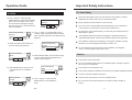
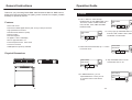
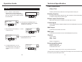
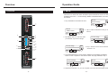
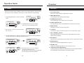
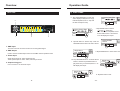
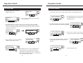
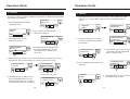
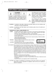
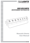
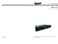
User Instructions
RMD-1220
Rack Mount Dimmer-12Channel
24-004-2355-00
Rev1.0
It is important to read this instruction book prior to installing or using your new
product for the first time.
Contents
Contents
Operation Guide
7) SETUP
Important Safety Introductions.................................................1
For Your Safety
Caution
General Introduction...................................................................2
22. Secondly tap ENTER button to release
all parameter to default or use ESC
button exit without record.
Factory Default
Confirm
ESC
MENU
ENTER
Features
Physical Dimensions
Technical Specifications............................................................3
Power Requirements
Dimming Capacity
Dimmer Output Connections
Control Inputs
Dmx Output
DMX Input
Physical
Environment(Oprating)
Overview.....................................................................................4
Front View.............................................................................................................4
Rear View..............................................................................................................6
Main Power & Output Termination........................................................................7
Operation Guide.........................................................................8
Menus....................................................................................................................8
1) Home(Live display)............................................................................................8
2) Local Control......................................................................................................9
3) Address............................................................................................................10
4) Scenes REC.....................................................................................................12
5) Play Scene.......................................................................................................14
6) Curves..............................................................................................................16
7) Setup................................................................................................................17
8) Information........................................................................................................21
8) INFORMATION
This menu is used to view the software version and the internal dimmer pack
temperature.
1. Use UP/DOWN button to select and tap
ENTER button to enter INFORMATION
menu. You can use >> button to scroll
Software Version and Temperature.
MENU
SOFTWARE
Ver00.01 Jun07
ESC
ENTER
Information
Software Version
ESC
ESC
MENU
ENTER
2. Tap ENTER button to select Software
Version, the LCD will show you the
version number and date. Tap ESC or
ENTER button will back to the previous
menu.
3. Tap >> button to select Temperature and
use ENTER button to enter in. Two
temperature are displayed, one for the
left heat sink(dimmer1~6) and the other
for the right heat sink(dimmer 7~12).
Tap ESC or ENTER button will return to
previous menu.
Information
Temperature
MENU
MENU
TEMPERATURE
L=+029 R=+029
ESC
ENTER
4. Tap ESC button to exit and back to
HOME page.
ENTER
-21-
Operation Guide
Important Safety Instructions
For Your Safety
7) SETUP
16. Use >> button to select and tap
ENTER button to enter FAN COOLING
menu. This menu allow you to control
how the internal cooling fans operate.
The menu gives you a choice of Normal,
Full On and Silent.
FAN COOL[Normal]
Normal
ESC
MENU
ENTER
Never open this product under any circumstances. Any repairs or internal
adjustments should be made only by a trained technician.
FAN COOL[Normal]
Normal
ESC
Never operate this product with the cover removed.
Do not use your unit immediately after transporting it from a cold place to
a warm place, as condensation cause the unit to malfunction.
ENTER
17. Use >> button to scroll Normal, Full On
or Silent. When selected Normal, the dimmer
pack will keep temperature not higher than 70
degree C.
FAN COOL[Full On]
Full On
18. When selected Full On,all the time
the Fans keep in full speed on.
ESC
MENU
To prevent fire or shock hazard,keep your unit away from humid areas and
abnormally hot places.
The apparatus shall not be exposed to dripping or splashing and that no
objects filled with liquids, such as vases, shall be placed on the apparatus.
The ventilation should not be impeded by covering the ventilation opening
with items, such as newspaper, table-cloths, curtains, etc.
Do not install near any heat sources such as radiators, heat registers,
stoves, or other apparatus that produce heat.
ENTER
MENU
FAN COOL[Silent]
Silent
ESC
MENU
19. When selected Silent, The Fans are running
in lower speed and the temperature not
higher than 90 degree C.
ENTER
Caution
This product must be grounded.
No user serviceable parts inside, do not attempt repairs. Should you product
fail, contact your local dealer.
FAN COOL[Silent]
Silent
20. Tap ENTER button to save your set
or use ESC button to exit without
record.
ESC
MENU
ENTER
Improvement and changes to
All
Rights
Reserved!
This
product
is notand
forthis
domestic use .
specifications,
design
manual, may be made at any time
All
Rights
This
productReserved!
should be installed and serviced only by suitable qualified personnel.
without prior notice.
Provide occasional ventilation during use.
ESC
Disconnect the power when not use for extended period.
MENU
Factory Default
Confirm
ENTER
21. Use >> button to select and tap
ENTER button to enter DEFAULT
menu.
-20-
Do not use the unit in places subject to excessive humidity, vibration or
bumps.
-1-
Operation Guide
General Instructions
Thanks for you purchasing Botex RMD-1220 Rack Mount Dimmer. RMD-1220 is
designed to build and expand your lighting control console.It is compact, portable
and easy to operate by menus.
Features
-19"/2U rack mount
-12 channel modular digital dimmer pack,12 ways x 20A per channel
- High speed Micro Processor
- Standard USITT DMX-512 (1990)
- Dual fan cooling
- Dual SCR thyristor
- 16 digital in 2 lines LCD display
- 20A UL approved MCB x 12
- Power Requirement:AC 120V~60Hz
- Connector: Terminal
- ArtNET(Ethernet protocol) available
7) SETUP
12. Use >> button to select and tap
ENTER button to enter DMX Failed menu.
This menu contains ArtNET Failed Off,
Hold, Off After 10min, DMX fail ArtNET
and GoScene##.
DMX Failed
Off
ESC
MENU
MENU
DMX Failed
Off
ESC
ENTER
13. In this page, tap UP/DOWN button to
scroll Off, Hold, Off After 10min, DMX
Fail ArtNET or GoScene##.
ENTER
14. When selected GoScene##, tap >> button
to activate cursor.
DMX Failed
GoScene01
ESC
MENU
ENTER
Physical Dimensions
DMX Failed
GoScene02
ESC
MENU
15. Tap UP/DOWN button to scroll
GoScene## from 01~99
ENTER
-2-
MENU
DMX Failed
GoScene02
16. In DMXFailed menu, you can
tap ENTER button to save your set
or use ESC button to exit without
record.
ESC
-19-
ENTER
Operation Guide
Technical Specification
Power Requirements
7) SETUP
Voltage: 120V AC
Frequency: 60Hz
7. Use >> button to select and tap
ENTER button to enter ArtNET Failed
menu. This menu contains ArtNET Failed
Off, Hold, Off After 10min, ArtNET fail DMX
and GoScene##.
All RMD-1220 Rack Mount Dimmers must be grounded for safety use.
ArtNET Failed
Off
ESC
MENU
Dimming Capacity
Each pack contains twelve dimmers each with a Maximum load of 20A(4.6kW)
per dimmer-total 55.2kW per dimmer pack.
ENTER
Dimmer output Connections
ArtNET Failed
Off
ESC
RMD-1220 dimmer pack is available in terminal strips connector.
MENU
8. In this page, tap UP/DOWN button to
scroll Off, Hold, Off After 10min, ArtNET
Fail DMX or GoScene##.
ENTER
9. When selected GoScene##, tap >> button
to activate cursor.
ArtNET Failed
GoScene01
ESC
MENU
Control Inputs
USITT DMX512(1990) multiplexed digital control and ArtNET(Ethernet protocol)
are available
DMX Output
Via 3Pin/5Pin XLR female XLR socket.
DMX Input
ENTER
Via 3Pin/5Pin XLR male XLR socket and ArtNET(Ethernet protocol).
ArtNET Failed
GoScene99
ESC
Physical
MENU
Length: 482mm
Width: 501mm
Height: 89mm
10. Tap UP/DOWN button to scroll the
GoScene## from 01~99.
ENTER
Weight: 21.5Kg(approx.)
Environment(Operating)
ArtNET Failed
GoScene99
11. In ArtNET Failed menu, you can
tap ENTER button to save your set
or use ESC button to exit without
record.
ESC
MENU
Temperature:0 C~37 C
Relative humidity:60%~90%
Condensation level: Zero
ENTER
RMD-1220 is suitable only for use in a dry, internal environment.
Improvements and changes in specifications and design to this manual and unit may
be made at any time without prior notice.
-18-
-3-
Operation Guide
Overview
Front View
7) SETUP
12
Rack Mount Dimmer - 12 channel, 20 Amps per channel
This menu is to select what action the dimmer pack shoud follow. There are 5 modes
available in this menu----- Protocol Assign, ArtNET Failed,DMX Failed, Fan Cooling
and Default.
11
MENU
SETUP
Protocol Assign
ESC
ENTER
8
9
10
11
1. Tap UP/DOWN to scroll SETUP menu.
7
ESC
2. Tap >> button to select the mode you want
enter in.
ENTER
Protocol Assign
3. Tap ENTER button to enter the mode
you selected, say Protocol Assign.
MENU
ChanDDDDDDDDDDDD
ESC
ENTER
10
DMX
ArtNET
Protocol Assign
MENU
ChanDDDDDDDDDDDD
4. Tap >> button to move cursor and select
Channel 1~12.
4
2
POWER
3
8
7
1
9
6
5
MENU
SETUP
ArtNET Failed
ENTER
6
ESC
11
3
4
5
5. Tap UP/DOWM button to swap between D(DMX) and A(ArtNET),Tap ENTER
button to save or tap ESC to exit without record. The page will back to step 1.
MENU
MENU
SETUP
Protocol Assign
1
2
Protocol Assign
ChanDDDADDDDDDDD
ESC
ENTER
ESC
ENTER
6. Repeat the step from 3~5, you can complete your set for Protocol Assign mode.
-4-
-17-
Operation Guide
Overview
Front View
6) CURVES
This menu is used to select a dimmer curve for any or all the dimmer in system. There
are 3 dimmer curves available to choice from L-Linear, S-Square and N-NO-DIM.
1. 2x16 LCD Display
Shows the current activities or adjustments of menus.
1. Tap UP/DOWN button to scroll to CURVES
menu.
CURVES
CH:
ESC
MENU
2. DMX LED Indicator
This LED blinks when DMX signal is present.
3. POWER LED Indicator
ENTER
This LED will light when power source is connected.
CURVES(Linear)
CH:
ESC
MENU
4. ArtNET LED Indicator
2. Tap ENTER button to enter CURVES
menu. The cursor is blinking on bar 1.
ENTER
This LED will blink when an available Ethernet network is connected.
5. MENU Button
This button is used to access set-up menus.
3. You can tap >> button to move cursor from
bar 1 to bar 12.
CURVES(Linear)
CH:
ESC
MENU
6. >> Button
This button is used to scroll the sub-menus or move the cursor to right.
ENTER
>
4. Tap UP/DOWN button to select Linear, Square or NO-DIM, and tap ENTER button
to save your setup. The LCD page will back to step 1.
>
7. UP( )/DOWN( ) Button
Tap UP/DOWN button to scroll through or adjust desired levels, menu
options during operation.
8. ESC Button
ESC
CURVES
CH:
MENU
CURVES(Square)
S
CH:
ENTER
ESC
MENU
Tap this button to go back the previous menu level or escape without record.
9. ENTER Button
ENTER
All functions must press ENTER button to activate.
10. ArtNET Port
With RJ 45 standard network port, use to connect your PC.
CURVES(NO-DIM)
CH:
N S N
ESC
ENTER
MENU
5. Repeat the step 2~4,you can complete
your setup for Dimmer Curve.
Tap ESC button to jump to previous page and
the current page will not be recorded.
-16-
11. Channel Dimmer Module(x12)
The channel dimmer module is incorporated with a 20A UL approval MCB
(Circuit Breaker) and SCRs (Silicon Controlled Rectifier) .
-5-
Operation Guide
Overview
5) PLAY SCENE
Rear View
6. Tap UP/DOWN button to scroll the
scene display mode(Once or Loop),
Fade time(Fad1s,from 1s~10s) and
the last scene(E01~E99).
2
12
OUT
11
10
9
7
8
6
5
4
3
2
E
L
N
E
L
N
E
L
N
E
L
N
E
L
N
E
L
N
E
L
N
E
L
N
E
L
N
E
L
N
E
L
N
E
L
<Once>Fad1s E99
Sc01
N
PIN 1: Ground
PIN 2: Data PIN 3: Data +
PIN 4,5: NC
ESC
1
ESC
MENU
ENTER
1
-5-
IN
<Once>Fad1s E99
Sc01
4
MENU
ENTER
3
7.Tap ENTER button to Pause
" " or Play " " the Scene.
When one scene completed, Scene
number will increase 1 and the bar
1~12 will display the output.
8. Tap ESC button to back to step 1 and use
UP/DOWN button select sub-menu Scene.
MENU
PLAY SCENE
Scene
ESC
ENTER
1. DMX Input
The XLR connector is used to receive an incoming DMX signal
2. DMX Output
Used to connect to DMX Input socket of next RMD-1220 for parallel control
ESC
3. Power Input
Single phase input:AC 120V~60Hz,total 75A
Three~phase input:AC 120V ~60Hz, total 75A per chase
4. Output wiring port
Use to connect to 12 channels output
MENU
Single Sc01
Live
9.Tap ENTER button to enter Scene menu.
ENTER
10. Tap UP/DOWN button to scroll the Scene
number. And then tap ENTER button to
play the Scene you selected,the bar 1~12
will display the output.
ESC
-6-
ESC
MENU
Single Sc01
Live
ENTER
11.Tap ESC button to exit .
-15-
MENU
Single Sc01
Live
ENTER
Overview
Operation Guide
5) PLAY SCENE
Main power & Output Termination
1. Tap UP/DOWN button scroll to
PLAY SCENE menu to perform
scene out.
MENU
PLAY SCENE
Scene
ESC
ENTER
ESC
<Once>Fad1s E99
Sc01
ESC
ESC
ENTER
2. In this menu, there are 2 sub-menus,
Chase and Scene.
You can tap >> button to select the
sub-menu you want to enter in.
3. Tap ENTER button to enter Chase.
<Once>Fad1s E99
Sc01
MENU
PLAY SCENE
Chase
MENU
ENTER
MENU
ENTER
4. Tap UP/DOWN to scroll Scene number.
<Once>Fad1s E99
Sc01
5. Tap >> button to move cursor.
ESC
-14-
MENU
ENTER
-7-
Operation Guide
Operation Guide
Menus
4) Scenes REC
There are 8 menus for RMD-1220:
1)Home(Live Display)
2)LOCAL CONTROL
3)ADDRESS,
4)SCENE REC
5)PLAY SCENE
6)CURVES
7)SETUP
8) INFORMATION.
6.Tap ESC BACK Step 1 and use >> button to select Assign sub-menu, tap ENTER
button enter in.
SCENE: [Copy]
Scene07:ENTER
ESC
MENU
ESC
ENTER
7. Tap >> button to move cursor to next
channel.
1)Home (Live Display)
Power on this unit, the POWER led will be lit and the LCD shows "Initialize...", then
enter Home(Live Display) mode automatically. Home as the ROOT position, except
LOCAL CONTROL and PLAY SCENE, all menu pages will jump to Home page after
free hand for 5 seconds.
LIVE 1 2 3 4 5 6 7 8 9 0 1 2
Initialize...
ESC
MENU
ESC
MENU
MENU
ADDRESS
DMX-512A
ENTER
ESC
9. Tap ENTER button to hold or release
the selected channel.
MENU
ENTER
ENTER
ESC
ENTER
MENU
10. Tap ESC button to escape last page
without record.
Tap ESC button to exit and back to Home page.
-8-
SCENE[Assign]05%
S02:123456789012
ESC
LIVE 1 2 3 4 5 6 7 8 9 0 1 2
ENTER
ENTER
ENTER
SCENE[Assign]05%
S02:123456789012
ESC
MENU
8. Tap UP/DOWN button to scroll Scene
number and increase/decrease channel
level.
In Home mode, tap MENU button to enter set-up menus. Then you can tap UP/DOWN
button to scroll the menu pages.
LOCAL COTROL00%
LIVE 123456789012
ENTER
SCENE[Assign]00%
S01:123456789012
ESC
SCENE[Assign]00%
S01:123456789012
MENU
SCENE[Assign]00%
S01:123456789012
-13-
Operation Guide
Operation Guide
4) Scenes REC
2) LOCAL CONTROL
1. Tap UP/DOWN button to scroll to
SCENES REC menu.
SCENE REC
Copy
ESC
SCENE REC
Assign
ESC
MENU
MENU
Local Control menu is to set the output level for the selected dimmers.
ENTER
LOCAL COTROL00%
LIVE 123456789012
2. Tap >> button to swap sub-menu between
Copy and Assign.
MENU
SCENE: [Copy]
Scene01:ENTER
ESC
4. Tap >> button move cursor to blinking
"ENTER" and ready to record.
ESC
LOCAL COTROL00%
LIVE 123456789012
ENTER
SCENE: [Copy]
Scene07:ENTER
MENU
SCENE: [Copy]
Scene06:ENTER
ESC
ENTER
MENU
ENTER
MENU
ENTER
5.Tap ENTER button to record input DMX signal
to current Scene. This page Scene number
will increase 1 after signal record. For example,
the Scene06 increased to Scene07 once Scene06
was recorded the input singal..
MENU
3. You can use >> button move cursor to
to select the channel you want to adjust.
ENTER
4. You can use UP/DOWN button to adjust the
parameter(xx%) for the channel you last
selected.
LOCAL COTROL03%
LIVE 123456789012
-12-
LOCAL COTROL00%
LIVE 123456789012
MENU
SCENE: [Copy]
Scene06:ENTER
ENTER
2. Tap ENTER button to enter LOCAL CONTROL
menu. The selected channel will keep blinking.
ESC
ESC
ENTER
1. Use MENU button to enter set-up menus.
Tap UP/DOWN button to scroll to LOCAL
CONTROL menu.
ENTER
3. Tap ENTER button to enter the Sub-menu you selected, and tap UP/DOWN
button to scroll scene number. In this mode, there are total 99 scenes, scene71~
scene 99 are build in patterns which can be covered with new scene, you can set
default to resume them.
ESC
ESC
MENU
ESC
LOCAL COTROL03%
LIVE 123456789012
ESC
MENU
5.Tap ESC button to exit.
ENTER
-9-
ENTER
MENU
Operation Guide
Operation Guide
3) Address
3) Address
This menu is used to set either the DMX512 start address or ArtNET address(SubNET
and Universe are available).
MENU
ADDRESS
DMX-512A
1. Tap UP/DOWN button to scroll to
7. Tap ENTER button to save your set in memory. Then tap ESC button back
to step 2, use >> button select ArtNET sub-menu,tap ENTER button to
enter in.
ADDRESS menu.
ESC
ADDRESS
ArtNET
ESC
ENTER
MENU
ADDRESS
ArtNET
MENU
ESC
2. Tap >> button to select sub-menu
DMX-512A or ArtNET.
ADDRESS[ArtNET]
SubNET:001
ENTER
ESC
MENU
ENTER
ENTER
ADDRESS[DMX]
Start:001
3. Tap ENTER button to enter
DMX-512A sub-menu.
ADDRESS[DMX]
Start:001
ESC
ESC
MENU
ENTER
MENU
ADDRESS[ArtNET]
Universe:001
8. Similarly, in this menu, you can tap
>> button to swap between SubNET
and Universe.
ENTER
4.Tap ENTER button to activate cursor,
then tap UP/DOWN button to scroll
Start address of 12 channels from
001 to 512.
ADDRESS[ArtNET]
SubNET:001
ESC
ESC
ENTER
9. Tap ENTER button to enter the menu
you selected, secondly tap ENTER
button to activate cursor.
MENU
ENTER
5.Tap ENTER button to save your set or use ESC button to exit without record. The
page will back to the previous step, use >> button to select Patch mode.
MENU
ADDRESS[DMX]
Start:001
ESC
MENU
ADDRESS[DMX]
Patch:CC>>001
ENTER
ESC
ADDRESS[ArtNET]
SubNET:001
MENU
ENTER
ENTER
6. Tap ENTER button to activate cursor,
-10-
10. Tap UP/DOWN button to select from
000~255.
ESC
CC is channel from 1~12,
001 is address from 1~512
then tap UP/DOWN button to scroll
address and channels, use >> button
to swap between channels and address.
MENU
MENU
MENU
ADDRESS[DMX]
Patch:01>>001
ESC
ADDRESS
ArtNET
ESC
11. Tap ENTER button to save in memory
and tap ESC back to step7.
ENTER
ENTER
-11-