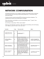
1
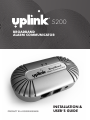
®
5200
BROADBAND
ALARM COMMUNICATOR
PRODUCT ID # 2033325200XX00
INSTALLATION &
USER’S GUIDE
5200
© 2013 Uplink Security, LLC. All rights reserved. Uplink is a trademark of Uplink Security, LLC.
No part of this publication may be reproduced or used in any form without permission
in writing from Uplink. This includes electronic or mechanical means, such as
photocopying, recording, or information storage and retrieval systems. The material in
this manual is subject to change without notice.
Uplink reserves the right to make changes to any software or product to improve
reliability, function or design.
Uplink is a registered trademark of Uplink Security, LLC. All other trademarks are the
property of their respective owners.
PRODUCT ID # 2033325200XX00
BROADBAND
ALARM COMMUNICATOR
®
BROADBAND
ALARM COMMUNICATOR
TABLE OF CONTENTS
Table of Contents.....................................................................................2
Introduction..............................................................................................3
Installation................................................................................................4
Connections Used....................................................................................5
Activation..................................................................................................6
Network Configuration.............................................................................7
Dialing The Alarm System For
Touch-Tone Phone Remote
Control & Upload And Download
Over Dial Up Connection..........................................................................8
Troubleshooting........................................................................................9-10
Standard 12-Month Limited Warranty......................................................11-12
Fcc & Industry Canada Regulatory Compliance......................................13
FCC RF Exposure Information.................................................................14
Technical Support.....................................................................................15
2
®
5200
Introduction
The Uplink® 5200 Broadband communicator expands the capability of a Contact
ID dial-up alarm system by enabling it to transmit signals over the internet. It is a
cost-effective solution where there is broadband internet service. The 5200 can be
used for retrofits on existing alarm systems, takeovers and new installations.
The 5200 converts the dialer output of an alarm system to an IP signal that can
be transmitted securely over the internet to an Uplink server. A connection is then
made to the central station to deliver the alarm signal. The 5200 supports two-way
voice sessions as well as remote programming for most systems.
Installation is fast and easy. Using the provided cables, the 5200 communicator is
hardwired between alarm dialer and internet service.
3
BROADBAND
ALARM COMMUNICATOR
INSTALLATION
The physical installation of the Uplink 5200 is simple, but it is important to plan
it beforehand. The unit requires power, a connection to the alarm panel, and a
connection to the Internet. Choose a location where the 5200 can be connected
to all of these things. In most cases, the 5200 should be placed near the alarm
panel, but in some installations it may be easier to place it near the router and run
a long phone cord to the alarm panel. Connect the Alarm Broadband Adapter
to the Internet using either an Ethernet cord to the router, a wireless bridge, or a
power line bridge. (If the alarm panel was connected to a multi-pair phone line with
line seizure, the line-seizure pair can be used as a phone connection between the
panel and a phone jack near the customer’s router)
4
®
5200
CONNECTIONS USED
LAN (RJ45 included).....................
PHONE (RJ11)..............................
POWER.........................................
Connection to an internet router
Connection to alarm system
Power adapter connection or 12V DC power
1. Connect one end of an RJ45 Ethernet cable to the “LAN” port of the 5200 and connect the other end to the Internet Router or Modem in the premises
NOTE: THE 5200 MAY BE LOCATED BY THE ALARM SYSTEM OR BY THE ROUTER. ADDITIONAL CABLING, NOT INCLUDED, MAY BE NECESSARY.
2. Connect the power adapter to the “POWER” and plug the adapter into a wall outlet.
The 5200 may also use other sources of 12V DC power such as an alarm system
or battery instead of the included transformer. The 5200 will use as much as 300mA
when the device is communicating an alarm signal.
3. Configuration and registration of the device may take 2 minutes. Do not proceed
until the LED on the right is lit steady green with an occasional flash of amber.
NOTE: DO NOT POWER CYCLE THE 5200 DURING SYSTEM BOOT UP.
4. Connect the alarm system to the “PHONE” port of the 5200 using a standard twowire RJ11 cord (only tip & ring required).
5. IF using an RJ31X connection, use the in-line adapter and cord included with the
5200 (which will close the Tamper Loop)
a. Plug the short black cord extending from the in-line adapter into the “PHONE”
port on the 5200
b. Plug the RJ31X cord into the opposite end of the adapter
c. RJ11 cable into the port “PHONE”
5
BROADBAND
ALARM COMMUNICATOR
ACTIVATION
1. Activate the unit on the Uplink Dealer Portal with the full ten digit unit serial number.
The unit serial number begins with “B” and is found on the box label and device label.
a. Enter the unit name and tracking number for your reference
b. Enter the Panel make and model connected to the unit
c. Select the panel test interval: none/daily/weekly
d. Select service class: Standard or Two-way voice Verification System
e. Select Central Station receiver type: Contact ID dial-up or IP
NOTE: MUST BE CONTACT ID DIAL UP FOR TWO-WAY VOICE.
f. Enter a Central Station Receiver Phone Number
• This will override any receiver phone number in the alarm panel
• This number will be used if Contact ID over IP fails
g. Enter the Central Station account number
• This will override any in the alarm panel
h. Internet Connection Fault Notifications
• Select Notify on Internet Connection Lost: Yes/No
• Select Notify on Connection Restoral: Yes/No
2. To test the unit’s registration status, select Send Status Request Signal from the “Test”
tab on the Uplink Dealer web site. View device registration status.
6
®
5200
NETWORK CONFIGURATION
All settings in the 5200 can be changed by plugging a standard touchtone telephone
into the PHONE port and using a simple voice prompt menu. To access the menu,
follow these steps.
Unplug your alarm system from the 5200 and plug in a touchtone telephone. The
phone should connect to the PHONE port on the 5200.
Pick up the phone, and whether or not you hear dial tone, press *** (press * three
times on the phone).
You will hear a voice prompt: “Enter a menu option.”
Enter any of the following commands. After entering a new setting, such as changing
the IP address, press # to return to the main menu.
To do this
Press
Then press this
Toggle between static
and dynamic IP mode
01
9, then # to return to
the main menu
02
The voice will read off the
adapter’s current IP address. Type
in a new IP address if a static
address is desired, using 3-digit
octets. For example, to set the IP
address as 192.168.1.20, enter
“192168001020”, then press #.
In order to change the IP
address, the adapter must
be set to static IP mode first.
03
The voice will read off the adapter’s
current subnet. Type in a new
subnet if desired, using 3-digit
octets. For example, to set the
subnet address as 255.255.255.0
enter “255255255000”, then press #.
The adapter must be set to
static IP mode first.
04
The voice will read off the adapter’s
gateway. Type in a new gateway if
desired, using 3-digit octets. For
example, to set the gateway as
192.168.1.1, enter “192168001001”,
then press #.
The adapter must be set to
static IP mode first.
Check or change
the adapter’s current
IP address
Check or change the
network mask (subnet)
Check or change the
gateway address
7
Notes
BROADBAND
ALARM COMMUNICATOR
DIALING THE ALARM SYSTEM
FOR TOUCH-TONE PHONE
REMOTE CONTROL & UPLOAD
AND DOWNLOAD OVER DIAL UP
CONNECTION
Dial-up touch-tone remote control of alarm systems is possible for most
systems that support the function.
To dial an alarm system connected to the 5200, dial 770-944-4601, wait for a
second dial-tone, and dial the last nine digits of the 5200 unit/serial number.
Follow the directions in the alarm system manual for next steps and commands.
Dial-up uploading and downloading of alarm systems is possible for most
systems that support the function.
To dial an alarm system connected to the 5200, dial 770-944-4601, wait for a
second dial-tone, and dial the last nine digits of the 5200 unit/serial number. The
downloader entry for the phone number would be “7709444601,,,, (nine digit unit/
serial number)”.
8
®
5200
TROUBLESHOOTING
Environments with VoIP phone service
If the existing 5200 is connected directly to a single port cable or DSL modem,
then disconnect it, and connect it to a router instead. The router should be the
only device connected directly to the cable or DSL modem. If the customer’s VoIP
phone service no longer works after doing this, then the VoIP provider will need to
assist you or the customer in reconfiguring their device to work with a router.
Check that all wires are connected and secure.
Unplug then plug back in the Alarm Broadband Adapter’s power cord, Ethernet
cord, and phone cord. Make sure that the Ethernet cord is plugged into an
open Ethernet port on your router or wireless bridge, and that the phone cord is
connected to the Phone jack port and the phone jack on your alarm system.
If you have assigned a static IP address to the Alarm Broadband Adapter,
make sure the address is not already in use.
By default, the 5200 automatically requests an IP address via DHCP. In most
cases, we recommend leaving the adapter set for DHCP. In some unusual
network configurations, it may be necessary to set the 5200 to use a static IP
instead. If two devices on your customer’s network have the same IP address,
then both devices will frequently lose their connection to the Internet. If you
have set a static IP address for the 5200, and you believe another device has the
same IP address, then change the IP address of the 5200. Every device on your
customer’s network should have its own unique IP address.
Update the router firmware.
9
It is important that the customer’s router is using the latest firmware provided
by its manufacturer. Router firmware can usually be downloaded from the
manufacturer’s website, and installed using the router’s web interface. Your
Continued on next page
BROADBAND
ALARM COMMUNICATOR
TROUBLESHOOTING (cont.)
customer can contact the router manufacturer for assistance in updating its
firmware, if needed.
Are there two routers?
If there are two routers connected to the network, then some devices will have
trouble staying connected to the Internet. To fix this, turn off routing (DHCP) on
the router that is not connected directly to your cable or DSL modem. Only one
router should give IP addresses to devices on the network.
Are you using a wireless bridge?
Wireless Ethernet bridges such as the Uplink® 5300 can make installing the
Uplink 5200 easy by eliminating the need to use an Ethernet cable. However, if
WiFi signal is poor or the unit is not correctly set up, then they can cause many
connection problems.
If you are using a wireless bridge, then remove the bridge and connect the
Alarm Broadband Adapter directly to the router. This is a test only, to eliminate
the bridge as a potential problem. You do not need to connect the alarm system
to the Alarm Broadband Adapter during this test. Simply connect the Alarm
Broadband Adapter directly to the router for about 30 minutes, and see if the
connection stays on.
Does your customer use a Linksys router?
If your customer uses a Linksys router such as the Linksys WRTP54G, then one of
its security settings may interfere with the 5200’s operation. Log into your router
using a web browser, click on the Security tab, and turn off “Block Anonymous
Internet Requests”.
10
®
5200
Standard 12-Month
Limited Warranty
Uplink Security, LLC’s limited product warranty extends only to commercial distributors
who purchase products directly from Uplink. Uplink’s warranty does not extend to end user
consumers of Uplink products or to other parties not in privity of contract with Uplink and,
to the maximum extend permissible under applicable law, Uplink expressly disclaims any
warranty, express or implied, extending to such end user consumer or parties including without
limitations, any implied warranties or merchantability and fitness for a particular purpose. End
user consumers with questions concerning an Uplink product are directed to contact the alarm/
security system dealer or installer from whom they purchased the product.
Distributors, dealers and installers with questions about Uplink’s warranty and returns process
are directed to contact Uplink Order Entry; issuance of a Return Merchandise Authorization
(RMA) number by Uplink is required as a condition prerequisite to the return of any Uplink
products under the applicable product warranty.
IN NO EVENT SHALL UPLINK OR ANY OF ITS REPRESENTATIVES BE LIABLE TO ANY END
USER CONSUMER OF AN UPLINK PRODUCT AND/OR SERVICE OR ANY OTHER PARTY
NOT IN PRIVITY OF CONTRACT WITH UPLINK FOR ANY CONSEQUENTIAL, INCIDENTAL,
INDIRECT, EXEMPLARY, SPECIAL OR PUNITIVE DAMAGES, INCLUDING ANY DAMAGES
FOR BUSINESS INTERRUPTION, LOSS OF USE, DATA, REVENUE OR PROFIT, WHETHER
ARISING OUT OF BREAK OF CONTRACT, TORT (INCLUDING NEGLIGENCE OR PRODUCT
LIABILITY) OR OTHERWISE, REGARDLESS OF WHETHER SUCH DAMAGES WERE
FORESEEABLE AND WHETHER OR NOT UPLINK WAS ADVISED OF THE POSSIBILITY OF
SUCH DAMAGES.
Continued on next page
11
BROADBAND
ALARM COMMUNICATOR
Standard 12-Month Limited
Warranty (cont.)
IN NO EVENT SHALL UPLINK’S AGGREGATE LIABILITY TO ANY END USER CONSUMER
OF AN UPLINK PRODUCT AND/OR SERVICE OR OTHER PARTY NOT IN PRIVITY OF
CONTRACT WITH UPLINK ARISING OUT OF OR RELATED TO AN UPLINK PRODUCT
AND/OR SERVICE, WHETHER ARISING OUT OF OR RELATED TO BREAK OF CONTRACT,
TORT (INCLUDING, WITHOUT LIMITATION, NEGLIGENCE OR PRODUCT LIABILITY)
OR OTHERWISE, EXCEED THE TOTAL AMOUNT PAID OR PAYABLE TO THE ALARM/
SECURITY DEALER OR INSTALLER BY THE END USER CONSUMER FOR SAID PRODUCT
AND/OR SERVICE IN THE 12 MONTH PERIOD PRECEDING THE EVENT GIVING RISE TO
THE CLAIM OR $250, WHICHEVER AMOUNT IS GREATER.
12
®
5200
FCC & Industry Canada
Regulatory Compliance
Part 15
This device complies with Part 15 of the FCC Rules. Operation is subject to the
following two conditions: (1) this device may not cause harmful interference, and
(2) this device must accept any interference received, including interference that
may cause undesired operation.
This equipment has been tested and found to comply with the limits for a Class
B digital device, pursuant to Part 15 of the FCC Rules. These limits are designed
to provide reasonable protection against harmful interference in a residential
installation. This equipment generates, uses, and can radiate radio frequency
energy and, if not installed and used in accordance with the instructions, may
cause harmful interference to radio communications.
However, there is no guarantee that interference will not occur in a particular
installation. If this equipment does cause harmful interference to radio or television
reception, which can be determined by turning the equipment off and on, the user
is encouraged to try to correct the interference by one or more of the following
measures:
• Reorient or relocate the receiving antenna.
• Increase the separation between the equipment and receiver.
• Connect the equipment into an outlet on a circuit different from that to which the
receiver is connected.
• Consult the dealer or an experienced technician for help.
13
BROADBAND
ALARM COMMUNICATOR
TECHNICAL SUPPORT
Technical support is available Monday through Friday, 8:00 AM to 8:00 PM ET excluding holidays. Before calling technical support, please ensure you have read
the installation guide completely. Technical support requires the caller to provide:
Login name & password for the Uplink Dealer Portal
Serial number of the 5200
UPLINK Security, LLC.
3330 Cumberland Blvd.
Suite 700
Atlanta, GA 30339
888-9-Uplink (888-987-5465)
www.uplink.com
14
®
FOR SALES, PRODUCT
INFORMATION &
TECHNICAL SUPPORT
Uplink
3330 Cumberland Blvd.
Suite 700
Atlanta, GA 30339
1-(888) 9-UPLINK, 1-(888)-987-5465
Fax 1-(888)-542-9105
[email protected]
www.uplink.com