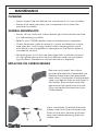
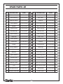
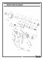
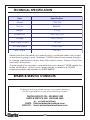
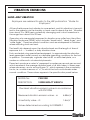
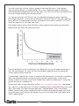
1
ELECTRIC IMPACT WRENCH
Model No.CEW1000
PART NO:6480300
OPERATING & MAINTENANCE
INSTRUCTIONS
12/08
INTRODUCTION
Thank you for purchasing this CLARKE Impact Wrench.
Before attempting to use the machine, please read this manual thoroughly
and follow the instructions carefully. In doing so you will ensure the safety of
yourself and that of others around you, and you can look forward to your
purchase giving you long and satisfactory service.
GUARANTEE
This product is guaranteed against faulty manufacture for a period of 12
months from the date of purchase. Please keep your receipt which will be
required as proof of purchase.
This guarantee is invalid if the product is found to have been abused or
tampered with in any way, or not used for the purpose for which it was
intended.
Faulty goods should be returned to their place of purchase, no product can
be returned to us without prior permission.
This guarantee does not effect your statutory rights.
ENVIRONMENTAL PROTECTION
Do not dispose of this product with general household waste. It must be
disposed of according to the laws governing Waste Electrical and
Electronic Equipment, at a recognised disposal facility.
CONTENTS
When unpacking, check for damage and /or shortages etc. Any found
should be reported to your CLARKE dealer where the appliance was originally purchased. This CEW1000 Impact Wrench is delivered supplied with the
following components:
•
Impact Wrench
•
1 x 17mm Socket, Chrome Vanadium, black
•
1 x 19mm Socket, Chrome Vanadium, black
•
1 x 21mm Socket, Chrome Vanadium, black
•
1 x 22mm Socket, Chrome Vanadium, black
•
Blow-Moulded Case
2
TABLE OF CONTENTS
INTRODUCTION .................................................................................. 2
GUARANTEE ........................................................................................ 2
IN THE BOX ......................................................................................... 2
ENVIRONMENTAL PROTECTION ......................................................... 2
TABLE OF CONTENTS .......................................................................... 3
GENERAL SAFETY RULES ..................................................................... 4
IMPACT WRENCH SAFETY INSTRUCTIONS .......................................... 6
ELECTRICAL CONNECTIONS .............................................................. 7
OVERVIEW .......................................................................................... 8
OPERATING INSTRUCTIONS ................................................................ 9
MAINTENANCE ................................................................................... 10
FAULT FINDING ................................................................................... 11
SPARE PARTS LIST & DIAGRAM ........................................................... 13
TECHNICAL SPECIFICATION ............................................................... 14
SPARES & SERVICE CONTACTS ........................................................... 14
VIBRATION EMISSIONS ....................................................................... 15
DECLARATION OF CONFORMITY ....................................................... 17
NOTES ................................................................................................. 18
3
GENERAL SAFETY RULES
1)
WORK AREA
1. Keep the work area clean and well lit. Cluttered and dark areas invite
accidents.
2. Do not operate power tools in explosive atmospheres such as in the
presence of flammable liquids, gasses or dust. Power tools create sparks
which may ignite dust or fumes.
3. Keep children and bystanders away while operating a power tool. Distractions can cause you to loose control.
2)
ELECTRICAL SAFETY
1. Power tools must match the power outlet. Never modify the plug in any
way. Do not use adaptor plugs with earthed (grounded) power tools.
Correct plugs and outlets will reduce the risk of electric shock.
2. Do not expose power tools to rain or wet conditions. Any water entering
power tools will increase the risk of electric shock.
3. Do not abuse the electrical cable. Never use the cord for pulling or unplugging the power tool. Keep the cable away from sources of heat, oil,
sharp edges or moving parts. Damaged or tangled cables increase the
risk of electric shock.
4. When operating a power tool outdoors, use an extension cable suitable
for outdoor use. Using the correct cable reduces the risk of electric shock.
3)
PERSONAL SAFETY
1. Stay alert, watch what you are doing and use common sense when you
are operating a power tool. Do not operate a power tool when you are
tired, ill or under the influence of alcohol, drugs or medication.
2. Wear personal protective equipment including eye protection. Safety
equipment such as a dust mask, non-skid shoes or hearing protection used
for appropriate conditions will reduce injuries. Use a face or dust mask if
operation is particularly dusty. Wear ear protectors/defenders as the noise
level of this machine can exceed 85dB (A).
3. Do not over-reach. Keep your proper footing and balance at all times. This
enables better control of the power tool in unexpected situations.
4. Avoid accidental starting of the machine. Ensure the switch is in the off
position and the locking button disengaged before plugging the machine
in to the power supply. Carrying power tools around with your finger on
the trigger or plugging in power tools that are switched on invites accidents.
5. Remove any adjusting key or wrench before turning the power tool on. A
tool left attached to a moving part may result in injury.
4
6. Dress properly. Do not wear loose clothing or jewellery which may get
caught in moving parts. Wear protective hair covering to contain long
hair. For best footing, wear rubber soled footwear. Keep floor clear of oil,
scrap wood, etc.
7
Concentrate on the job in hand, no matter how trivial it may seem. Be
aware that accidents are caused by carelessness due to familiarity.
8. Switch the machine OFF immediately after the task is completed.
4)
POWER TOOL USE AND CARE
1. Do not force the machine. Use the correct power tool for your application.
It will do a better and safer job at the rate for which it was designed.
2. Do not use the power tool if the switch does not turn it on and off. Any
power tool that cannot be controlled with the switch is dangerous and
must be repaired.
3. Disconnect the power tool from the power supply before making any
adjustments, changing accessories, or storing the tool. These measures will
reduce the risk of the power tool starting accidently.
4. Store power tools out of the reach of children and do not allow persons
unfamiliar with these instructions to operate the power tool. Power tools
are potentially dangerous in the hands of untrained users.
5. Maintain power tools in top condition. Keep tools/ machines clean for the
best and safest performance. Check for misalignment or binding of
moving parts, broken parts, or any condition that may affect the power
tool’s operation. If damaged, have the power tool repaired before use.
Many accidents are caused by poorly maintained power tools.
6. Use recommended accessories. The use of improper accessories could be
hazardous.
7. Machine cleanliness. Do not allow the ventilation slots in the machine to
become blocked with dust.
8. Check the power tool for damage before using the machine. Any damaged part should be inspected to ensure that it will operate properly and
perform its intended function. Check for alignment of moving parts,
breakage of parts, mountings, and any other condition that may affect
the machine’s operation. Any damage should be properly repaired or
the part replaced. If in doubt, DO NOT use the machine. Consult your
local dealer.
5)
SERVICE
1. When necessary, have your power tools serviced or repaired by a qualified person using identical replacement parts. This will ensure that the
safety of the power tool is maintained.
5
IMPACT WRENCH SAFETY INSTRUCTIONS
1. Use the wrench correctly. Only use the impact wrench in the manner and
for the functions described in these instructions.
2. Changing Sockets. Always disconnect the machine from the power
supply when changing sockets etc. Use only Impact Wrench sockets....DO
NOT use standard sockets.
3. Achieve the correct torque. Always finish tightening wheel nuts with a
torque wrench or suitable spanner to the wheel-nut torque as recommended by the vehicle manufacturer.
4. Avoid excessive use of the wrench. When tightening a nut or bolt, never
allow the wrench to impact more than 8 times - to avoid over tightening 3 to 4 impacts is sufficient.
5. Care of the mains cable. Keep the mains cable well away from the
machine and ensure an adequate electrical supply is close at hand so
that the operation is not restricted by the length of the cable.
6. Use outdoor extension leads. If working outdoors, always use an approved
cable extension suitable for the power rating of this tool (see specifications), the conductor size should also be at least the same size as that on
the machine, or larger. When using a cable reel, always unwind the cable
completely.
Additionally, please keep these instructions in a safe place for future reference.
6
ELECTRICAL CONNECTIONS
This product is provided with a 13 amp, 230 volt (50Hz), BS 1363 plug, for
connection to a standard, domestic electrical supply. Should the plug need
changing at any time, ensure that a plug of identical specification is used.
WARNING: THIS APPLIANCE IS OF DOUBLE INSULATED DESIGN
No earth conductor is provided. The two wires in the mains lead should be
wired in accordance with the following colour code:
Blue
Brown
—
—
Neutral
Live
Connect the BROWN coloured cord to the plug terminal marked a letter “L”
Connect the BLUE coloured cord to the plug terminal marked a letter “N”
If this appliance is fitted with a plug which is moulded on to the electric cable
(i.e. non-rewireable) please note:
1. The plug must be thrown away if it is cut from the electric cable. There is a
danger of electric shock if it is subsequently inserted into a socket outlet.
2. Never use the plug without the fuse cover fitted.
3. Should you wish to replace a detachable fuse carrier, ensure that the
correct replacement is used (as indicated by marking or colour code).
4. Replacement fuse covers can be obtained from your local Clarke dealer
or most electrical stockists.
FUSE RATING
The fuse in the plug must be replaced with one of the same rating and this
replacement must be ASTA approved to BS1362.
If in any doubt, consult a qualified electrician. DO NOT attempt any electrical
repairs yourself.
CABLE EXTENSION
Always use an approved cable extension suitable for the power rating of this
tool (see specifications), the conductor size should also be at least the same
size as that on the machine, or larger. When using a cable reel, always
unwind the cable completely.
7
OVERVIEW
The CLARKE CEW1000 Impact Wrench is equipped with a 3-position Forward/
Reverse/Neutral trigger switch (item 4 below). When trigger is squeezed
downwards, rotation is forward (clockwise). When squeezed upwards, rotation is reversed (anti-clockwise), and when in the centre position the tool is
stopped.
1.
1/2" Square Socket Drive
2.
Metal Gear Housing
3.
Ventilation Slots
4.
Forward / Reverse Trigger Switch
5.
Hand Grip
6.
Plug & Cable
7.
Brush replacement openings
8.
Sockets
8
OPERATING INSTRUCTIONS
ALWAYS ENSURE THAT THE MACHINE IS DISCONNECTED FROM THE
POWER SUPPLY BEFORE CHANGING THE SOCKET.
LOOSENING A NUT
1. Remove any wheel trim, before selecting the appropriate socket and
placing firmly on the square drive of the wrench.
2. Select the appropriate socket and place firmly on the square drive of the
wrench. Holding the wrench firmly in BOTH HANDS, pull the rocker switch
at ‘L’ marked on the casing. The torque will build up and impact the nut
repeatedly until the nut is loosened.
3. With the FORWARD/NEUTRAL/REVERSE switch in the REVERSE position, and
holding the wrench firmly in BOTH HANDS, pull the trigger fully. The nut will
be impacted repeatedly until it is loosened. IMPORTANT! Release the
trigger immediately the nut begins to loosen.
4. Jack up the vehicle according to the vehicles handbook so that the
wheel is clear of the ground, then proceed to fully undo the wheel nuts..
ENSURE THAT THE CORRECT SOCKET IS BEING USED FOR THE NUTS ON
YOUR PARTICULAR VEHICLE. AN INCORRECT SOCKET SIZE IS LIKELY TO
DAMAGE THE HEADS OF THE BOLTS/NUTS.
TIGHTENING A NUT
1
Start the nut by hand, ensuring it is not cross threaded, then with the
appropriate socket installed on the wrench, place it on the nut.
2. With the FORWARD/NEUTRAL/REVERSE switch in the FORWARD position,
and holding the wrench firmly in BOTH HANDS, pull the trigger gently. You
can vary the spindle speed by modulating finger pressure on the trigger.
3. Run each nut up in turn until it is ‘nipped’ up only - do not tighten - do not
fully depress the trigger. When all nuts are nipped up, tighten progressively
by pulling the trigger fully and allowing the action to operate for 3 to 4
impacts only to prevent overtightening.
4. ALWAYS finish tightening with a torque wrench or suitable spanner. The
weight of the vehicle will need to be placed on the wheel to prevent it
from rotating while the nuts are tightened. Ensure the final torque applied
to the nuts meets the vehicle manufacturers recommendations.
9
MAINTENANCE
CLEANING
• Always inspect the tool before use, and ensure it is in top condition.
• Ensure all air vents are clear, (use compressed air to clean the
machine if possible).
GENERAL MAINTENANCE
• Ensure all nuts, bolts and screws remain tight to ensure the machine
is in safe working condition.
• Refer to your CLARKE dealer if internal maintenance is required.
• Check the power cable to ensure it is sound and free from cracks,
bare wires etc. avoid using solvents when cleaning plastic parts,
most plastics are susceptible to damage from the various types of
commercial solvents.
• All bearings etc, in this tool are lubricated with a sufficient amount
of high grade lubricant for the tools lifetime under normal operating conditions, therefore no further lubrication is required.
REPLACING THE CARBON BRUSHES
Remove and inspect the carbon
brushes after periods of extended use.
Replace them when they eventually
wear down. The brushes should be kept
clean and free to slide up and down in
the holders. Both brushes should be
replaced at the same time as a pair.
Only use identical brushes from your
Clarke dealer.
Use a screwdriver to remove the brush
holder covers from the machine body.
Draw out the worn brushes and insert
new ones before replacing the brush
holder caps.
10
STORAGE
1. Make sure that the tool is stored in a clean, dry place, out of reach of
children when not in use.
2. Always store the impact wrench and its sockets in the case supplied.
FAULT FINDING
MACHINE DOES NOT OPERATE WHEN SWITCHED ON
Check to ensure the fuse is sound and replace if necessary. If the fuse is
sound or blows repeatedly, consult your CLARKE dealer.
EXCESSIVE SPARKING OCCURS
This indicates worn brushes. This problem is quickly remedied by replacing the
brushes as page 10, or alternatively consult your CLARKE dealer for their
replacement.
11
SPARE PARTS LIST
NO
DESCRIPTION
CODE
Qty
NO
DESCRIPTION
CODE
Qty
1
Plastic Collar
GTCIR130301
1
23
Spindle
GTCIR130323
1
2
Gear Housing
GTCIR130302
1
24
Spur Gear
GTCIR130324
1
3
Bearing Sleeve
GTCIR130303
1
25
Bearing
GTCIR130325
2
4
Thrust Washer
GTCIR130304
1
26
Cross-head Screw
GTCIR130326
2
5
Spindle
GTCIR130305
1
27
Stator Assembly
GTCIR130327
1
6
Impact Driver
GTCIR130306
1
28
Motor Bearing
GTCIR130328
1
7
Ball Bearings
GTCIR130307
24
29
Bearing Cap
GTCIR130329
1
8
Impact Spring
GTCIR130308
1
30
Main Housing
GTCIR130330
1
9
Steel Ball
GTCIR130309
2
31
Rear Cover
GTCIR130331
1
10
Clutch Spindle
GTCIR130310
1
32
Cross-head Screw
GTCIR130332
4
11
Large Gear
GTCIR130311
1
33
Inductor
GTCIR130333
1
12
Screw
GTCIR130312
4
34
On/Off Switch
GTCIR130334
1
13
Spring Washer
GTCIR130313
4
35
Hand Grip
GTCIR130335
1
14
Washer
GTCIR130314
3
36
Cross-head Screw
GTCIR130336
2
15
Ball-race
GTCIR130315
1
37
Cross-head Screw
GTCIR130337
2
16
Paper Gasket
GTCIR130316
1
38
Connecting block
GTCIR130338
1
17
Centre Cover
GTCIR130317
1
39
Anchor Block
GTCIR130339
1
18
Bearing
GTCIR130318
1
40
Cable Entry Sleeve
GTCIR130340
1
19
Bearing Cover
GTCIR130319
1
41 Cable/ Plug Assembly GTCIR130341
1
20
F an
GTCIR130320
1
42
Motor Brush Holder
GTCIR130342
2
21
Air-tight Closure
GTCIR130321
1
43
Motor Brush
GTCIR130343
2
22
Armature Assembly
GTCIR130322
1
44
Brush Cover
GTCIR130344
2
12
SPARE PARTS DIAGRAM
13
TECHNICAL SPECIFICATION
Item
Specification
Model
CEW1000
Part No
6480300
Weight
3.9 kg
Dimensions
295 x 95 x 230
Voltage
230v / 50 Hz
Max Power Output
1.01 kw
No-load Speed
0-2000 rpm
Max Torque
450 Nm
Please note that the details and specifications contained herein, are correct
at the time of going to print. However, CLARKE International reserve the right
to change specifications at any time without prior notice. Always consult the
machine’s data plate.
A wide range of accessories is available from your nearest CLARKE dealer, for
further information, contact your nearest dealer, or telephone CLARKE
International Sales department on 01992 565300.
SPARES & SERVICE CONTACTS
For parts & Servicing, please contact your nearest dealer, or
CLARKE International, on one of the following numbers.
PARTS & SERVICE TEL: 020 8988 7400
PARTS & SERVICE FAX: 020 8558 3622
or e-mail as follows:
PARTS: [email protected]
SERVICE: [email protected]
14
VIBRATION EMISSIONS
HAND-ARM VIBRATION
Employers are advised to refer to the HSE publication “Guide for
Employers”.
All hand held power tools vibrate to some extent, and this vibration is transmitted to the operator via the handle, or hand used to steady the tool. Vibration
from about 2 to 1500 herz is potentially damaging and is most hazardous in
the range from about 5 to 20 herz.
Operators who are regularly exposed to vibration may suffer from Hand Arm
Vibration Syndrome (HAVS), which includes ‘dead hand’, ‘dead finger’, and
‘white finger’. These are painful conditions and are widespread in industries
where vibrating tools are used.
The health risk depends upon the vibration level and the length of time of
exposure to it……in effect, a daily vibration dose.
Tools are tested using specialised equipment, to approximate the vibration
level generated under normal, acceptable operating conditions for the tool
in question. For example, a grinder used at 45° on mild steel plate, or a
sander on softwood in a horizontal plane etc.
These tests produce a value‘a’, expressed in metres per second per second,
which represents the average vibration level of all tests taken, in three axes
where necessary, and a second figure ‘K’, which represents the uncertainty
factor, i.e. a value in excess of ‘a’, to which the tool could vibrate under
normal conditions. These values appear in the specification panel below.
MODEL No:
CEW1000
DESCRIPTION:
1000W IMPACT WRENCH
Declared vibration emission value in accordance
with EN12096
Measured vibration emission value - a:
6.55m/s2
Uncertainty value - K:
1.5m/s2
Values determined according to EN28622-1
15
You will note that a third value is given in the specification - the highest
measured reading in a single plane. This is the maximum level of vibration
measured during testing in one of the axes, and this should also be taken into
account when making a risk assessment.
‘a’ values in excess of 2.5 m/s2 are considered hazardous when used for
prolonged periods. A tool with a vibration value of 2.8 m/s2 may be used for
up to 8 hours (cumulative) per day, whereas a tool with a value of 11.2 m/s2
may be used for ½ hour per day only.
The graph below shows the vibration value against the maximum time the
respective tool may be used, per day.
The uncertainty factor should also be taken into account when assessing a
risk. The two figures ‘a’ and ‘K’may be added together and the resultant
value used to assess the risk.
It should be noted that if a tool is used under abnormal, or unusual conditions,
then the vibration level could possibly increase significantly. Users must
always take this into account and make their own risk assessment, using the
graph above as a reference.
Some tools with a high vibration value, such as impact wrenches, are generally used for a few seconds at a time, therefore the cumulative time may only
be in the order of a few minutes per day. Nevertheless, the cumulative
effect, particularly when added to that of other hand held power tools that
may be used, must always be taken into account when the total daily dose
rate is determined.
16
DECLARATION OF CONFORMITY
DECLARATION OF CONFORMITY
This is an important document and should be retained.
We declare that this product complies with the following directives:
2004/108/EC
Electromagnetic Compatibility directive
2006/95/EC
Low Voltage Equipment directive
2002/95/EC
Restriction of Hazardous Substances
The Following Standards have been applied to the product:
BS EN 55014-1:2006
BS EN 55014-2:1997+A1
BS EN 61000-3-3:1995+A1 +A2
BS EN 61000-3-2:2006
BS EN 60745-1:2006
BS EN 60745-2-2:2003+A11
The technical documentation required to demonstrate that the products meet the
requirements of the Low Voltage Equipment directive has been compiled and is available
for inspection by the relevant enforcement authorities.
The CE mark was first applied in: 2008
Product Description:
Electric Impact Wrench (1000W)
Model number(s):
CEW1000
Serial / batch Number:
Current Manufacture.
Date of Issue:
15/07/2008
Signed
A.C. AIKEN
Senior Manager Clarke International.
07-0878 impact wrench RV1.doc
Page 1 of 1
17
NOTES
___________________________________________________________________________
__________________________________________________________________________
__________________________________________________________________________
__________________________________________________________________________
__________________________________________________________________________
__________________________________________________________________________
__________________________________________________________________________
__________________________________________________________________________
__________________________________________________________________________
__________________________________________________________________________
__________________________________________________________________________
__________________________________________________________________________
__________________________________________________________________________
__________________________________________________________________________
__________________________________________________________________________
18
NOTES
___________________________________________________________________________
__________________________________________________________________________
__________________________________________________________________________
__________________________________________________________________________
__________________________________________________________________________
__________________________________________________________________________
__________________________________________________________________________
__________________________________________________________________________
__________________________________________________________________________
__________________________________________________________________________
__________________________________________________________________________
__________________________________________________________________________
__________________________________________________________________________
__________________________________________________________________________
__________________________________________________________________________
19