1
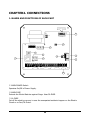
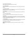
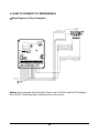
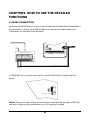
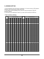
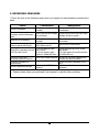
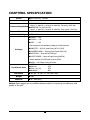
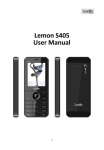
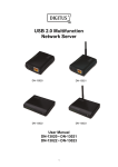
CCTV RECEIVER
USER MANUAL
DRX-500
DONGYANG UNITECH
WARNING
Always have the unit installed by the store it was purchased from.
z Improper connections and/or installation could result in electrical shock, fire or
other serious injury or damage.
Do not place the unit on an unstable surface.
z Always checks the strength and stability of the installation location.
z A falling unit will result in damage and could cause serious injury.
Never disassemble or attempt to repair or modify the unit.
z Disassemble by untrained personnel could result in serious electrical shock, fire
and/or malfunction.
Never use in locations where combustible materials are used.
z The unit should never be used where combustible materials, such as gases, are
being used.
z Fire, explosion or other serious accidents could occur
Never touch electrical connections with wet hands.
z Touching electrical connections with wet hands could result in serious electrical
shock.
Never expose the unit to water.
z If the unit becomes wet, turn off the power and unplug it immediately.
z Stop using the unit if it becomes wet and contact your nearest supplier or
manufacturer representative.
Never use the unit if there is an abnormality.
z Turn off the power and unplug the unit immediately if there is any type of
abnormality, such as a strange smell or smoke.
z Continuing to use a unit that is not operation properly could result in serious injury
or damage to the unit.
Always use the designated power supply.
z Failure to use the proper power supply could result in fire, electrical shock, serious
injury and/or damage.
z Always uses the designated power supply.
Always handle the connecting cords properly.
z Never damage or modify the connecting cords.
z Never pull on the connecting cord, expose them to extreme heat and/or place
heavy objects on top of them.
z Failure to follow these warnings could result in fire, electrical shock or other
damage or injury.
2
CAUTION
Always use the unit indoors.
z The unit should never be used outdoors, or in any place where it will be exposed to
rain or other extremes of moisture.
z Direct exposure to water will result in rust and will damage the unit.
Never use in environments that have heavy concentrations of dust, smoke, steam or
humidity.
z Environments such as these could result in fire, electrical shock or other serious
damage or injury.
Never place the unit in extremes of high or low temperatures.
z Extreme temperatures will damage the unit.
z Always use within an operating range of -15℃ to 60℃
Never place the unit near the magnetic.
z The unit should never be placed near by magnetic.
z It is reason for the malfunctions.
Never expose the unit to impact.
z Strong impact may seriously damage the unit.
FOR PROPER OPERATION
Never install the unit yourself.
z The unit should be installed by trained personnel.
This product has been designed and manufactured in accordance with the harmonized European
standards, following the provisions of the below stated directives.
Low Voltage Directive 73/23/EEC & Electromagnetic Compatibility Directive
89/336/EEC(EN60065, EN50130-4, EN55022, EN61000-4-2, 3, 4, 5, 6, 11)
This devise complies with part 15 of the fcc rules operation is subject to the following two conditions: (1)
This device may not cause harmful interference and (2) This device must accept any interference received
including interference that may cause undesired operation
3
Table of Content
CHAPTER1. INTRODUCTION
4
1. FEATURES
4
CHAPTER2. CONNECTIONS
1. NAMES AND FUNCTIONS OF EACH PART
5
2. HOW TO CONNECT TO PERIPHERALS
7
CHAPTER3. HOW TO USE THE DETAILED FUNCTIONS
8
1. RS485 CONNECTION
8
2. RS422 CONNECTION
9
3. ADDRESS SETTING
10
CHAPTER4. NOTICE
11
1. CAUTION
11
2. REPAIRING MEASURES
12
CHAPTER5. APPEARANCE
13
CHAPTER6. SPECIFICATION
14
4
CHAPTER1. INTRODUCTION
1. FEATURES
1-1. Controlling through Data Communication
Data communication with the controller allows this receiver to control Pan/Tilt, Zoom
Lens, Camera, Light Power, etc.
1-2. Supports Various Communicating Standards.
This receiver covers various communicating methods of RS485, RS422, TTL.
1-3. Waterproof, Dustproof
Designed to be protected from water and dust, this machine can be used both indoor
and outdoor.
1-4. PAN/TILT Control
Can control Pan/Tilt Driver.
1-5. ZOOM LENS Control
Can control Zoom Lens.
1-6. AUTO PAN Function
Auto Pan (On/Off)
1-7. Choice of Voltages for PAN/TILT Controlling
Can select the kind of voltages for controlling Pan/Tilt Driver among AC24V, AC110V and
AC220V.
5
CHAPTER2. CONNECTIONS
1. NAMES AND FUNCTIONS OF EACH PART
ADDRESS/INITIAL SW
ON
OV
1
2
3
4
5
6
7
8
OLD
ODR
AC IN
ADDRESS
14V
9
DIP SW
14V
LPC
0V
8
24V 110V 220V
INPUT
AC24V
5
COM
PT POWER SEL
220V
110V
4
DATA INPUT
2
ON
11
1
POWER
SW
AC
E
POWER
INPUT
ON
LIGHT
CAMERA
POWER
UP
422(-) OUT
7
GND
3
AC
485(+)
422 IN
485(-)
522 IN
422(+) OUT
ER
485/422 SEL
TTL
RS422/485
DOWN LEFT RIGHT A/PAN
PAN/TILT
P/T
COM
ZOOM FOCUS COM
LENS
ZOOM LENS
COM
RXD
6
TXD
DATA
10
① MAIN POWER Switch
Operates On/Off of Power Supply.
② MAIN FUSE
Protects the Whole Machine against Surge. Uses 5A FUSE.
③ 1A FUSE
Cut off the electric currency in case the unexpected accidents happen on the Electric
Circuit or on Pan/Tilt Driver.
6
④ AC110/220 Converting Switch
Choose suitable kind of Power Sources with this switch.
⑤ P/T POWER SELECT
Can choose suitable kind of Pan/Tilt-activating power. AC110V, AC220V and AC24V are
available.
⑥ TTL/485(422) SELECT
Insert the socket to the pin on your demand. If your socket covers the pin beside which
'RS422/485' is written, you choose 485/422 way
⑦ DATA INPUT
This is an Outlet Box to which Data Lines would be connected when you use RS-422 or
RS-485.
⑧ LPC (LENS POWER CHANGE)
If Zoom Lens operates its zooming In/Out work oppositely, turn the socket over.
⑨ DIP Switch
Sets each receiver (camera)'s address with this switch. (You must turn off the switches
of 9 and 10 if you use 'DCK-255' controller together. If you turn on the switches of 9 and
10, you can use this receiver for DVR Use.)
⑩ TTL Data Input
It is data communication terminals for compatibility with old models. These terminals will
be activated if the socket in COMM SEL box covers the pin named 'TTL'.
⑪ End Resistance Switch (ER)
Notice: Only in the last receiver among the all connected, this switch is to be 'ON'
position.
7
2. HOW TO CONNECT TO PERIPHERALS
□ Basic Diagram of Line Connection
LIGHT POWER
CAMERA POWER
ADDRESS/INITIAL SW
ON
OV
1
2
3
4
5
6
7
8
ODR
TTL
AC IN
ADDRESS
14V
UP
DOWN
LEFT
RIGHT
AUTO PAN
P/T COMMON
DIP SW
14V
LPC
0V
24V 110V 220V
INPUT
AC24V
COM
PT POWER SEL
220V
110V
DATA INPUT
ON
485(+)
422 IN
485(-)
522 IN
422(+) OUT
ER
ON
ZOOM
FOCUS
IRIS
LENS COMMON
422(-) OUT
GND
POWER
SW
COMM SEL
TTL
RS422/485
AC
E
POWER
INPUT
AC
LIGHT
CAMERA
POWER
UP
DOWN LEFT RIGHT A/PAN
PAN/TILT
P/T
COM
ZOOM FOCUS COM
LENS
ZOOM LENS
COM
RXD
TXD
DATA
MAIN POWER
AC 220V
E
Notice: When released, this Unit's Main Power is set to AC220V and Pan/Tilt Voltage is
set to AC24V. Please plug after confirming your power source.
8
CHAPTER3. HOW TO USE THE DETAILED
FUNCTIONS
1. RS485 CONNECTION
Used when the RS485 mode is chosen in the Junction Box. Shielded Twist Paired Cable is
recommended. In case of using AWG28 cable, this receiver can send the data up to
1.2Km away. (It may differ from real spots)
220V
110V
DATA INPUT
ON
485(+)
422 IN
485(-)
522 IN
422(+) OUT
END LINE
ON
422(-) OUT
GND
POWER
SW
COMM SEL
TTL
RS422/485
RS422/485 위치로
AC
485 485 N
485 485 N N
485 485 N N
- C
+
- C C G +
- C C G +
422 422 422 422 N 422 422 422 422 N 422 422 422
OUT OUT IN IN D OUT OUT IN IN D OUT OUT IN
+
+
+
+
+
+
CAMERA CONTROL 1 CAMERA CONTROL 2
E
AC
POWER
INPUT
KEYBOARD JUNCTION BOX
LIGHT
CAMERA
UP
DOWN LEFT RIGHT A/PAN
PAN/TILT
POWER
P/T
COM
ZOOM FOCUS COM
LENS
ZOOM LENS
COM
RXD
TXD
DATA
N
C G RX SK 접지
422 N
IN D RTS RTS
-
SUB KEYBOARD
In COMM SEL box, you must cover the Pin on which 'RS422/485' is written with the
socket.
DATA INPUT
END LINE
ON
485(+)
422 IN
485(-)
522 IN
422(+) OUT
422(-) OUT
GND
COMM SEL
Place the Socket Like
this Position
TTL
RS422/485
Notice: There are 2 sets of Camera Control Ports in the Keyboard Controller (DCK-255),
and each of them can be connected to up to 128 receivers in parallel.
9
2. RS422 CONNECTION
Used when the RS422 mode is chosen in the Junction Box. Shielded Twist Paired Cable is
recommended. In Case of using AWG28 Cable, this receiver can send the data up to
1.2Km away. (It may differs from real spots)
220V
110V
DATA INPUT
ON
485(+)
422 IN
485(-)
522 IN
422(+) OUT
END LINE
ON
422(-) OUT
GND
POWER
SW
COMM SEL
TTL
RS422/485
RS422/485 위치로
AC
KEYBOARD JUNCTION BOX
485 485 N
485 485 N N
485 485 N N
- C
+
- C C G +
- C C G +
422 422 422 422 N 422 422 422 422 N 422 422 422
OUT OUT IN IN D OUT OUT IN IN D OUT OUT IN
+
+
+
+
+
+
CAMERA CONTROL 1 CAMERA CONTROL 2
E
POWER
INPUT
AC
LIGHT
CAMERA
POWER
UP
DOWN LEFT RIGHT A/PAN
PAN/TILT
P/T
COM
ZOOM FOCUS COM
LENS
COM
ZOOM LENS
RXD
TXD
DATA
N
C G RX SK 접지
422 N
IN D RTS RTS
-
SUB KEYBOARD
In COMM SEL box, you must cover the Pin on which 'RS422/485' is written with the
socket.
DATA INPUT
END LINE
ON
485(+)
422 IN
485(-)
522 IN
422(+) OUT
422(-) OUT
GND
COMM SEL
Place the Socket Like
this Position
10
TTL
RS422/485
3. ADDRESS SETTING
1. Set the addresses with DIP switches numbered 1~8. You can use up to 255 receivers
(cameras) with the keyboard controller (DCK-255).
2. You must turn off the switches of No. 9 and 10 if you are using the 'DCK-255'
controller together.
3. If you turn on the switches of 9 and 10, you can use this receiver for DVR use.
* Table for Address Setting
RX NO
(DEC)
DIP SWITCHES (HEX)
1
2
3
4
5
6
7
1
ON
OFF
OFF
OFF
OFF
OFF
OFF
2
OFF
ON
OFF
OFF
OFF
OFF
3
ON
ON
OFF
OFF
OFF
OFF
4
OFF
OFF
ON
OFF
OFF
OFF
5
ON
OFF
ON
OFF
OFF
OFF
OFF
6
OFF
ON
ON
OFF
OFF
OFF
OFF
RX NO
(DEC)
DIP SWITCHES (HEX)
1
2
3
4
5
6
7
33
ON
OFF
OFF
OFF
OFF
ON
OFF
OFF
34
OFF
ON
OFF
OFF
OFF
ON
OFF
OFF
35
ON
ON
OFF
OFF
OFF
ON
OFF
OFF
36
OFF
OFF
ON
OFF
OFF
ON
OFF
37
ON
OFF
ON
OFF
OFF
ON
OFF
38
OFF
ON
ON
OFF
OFF
ON
OFF
7
ON
ON
ON
OFF
OFF
OFF
OFF
39
ON
ON
ON
OFF
OFF
ON
OFF
8
OFF
OFF
OFF
ON
OFF
OFF
OFF
40
OFF
OFF
OFF
ON
OFF
ON
OFF
9
ON
OFF
OFF
ON
OFF
OFF
OFF
41
ON
OFF
OFF
ON
OFF
ON
OFF
10
OFF
ON
OFF
ON
OFF
OFF
OFF
42
OFF
ON
OFF
ON
OFF
ON
OFF
11
ON
ON
OFF
ON
OFF
OFF
OFF
43
ON
ON
OFF
ON
OFF
ON
OFF
12
OFF
OFF
ON
ON
OFF
OFF
OFF
44
OFF
OFF
ON
ON
OFF
ON
OFF
13
ON
OFF
ON
ON
OFF
OFF
OFF
45
ON
OFF
ON
ON
OFF
ON
OFF
14
OFF
ON
ON
ON
OFF
OFF
OFF
46
OFF
ON
ON
ON
OFF
ON
OFF
15
ON
ON
ON
ON
OFF
OFF
OFF
47
ON
ON
ON
ON
OFF
ON
OFF
16
OFF
OFF
OFF
OFF
ON
OFF
OFF
48
OFF
OFF
OFF
OFF
ON
ON
OFF
17
ON
OFF
OFF
OFF
ON
OFF
OFF
49
ON
OFF
OFF
OFF
ON
ON
OFF
18
OFF
ON
OFF
OFF
ON
OFF
OFF
50
OFF
ON
OFF
OFF
ON
ON
OFF
19
ON
ON
OFF
OFF
ON
OFF
OFF
51
ON
ON
OFF
OFF
ON
ON
OFF
20
OFF
OFF
ON
OFF
ON
OFF
OFF
52
OFF
OFF
ON
OFF
ON
ON
OFF
21
ON
OFF
ON
OFF
ON
OFF
OFF
53
ON
OFF
ON
OFF
ON
ON
OFF
22
OFF
ON
ON
OFF
ON
OFF
OFF
54
OFF
ON
ON
OFF
ON
ON
OFF
23
ON
ON
ON
OFF
ON
OFF
OFF
55
ON
ON
ON
OFF
ON
ON
OFF
24
OFF
OFF
OFF
ON
ON
OFF
OFF
56
OFF
OFF
OFF
ON
ON
ON
OFF
25
ON
OFF
OFF
ON
ON
OFF
OFF
57
ON
OFF
OFF
ON
ON
ON
OFF
26
OFF
ON
OFF
ON
ON
OFF
OFF
58
OFF
ON
OFF
ON
ON
ON
OFF
27
ON
ON
OFF
ON
ON
OFF
OFF
59
ON
ON
OFF
ON
ON
ON
OFF
28
OFF
OFF
ON
ON
ON
OFF
OFF
60
OFF
OFF
ON
ON
ON
ON
OFF
29
ON
OFF
ON
ON
ON
OFF
OFF
61
ON
OFF
ON
ON
ON
ON
OFF
30
OFF
ON
ON
ON
ON
OFF
OFF
62
OFF
ON
ON
ON
ON
ON
OFF
31
ON
ON
ON
ON
ON
OFF
OFF
63
ON
ON
ON
ON
ON
ON
OFF
32
OFF
OFF
OFF
OFF
OFF
ON
OFF
64
OFF
OFF
OFF
OFF
OFF
OFF
ON
11
* If you turn on NO.7 DIP S/W, NO.1 in above Table will be NO.65 and NO.64 in above
table will be set for NO.128. And if you turn off NO.7 DIP S/W and turn on NO.8 DIP S/W,
NO.1 in above Table will be NO.129. And if you turn on both NO. 7 and 8 DIP switches,
NO.1 in above Table will be the NO.193.
In this way, you can set up to 255 addresses.
CHAPTER4. NOTICE
1. CAUTION
□ You make sure that the Power Switch is Off Position before install.
□ Never install in improper circumstances. (Consider Temperature, Humidity, etc)
□ Never install near the Magnet or so.
□ Never open the Cap in Operation.
□ Always use the designated power supply.
□ This unit can be used in -15℃∼60℃ Condition and also be used both indoor and
outdoor.
□ Never expose the unit to impact.
□ Always handle the connecting cords properly.
12
2. REPAIRING MEASURES
* Check the unit as the following ways when you happen to meet situations mentioned in
table.
Status
Confirmation
Management
Power not supplied
Is the Power supplied
normally?
Reconnect the Power after
confirmation
Power is being supplied
normally, but the unit doesn't
work
Is the right fuse and voltage
you are using?
Check the fuse and control the input
voltage of S/W in normal
Is Data Line connected
normally?
Operates up & down, but
Isn't the unit being fixed in
doesn't operate left & right
AUTO PAN function?
(1) Is the address of DIP
Data LED is operating, but the S/W correct?
Pan/Tilt doesn't work
(2) Is the socket in right
position in COMM SEL box?
There's a trouble at a
Is the right voltage selected?
revolution speed of PAN/TILT
Zooming is operating in
opposite way
Is the unit in AUTO PAN
Doesn't operate left & right
function?
Data LED is not working
Check the state of Data Line
Connection
Off the AUTO PAN function
1) Off the power and fix a correct
DIP Switch
(2) Check again the socket's position
in COMM SEL box
In the Pan/Tilt power selecting box,
confirm the right connection
Insert the socket oppositely in LPC
box
Off the Auto Pan function at
Keyboard
* Please contact where you purchased if you happen to meet the other problems.
13
260
280
CHAPTER5. APPEARANCE
130
260
280
UNIT: mm
제6장 제품 규격
14
CHAPTER6. SPECIFICATION
Power
Power Consumption
● AC 110V/220V, 50/60HZ
● 1KW
● RS485/RS422 DATA
Async., 1 start bit, 1 stop bit, 8 data bits, No parity, 9600 bps
Communicating Method
● NEGATIVE TTL (9V PULL UP)
Async., 1 start bit, 1 stop bit, 8 data bits, Even parity, 1200 bps
● Shielded Twisted Pair Cable is recommended
Cable
Address Setting
● DIP Switch
● ZOOM --- ±9V
● FOCUS --- ±9V
● IRIS
--- ±9V
*Can change the lens-activating voltage in control keyboard.
Voltages
● PAN/TILT --- AC 24V, Input Power (AC110, 220V)
● CAMERA POWER --- Same as Input Power (MAX. 1A)
● AUTO PAN --- Same as Pan/Tilt Power
● LIGHT POWER --- Same as Input Power (MAX 5A)
*When released, Pan/Tilt Power is set to AC24V.
● AUX1 --- No Voltage, Point of Contact
Constituent Parts
Dimension
●
●
●
●
CCTV Receiver
Manual
Fuse (1A, 5A)
Brackets
1EA
1EA
2EA
4EA
● W: 280 × H: 280 × D: 130 (UNIT: mm)
Weight
● 3Kg
Material
● PC . ABS (Grey)
Notice: Some gages can be modified without notice for improving the efficiency and
quality of the unit.
15