1
Company confidential proprietary information. Do not distribute.
© 2009 Microsoft Corporation, all rights reserved.
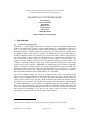
SENSECAM V2.3B USER GUIDE
Steve Hodges
James Srinivasan
Alex Butler
Matthew Lee
Gavin Smyth
James Scott
Alban Rrustemi
Microsoft Research Cambridge
1. Introduction
1.1. Overview of v2 SenseCam
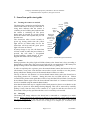
SenseCam is a small digital camera that is designed to take photographs automatically
without user intervention. Unlike a regular digital camera or a cameraphone, it does not
have a view finder or a display that can be used to frame photos. Instead, it is fitted with a
wide-angle (fish-eye) lens that maximises its field-of-view. This in turn means that nearly
everything in front of the camera is captured. In addition to the camera functionality, a
number of different sensors are built into the v2 SenseCam. These include a light intensity
and colour sensor, a passive infrared (body heat) detector, a temperature sensor and a triaxis accelerometer. These sensors are monitored by the camera‟s microcontroller, and
changes in sensor readings can be used to automatically trigger the camera shutter. For
example, a significant change in light level, or the detection of body heat in front of the
camera can be used as triggers. Additionally, an internal timer may be used to trigger the
shutter, for example causing an image to be captured automatically every 30 seconds. The
maximum possible rate is an average of around one photo every 5 seconds, i.e. 12 photos
per minute. SenseCam also has a manual trigger button that lets the wearer take pictures in
the more traditional fashion, albeit without the use of a viewfinder.
The VGA resolution images are stored as compressed .JPG files on an internal flash
memory card (currently 1Gbyte cards are fitted). The typical image size (around 30k bytes)
allows for over 30 thousand images to be stored in the camera. In addition to image data, the
memory card is used to store a log file, which records the sensor data each time the sensors
are read (every few seconds). The log file also records the reason for taking each photograph
(e.g. manual shutter press, timed capture or significant change in sensor readings). The log
file is in a comma-separated value format suitable for importing directly into Microsoft
Excel1 and many other data manipulation tools. The SenseCam has a built-in real time clock
that ensures the timestamps of all files on the storage card are accurate. Timestamp
information is also recorded in the log file along with each entry.
1
Note that Excel 2003 has a 32k row limit which can be exceeded by large sensor files.
SenseCam v2.3 User Guide
Page 1 of 31
10/03/2009
Company confidential proprietary information. Do not distribute.
© 2009 Microsoft Corporation, all rights reserved.
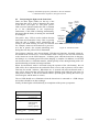
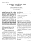
Figure 1: Example images captured by SenseCam.
In trials to date, users have worn the camera on a cord around their neck, although it would
be possible to use a clip for pockets or belts. One advantage of using a neck-cord to wear the
camera is that it is reasonably stable when being worn, and it is also reasonably high-up
(closer to the wearer‟s eyeline) which generates more compelling images. The camera
contains a rechargeable lithium-ion battery that lets it run for a complete day on a full
charge. It takes around three hours to recharge using a mains power adaptor or a PC USB
connection. There is an on-off button on the camera, which can be used to save the battery
and prevent any sensor data logging/photograph capture. LEDs and an internal sounder are
used to give the wearer feedback.
The high speed USB interface used for recharging is also used to transfer the image and
sensor data to a PC. An expansion connector on the bottom of the camera may potentially be
used to connect a number of different add-on devices, such as an external battery, an
additional camera, wireless communications or additional sensors. The expansion connector
can also be used to update the firmware that controls the operation of the SenseCam, for
example to add new features or integrate add-on devices. A future enhancement will include
a microphone and audio recording and audio-level triggering circuitry (so that photos can be
taken automatically in response to noises).
1.2. This document
This document is a user guide for the v2.3b SenseCam. It describes the operation of the
camera and of the associated PC software that is used to display SenseCam image data. It
also describes in some detail various options available to the user of a SenseCam to alter the
default configuration of the unit using a PC and a USB cable. Unless specifically stated, the
descriptions herein are based on the most recent firmware build.
For a very quick overview of the v2.3b SenseCam and its operation, please refer to the
quick-start guide in Section 2.
1.3. Microsoft Limited Licence Agreement
Please note the terms and conditions of the Microsoft Limited Licence Agreement
associated with the use of the SenseCam hardware and software. This agreement has to be
signed by all SenseCam recipients external to Microsoft before they are supplied with the
SenseCam hardware and MSRC Viewer/Importer Software.
SenseCam v2.3 User Guide
Page 2 of 31
10/03/2009
Company confidential proprietary information. Do not distribute.
© 2009 Microsoft Corporation, all rights reserved.
2. SenseCam quick-start guide
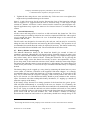
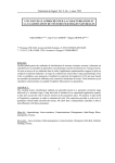
2.1. Turning the camera on and off
The SenseCam is turned on and off using the
small round button on the top of the unit. A
rising tones indicates that the camera is
switching on and a falling tone indicates that
the camera is switching off. The power
button must be pressed for several seconds
before the camera will respond and you will
hear the tone.
The SenseCam takes several seconds to
power up, during which time the yellow
light will be on. When ready for use, the
SenseCam will beep and the green power
light will come on instead.
If battery charge is very low, the SenseCam
will not switch on when the power button is
pressed, but will make a low-pitched
buzzing/warbling sound instead. If this
happens the camera must be charged up.
Green
„power‟
On/off
light
button
Yellow
„busy‟
light
Red/green
„charging‟
and „do-notdisturb‟ light
light
Do-notdisturb
button
Manual
shutter
Figure 2: SenseCam lights and buttons
2.2. In use
During operation, the yellow light will blink whenever the SenseCam is busy recording a
photograph or sensor data. The green power light will be on continuously if the battery has
plenty of charge and it will blink occasionally if the battery is getting low.
In order to explicitly take a picture, press the manual shutter button (the bottom of the two
side buttons) at any time. Note that the camera takes several seconds to save the picture,
during which time further presses of the manual shutter will have no effect.
The top of the two side buttons is a do-not-disturb button which causes the SenseCam to
stop taking pictures for 7 minutes. During this time, the red LED will be on. Fifteen
seconds before pictures start again there will be a beep and the LED will flash. Pressing the
do-not-disturb button again resets the do-not-disturb timer back to 7 minutes. Pictures can
also be re-enabled using the manual shutter button.
Note that the SenseCam may be supplied with a black protective plastic cover fitted over the
glass lens, to protect it from damage during shipping. This can be removed by carefully
pulling it away from the body of the camera (it is a push fit and does not need to be
unscrewed). In day-to-day operation the lens cover is not likely to be needed.
2.3. Charging
The battery will charge whenever the SenseCam is connected to a computer or a mains
charger. Before connecting the camera to a charger or to a computer, please make sure that
the unit is switched on. If the unit will not switch on due to a flat battery (low-pitched
buzzing/warbling sound), please connect it to a charger or a computer for 15 minutes, then
SenseCam v2.3 User Guide
Page 3 of 31
10/03/2009
Company confidential proprietary information. Do not distribute.
© 2009 Microsoft Corporation, all rights reserved.
disconnect it, turn it on and reconnect as usual. When plugged in, a flashing green light
indicates that the battery is charging; solid green indicates fully charged.
It takes around 3 hours to charge the battery from flat. It is not possible to „over-charge‟ the
battery, and it is safe to leave plugged in overnight. It is also OK to „top up‟ the battery by
re-charging it before it is fully exhausted. A fully-charged battery should allow up to 36
hours of operation although this varies with frequency of image capture and may be as low
as 12 hours.
Connecting it to a PC or charger while it is switched off may result in the unit appearing not
to respond as expected (for example, the charging light may not come on). If this happens, it
is recommended that you disconnect the camera, switch it on, and then re-connect.
2.4. Transferring data
Photographs and sensor data may be transferred from the camera to a computer using the
USB cable supplied. No special USB drivers are required; the camera will simply appear as
an external flash drive under Windows. It is possible to browse SenseCam images (which
will be recorded as a sequence of .JPG image files in various folders on the camera) directly
from Windows, and to load the sensor data into Microsoft Excel. However, it is
recommended to use the SenseCam Image Viewer software supplied to move the images
from the SenseCam onto the PC because this software performs additional operations, such
as tagging files and synchronising the SenseCam real-time clock. Transferring the images
may take many minutes; a status bar indicates progress.
2.5. SenseCam Image Viewer software
One way of copying and viewing SenseCam images and sensor data is to use the SenseCam
Image Viewer software supplied with the camera. This may be installed directly from the
camera – simply connect it to the PC via USB, and run setup.exe from the folder within the
\PCVIEWER folder. The software will also install the .NET framework 2.0 if required.
During installation select „Advanced Operation‟ if you want to be able to view sensor data.
Following installation, whenever the camera is subsequently connected to the PC the
„Import photos from SenseCam using SenseCam Import‟ option should be selected. Section
3 gives a lot more detail about the installation, use and configuration of the MSRC viewer
software.
Note that currently the software requires that the user is a local administrator of the machine
to run properly.
2.6. General
The SenseCam is a research prototype. Please bear in mind that it is not as robust as a
typical commercial product. It is not particularly waterproof so please be careful in the rain.
Documentation is supplied on the camera itself, in the \DOCS folder.
Please note the terms and conditions of the Limited Licence Agreement associated with the
use of the SenseCam hardware and software before you attempt to install or use the PC
software. This agreement has to be signed by all SenseCam recipients external to Microsoft
before they are supplied with the SenseCam hardware and MSRC Viewer/Importer
Software.
SenseCam v2.3 User Guide
Page 4 of 31
10/03/2009
Company confidential proprietary information. Do not distribute.
© 2009 Microsoft Corporation, all rights reserved.
3. MSRC SenseCam PC viewer software
The SenseCam is supplied with PC software that has been developed by Microsoft Research
Cambridge. This software comprises two main applications: (1) the SenseCam Image
Importer, which can be used to transfer images and sensor data from the SenseCam to the
PC; and (2) the SenseCam Image Viewer, which can be used to view previously imported
data. The Image Viewer is started automatically following the import operation to allow the
user to review the image and sensor data that has just been transferred.
Even if you do not intend to use the SenseCam Image Viewer, it is highly recommended
that you do use the SenseCam Image Importer to transfer data from the SenseCam to the
PC. If you simply move files from the SenseCam to the PC using Windows Explorer (or a
similar application) you will not enjoy several benefits of using the Image Importer, such as
automatic synchronisation of the SenseCam real-time clock with the PC, image tagging with
EXIF data, or automatic image rotation.
Please note the terms and conditions of the Limited Licence Agreement associated with the
use of the SenseCam hardware and software before you attempt to install or use the PC
software.
3.1. Installing the MSRC software
The SenseCam Image Importer and Viewer software is supplied on the camera. Using
Windows Explorer, browse to the „\PCVIEWER‟ folder on the camera‟s flash disk. Inside
this folder there is another folder with a numeric name, such as „1.11.0‟. (The numeric name
indicates the version number of the SenseCam Image Importer supplied on the camera.
Later versions may be available from Microsoft Research.) Inside this folder, there is an
application called „setup.exe‟. Install the software by double-clicking on „setup.exe‟ to run
it.
The SenseCam Image Viewer requires the .NET framework 2.0; the application installer
will first install the .NET framework if necessary. When this is complete, the application
itself will install. Installation is most straightforward if you accept the default options; in
this case you only need to click on the „Next‟ button at the bottom right of each of the four
installation dialog boxes.
In the second dialog box during installation there is an option to choose "Basic" or
"Advanced" operation. The “Basic” option exposes all the basic features of the viewer for
editing, bookmarking, and viewing the images. The “Advanced” option is a bit of a
misnomer – it simply exposes a number of miscellaneous experimental functions that are
not yet fully refined. This extra functionality is displayed as a toolbar at the top of the
application window. (You can change this setting retrospectively if necessary, see Section
3.6.) Note that if you want to be able to view sensor data, you should select „Advanced
operation‟.
SenseCam v2.3 User Guide
Page 5 of 31
10/03/2009
Company confidential proprietary information. Do not distribute.
© 2009 Microsoft Corporation, all rights reserved.
Figure 3: When installing the SenseCam Image Viewer software it‟s easiest to use all the
default options and just click the „Next‟ button on each of the dialog boxes.
When the software installation is complete there will be
two new icons on the desktop. The „SenseCam Image
Viewer‟ icon can be used to run the Image Viewer
application, whilst the „SenseCam Images‟ icon is a
shortcut to the folder where the imported image
sequences are stored. It is also possible to use the
Windows Start menu instead of the desktop icons (select
„Start‟ then „All Programs‟ then „SenseCam‟ followed
by „SenseCam Image Viewer‟ or „SenseCam Images‟).
Figure 4: After installation there will be two
new desktop icons.
3.2. Using the SenseCam Image Importer
When you attach the SenseCam to a PC, Windows will bring up a dialog box asking you
what you want to do with the associated files. As long as the SenseCam Image Viewer
software has been installed, one of the options will be „Import photos from SenseCam using
SenseCam Import‟. Select this option whenever you dock the SenseCam.
SenseCam v2.3 User Guide
Page 6 of 31
10/03/2009
Company confidential proprietary information. Do not distribute.
© 2009 Microsoft Corporation, all rights reserved.
It is possible to tell Windows to automatically use SenseCam Import every time a device
containing images is connected to your PC (check the „Always do the selected action‟ box).
However, this is not recommended if you are likely to plug other devices with images (such
as a regular digital camera) into the PC from time to time because these will also cause the
SenseCam Image Importer to run which is probably not desired behaviour. Also note that an
„empty‟ SenseCam will not result in the SenseCam Import option being displayed.
Prior to importing the images, the SenseCam Image Importer will show a dialog requesting
the user to enter a name for the set of images that are about to be imported. Though optional,
specifying a name here helps to keep the SenseCam images organised. When new images
are imported from the SenseCam, the SenseCam Image Importer creates a new folder on the
PC‟s local storage to store them in. This folder is named with the time and date of import
(which is not directly related to the times that the images and sensor data were collected)
and the name entered by the user into the dialog prior to importing. An example folder name
is “10-February-2006 10-40-43 # Visiting London”. An example without the album name
specified is “10-February-2006 10-40-43 #”.
The date-based folder names that have been created by default can be manually edited
afterwards using Windows Explorer. The viewer application assumes that folder names will
start in the default way in order to sort them chronologically. It is strongly advised to avoid
changing the part of the folder name before the „#‟ character. However, it is fine to change
the folder name after the „#‟ character by either appending text after the „#‟ character to
name the set of images or changing the text if a name was already specified during the
importing of images. Anything after the „#‟ will be ignored by the viewer application.
The easiest way to change the image folder names is to use the shortcut to „SenseCam
Images‟ which was created on the desktop/in the Start menu when the software was
installed. Selecting this shortcut starts up a new Explorer window with all the imported
folders displayed. By default, the location of this is “C:\Documents and
Settings\<username>\Local Settings\Application Data” folder. This location may be
changed by editing the Windows registry (see Section 3.7). If you want the viewer
application to use SenseCam (or other) images already stored on your machine, edit the
registry string to point to the directory containing image folders or copy/move those
directories into the image root directory.
3.3. Using the basic features of the SenseCam Image Viewer
When the SenseCam Import is complete, the SenseCam Image Viewer application will
automatically start and load in the new images. If the SenseCam Image Viewer is started via
the Windows Start menu (or via the shortcut on the desktop), it will present a list of all the
folders imported to date, and whichever is selected will be displayed in the viewer.
Having loaded up a set of images, the sequence can be replayed slowly using the „Play‟
button (labelled „>‟) or more quickly using the „Fast Forward‟ button (labelled „>>‟). As the
sequence plays, the slider underneath the image progresses from left to right. Playback can
be paused at any point with the „Pause‟ button. The mouse can be used to manually drag the
slider to a particular position and have playback continue from that point. It is also possible
to play the image sequence in reverse using the „Back‟ and „FastBack‟ buttons. Any images
in a sequence which are unwanted may be removed by using the „Delete‟ button: this does
not actually delete the files, but merely records (in a configuration file) that they are not to
be used as part of the playback sequence.
SenseCam v2.3 User Guide
Page 7 of 31
10/03/2009
Company confidential proprietary information. Do not distribute.
© 2009 Microsoft Corporation, all rights reserved.
The wide-angle (or „fish-eye‟) lens fitted to SenseCam introduces distortion to the image –
lines which are straight in the real world will tend to be captured as curved lines. Clicking
on the „Undistort‟ button to the left of the „FastBack‟ button puts the Image Viewer into a
mode where it approximately corrects for this distortion. Clicking on the same button a
second time will restore the image to the original form. A side-effect of using the
undistortion option is a small black band at the top and bottom of the images.
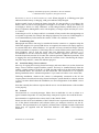
The viewer also has to modes: Advanced Mode and Simple Mode. Advanced Mode (Error!
Reference source not found.) reveals the editing features of the viewer such as image
deletion, bookmark creation, image (un)distortion and the list of bookmarks. Simple Mode
(Error! Reference source not found.) hides all the editing features of the viewer and
simply displays the image and playback controls. Simple Mode is useful for viewing the
images without the distractions and potential dangers of accidental deletion of images. Upon
start-up, the viewer application starts in Advanced Mode. To enter Simple Mode, click the
“Simple Mode” button located in the lower left-hand corner of the viewing pane. Once in
Simple Mode, clicking the “Advanced Mode” button switches the application back to
Advanced
Mode.
Figure 5: The SenseCam viewer application, allowing playback and review of SenseCam images.
SenseCam v2.3 User Guide
Page 8 of 31
10/03/2009
Company confidential proprietary information. Do not distribute.
© 2009 Microsoft Corporation, all rights reserved.
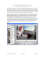
Figure 6: The SenseCam viewer application in Simple Mode which hides editing functions.
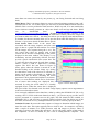
With long sequences of images, it can be useful to associate „Bookmarks‟ with certain
images. A bookmark is created by pausing playback on the image in question, and then
clicking on the „Add‟ button at the bottom left of the screen. The bookmark will appear as a
thumbnail on the left-hand side of the display; by clicking on the default the name of
„<bookmark>‟, a more meaningful name can be assigned. Once bookmark(s) have been
created, it is possible to return to the image associated with the bookmark simply by clicking
on the bookmark. The bookmark text is also shown as overlay text (Error! Reference
source not found.) on the images in the viewer. This overlay feature can be turned off by
pressing the “Hide Text” button (located in the lower-right corner) found in “Simple mode”.
Bookmarks can also be associated with a series of images. To create a bookmark that spans
a range of images, advance the viewer to the image for which you want the bookmark to
start. Click the “Start Bookmark” button (located under the playback controls). Then
advance the viewer to the image where you want the bookmark to end. Click the “End
Bookmark” button. A new window titled “Create a bookmark” will appear showing you a
preview of the images you selected to be bookmarked. If you selected to bookmark more
than 12 consecutive images, this window will select 12 representative images from the range
and display them. The image in the top left corner is always the first image in the range you
selected. The image in the bottom right corner is always the last image in the range you
selected. You can type in the text field the bookmark text. Press the “Make Bookmark”
button. The “Create a bookmark” window will close, and the bookmark will be added to the
range of images. The bookmark will show up in the bookmark list in the left hand side and
the bookmark text will be overlaid on the image accordingly.The list of bookmarks can be
SenseCam v2.3 User Guide
Page 9 of 31
10/03/2009
Company confidential proprietary information. Do not distribute.
© 2009 Microsoft Corporation, all rights reserved.
sorted by bookmark name, or by the position of the bookmark within the image sequence
(i.e. by time). Bookmarks can be permanently deleted using the „Remove‟ button. The entire
list of bookmarks can be temporarily hidden with the „Hide Bookmarks‟ button at the top
left of the display.
Figure 7: Bookmarks are shown as overlay text on the image.
3.4. ‘Advanced’ operation of the SenseCam Image Viewer
If the SenseCam Image Viewer software is installed with „Advanced Operation‟ selected,
then there will be several additional options available at the top of the window. These
options are not available in the Basic installation.
Overlay: Displays an analogue clock face to the right of the image sequence indicating at
what time of day the image displayed was originally taken. The hands on the clock face spin
around as the movie is played. To enable the analogue display overlay, single click on the
option. To remove the display, click on the option again.
Preview: Opens the Windows picture preview window on the current image, thereby
providing access to printing and editing. Changing the currently selected image while the
preview window is still displayed is not recommended.
Load Slave: Allows additional SenseCam image sequences to be loaded in and displayed at
the same time as the main sequence. This is useful if you have sequences that were recorded
at the same time – for example if two or more people were wearing SenseCams at an event.
For each additional image sequence that is loaded in, a new viewing window is created.
Playback will result in the individual image sequences playing in their respective windows
in synchronisation with each other. This is also useful for playing back sequences where
SenseCam v2.3 User Guide
Page 10 of 31
10/03/2009
Company confidential proprietary information. Do not distribute.
© 2009 Microsoft Corporation, all rights reserved.
more than one camera was worn by one person (e.g. one facing forwards and one facing
back.)
Make Movie: This is a prototype feature to convert a SenseCam image sequence into a selfcontained movie file. To use this option you first need to install Windows Media Encoder
(WME). This is used to perform the final encode to .WMV step and, if it's not installed the
viewer software currently generates an “object not found” error message and aborts. WME
can
be
downloaded
from
http://www.microsoft.com/windows/
windowsmedia/forpros/encoder/default.mspx. "Windows Media Encoder 9 Series" is the
only version used in testing. Before clicking the Make Movie button, choose the image run
you want to make into a movie – the dialog box allows you to specify start and end frames
by number, but doesn't currently allow you to preview them while the dialog box is open.
Section 3.6 gives more details on Make Movie options.
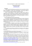
Load Sensor Data: Loads in the sensor data
associated with the image sequence and plots each
type of data as a graph with the timeline over which
all the images were captured along the x axis. The
raw sensor data values are plotted, with a black
vertical line at the time corresponding to the picture
displayed in the main window. This display is very
rudimentary and not particularly efficient, but does
provide a quick visualisation of the sensor data. The
„CAM‟ plot shows the reason for each photo capture,
where 1 = timer, 2 = PIR, 4 = light level, 8 = manual
capture. The „RST‟ line (not shown in Figure 8)
shows pulses where the camera is turned on or off.
Double-clicking on the window brings up a dialog
box that allows each of the values to be selected (i.e.
shown on the graph) or deselected (i.e. hidden). By
default they are all shown, including the texton
parameters Chi Sq, Squared and Alpha D (see below).
There is a zoom function which can be used when a
lot of sensor data readings are displayed, this is
activated by using the scroll wheel on a suitably- Figure 8: Sensor data display
equipped mouse. When the sensor data is displayed,
the speed of the "fast forward" and “fast back” image display options will be degraded due
to the sensor data redraw times.
You can supply additional sensor data lines, either by editing the SENSOR.CSV file, or by
creating a new .CSV file in the same format (see later) – you can use any tag you like, and it
will be presented as a separate trace on the graph. This file should be time ordered, as
SENSOR.CSV is, and must have a correctly formed real-time clock line before any of the
new data, and at least on every midnight transition (in order to correctly specify the date).
Calculate Textons: Processes the entire sequence of images to determine which images are
most like each other. This option typically takes a while to run – for example it will likely
take a couple of minutes on a 3GHz processor with 100 images to process. There is
currently no progress bar during this operation – the UI will simply appear to hang until it
has completed – so once it‟s started, it‟s just a case of waiting until it‟s complete… The
SenseCam v2.3 User Guide
Page 11 of 31
10/03/2009
Company confidential proprietary information. Do not distribute.
© 2009 Microsoft Corporation, all rights reserved.
image similarity data that is generated is cached (in the image.dat file) so that it is available
subsequently without requiring re-generation. When textons have been generated, a number
of marks appear under the image playback progress bar – these indicate points in the image
sequence where the scene appears to change significantly – and they therefore effectively
split the image sequence into segments of related images. The sensitivity of this
segmentation is adjustable using the slider to the right of the „Calculate Textons‟ option.
3.5. Sequence of operations when the SenseCam Image Importer runs
The Image Importer performs the following sequence of actions:
1. Saves a copy of the current PC time for later use (step 6 below).
2. Creates a new directory on the PC into which to store everything from the
SenseCam.
3. Iterates over every file on the SenseCam in any directory under \DATA:
a. Copies JPG files to the PC. Images may be rotated if necessary. EXIF
timestamps and TIFF manufacturer ("Microsoft") and model ("SenseCam")
headers are added as files are copied across
b. Copies the one and only log (SENSOR.CSV) file to the PC
4. Deletes everything under \DATA and including the DATA directory itself. (This is
extremely time consuming despite the USB 2.0 connection. This is not due to any
aspect of SenseCam firmware, but is because of the nature of the FAT file system
on flash memory devices.)
5. Deletes any existing \SYSTEM\TIME.* and writes a new \SYSTEM\TIME.CSV
with the time recorded in step 1 above. In this way, TIME.CSV will contain the
time at which the SenseCam was connected to the PC (to a reasonable
approximation).
6. Finally, invokes the viewer (or other application) on the copied directory.
3.6. SenseCam Viewer configuration file
Several aspects of the SenseCam Viewer operation may be controlled by altering the XML
format configuration file in the install directory (by default <program files>\Microsoft
Research Ltd\SenseCam). Do be careful when editing this file: if the viewer application
cannot read it, it will not start. Note that the file is only read when the program starts, so
changing it while the viewer is running will have no effect until you restart.
Viewer.SlowInterval/Viewer.FastInterval:
There is some limited playback speed control via the two lines:
<add key="Viewer.SlowInterval" value="500" />
SenseCam v2.3 User Guide
Page 12 of 31
10/03/2009
Company confidential proprietary information. Do not distribute.
© 2009 Microsoft Corporation, all rights reserved.
<add key="Viewer.FastInterval" value="40" />
These give the target time delay between images in milliseconds for "slow" and "fast"
forward/backward buttons. Note that the fastest speed will be whatever your PC can
manage, so it can max out before getting down to your chosen speed.
Viewer.Toolstrip.Visible:
The advanced options are displayed in the viewer if the Viewer.Toolstrip.Visible key
is set to True:
<add key="Viewer. Toolstrip.Visible " value="True" />
When set to False, the basic mode of the viewer will be in operation.
Viewer.Left.Visible:
Viewer.Left.Visible shows or hides the Bookmark window on program startup.
Viewer.KeepAvi:
The „Make Movie‟ option mentioned in Section 3.4 above first assembles the chosen
run of images into a large uncompressed .AVI file, then runs WME to convert that
into a much smaller .WMV file, deleting the .AVI file after. WME is typically used
with a "profile" – a set of encoder parameters such as bit rate and image size: a few
SenseCam specific profiles are provided (the ones starting with "SC"), but they have
not been tuned at all. To allow experimentation with other parameters (and creation
of better profiles), you can disable the deletion of the .AVI file by setting
Viewer.KeepAvi to “True” and then run WME directly on that (to be found in your
TEMP directory, with a name like "tmpABCD.tmp.avi"). The WME installation pack
includes a tool to create profiles, which you can then copy into the Profiles
subdirectory and have appear in the make movie dialog box. (If you call them "SC
something" they'll appear in the same place in the list as the existing ones, making
them easier to locate.) If you use WME directly, you can also add additional channels
– such as audio. You could also use Windows Movie Maker on the .AVI file to glue
together several segments and add various transition effects.
Figure 9: MSRC SenseCam Image Viewer configuration file options.
3.7. SenseCam Viewer registry settings
As well as the configuration file described above, some settings are specified via the registry
(typically ones that affect more than just the viewer).
The application that is invoked by the SenseCam Image Importer can be changed by
specifying an executable in HKEY_CURRENT_USER\Software\Microsoft Research
Ltd\SenseCam\Viewer, ideally using the full path (although that is not necessary in some
SenseCam v2.3 User Guide
Page 13 of 31
10/03/2009
Company confidential proprietary information. Do not distribute.
© 2009 Microsoft Corporation, all rights reserved.
cases). The executable is passed the destination directory as a command line argument. As
an example, if you specify “explorer.exe” in that registry key, Windows Explorer will be
opened on the target directory via the command line “explorer.exe "<full path to copied
directory>"”. If the registry entry is omitted, the default is the MSRC viewer.
The
registry
key
HKEY_CURRENT_USER\Software\Microsoft
Research
Ltd\SenseCam\ImageRoot is used to specify the location where SenseCam data is
imported to, and where the SenseCam Image Viewer expects to find image sequences. By
default it is set to “C:\Documents and Settings\<username>\Local Settings\Application
Data”.
The SenseCam hardware produces upside-down (i.e. 180° rotated) images natively. The
latest SenseCam firmware can be configured to rotate all images by 180° inside the camera,
so that they appear right-side-up. By default, the SenseCam Image Importer will check the
SenseCam configuration (recorded in the SENSOR.CSV file) and will rotate images during
import if necessary (i.e. if this was not done by the SenseCam firmware). This behaviour of
the Image Importer can be manually overridden (i.e. the importer will always rotate the
images)
by
creating
registry
DWORD
ImageRotate
in
HKEY_CURRENT_USER\Software\Microsoft
Research
Ltd\SenseCam.
Setting
HKEY_CURRENT_USER\Software\Microsoft Research Ltd\SenseCam\ ImageRotate
to 0 means no rotation, 1 means importer should rotate.
3.8. SenseCamFileCopier
One of the files in the install directory of the SenseCam Image Viewer (C:\Program
Files\Microsoft Research Ltd\SenseCam Import by default) is SenseCamFileCopier.exe.
This executable is responsible for the file import process described in Section 3.2. During
the course of data import to the PC, SenseCamFileCopier.exe is run from within the root
directory of the SenseCam (e.g., E:\).
SenseCamFileCopier.exe can also be used manually to (re-)import a previously backed up
SenseCam file system into the standard viewing location. For example, if a SenseCam file
system has been copied to C:\SC_Backup (in which case C:\SC_Backup will contain
\DATA and \SYSTEM directories), then the data in C:\SC_Backup may be imported
manually by opening a DOS command prompt in C:\SC_Backup and running
SenseCamImageCopier.exe from that location.
Note that the executable takes a single optional command line argument, /autoplay – if this
is set (as will be the case for a normal, automatic SenseCam import), the files on the source
will be deleted; if not, the source is untouched.
SenseCam v2.3 User Guide
Page 14 of 31
10/03/2009
Company confidential proprietary information. Do not distribute.
© 2009 Microsoft Corporation, all rights reserved.
4. SenseCam operation in more detail
4.1. SenseCam configuration
Various aspects of SenseCam operation are configurable at the time of camera production.2
These configuration options are stored in non-volatile EEPROM memory in the SenseCam
microcontroller. Section 5.4 describes how the BOOT.BAT file may be used to override
and/or change the different configuration options.
4.2. Sensor-based image capture algorithm
The SenseCam runs a very simple algorithm that determines when a new image should be
captured, based on some of the sensor values and the passage of time. The basic algorithm is
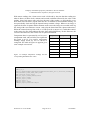
listed in Figure 10. Note that each of the individual capture triggers can be overridden using
the BOOT.BAT file (see Section 5.4). The parameter of TakePicture() is logged as the
reason code in the SENSOR.CSV file.
while (true)
{
if (do not disturb mode) continue;
if (continuous triggering enabled)
TakePicture(‘C’);
if (manual triggering enabled)
if (manual shutter button pressed)
TakePicture(‘M’);
if (sensor triggering enabled)
{
if (significant change in white light level)
if (not taking a manual picture anyway)
TakePicture(‘L’);
if (SenseCam is stationary && PIR has changed state)
if (not taking a manual picture anyway)
TakePicture(‘P’);
}
if (timer triggering enabled)
if (timed out)
if (not taking a manual picture anyway)
TakePicture(‘T’);
}
Figure 10: Basic SenseCam image capture algorithm.
2
Technically these are actually set at the time that the camera is commissioned at MSRC, rather than
at time of assembly of the electronics.
SenseCam v2.3 User Guide
Page 15 of 31
10/03/2009
Company confidential proprietary information. Do not distribute.
© 2009 Microsoft Corporation, all rights reserved.
4.3. Interpreting the lights on the SenseCam
There are three lights (LEDs) on the top of the
SenseCam that can be used to determine the status
of the device (see Figure 11). The green „power‟
LED is used to indicate whether the unit is switched
on or not (illuminated or not respectively).
Furthermore, if this LED is blinking intermittently,
this means that the battery is running low and should
be recharged.
Green
Yellow
„power‟
„busy‟
light
light
On/off
button
Red/green
„charging‟
The yellow „busy‟ LED is used to indicate that the
and „doSenseCam microcontroller is busy. This is typically
not-disturb‟
when the unit is reading sensor information and
light kind of internal operation.
storing it into flash memory, but may also indicate some other
For example, whenever the SenseCam is powered
Figure 11: SenseCam LEDs.
on it has to spend a few seconds initialising and
during this time the yellow LED is illuminated.
The red/green „charging‟ and „do-not-disturb‟ LED has two functions. Normally (when donot-disturb mode is not active), it will illuminate when a charger or PC has been connected
to the SenseCam via the USB connector. It flashes green when the SenseCam is charging,
and changes to a constant green LED when charging is complete. In addition, it will flash
red whenever there is a USB data transfer, which typically occurs during docking with a PC
and downloading of SenseCam images and data.
When „do-not-disturb‟ mode is activated (using the topmost of the side buttons), the red
LED will be lit to indicate that do-not-disturb mode is active and no pictures will be taken.
This lasts for around 7 minutes. When there are 15 seconds left in do-not-disturb mode, a
tone will be played and the red LED will continue flashing until either the time runs out
(and pictures restart), or the do-not-disturb button is pressed again (causing the LED to go
solid red again, and the timer to restart).
The red LED should never illuminate when the SenseCam is connected to a USB charger
unit as there should be no data exchange.
Finally, all three lights will flash briefly on completion of the power up sequence.
Green „power‟ LED
LED status
Meaning
Off
Switched off
Solid green
Switched on
and operating
with good
battery capacity
Intermittently
blinking green
Powered up and
operating with
SenseCam v2.3 User Guide
Page 16 of 31
10/03/2009
Company confidential proprietary information. Do not distribute.
© 2009 Microsoft Corporation, all rights reserved.
poor battery
capacity
Figure 12: Summary of the meaning of the
green „power‟ and red/green „charging‟
LEDs.
4.4. Interpreting the sounds from
the SenseCam
There are five main audio cues utilised
by a SenseCam to indicate specific
actions either underway or completed:
Red/green „charging‟ and „do not disturb‟ LED
LED status
Meaning
Off
No charger or PC connected, donot-disturb mode off
Solid green
Either a charger or a PC is
connected via USB & battery is
fully charged
Blinking green
Either a charger or a PC is
connected via USB & battery is
being charged
Intermittent red
A PC is connected via USB, and
data is currently being exchanged
between the PC and the SenseCam
Solid red
Do-not-disturb mode active
Rising cadence: The SenseCam is Blinking red
switching on and will soon be ready for
operation. It is normally followed by a
final “beep” when the unit is fully operational.
Do-not-disturb mode ending
shortly
Falling cadence: The SenseCam is switching off.
Beep: A manually triggered photo is being taken; it is sounded at the exact time that the
image is taken. A similar beep also occurs when the camera is first ready for use after it has
been switched on; in this case there is no associated photo capture.
Low warble: The battery level in the SenseCam is insufficient for the unit to switch on; the
battery must be charged before the unit can be switched on.
2-tone low-high beep: Do-not-disturb mode will end shortly
4.5. Lens
The lens fitted to the SenseCam is a V-4301.9-2.0FT-IRC from Marshall Electronics. This is
a 119º (diagonal) wide-angle lens with an IR filter in an M12x0.5mm form factor. In theory
this can be replaced by a different specification M12x0.5mm lens. To do this:
1. Loosen the small set (grub) screw which locks it in place using a suitably-sized allen
key (0.9mm between flats).
2. Remove the existing lens by carefully unscrewing it. Be careful not to let the image
sensor get dirty while it is exposed.
3. Fit the replacement lens, being careful not to cross-thread it (this would permanently
damage the plastic thread in the SenseCam case) and being careful not to screw it in so
far that it touches the image sensor (this would permanently damage the image sensor).
4. Manually focus the lens by iteratively taking pictures with the SenseCam, viewing them
on the PC and adjusting how far the lens is screwed in.
SenseCam v2.3 User Guide
Page 17 of 31
10/03/2009
Company confidential proprietary information. Do not distribute.
© 2009 Microsoft Corporation, all rights reserved.
5. Tighten the lens using the set screw and allen key. Take care not to over-tighten; this
might result in permanent damage to the camera.
Steps 2, 5 and 6 above may also be used to fine-tune the focus of the SenseCam with the
lens as supplied. It is suggested that the unit be focussed using a visual target of high
contrast at a distance of between 1 and 2 metres from the camera for general-purpose use.
Special applications may require the camera to be focussed closer to or further from the
camera.
4.6. Internal flash memory
All the sensor and image data is stored on an SD card inside the SenseCam. The VGA
resolution images recorded by SenseCam are stored as compressed JPEG files with a typical
size of around 30k bytes. This allows for over 30 thousand images to be stored on the
standard 1GB SD card.
The SD card is not designed to be removed by the end user, and can only be accessed by
taking the back off the SenseCam and removing the PCB assembly. This operation is not
recommended, but would allow the card to be replaced if necessary. The SenseCam has only
been tested with 1GB and 2GB SD cards. The new 4GB SD cards will not work.
4.7. Battery lifetime and charging
The 980mAh lithium-ion battery in the SenseCam should give around 36 hours of
continuous operation, although this will depend on how frequently images are taken since
the VGA camera module and SD card are quite power-hungry. Very frequent image capture
may reduce battery life to around 12 hours. Turning the SenseCam „off‟ by pressing the
power button simply causes the SenseCam circuitry to enter a non-operational, very low
power sleep mode. In this mode the real-time clock, which is needed to time-stamp images
and sensor data when the camera is next switched on, is left running. The camera draws just
152uA in low power mode, so it will run for up to 9 months before the battery is completely
drained.
The battery charge can be „topped up‟ at any time by connecting the SenseCam to a power
source (either a USB host, USB hub or the supplied USB mains charger). It is strongly
recommended that you switch the SenseCam „on‟ before connecting it,3 because this is the
only way to ensure that the red/green „charging‟ LED correctly reflects the state of the
device (see Section 4.3). The lithium-ion battery should be pretty immune to the „memory
effect‟ associated with other rechargeable battery chemistries, so „topping up‟ should not
affect the capacity of the battery.
If the battery charge becomes low during operation of the SenseCam, the green „power‟
LED will flash intermittently as a warning to the user (see Section 4.3). Eventually, the
charge will become so low that the SenseCam microcontroller will automatically switch the
device off. Trying to switch the unit back on in this condition will result in a low pitched
warble (see Section 4.4 above). Obviously in this case the SenseCam must be connected to a
power source with the unit still switched „off‟. After around 15 minutes of charging,
disconnect the SenseCam and switch it on (the battery should have enough charge to do
3
Even though the SenseCam will promptly switch itself off as soon as the connection is detected.
SenseCam v2.3 User Guide
Page 18 of 31
10/03/2009
Company confidential proprietary information. Do not distribute.
© 2009 Microsoft Corporation, all rights reserved.
this), then resume charging if required (and this time the red/green „charging‟ LED will be
operational.
If the SenseCam is run until it powers itself off, and then left for several weeks without recharging, the real-time clock may be reset to 0:00:00 on 1/1/2000. All images taken
subsequently will have the correct relative timing (assuming a further reset to the real-time
clock has not occurred). The real-time clock can be set to the correct time automatically
using the MSRC SenseCam Image Importer or manually using the BOOT.BAT or
TIME.CSV files (see Section 5).
With the default SenseCam configuration (fast charge enabled, see Section 4.8 below), the
battery will take around 3 hours to recharge from being completely flat. The SenseCam will
charge at the same rate whether connected to a USB mains adapter or a USB host or hub.
4.8. Adjusting the charge current
The maximum amount of current drawn by the SenseCam when charging can be set to one
of two different values to result in a fast or slow charge time (around 3 hours or 10 hours
respectively). The default operation is fast charge, which draws a current close to 500mA,
the maximum permitted over USB. However, due to the hardware USB device
implementation (see Section 6.1), when the SenseCam is enumerated over USB following
its connection to a host/hub it will not correctly specify this requirement for 500mA. This
will result in the SenseCam drawing more current than the USB host/hub expects, which
may in turn result in errors on the USB bus. This is very unlikely when connecting the
SenseCam directly to a host (i.e. in the back of a desktop or laptop computer) or when
connected to a powered USB hub. If problems are experienced when using a powered hub,
it is possible to configure the SenseCam to operate only in slow charge mode, which draws
significantly less current. This can be done using the „fast‟ BOOT.BAT command or by
altering the configuration bits (see Sections 5.4 and 5.7 respectively).
4.9. Complete power off with concealed switch
The on/off button powers down nearly all of the circuitry in the SenseCam, but it does keep
the real-time clock running (so that the camera doesn‟t lose track of time) and it maintains
the processor in a very low-power state.
If there is a special reason to switch off the SenseCam
completely then it is possible to use a small concealed
„hard‟ on/off switch which disconnects the battery and
therefore causes a complete power off. This switch is
hidden behind one of the two buzzer „grille‟ slots and must
be operated using a paper-clip (or similar). To switch the
SenseCam off, insert the end of a paperclip into the top of
slot that is nearest the front of the SenseCam and slide it
down. Similarly, to switch the camera back on insert the
paperclip at the bottom of the slot and slide it up. You
should not need to insert the paperclip more than 10mm,
and if you feel resistance make sure that you are inserting
the paperclip right at the end of correct slot.
If the SenseCam is hard power-cycled then the RTC will
be reset to 0:00:00 on 1/1/2000.
SenseCam v2.3 User Guide
Page 19 of 31
Power switch
concealed behind
slot towards the front
of the camera
Figure 13: Hidden power switch
location.
10/03/2009
Company confidential proprietary information. Do not distribute.
© 2009 Microsoft Corporation, all rights reserved.
If for some reason the camera appears to have stopped working at any time, as a last resort it
may be necessary to switch the power off completely as described above, wait ten seconds,
and then power it back on again. Ideally, the slide switch should only be used after the
camera has been put into the „off‟ mode with the power button, to make sure that all files are
flushed to memory cleanly.
4.10. Slow start-up
The SenseCam can sometimes be slow to boot up when switched on. One reason for this is
the time required to reopen a very large SENSOR.CSV file in order to append to it – this
requires traversal of a large number of cluster chains. The best way to mitigate this is to
synchronise the SenseCam with the PC reasonably frequently, thereby moving all the files
(including the SENSOR.CSV file) off the device. If this is not possible, the only alternative
is to wait (perhaps many minutes).
SenseCam v2.3 User Guide
Page 20 of 31
10/03/2009
Company confidential proprietary information. Do not distribute.
© 2009 Microsoft Corporation, all rights reserved.
5. SenseCam file formats
5.1. Volume label
The SenseCam volume label will be of the form “MSRC_SC xxx” where xxx is the serial
number of the particular camera. If the volume label is changed manually it will be reset
when the SenseCam next boots up (following a hard power cycle or a USB disconnect),
unless the volume label is deleted (in which case no new volume label will be created).
5.2. File system structure
The root directory on the SenseCam file system typically contains four sub-directories:
DATA, SYSTEM, PCVIEWER and DOCS. The latter two folders are simply used as
convenient places to store copies of the MSRC viewer software and SenseCam
documentation. Their presence (or absence) has no bearing on the operation of the
SenseCam. Indeed, it is possible to use the SenseCam as a general-purpose external USB
disk. Note that the SenseCam firmware does not support long filenames.
The SYSTEM directory contains system files, most notably BOOT.BAT – a script file that
is executed each time the SenseCam boots up (following a hard power cycle or a USB
disconnect). The various BOOT.BAT options are detailed below in Section 5.4. The
SYSTEM directory also contains various .CSV format files that may be used to set the realtime clock on the SenseCam. These are also detailed below.
The DATA directory contains all the image and sensor data recorded by the SenseCam.
Sensor data is recorded in a single .CSV file called SENSOR.CSV, described fully in
Section 5.5. An image counter internal to the SenseCam (which is cached in non-volatile
memory) records how many images have been captured in the lifetime of the device. Images
are stored as individual .JPG files with a numeric filename based on the value of the image
counter. These image files are stored within a hierarchy of directories. For example, image
number 00010297.JPG is stored in a directory named „M0102‟ which itself is in a directory
named „H01‟ within the \DATA directory. This multi-level structure, with High level
directories named according to the most significant two digits of the six-digit image counter
and Medium level directories named according to the most significant four digits of the sixdigit image counter limits the number of entries in each directory to around 100. This is
important because it reduces the time required for creating and accessing files – with the
limited resources of the SenseCam microcontroller the linear search through a directory
cluster chain can be quite time consuming.
If a manual capture is requested (via the manual shutter button) whilst a sensor-triggered
image capture is already in progress, the image file currently being written is aborted, the
image counter is incremented and a new image file is created. In order to prevent the
aborted image from being mistaken for a valid .JPG file (it will actually be the first part of
an incomplete .JPG file) it is renamed with the extension .ABO (for ABOrted).
5.3. Format of the SENSOR.CSV file
The sensor data is stored in a simple comma separated value (.CSV) file, where every line
represents one piece of sensor (or other) data. Lines are <CR><LF> separated. Every line
entry starts with a 3-letter code indicating what that line represents. If the SENSOR.CSV
file does not exist (for example if it has been deleted following sensor data import using the
SenseCam Image Importer) it will be recreated. If it does exist it will be appended to.
SenseCam v2.3 User Guide
Page 21 of 31
10/03/2009
Company confidential proprietary information. Do not distribute.
© 2009 Microsoft Corporation, all rights reserved.
With sensor readings, the 3-letter sensor code is followed by the time that the reading was
taken in hours (24 hour clock), minutes and seconds, and then followed by the value of the
reading. Since each sensor entry only logs the time of the reading, we periodically (every
hour in the latest firmware) log the time and date. In addition to environmental sensing, we
also periodically check and log the internal battery terminal voltage. Whenever an image is
captured, the time of capture and the filename used to store the image are recorded in the log
file, along with a one-character „reason‟ code (why the SenseCam took a photo at that time).
When the camera boots up from cold, or is USB sync‟ed or unsync‟ed , it adds three entries
to the sensor log file which indicate the time, date and build directory for the firmware, the
version of the firmware, and various bits of system information.
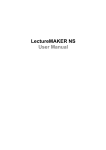
Temperature data is represented by a 9-bit, two‟s
complement word with an LSB (least significant
bit) equal to 0.5°C. For positive temperature
readings simply divide by two to convert to
centigrade. The table in Figure 14 opposite gives
some example conversions.
Figure 14: Example temperature readings and the
corresponding SENSOR.CSV values.
Temperature
Binary
Hex
+125°C
0 1111 1010
0FAh
+25°C
0 0011 0010
032h
+0.5°C
0 0000 0001
001h
0°C
0 0000 0000
000h
−0.5°C
1 1111 1111
1FFh
−25°C
1 1100 1110
1CEh
−55°C
1 1001 0010
192h
VER,2,6,6
FIL,C:\Development\SenseCam\firmware\PIC\main_v22.c,10:52:21,16-May-06
SYS,00000167,0x00,0x03,0x1f,0xff
RTC,2006,06,19,12,28,02
ACC,12,28,07,00034,00848,00036
TMP,12,28,07,00047
CLR,12,28,07,03756
PIR,12,28,07,1
BAT,12,28,07,41821
CAM,12,28,11,00000230.JPG,M
...
Figure 15: Example SENSOR.CSV file entries.
SenseCam v2.3 User Guide
Page 22 of 31
10/03/2009
Company confidential proprietary information. Do not distribute.
© 2009 Microsoft Corporation, all rights reserved.
Sensor/meaning
Interpretation
ACC
Accelerometer
Raw x, y and z acceleration values in 1/819ths of a g
with a constant 2048 offset
CLR
Colour light sensor
The sensed value for „white‟ light
PIR
Passive infrared
detector
Whether the sensor is currently triggered or not (1 =
triggered, 0 = not)
TMP
Temperature sensor
Temperature in ½ degrees Celsius (stored as two‟s
complement, see below)
BAT
Battery
Battery terminal voltage in hundreds of microvolts.
CAM Image capture
Image filename, reason (P = PIR activated, T= timer,
M = manual capture, L=light-level change)
RTC
Real-time clock
Year, month, day, hour, minute, second.
FIL
Filename
Directory path to the „main.c‟ file of the build, time
of build (hh:mm:ss) and date of build (dd-Mmm-yy).
VER
Version of
firmware
Major, middle, minor
SYS
System information
Camera serial number, brown-out count, watchdog
timeout count, config0 and config1 bits setting. The
serial number is actually recorded as hex, but our
numbering convention is to use BCD so it actually
reads out as if it were decimal.
Figure 16: Keywords used in the SENSOR.CSV file and their meanings.
5.4. BOOT.BAT system file
There is an optional file called BOOT.BAT on the SenseCam flash drive in the \SYSTEM
folder. BOOT.BAT lists a sequence of commands that will be executed every time the
SenseCam boots up, i.e. following a hard power-cycle using the hidden slide switch or
following USB disconnection (from a PC or battery charger). The commands that may be
included in BOOT.BAT are listed below. Note that the BOOT.BAT file is optional; if it is
not present or if it contains no commands, then the SenseCam will just exhibit the default
behaviours.
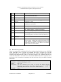
fast
Summary:
Turn fast charging on or off
Syntax:
fast „y‟|‟n‟
Description: The fast command can be used to override the default charging
behaviour (see Section 4.8). Slow charging may be needed if
connecting the SenseCam causes errors on the USB bus.
Example:
fast n
SenseCam v2.3 User Guide
Page 23 of 31
10/03/2009
Company confidential proprietary information. Do not distribute.
© 2009 Microsoft Corporation, all rights reserved.
gap
Summary:
Specify period for timer based snapshots
Syntax:
gap <time-interval>
Description: The gap command can be used to very roughly specify interval delay
between successive snapshots for timer-based image capture. <timerinterval> is the interval specified in seconds ranging from 1 second to
16000 seconds (~4½ hours). If no image has been captured for <timerinterval> seconds then an automatic snapshot will be performed.
Examples: gap 20
GAP 192
gap 2
#
Summary:
comment
Syntax:
# <comment-string>
Description: The # command can be used to insert comments into the BOOT.BAT
file without incurring syntax errors. <comment-string> is simply a line
of text which will be echoed to the debug console. The line must have
the „#‟ character as the first character on the line and is otherwise
ignored by the SenseCam command line parser.
Examples: # This is a plain old comment which will be ignored by the parser
# The next command is a comment too
# … just as the last line was a comment
trig
Summary:
Set trigger mode
Syntax:
trig <trigger-bitmask>
Description: The trig command can be used to specify the active trigger
mechanisms during SenseCam operation. This can be used to enable
or disable specific sensor input. The <trigger-bitmask> supplied must
be the inclusive OR of one or more of the following bits:
0x0002
Sensor-based (PIR, light & accelerometer) triggers
0x0100
Manual button-based trigger
0x0200
Timer-based trigger
0x0400
PIR trigger
0x0800
Light level trigger
0x1000
Accelerometer trigger
Note: if the „enable sensor based triggers‟ (0x0002) bit is not set then
the PIR, light level and accelerometer sensing trigger settings are
ignored and only the manual button and timer based trigger settings are
used.
Important: the bitmask parameter may be specified in decimal or
hexadecimal. For hexadecimal values it is important to prefix the
bitmask with the „0x‟ string.
SenseCam v2.3 User Guide
Page 24 of 31
10/03/2009
Company confidential proprietary information. Do not distribute.
© 2009 Microsoft Corporation, all rights reserved.
Examples:
trig 0x1F02
trig 0x0100
trig 0x0200
trig 0x0300
trig 0x1C02
trig 0x0402
; manual, timer-based, sense-driven camera (default)
; manual digital capture only
; timer-based capture only
; manual and timer-based capture only
; sense-driven only (no manual/timer-based photos)
; only run as stationary PIR monitoring camera
tim, dat
Summary:
Syntax:
set real-time clock time and date
tim <hours> <minutes> <seconds>
dat <day-of-month> <month-of-year> <year>
Description: Set the real-time clock to specific values. Note that the BOOT.BAT
file will need to be modified manually after the tim or dat commands
have been used to prevent the real-time clock from being set to the
same values every time the SenseCam executes the BOOT.BAT file.
Manual time setting is best achieved by using the TIME.CSV file (see
Section 5.5 below).
eewrite
Summary:
Specify non-volatile configuration settings
Syntax:
eewrite <config-byte> <new-value>
Description: Several non-volatile configuration bytes which control various aspects
of SenseCam operation are stored in the on-chip microcontroller
EEPROM. These may be overwritten using the eewrite command by
specifying the <config-byte> number and the <new-value> to store at
that location. Since this configuration information is stored in nonvolatile memory, having set the desired values, the eewrite commands
in the BOOT.BAT file may be deleted.
Most of the configuration bytes should not be altered by the end user.
Altering their contents may cause problems operating the SenseCam
and in the worst case will render it inoperable. Do not use this
command unless you are confident that you understand what effect it
will have! See 5.7 below for more detail on useful settings.
Examples: eewrite 8
;
eewrite 9 0x02 ; no power saving
Figure 17: BOOT.BAT commands.
5.5. TIME.CSV system file
The TIME.CSV file in the \SYSTEM directory is used to update the real-time clock on the
SenseCam. On boot up (following a USB disconnect and a power-on) the SenseCam will
use the information in the TIME.CSV file to set the real-time clock, and will then delete the
TIME.CSV file. See Section 3.5 for more details on this process.
SenseCam v2.3 User Guide
Page 25 of 31
10/03/2009
Company confidential proprietary information. Do not distribute.
© 2009 Microsoft Corporation, all rights reserved.
The TIME.CSV file can contain up to two lines, one for setting the time of day and the other
for setting the date. The format for these two lines is the same as the tim and dat
BOOT.BAT commands (either spaces or commas can be used as parameter delimiters).
5.6. SenseCam action on connection to and disconnection from USB
When the SenseCam detects a USB connection, it stores the current real-time clock value in
its internal non-volatile memory. It then shuts down the file system and peripherals, makes
the SD card available to the USB device controller, and enters its low-power sleep mode.
On disconnection from USB, SenseCam looks for the file TIME.CSV in the \SYSTEM
directory. If it exists, the time difference between the time stored in TIME.CSV and the time
stored internally is calculated and then added to the (continually advancing) SenseCam realtime clock. This mechanism ensures that SenseCam time is set to the time of the PC, no
matter how long the camera was docked for. After setting the real-time clock in this way,
the SenseCam then deletes TIME.CSV.
Having altered the real-time clock if appropriate, the SenseCam will continue to boot up.
During this process it will retrieve the configuration settings from non-volatile memory, and
finally it will read and act on the BOOT.BAT file in the \SYSTEM directory (see below for
details). It is possible that BOOT.BAT file commands will override defaults set in the nonvolatile memory.
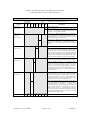
5.7. Non-volatile configuration options
There are two configuration bytes in the non-volatile memory of the SenseCam that may be
changed by means of the eewrite command in the BOOT.BAT file. The current values of
these configuration bytes are recorded in the SYS entry in the SENSOR.CSV file.
Modifying factory-shipped configuration options is not recommended since it may
adversely affect the operation of the SenseCam, and if the commands are entered in error
it may render the SenseCam inoperable.
If the config0 and config1 bit settings described in the tables below are to be modified
after the camera has been shipped, it is recommended that all bit settings in positions
which are not explicitly described below should be preserved from the values in the
default original SENSOR.CSV records. This will avoid inadvertently changing other
internal (potentially critical) functionality.
The address and bit meanings of these two configuration bytes are as follows:
SenseCam v2.3 User Guide
Page 26 of 31
10/03/2009
Company confidential proprietary information. Do not distribute.
© 2009 Microsoft Corporation, all rights reserved.
config0 byte [eewrite address 8]
Control
0
0
0
1
1
1
1
1
b7
b6
b5
b4
b3
b2
b1
b0
default factory-programmed value: 0x1F
Description
Fast charge
0
Turn off fast charging.
bitmask 0x01
1
Turn on fast charging. See Section 4.8 for more details
on this. Use the fast command in BOOT.BAT in
preference. This is the default setting.
Push-button
mapping
0
Button map A. Manual snapshot button is mapped to the
top of the SenseCam. Power/standby mapped to top side
button of SenseCam. Use this if you are keen to have the
shutter button on the top of the camera.
1
Button map B. Manual snapshot is mapped to the bottom
side button of SenseCam. Power/standby button is
mapped to the top of SenseCam. This is the default
setting.
bitmask 0x04
Image inversion
0
Turn off image inversion correction.
bitmask 0x08
1
Turn on image inversion correction. This is the default
setting. Natively the images produced by the SenseCam
are up-side down. More recent builds of the SenseCam
firmware can correct for this by commanding the built-in
camera module to produce images right-side-up. If this
option is not selected, images will appear up-side down
until imported by the MSRC SenseCam Image Importer.
Double snap
0
Turn off double-snap option.
Captures images
marginally faster but with less accurate exposure setting.
1
Turn on double-snap option.
This default setting
captures two images back-to-back – the first image will
be used by the built-in camera module to set up the
exposure for the following image. Saving an image to
flash memory takes much more time than capturing it, so
this double-snapping doesn‟t have much adverse effect
on performance.
bitmask 0x10
Auto battery save
0
Turn on automatic battery save feature. The SenseCam
will automatically go into low power standby mode if the
battery voltage is below a critical threshold. This has the
effect of preserving the time and date settings of the
SenseCam until such a time as it is fully recharged and
ready to use again. This is the default setting.
1
Turn off the automatic battery save feature. If this option
is used the SenseCam will attempt to continue running
until the battery is exhausted – potentially with
unpredictable results (various peripherals and storage of
data in the SenseCam may stop operating correctly at
different points in time). In particular, the real-time
clock is likely to lose the time and date settings and some
image degradation/file corruption is likely to be seen
towards the end of logged data.
bitmask 0x20
b7
b6
b5
b4
b3
b2
b1
b0
Figure 18: SenseCam config0 byte (address 8) bit fields and their meanings.
SenseCam v2.3 User Guide
Page 27 of 31
10/03/2009
Company confidential proprietary information. Do not distribute.
© 2009 Microsoft Corporation, all rights reserved.
Config1 byte [eewrite address 9]
Control
1
1
1
1
1
1
1
1
b7
b6
b5
b4
b3
b2
b1
b0
Description
0
Turn off camera power saving. The internal camera
sensor is not turned off after each image capture. This
may be marginally faster.
1
Turn on camera power saving. The internal camera
sensor is turned off after each image capture to conserve
battery power. This is the default setting.
Camera power
saving
bitmask 0x01
default factory-programmed value: 0xFF
Camera
reinitialisation
0
Turn off camera re-initialisation.
Prevents reinitialisation of the internal camera sensor prior to each
and every image capture. This may be marginally faster.
bitmask 0x02
1
Turn on camera re-initialisation. The internal camera
sensor is re-initialised prior to each and every image
capture. This is particularly required if the sensor has
been powered down due to camera saving (see above).
This is the default setting.
b7
b6
b5
b4
b3
b2
b1
b0
Figure 19: SenseCam config1 byte (address 9) bit fields and their meanings.
SenseCam v2.3 User Guide
Page 28 of 31
10/03/2009
Company confidential proprietary information. Do not distribute.
© 2009 Microsoft Corporation, all rights reserved.
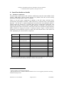
6. SenseCam hardware details
6.1. Hardware components
The SenseCam is built around a PIC 18F8722 6 MIPS microcontroller with 128KB of flash
memory, 4KB RAM, copious general purpose I/O (GPIO) lines and several on-chip
peripherals including PWM, UART, I2C and SPI.
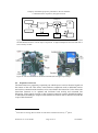
Figure 20 lists the major components in addition to the PIC along with their basic
specifications and method of interface. USB connectivity is achieved using a non-standard
approach – the SD card is actually multiplexed between the PIC microcontroller (which is
selected when the SenseCam is recording data) and an off-the-shelf USB-to-SD card
interface chip (which is selected when a USB connection is detected). This allows us to
support high speed USB 2.0 operation, which allows data to be transferred at approximately
4MB/s (around 175 images per second, or 10,000 per minute). Figure 21 shows the basic
architecture of the SenseCam. Figure 22 depicts the front and the back of the SenseCam
PCB, highlighting the main hardware components.
Component
Part number
Specification
Interface
Flash memory
Standard SD card
To 2GB (1GB standard)
SPI
Camera module
CoMedia C328-7640
VGA (onboard JPEG compression)
UART
Camera lens
Marshall Electronics V4301.9-2.0FT-IRC
119º (diag) wide-angle lens w/ IR filter
n/a
Accelerometer
Kionix KXP84
Tri-axis
I2C
Temperature
Nat Semi LM75
Range -55 to +125ºC, ±2ºC
I2C
Real-time clock
Maxim/Dallas DS1340
Light level
TAOS TCS230
RGB intensity
PWM
Passive IR (PIR)
Seiko SKP-MS401
Miniature form factor
GPIO
Push buttons
Omron B3F-3150
GPIO
Murata PKLCS1212
PWM
Sounder
4
I2C
Audio recording
Oki MS87V1021
2Mb DRAM for 60s audio at 8ksps
SPI
GPS5
n/a
External GPS unit
BT
Figure 20: The main peripherals (including all sensors) in the v2.3 SenseCam, with a summary of
their specification and the method of interface to the PIC microcontroller.
4
Audio recording is still under development.
GPS information from a standalone Bluetooth GPS receiver can be logged by the SenseCam using
the Bluetooth plug-in unit.
5
SenseCam v2.3 User Guide
Page 29 of 31
10/03/2009
Company confidential proprietary information. Do not distribute.
© 2009 Microsoft Corporation, all rights reserved.
multiplexer
SD
card
PIC µC
sensors, I/O
expansion
USB
Power
Figure 21: The basic architecture of the SenseCam. A PIC microcontroller (6 MIPS, 128kB flash
and 4kB RAM) interfaces with the major components. A digital multliplexer allows the SD card to
be accessed by the PIC.
Figure 22: The front and back of the SenseCam PCB (left and right respectively).
6.2. Expansion connector
The SenseCam has a proprietary expansion port which exposes various electrical signals on
the bottom of the unit. This allows extra hardware components such as additional sensors
and wireless communications interfaces to be retro-fitted to the SenseCam. It also allows the
SenseCam firmware to be updated and facilitates both on-chip and command line
debugging. Using signals exposed via the expansion connector requires detailed knowledge
of the SenseCam hardware coupled with customised firmware and is therefore beyond the
scope of this document.6
6
At the time of writing, Microsoft has not shared this information with any 3 rd parties.
SenseCam v2.3 User Guide
Page 30 of 31
10/03/2009
Company confidential proprietary information. Do not distribute.
© 2009 Microsoft Corporation, all rights reserved.
6.3. More information
More information about the design rationales behind the SenseCam is given in “SenseCam:
A Retrospective Memory Aid”, Steve Hodges, Lyndsay Williams, Emma Berry, Shahram
Izadi, James Srinivasan, Alex Butler, Gavin Smyth, Narinder Kapur and Ken Wood, in P.
Dourish and A. Friday (Eds.): UbiComp 2006, LNCS 4206, pp. 177 – 193, 2006. ©
Springer-Verlag Berlin Heidelberg 2006. A copy of this paper is available on request.
SenseCam v2.3 User Guide
Page 31 of 31
10/03/2009