1
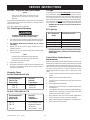
SPECIFICATIONS
Refer to Outfit Parts Manual for the specifications of your air
compressor. Use only a fuse or circuit breaker that is the same
rating as the branch circuit the air air compressor is operated on.
If the air compressor is connected to a circuit protected by fuses,
use dual element time delay fuses, as noted in that Service
Manual. Some air compressors require a magnetic starter.
Check Outfit Parts Manual for magnetic starter requirements.
Improper electrical installation of this product may void its warranty and your fire insurance.
Have circuit wiring performed by qualified personnel such as a licensed electrician who is
familiar with the current national electric code and any prevailing local electrical codes.
GLOSSARY
CFM: Cubic feet per minute.
Cut-In Pressure: While the motor is off, air tank pressure drops
as you continue to use your accessory. When the air tank
pressure drops to a certain low level the motor will restart
automatically. The low pressure at which the motor automatically
re-starts is called “cut-in pressure.”
Cut-Out Pressure: When you turn on your air compressor and
it begins to run, air pressure in the air tank begins to build. It
builds to a certain high pressure before the motor automatically
shuts off - protecting your air tank from pressure higher than
its capacity. The high pressure at which the motor shuts off is
called "cut-out pressure."
SCFM: Standard cubic feet per minute; a unit of measure of air
delivery.
PSIG: Pounds per square inch gauge; a unit of measure of
pressure.
ASME: American Society of Mechanical Engineers; made,
tested, inspected and registered to meet the standards of the
ASME.
California Code: Unit may comply with California Code 462
(l) (2)/(M) (2). Specification/Model Label is on the side of the air
tank on units that comply with California Code.
To Lock Out Power: Place a lock on the line power switch so
no one else can turn on the power.
DUTY CYCLE
All DeVilbiss Air Power manufactured air compressors should
be operated on not more than a 50% duty cycle. This means
an air compressor that pumps more than 50% of one hour, is
considered misuse, because the air compressor is undersized
for the required air demand. Maximum air compressor pumping
time per hour is 30 minutes.
INSTALLATION
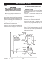
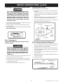
Location of the Air Compressor
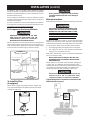
The flywheel side of the outfit should be placed toward the wall
and protected with a totally enclosed belt guard. In no case
should the flywheel be closer than 12 to 18 inches from the wall
or other obstruction that will interfere with the flow of air
through the fan bladed flywheel. The area should allow space
on all sides for air circulation and for ease of normal maintenance. Keep the outfit away from areas which have dirt, vapor
and volatile fumes in the atmosphere which may clog and gum
up the intake filter and valves, causing inefficient operation.
Where this is not practical a remote air intake is recommended.
THE MANIFOLD ASSEMBLY DOES NOT PROVIDE ADEQUATE STABILITY OR SUPPORT FOR
LIFTING THE UNIT. IF THE OUTFIT MUST BE
MOVED, USE THE AIR TANK FOR LIFTING.
This air compressor should be permanently mounted in a place
on a level floor. Operate the air compressor in a clean, dry and
well ventilated area. The air intake filter must be kept clear of
obstructions which could reduce air delivery of the air compressor.
Note
Where a remote air intake is used, enlarge the size
of the air intake piping by one pipe size for each 10
feet of length.
The air compressor should be located at least 12 inches away
from walls or other obstructions that could interfere with the
flow of air through the fan bladed flywheel. The air compressor
crankcase and head are designed with fins to provide proper
cooling.
7
MG6-OLVERT-3B
Rev. 2 6/27/00