1
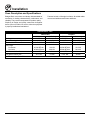
1060
GAS DECK OVEN
INSTALLATION - OPERATION - MAINTENANCE
BLODGETT OVEN COMPANY
www.blodgett.com
44 Lakeside Avenue, Burlington, Vermont 05401 USA Telephone: (802) 658-6600 Fax: (802)864-0183
PN 17969 Rev M (2/15)
© 2015 - G.S. Blodgett Corporation
Your Service Agency’s Address:
Model
Serial number
Oven installed by
Installation checked by
TABLE OF CONTENTS
IMPORTANT
WARNING: Improper installation, adjustment, alternation,
service or maintenance can
cause property damage, injury or death. Read the instllation, operation and maintenance instructions thoroughly
before installing or servicing
this equipment.
INSTRUCTIONS TO BE FOLLOWED IN THE EVENT THE
USER SMELLS GAS MUST BE
POSTED IN A PROMINENT LOCATION. This information may
be obtained by contacting your
local gas supplier.
INSTALLATION
Oven Description and Specifications. . . . . . . . . . . . . . . . . . . . . . . . . . . . . . . . . . . . . . . . 2
Delivery and Location. . . . . . . . . . . . . . . . . . . . . . . . . . . . . . . . . . . . . . . . . . . . . . . . . . . . . 3
Oven Assembly. . . . . . . . . . . . . . . . . . . . . . . . . . . . . . . . . . . . . . . . . . . . . . . . . . . . . . . . . . . 4
Packaging. . . . . . . . . . . . . . . . . . . . . . . . . . . . . . . . . . . . . . . . . . . . . . . . . . . . . . . . . . . . 4
Leg Attachment. . . . . . . . . . . . . . . . . . . . . . . . . . . . . . . . . . . . . . . . . . . . . . . . . . . . . . . 4
caster attachment. . . . . . . . . . . . . . . . . . . . . . . . . . . . . . . . . . . . . . . . . . . . . . . . . . . . . 4
Double Section Assembly. . . . . . . . . . . . . . . . . . . . . . . . . . . . . . . . . . . . . . . . . . . . . . 5
3 Piece Deflector Assembly. . . . . . . . . . . . . . . . . . . . . . . . . . . . . . . . . . . . . . . . . . . . 5
Ultra Rokite Shelves. . . . . . . . . . . . . . . . . . . . . . . . . . . . . . . . . . . . . . . . . . . . . . . . . . . 5
Deck Seal. . . . . . . . . . . . . . . . . . . . . . . . . . . . . . . . . . . . . . . . . . . . . . . . . . . . . . . . . . . . 6
Flue Plates. . . . . . . . . . . . . . . . . . . . . . . . . . . . . . . . . . . . . . . . . . . . . . . . . . . . . . . . . . . 6
Leveling the Oven. . . . . . . . . . . . . . . . . . . . . . . . . . . . . . . . . . . . . . . . . . . . . . . . . . . . . 6
Adjustments Associated with Initial Installation. . . . . . . . . . . . . . . . . . . . . . . . . . . 6
FOR YOUR SAFETY
Ventilation. . . . . . . . . . . . . . . . . . . . . . . . . . . . . . . . . . . . . . . . . . . . . . . . . . . . . . . . . . . . . . . . 7
Do not store or use gasoline or
other flammable vapors or liquids in the vicinity of this or any
other appliance.
Gas Connection. . . . . . . . . . . . . . . . . . . . . . . . . . . . . . . . . . . . . . . . . . . . . . . . . . . . . . . . . 10
The information contained in this
manual is important for the proper installation, use, and maintenance of this oven. Adherence
to these procedures and instructions will result in satisfactory
baking results and long, trouble free service. Please read
this manual carefully and retain
it for future reference.
Initial Startup. . . . . . . . . . . . . . . . . . . . . . . . . . . . . . . . . . . . . . . . . . . . . . . . . . . . . . . . . . . . 13
Utility Connections - Standards and Codes. . . . . . . . . . . . . . . . . . . . . . . . . . . . . . . . . . 9
Gas Piping. . . . . . . . . . . . . . . . . . . . . . . . . . . . . . . . . . . . . . . . . . . . . . . . . . . . . . . . . . 10
Pressure Regulation and Testing.. . . . . . . . . . . . . . . . . . . . . . . . . . . . . . . . . . . . . . 11
Gas Hose Restraint. . . . . . . . . . . . . . . . . . . . . . . . . . . . . . . . . . . . . . . . . . . . . . . . . . 12
OPERATION
Safety Information.. . . . . . . . . . . . . . . . . . . . . . . . . . . . . . . . . . . . . . . . . . . . . . . . . . . . . . . 14
Oven Control. . . . . . . . . . . . . . . . . . . . . . . . . . . . . . . . . . . . . . . . . . . . . . . . . . . . . . . . . . . . 15
General Guidelines for Operating Personnel. . . . . . . . . . . . . . . . . . . . . . . . . . . . . . . . 16
MAINTENANCE
Cleaning and Preventative Maintenance. . . . . . . . . . . . . . . . . . . . . . . . . . . . . . . . . . . 17
Troubleshooting Guide. . . . . . . . . . . . . . . . . . . . . . . . . . . . . . . . . . . . . . . . . . . . . . . . . . . 18
ERRORS: Descriptive, typographic or pictorial errors are
subject to correction. Specifications are subject to change
without notice.
Installation
Oven Description and Specifications
Blodgett Deck ovens have set industry wide standards of
excellence for baking characteristics, performance and
reliability. They remain unsurpassed for product quality.
Features include a full angle iron frame, all welded radius
corners and stainless steel fronts and doors.
Simplicity of design and quality construction throughout
assure years of trouble free service when the equipment
is properly installed and maintained.
Heating Value
Specific Gravity (air=1.0)
Gas Manifold Pressure
Oven Input
Per Burner
Per Oven
Main Burner Orifice Size
Pilot Burner Orifice Size
NOTE: * - Multiple Twist Drill
gas ratings - 1060
Natural Gas
US Units
SI Units
1000 BTU/hr
37.3 MJ/m3
0.63
0.63
3.5” W.C.
0.87 kPa
Propane
US Units
2550 BTU/hr
1.53
10” W.C.
SI Units
95.0 MJ/m3
1.53
2.49 kPa
42,500 BTU/hr
12.4 kW
42,500 BTU/Hr
12.4 kW
85,000 BTU/Hr
30 MTD*
.021” Dia.
24.9 kW
3.3 mm
.53 mm
85,000 BTU/Hr
48 MTD*
.0115” Dia.
24.9 kW
1.93 mm
.29 mm
2
Installation
Delivery and Location
Delivery and inspection
It is essential that an adequate air supply to the oven be
maintained to provide a sufficient flow of combustion and
ventilation air.
All Blodgett ovens are shipped in containers to prevent
damage. Upon delivery of your new oven:
•
•
Inspect the shipping container for external damage.
Any evidence of damage should be noted on the
delivery receipt which must be signed by the driver.
Uncrate the oven and check for internal damage.
Carriers will accept claims for concealed damage if
notified within fifteen days of delivery and the shipping container is retained for inspection.
The Blodgett Oven Company cannot assume responsibility for loss or damage suffered in transit. The carrier assumed full responsibility for delivery in good order when
the shipment was accepted. We are, however, prepared
to assist you if filing a claim is necessary.
The well planned and proper placement of your oven will
result in long term operator convenience and satisfactory
performance.
•
Oven body left side - 6” (15 cm)
•
Oven body back - 6” (15 cm)
•
Oven body bottom - 6” (15 cm)
The following clearance must be available for servicing.
•
•
Keep the oven area free and clear of all combustibles such as paper, cardboard, and flammable
liquids and solvents.
•
Do not place the oven on a curb base or seal to
a wall. This will restrict the flow of air and prevent
proper ventilation. Pilot outages or yellow, floating
flames on the main burners are indicative of a lack of
secondary air.
•
The oven must be installed with the legs supplied by
the manufacturer.
1. Pull out control panel. The rating plate is attached to
the inside of the control compartment.
The following clearances must be maintained between
the oven and any combustible or non-combustible construction.
Oven body right side - 6” (15 cm)
Place the oven in an area that is free of drafts.
Before making any utility connections to this oven, check
the rating plate to be sure the oven specifications are
compatible with the gas and electrical services supplied
for the oven.
oven location
•
•
Oven body left side - 12” (30.5 cm)
NOTE: On gas models, routine servicing can usually be
accomplished within the limited movement provided by the gas hose restraint. If the oven needs
to be moved further from the wall, the gas must
first be turned off and disconnected from the oven
before removing the restraint. Reconnect the restraint after the oven has been returned to its normal position.
3
Installation
Oven Assembly
Packaging
Leg Attachment
Before beginning assembly and installation of the oven,
check that all necessary components have been received.
In addition to the oven itself, legs, the proper vent, and/or
other accessories may be required.
1. Put the oven onto a genie lift with the bottom of the
oven down. Be careful not to damage the louvered
panel under the oven.
2. Each leg is attached by three bolts to the underside of
the oven base frame.
Single Sections
1060 with Steel Deck
•
•
caster attachment
Legs, regulator, set of flue plates, draft diverter and
steel deck are shipped in the oven.
1. Bolt supports to oven with 1/2-13 hex head bolts
(casters with brakes should be facing front of oven.)
Drafthood (when supplied) is packed separately.
2. Carefully place oven onto the casters. (It will be necessary to have several persons lift oven off the pallet
and set it onto the casters). Engage brakes on front
casters.
1060 with Ultra Rokite Decks
•
Legs, regulator, set of flue plates and draft diverter
are shipped in oven.
•
Ultra Rokite decks are packed in a separate carton.
•
Drafthood (when supplied) is packed separately.
NOTE: A fixed restraint must be provided if casters are
used in conjunction with a flexible connector for
movable appliances. This restraint must secure
the oven to a non-movable surface to eliminate
stress on the connector. If the oven is moved, the
restraint must be reconnected after the oven is
returned to it’s normal position.
Double Sections
1060 with Steel Deck
•
Legs and bolts, regulator, set of flue plates and steel
deck are packed in the lower section.
•
Regulator, set of flue plates, draft diverter and steel
deck are packed in the upper section.
•
Crown angle leg frame is packed in a separate
carton.
•
Drafthood (when supplied) is packed in a separate
carton.
1060 with Ultra Rokite Decks
•
Legs and bolts, regulator, set of flue plates are
packed in the lower section.
•
Regulator, draft diverter and a set of flue plates are
packed in the upper section.
•
Ultra Rokite decks are packed in two separate cartons.
•
Crown angle leg frame is packed in a separate
carton.
•
Drafthood (when supplied) is packed in a separate
carton.
4
Installation
Oven Assembly
Double Section Assembly
3 Piece Deflector Assembly
1. Fasten 12” (305 mm) legs to lower section.
1. Deflectors are shipped in place in the oven. No assembly is required.
2. Remove the sheet metal flue cover on bottom of UPPER SECTION FLUE ONLY and save the two screws.
2. Remove the shipping clip located in the back center
of each deflector before inserting two-piece shelf assembly.
3. Fasten crown angle leg frame to upper sections.
4. Insert double oven flue connector into upper oven
section flue until it is flush with the base angle. Temporarily hold in place with tape.
Ultra Rokite Shelves
1. Slide the 12” wide Ultra Rokite shelf through the door
opening to the rear of the oven until it drops into the
shelf support.
5. Install upper section on bottom section.
6. Remove tape and slide flue connector into position
over the collar of the bottom section.
2. Slide one of the two 24” wide shelves through the
door opening to the rear on the center shelf until it is
within the shelf support. Slide all the way to the left
until it drops down in place.
7. Fasten flue connector to bottom section with screws
from the flue cover.
8. Install drafthood or draft diverter with screws provided.
3. Slide the other 24” wide shelf through the door opening to the rear on the center shelf until it is within the
shelf support. Slide all the way to the right until it
drops down in place.
4. Pry the three sections inward so the joints close.
5. Install the deck seal between the door and the frame.
NOTE: Due to the weight of the Ultra Rokite shelves,
take care to avoid injury to yourself or damage to the shelves when sliding sections into
the oven.
Figure 1
Figure 2
5
Installation
Oven Assembly
Deck Seal
Leveling the Oven
1. Place the long lip of the deck seal in front of the shelf
support angle. Place the shorter lip with the notches
between the shelf support angle and the shelf.
Ovens are equipped with NSF listed adjustable sanitary
legs.
1. Level ovens side to side and front to back by placing
spirit level on base frame of lower section.
2. Push seal down into place.
2. Adjust leg feet in or out as appropriate.
Adjustments Associated with Initial
Installation
Each oven, and its component parts, have been thoroughly tested and inspected prior to shipment. However, it is
often necessary to further test or adjust the oven as part
of a normal and proper installation. These adjustments
are the responsibility of the installer, or dealer. Since
these adjustments are not considered defects in material or workmanship, they are not covered by the Original
Equipment Warranty. They include, but are not limited to:
•
calibration of the thermostat
•
adjustment of the doors
•
burner adjustments
Flue Plates
•
leveling
1. Insert the back end of the flue plate in the vertical
channel in the rear of the oven compartment.
•
testing of gas pressure
•
tightening of fasteners
Figure 3
2. Swing the flue plate outward toward the oven side
wall.
No installation should be considered complete without
proper inspection, and if necessary, adjustment by qualified installation or service personnel.
3. Raise the front end of the flue plate about 1/2”. slip
the two tabs on the flue plate in the matched angle on
the front wall.
4. Drop the flue plate down into place.
Figure 4
6
Installation
Ventilation
Canopy Type Exhaust Hood
Blodgett gas deck ovens are direct fired. Heat and flue
products from the burners are introduced directly into the
baking compartment. As a result, improper venting can
have a detrimental effect on the baking characteristics
of the oven. A properly designed ventilation system will
allow the oven to function properly, while removing unwanted vapors and products of combustion from the operating area.
A mechanically driven, canopy type exhaust hood is the
preferred method of ventilation.
The hood should be sized to completely cover the equipment plus an overhang of at least 6” (15 cm) on all sides
not adjacent to a wall. The distance from the floor to the
lower edge of the hood should not exceed 7’ (2.1m).
The capacity of the hood should be sized appropriately
with provisions for an adequate supply of make up air.
Capacity is generally expressed in ft3/min (CFM). 1 CFM
of natural gas burned with just enough air for complete
combustion produces 11 CFM of combustion products.
In virtually all appliances some excess air is used. This
volume of excess air is added to the flue products flowing from the appliance.
This oven may be vented using either:
•
A mechanically driven, canopy type, exhaust hood,
or
•
A direct flue arrangement.
U.S. and Canadian installations
Refer to your local ventilation codes. In the absence of
local codes, refer to the National ventilation code titled,
“Standard for the Installation of Equipment for the Removal of Smoke and Grease Laden Vapors from Commercial Cooking Equipment”, NFPA-96-Latest Edition.
NOTE: Consult your local exhaust hood contractor for
your specific installation.
Installing the canopy hood draft diverter
Ovens ordered for hood venting are supplied with a draft
diverter. Install the draft diverter as follows:
General export installations
Installation must conform with Local and National installation standards. Local installation codes and/or requirements may vary. If you have any questions regarding the
proper installation and/or operation of your Blodgett oven,
please contact your local distributor. If you do not have a
local distributor, please call the Blodgett Oven Company
at 0011-802-658-6600.
1. Place the diverter over the flue connector with the
open area facing the front of the oven.
2. Secure both ends with the sheet metal screws provided.
Draft Diverter
The Blodgett Oven Company cannot assume responsibility for loss or damage suffered as a result of improper
installation.
WARNING:
Failure to properly vent the oven can be hazardous to the health of the operator and may
result in operational problems, unsatisfactory
baking and possible damage to the equipment.
Front of Oven
Damage sustained as a direct result of improper ventilation will not be covered by the Manufacturer’s warranty.
Figure 5
7
Installation
Ventilation
Direct Flue Arrangement
Venting Problems
When the installation of a mechanically driven exhaust
hood is impractical the oven may be vented by a direct
flue arrangement.
Blodgett gas deck ovens use the natural principal of heat
rising as the basic method of ventilation. If the venting of
any deck oven is either restricted or forced in any way
the baking characteristics of the oven will be adversely
affected.
WARNING!!
It is essential that the direct flue be installed
as follows. Incorrect installation will result in
unsatisfactory baking and oven damage.
Examples of forced venting include:
The flue must be class B or better with a diameter of 10”
(25.4 cm). The height of the flue should rise 6-8 ft (2-2.5
m) above the roof of the building or any proximate structure. Never direct vent the oven into a hood. The flue
should be capped with a UL Listed type vent cap to isolate
the unit from external environmental conditions.
•
installation of a fan in a direct vent pipe
•
use of a canopy type hood without the draft diverter
Examples of restricted venting include:
•
use of tees and elbows
•
long horizontal runs
Insufficient make-up air can cause heated air and combustibles to remain in the oven shortening the life of the
components.
The direct vent cannot replace air consumed and vented
by the oven. Provisions must be made to supply the room
with sufficient make-up air. Total make-up air requirements for each oven section should be approximately 30
CFM per section. To increase the supply air entering the
room, a ventilation expert should be consulted.
Installing the draft hood
Ovens ordered for direct venting are supplied with a draft
hood. Install the draft hood as follows:
1. Place the draft hood over the flue connector.
2. Secure both ends with the sheet metal screws provided.
Flue
Draft Hood
Front of Oven
Figure 6
8
Installation
Utility Connections - Standards and Codes
THE INSTALLATION INSTRUCTIONS CONTAINED
HEREIN ARE FOR THE USE OF QUALIFIED INSTALLATION AND SERVICE PERSONNEL ONLY. INSTALLATION OR SERVICE BY OTHER THAN QUALIFIED
PERSONNEL MAY RESULT IN DAMAGE TO THE OVEN
AND/OR INJURY TO THE OPERATOR.
U.S. and Canadian installations
Qualified installation personnel are individuals, a firm,
a corporation, or a company which either in person or
through a representative are engaged in, and responsible
for:
General export installations
•
Installation must conform with local codes, or in the absence of local codes, with the National Fuel Gas Code,
NFPA54/ANSI Z223.1-Latest Edition, the Natural Gas Installation Code CAN/CGA-B149.1 or the Propane Installation Code, CAN/CGA-B149.2 as applicable.
Installation must conform with Local and National installation standards. Local installation codes and/or requirements may vary. If you have any questions regarding the
proper installation and/or operation of your Blodgett oven,
please contact your local distributor. If you do not have a
local distributor, please call the Blodgett Oven Company
at 0011-802-658-6600.
the installation or replacement of gas piping and the
connection, installation, repair or servicing of equipment.
Qualified installation personnel must be experienced in
such work, familiar with all precautions required, and have
complied with all requirements of state or local authorities
having jurisdiction.
9
Installation
Gas Connection
Gas Piping
Maximum Capacity of Iron Pipe in Cubic Feet of
Natural Gas Per Hour
A properly sized gas supply system is essential for maximum oven performance. Piping should be sized to provide a supply of gas sufficient to meet the maximum demand of all appliances on the line without loss of pressure
at the equipment.
(Pressure drop of 0.5 Inch W.C.)
Nominal Size, Inches
3/4”
1”
1-1/4” 1-1/2”
2”
10
360
680
1400 2100 3950
20
250
465
950
1460 2750
30
200
375
770
1180 2200
40
170
320
660
990
1900
50
151
285
580
900
1680
60
138
260
530
810
1520
70
125
240
490
750
1400
80
118
220
460
690
1300
90
110
205
430
650
1220
100
103
195
400
620
1150
From the National Fuel Gas Code Part 10 Table 10-2
Pipe
Length (ft)
Example:
NOTE: BTU values in the following example are for natural gas.
You purchase a 1060-B deck oven to add to your existing
cook line.
1. Add the BTU rating of your current appliances.
Pitco Fryer
120,000 BTU
6 Burner Range
60,000 BTU
Deck Oven
50,000 BTU
Total
230,000 BTU
2. Add the BTU rating of the new oven to the total.
Previous Total
230,000 BTU
1060-B
85,000 BTU
New Total
315,000 BTU
Maximum Capacity of Pipe in Thousands of
BTU/hr of Undiluted L.P. Gas at 11” W.C.
(Pressure drop of 0.5 Inch W.C.)
3. Measure the distance from the gas meter to the cook
line. This is the pipe length. Let’s say the pipe length
is 40’ (12.2 m) and the pipe size is 1” (2.54 cm).
Outside Diameter, Inches
3/4”
1”
1-1/2”
10
608
1146
3525
20
418
788
2423
30
336
632
1946
40
287
541
1665
50
255
480
1476
60
231
435
1337
70
215
404
1241
80
198
372
1144
90
187
351
1079
100
175
330
1014
From the National Fuel Gas Code Part 10 Table 10-15
Pipe
Length (ft)
4. Use the appropriate table to determine the total capacity of your current gas piping.
The total capacity for this example is 320,000 BTU. Since
the total required gas pressure, 315,000 BTU is less than
320,000 BTU, the current gas piping will not have to be
increased.
NOTE: The BTU capacities given in the tables are for
straight pipe lengths only. Any elbows or other fittings will decrease pipe capacities. Contact your
local gas supplier if you have any questions.
10
Installation
Gas Connection
Pressure Regulation and Testing
Each oven is supplied with a regulator to maintain the
proper gas pressure. The regulator is essential to the
proper operation of the oven and must be installed.
It is preset to provide the oven with 3.5” W.C. (0.87 kPa)
for natural gas and 10.5” W.C. (2.50 kPa) for Propane at
the manifold.
Each section of the 1060-B series oven is rated at 85,000
BTU per hour (24.9 kW). At full demand, each section
1060-BL oven requires 85 cubic feet per hour (2.4 m3)
Natural gas or 33 cubic feet per hour (0.9 m3) Propane
gas. Each oven has been adjusted at the factory to operate with the type of gas specified on the rating plate.
W.C.
kPa
W.C.
kPa
DO NOT INSTALL AN ADDITIONAL REGULATOR
WHERE THE OVEN CONNECTS TO THE GAS SUPPLY UNLESS THE SUPPLY EXCEEDS THE MAXIMUM
PRESSURE.
Inlet Pressure
Natural
Propane
Min
Max
Min
Max
7.0
10.5
11.0
13.0
1.43
2.61
2.74
3.23
Manifold Pressure
Natural
Propane
3.5
10.0
.87
2.49
•
Inlet Pressure - the pressure of the gas before it
reaches the oven.
•
Manifold Pressure - the pressure of the gas as it
enters the main burner(s).
•
Min - the minimum pressure recommended to operate the oven.
•
Max - the maximum pressure at which the manufacturer warrants the oven’s operation.
Due to the decrease in oxygen at higher elevations,
above 2000’, the unit may need to be rerated. (The orifice
size may need to be adjusted to accomodate different air
pressures at higher elevations.) If not rerated, incomplete
combustion may occur releasing Aldehydes and CO or
Carbon Monoxide. Any of these are unacceptable and
may be hazardous to the health of the operator.
Prior to connecting the oven, gas lines should be thoroughly purged of all metal filings, shavings, pipe dope,
and other debris. After connection, the oven should be
checked for correct gas pressure.
Installation must conform with local codes, or in the absence of local codes, with the National Fuel Gas Code,
NFPA54/ANSI Z223.1-Latest Edition, the Natural Gas Installation Code CAN/CGA-B149.1 or the Propane Installation Code, CAN/CGA-B149.2 as applicable.
The oven and its individual shutoff valve must be disconnected from the gas supply piping system during any
pressure testing of that system at test pressures in excess of 1/2 psig (3.45kPa).
The oven must be isolated from the gas supply piping
system by closing its individual manual shutoff valve during any pressure testing of the gas piping system at test
pressures equal or less than 1/2 psig (3.45kPa).
11
Installation
Gas Connection
Gas Hose Restraint
WARNING!!
If the oven is mounted on casters, a commercial flexible
connector with a minimum of 3/4” (1.9 cm) inside diameter must be used along with a quick connect device.
If the restraint is disconnected for any reason
it must be reconnected when the oven is returned to its original position.
The restraint, supplied with the oven, must be used to limit
the movement of the unit so that no strain is placed upon
the flexible connector. With the restraint fully stretched the
connector should be easy to install and quick connect.
U.S. and Canadian installations
The connector must comply with the Standard for Connectors for Movable Gas Appliances, ANSI Z21.69 or
Connectors For Moveable Gas Appliances CAN/CGA6.16 and a quick disconnect device that complies with the
Standard for Quick-Disconnect Devices for Use With Gas
Fuel, ANSI Z21.41 or Quick Disconnect For Use With Gas
Fuel CAN 1-6.9. Adequate means must be provided to
limit the movement of the appliance without depending
on the connection and the quick disconnect device or its
associated piping. Adequate means must be provided to
limit the movement of the appliance without depending
on the connection and the quick disconnect device or its
associated piping.
The restraint (ie: heavy gauge cable) should be 1,000 lb.
(453 kg) test load and should be attached without damaging the building. DO NOT use the gas piping or electrical
conduit for the attachment of the permanent end of the
restraint! Use anchor bolts in concrete or cement block.
On wooden walls, drive hi test wood lag screws into the
studs of the wall.
1. Mount the supplied bracket to the leg bolt just below
the gas inlet.
2. The clip on restraining cable can be attached to the
mounting bracket.
General export installations
The restraint and quick connect must conform with Local
and National installation standards. Local installation
codes and/or requirements may vary. If you have any
questions regarding the proper installation and/or operation of your Blodgett oven, please contact your local
distributor. If you do not have a local distributor, please
call the Blodgett Oven Company at 0011-802-658-6600.
Back of Oven
Restraint
Cable Bracket
Double stacked unit shown. Use the same procedure for single
units with 25” (64 cm) legs.
Figure 7
12
Operation
Initial Startup
Adjustments associated with initial installation
Each oven, and its component parts, have been thoroughly tested and inspected prior to shipment. However, it is
often necessary to further test or adjust the oven as part
of a normal and proper installation. These adjustments
are the responsibility of the installer, or dealer. Since
these adjustments are not considered defects in material or workmanship, they are not covered by the Original
Equipment Warranty. They include, but are not limited to:
•
calibration of the thermostat
•
adjustment of the doors
•
burner adjustments
•
leveling
•
testing of gas pressure
•
tightening of fasteners
No installation should be considered complete without
proper inspection, and if necessary, adjustment by qualified installation or service personnel.
13
Operation
Safety Information
What to do in the event of a power failure:
The information contained in this section is provided for
the use of qualified operating personnel. Qualified operating personnel are those who have carefully read the information contained in this manual, are familiar with the
functions of the oven and/or have had previous experience with the operation of the equipment described. Adherence to the procedures recommended herein will assure the achievement of optimum performance and long,
trouble-free service.
•
Turn all switches to off.
•
DO NOT attempt to operate the oven until the power
is restored.
NOTE: In the event of a shut-down of any kind, allow a
five (5) minute shut off period before attempting to
restart the oven.
General safety tips:
Please take the time to read the following safety and operating instructions. They are the key to the successful
operation of your Blodgett oven.
SAFETY TIPS
For your safety read before operating
•
DO NOT use tools to turn off the gas control. If the
gas cannot be turned off manually do not try to repair it. Call a qualified service technician.
•
If the oven needs to be moved for any reason, the
gas must be turned off and disconnected from the
unit before removing the restraint cable. Reconnect
the restraint after the oven has been returned to its
original location.
•
DO NOT remove the control panel cover unless the
oven is unplugged.
What to do if you smell gas:
•
DO NOT try to light any appliance.
•
DO NOT touch any electrical switches.
•
Use an exterior phone to call your gas supplier immediately.
•
If you cannot reach your gas supplier, call the fire
department.
14
Operation
Oven Control
control description
1. automatic safety pilot valve - provides complete gas shut-off in the event of pilot failure.
2. manual control valve - provides manual control of gas flow to the main burner through the thermostat.
3. THERMOSTAT - Provides regulation of oven temperature at setting selected by the oven operator.
operation
The operation of the 1060 Oven is as simple as 1, 2, 3. Lighting, Preheating and Loading.
Lighting
1. Turn the manual control valve (2) to OFF.
2. Push the red button on the automatic safety pilot
valve (1).
3. Apply a lighted match or taper to pilot burner.
4. After pilot burner lights, continue to depress red button for about 30 seconds and release.
5. Turn the manual control valve (2) to ON.
6. Set THERMOSTAT (3) to desired temperature.
Preheating
1. On initial startup, preheat the oven to 600ºF (315ºC)
over a period of four hours in increments of 100ºF
(55ºC) starting at 300ºF (149ºC). Check the oven periodically. This will temper the Ultra Rokite shelves
and burn off any oil and fiberglass residue.
NOTE: The 1060 (with Ultra Rokite shelves) will require an additional 20 minutes on a preheat
to 600ºF (315ºC).
Loading
Pizza in pans should be placed in rotation on the shelf allowing it to recover its loss of temperature from the previous bake. Do not allow pans to touch each other or sides
of oven. Open doors as seldom as possible.
The deck is intended for cooking pizza and bread products, other types of food may be cooked in pans or containers.
To turn the oven off
1. Turn the manual control valve (1) to OFF.
NOTE: When the oven is shut down, place the Main
Manual Control Valve in the OFF position. It is not
necessary to extinguish the pilot flame.
Figure 8
15
Operation
General Guidelines for Operating Personnel
Cook Times and Temperatures
baking tips
Cook Temperatures
•
Scale dough for consistent product.
Cook temperatures vary with different products. Experiment with the initial bakes until you find the ideal combination of time and temperature.
•
Proof dough to proper consistency.
•
Refrigerated dough or pies should be brought to
room temperature before baking. Bubbles may occur
when baking refrigerated product. Break bubbles if
necessary.
•
Alternate use between upper and lower section in a
double oven.
•
Avoid frequent needless opening of the door
•
Rotate product placement in the oven.
Example: pizza
1. Run several bakes at 500ºF (260ºC). Make note of
the time required to achieve a firm crust.
2. If the cheese breaks down too quickly or scorches,
lower the temperature and lengthen the bake time.
3. If faster production is desired, run additional bakes
increasing the temperature by increments of 25ºF
(15ºC).
4. Record the results to determine the highest temperature at which you can bake and achieve quality results with maximum production.
NOTE: Pull time is critical at high temperatures.
Cook Time
Cook times vary with the amount of product loaded, the
type of pan and the temperature. Raising the temperature
to lower the cook time is effective to a point. Then the
quality of the bake begins to suffer.
16
Maintenance
Cleaning and Preventative Maintenance
cleaning the oven
preventative maintenance
Painted and stainless steel ovens may be kept clean and
in good condition with a light oil.
The best preventative maintenance measures are, the
proper installation of the equipment and a program for
routinely cleaning the ovens.
1. Saturate a cloth, and wipe the oven when it is cold.
This oven requires no lubrication, however, the venting
system should be checked annually for possible deterioration resulting from moisture and corrosive flue products.
2. Dry the oven with a clean cloth.
On the stainless front or interiors, deposits of baked on
splatter may be removed with any non-toxic industrial
stainless steel cleaner. Heat tint and heavy discoloration
may be removed with any non-toxic commercial oven
cleaner.
If maintenance or repairs are required, contact the factory, the factory representative or a local Blodgett service
company.
1. Apply cleaners when the oven is cold, and always rub
with the grain of the metal.
Clean Ultra Rokite decks with a triangular scraper used
for cleaning broiler grids. IMPORTANT - DO NOT use water or any other liquids to clean the deck!
Clean the aluminized interior portion of the oven with a
mild detergent. DO NOT use caustic solutions such as
ammonia, lye or soda ash. DO NOT use domestic oven
cleaners. Any of these products will damage the aluminum coating.
Daily Cleaning
•
Remove residue from beneath the doors with a small
broom or brush.
Weekly Cleaning
•
Brush out the combustion compartment and control
area.
6 Month Cleaning
•
Clean secondary air ducts and air entry ports.
NOTE: If the oven is moved the restraint must be reconnected after the unit is returned to it’s regular position.
17
Maintenance
Troubleshooting Guide
POSSIBLE CAUSE(S)
SYMPTOM: Strong bottoms on the bakes
• Too much bottom heat
SUGGESTED REMEDY
•
Reduce cook temperature and increase time
•
High gas pressure
•
*
•
Faulty flue (strong direct vent)
•
*
•
Product left in the oven too long
•
Shorten cook time
SYMPTOM: Uneven bakes
• Poor ventilation
•
*
•
Oven doors left open too long
•
Do not open door unnecessarily
•
Improper scaling of dough
•
Scale dough consistently
•
Fluctuating gas pressure
•
*
•
Warped pans
•
Change pans
SYMPTOM: Product burning
• Thermostat set too high
•
Reduce cook temperature
•
Product left in the oven too long
•
Shorten cook time
•
By-pass flame too high
•
*
•
High gas pressure
•
*
•
Thermostat out of calibration
•
*
•
Heat deflectors worn out
•
*
*Denotes remedy is a difficult operation and should be performed by qualified personnel only. It is recommended, however, that All repairs and/or adjustments be done by your local Blodgett service agency and not by the owner/operator.
Blodgett cannot assume responsibility for damage as a result of servicing done by unqualified personnel.
WARNING!!
Always disconnect the power supply before cleaning or servicing the oven.
18
Maintenance
Troubleshooting Guide
POSSIBLE CAUSE(S)
SYMPTOM: Product dried out
• Oven temperature too low
SUGGESTED REMEDY
•
Increase cook temperature
•
Not using enough water in the mix
•
Increase water in product mix
•
Thermostat out of calibration
•
*
•
Faulty flue (strong direct vent)
•
*
SYMPTOM: Extended baking times
• Temperature setting too low
•
Increase cook time
•
Low gas pressure
•
*
•
Strong ventilation
•
*
•
Excessive door openings
•
Do not open door unnecessarily
*Denotes remedy is a difficult operation and should be performed by qualified personnel only. It is recommended, however, that All repairs and/or adjustments be done by your local Blodgett service agency and not by the owner/operator.
Blodgett cannot assume responsibility for damage as a result of servicing done by unqualified personnel.
WARNING!!
Always disconnect the power supply before cleaning or servicing the oven.
19