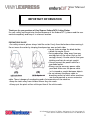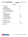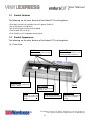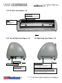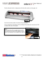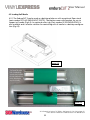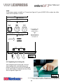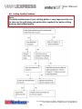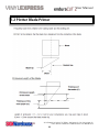
1
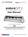
User Manual
User Manual
https://www.signwarehouse.com/blog-support/
NOTICE
SignWarehouse Inc. reserves the right to modify the information contained in this
user manual at any time without prior notice; un-authorized modification, copying
distribution or display is prohibited. All comments, queries or
suggestions concerning this manual please consult with your local dealer.
2614 Texoma Drive Denison, TX 75020 • 980 Contract St. Suite 110 Lexington, KY
Phone: 903-462-7700 or toll free 800-899-5655 • Fax: 800-966-6834
1
User Manual
IMPORTANT INFORMATION
Thank you for your purchase of Vinyl Express EnduraCUT2 Cutting Plotter.
For your safety and to optimize the performance of the EnduraCUT 2, please read the user
manual completely and keep it in a correct location.
PRECAUTIONS IN USE
• For safety concern, please always hold the cutter firmly from the bottom when moving it.
Do not move the cutter by clasping the depression area on both sides.
• Do not shake or drop the blade holder,
a blade tip maybe fly out.
• During operation, keep away from any
moving parts of the cutter (such as the
carriage, drums). Also be careful that your
clothing and hair do not get caught.
• Always connect the power cable to a
grounded outlet.
• Always use the accessory power cable
provided. Make sure the power cable
isn’t crimped or caught between objects.
• Do not connect the power cable to
branching outlet to which other machines
are also connected, or use an extension
cable. There is danger of overheating and of misoperation of the machine.
• Keep the tools away from children where they can reach.
• Always put the pinch rollers within position of the white marks.
2614 Texoma Drive Denison, TX 75020 • 980 Contract St. Suite 110 Lexington, KY
Phone: 903-462-7700 or toll free 800-899-5655 • Fax: 800-966-6834
2
User Manual
Contents
1. General Information
Page
1.1 Introduction
5
1.2 Package Items
5
1.3 Product Features
6
1.4 Appearance of EnduraCUT 2
6
1.4.1 Front View of EnduraCUT 2
6
1.4.2 Rear View of EnduraCUT 2
7
1.4.3 The Left-hand Side of EnduraCUT 2
7
1.4.4 The Right-hand Side of EnduraCUT 2
7
2. Installation
2.1 Precautions and Notices
8
2.2 Desktop Roller Brackets
9 10
2.3 Blade Installation 11 - 13
2.4 Cable Connections
14
2.5.1 USB Driver Installation
14 - 15
2.6 LXI Software Installation 15 - 18
2.7 USB Driver Un-installation 20
2.8.1 Serial RS-232 Communication
20
2.8.2 Data Transmitting 3. The Control Panel
3.1 The LCD Panel Functions
21
3.2 Menu in On-line Mode
22
3.3 Menu in Off-line Mode
23 - 24
3.4 Menu Items
25 - 29
Continued on page 4...
2614 Texoma Drive Denison, TX 75020 • 980 Contract St. Suite 110 Lexington, KY
Phone: 903-462-7700 or toll free 800-899-5655 • Fax: 800-966-6834
3
User Manual
Contents Cont’d
4. Operation
4.1 Media Loading
4.1.1 Loading the Sheet Media
4.2 Loading the Roll Media 4.3 Optimizing Tracking
4.4 Cutting Force and Offset Adjustment
4.4 When Completing the Cutting Job
5. Maintenance
5.1 Cleaning the cutting Plotter
5.2 Cleaning the Grit Rollers 5.3 Cleaning the Pinch Rollers 6. Trouble Shooting 6.1 Non-Operational Problems
6.2 Operational Problems
6.3 Cutting Plotter - PC Communication Problems
6.4 Software Problems
6.5 Cutting Quality Problems
7. Plotter and Blade Specifications
7-1 Specifications of EnduraCUT 2
7-2 Plotter Blade Primer
30
30 - 31
32 - 33
33
34 - 35
35
36
36
37
38
39
40
41
42
43
44
2614 Texoma Drive Denison, TX 75020 • 980 Contract St. Suite 110 Lexington, KY
Phone: 903-462-7700 or toll free 800-899-5655 • Fax: 800-966-6834
4
User Manual
Chapter 1: General Information
1.1 Introduction
EnduraCUT 2 cutting plotters have been designed to produce computer-generated images
on sheets or rolls of vinyl media.
This manual covers the Vinyl Express EnduraCUT 2 series cutting plotter:
acceptable media widths range from 2.76”(70mm) ~ 28.3”(719mm)
1.2 Package Items
The EnduraCUT 2 is shipped with the items listed below. Please check your package carefully. If you find any item missing, please consult SignWarehouse customer service for further
assistance.
Standard Item
1. Cutting Plotter
2. Stand Set ( Optional )
• 1 Left side vertical stand
• 1 Right side vertical stand
• 1 Support for left side
• 1 Support for right side
• 1 Stand Beam
• 2 Bottom Stands with wheels
• 2 Sliding brackets for paper takeup
• 1 Hex Wrench (M5) 4
• 28 Socket flat head screws(M6*12L)
• 1 Installation Guide
Quantity
1
1
3. Accessories
• 1 AC power Cord
• 1 USB Printer cable
• 1 Serial cable
• 1 Blade Holder Assembly (Installed in tool carriage of the cutting plotter )
• 1 Blade (Installed in Blade Holder)
• 1 Safety Blade
• 1 Cutting Pad
• 1 Pair of Tweezers
• 1 Roller Tray
2614 Texoma Drive Denison, TX 75020 • 980 Contract St. Suite 110 Lexington, KY
Phone: 903-462-7700 or toll free 800-899-5655 • Fax: 800-966-6834
5
User Manual
1.3 Product Features
The following are the main features of the EnduraCUT 2 cutting plotter:
• Dual-port connectivity provides you with greater flexibility.
• Up to 400-gram cutting force.
• Up to 600mm/per second cutting speed.
• Guaranteed 16ft tracking.
• User-friendly, multi-language control panel
1.4 Product Appearance
The following are the main features of the EnduraCUT 2 cutting plotter:
1.4.1 Front View
Grid Drums
move the media back and forth
during operation.
Control Panel
14 buttons and 1 LED and 1 LCM
showing messages and menus.
Slicer Groove
cuts off the extra media easily
along this groove
Tool Carriage
Fig 1-1
performs the cutting with
the blade or pen.
Platen
provides the surface for
supporting media while
cutting.
Alignment Rulers
media can be aligned with
the clear guide line marks.
Cutting Pad
provides the protection of
blade when the blade is
cutting.
2614 Texoma Drive Denison, TX 75020 • 980 Contract St. Suite 110 Lexington, KY
Phone: 903-462-7700 or toll free 800-899-5655 • Fax: 800-966-6834
6
User Manual
1.4.2The Rear View (Figure 1-2)
Pinch Rollers
Holds the media during cutting
Lever
raises or lowers the
pinch rollers.
Fig 1-2
1.4.3The Left-Side View (Figure 1-3)
Fuse -3Amp.
1.4.4Right-Side View (Figure 1-4)
Fig 1-3
USB Connector
AC Power Connector
Fig 1-4
Used to connect the cutting plotter to a
computer through a USB cable.
Power Switch -On
when switches to [I]; Off
to [O].
Serial Interface Connector (RS232C)
Used to connect the cutting plotter to a computer
through a serial interface cable.
2614 Texoma Drive Denison, TX 75020 • 980 Contract St. Suite 110 Lexington, KY
Phone: 903-462-7700 or toll free 800-899-5655 • Fax: 800-966-6834
7
User Manual
Chapter 2: Installation
2.1
Precautions
Notice 1
• Carefully handle the cutter to prevent any injuries.
• Make sure the power switch is off before installing the cutting plotter.
Notice 2 A proper place for installation the cutting plotter
Please select a proper location that meets the following conditions:
• The machine can be approached easily from any direction.
• Keep at least 2feet (60 cm) of clear space in front and behind the machine.
• Make sure the cutter is placed on a flat, level and sturdy surface
• The operation temperature should be between 60° and 86°F (15° to 30°C) in the workshop.
• The relative humidity of the working environment should be between 25% to 75%.
• Protect the machine from dust and air current.
• Prevent the machine from direct sunlight.
Notice 3
Connecting the Power Supply
Check the plug of the power cord to see if it matches the wall outlet. If not, please contact your dealer.
• Insert the plug (male) into a grounded power outlet.
• Insert the other end (female) of power cord into the AC connector of cutting plotter.
2614 Texoma Drive Denison, TX 75020 • 980 Contract St. Suite 110 Lexington, KY
Phone: 903-462-7700 or toll free 800-899-5655 • Fax: 800-966-6834
8
User Manual
2.2
Desktop Roller Brackets
Step 1
Check three spacer supports on the back of the machine.
Figure 2-1
Step 2
Insert the left and right roll holder base into the spacer supports
on the left and right side when 2 inches roll media is used.
Figure 2-2
2614 Texoma Drive Denison, TX 75020 • 980 Contract St. Suite 110 Lexington, KY
Phone: 903-462-7700 or toll free 800-899-5655 • Fax: 800-966-6834
9
User Manual
Step 3
Press the roll holder base and the installation is complete.
Figure 2-3
Note: Insert the left roll holder base into the middle spacer support
and right roll holder base into the right one when 1 inches roll
media is used.
Figure 2-4
2614 Texoma Drive Denison, TX 75020 • 980 Contract St. Suite 110 Lexington, KY
Phone: 903-462-7700 or toll free 800-899-5655 • Fax: 800-966-6834
10
User Manual
2.3 Blade Installation
Caution!
• Do not touch the tip of the blade with your fingers!
Notice!
The blade is a consumable item, which will affect the cutting quality significantly. Please replace with
a new blade when having the following situations:
1. The tip of blade is broken.
2. The cutting traces are not as good as they were.
3. Uncut area remains the same even the blade force has been raised significantly
Figure 2-5 is the picture of the blade holder. Insert a blade into the bottom of the blade holder.
Pushing the pin on the top of blade holder can remove the blade. Be sure to keep your fingers away
from the blade tip.
Pin
Blade Depth Adjustment
Knob
Outer Ring
Figure 2-5
2614 Texoma Drive Denison, TX 75020 • 980 Contract St. Suite 110 Lexington, KY
Phone: 903-462-7700 or toll free 800-899-5655 • Fax: 800-966-6834
11
User Manual
2.3 Blade Installation
1: Install Blade. (Figure 2-6)
Figure 2-6
2: Push the blade to the bottom of the blade holder. (Figure 2-7)
Figure 2-7
3. Adjust the blade tip to suitable length by rotating “Blade depth adjustment screw” clockwise or
counterclockwise. (Figure 2-8)
Tips:
“The proper length” means the
blade length is about 0.1mm more
than film’s thickness. For example,
if the thickness of film is 0.5mm,
then the blade length is properly
adjusted to 0.6mm and it can
completely cut through the film
layer without cutting though the
paper backing.
Figure 2-8
2614 Texoma Drive Denison, TX 75020 • 980 Contract St. Suite 110 Lexington, KY
Phone: 903-462-7700 or toll free 800-899-5655 • Fax: 800-966-6834
12
User Manual
4. Insert the blade holder into tool carriage. Please note the outward ring of the holder must put
into the groove of carriage firmly (Figure 2-9) and lock the grip. (Figure 2-10)
Figure 2-10
Figure 2-9
5. Reverse steps mentioned above to remove the blade holder.
6. Press the push-pin to remove the blade from the blade holder when replacing blade. (Figure 2-11)
Figure 2-11
2614 Texoma Drive Denison, TX 75020 • 980 Contract St. Suite 110 Lexington, KY
Phone: 903-462-7700 or toll free 800-899-5655 • Fax: 800-966-6834
13
User Manual
2.4 Cable Connectioins
The EnduraCUT 2 communicates with a computer through USB (Universal Serial Bus) or Serial port
(RS-232C). This chapter shows you how to connect the cutting plotter to a host computer and how
to set up the computer/cutting plotter interconnection.
NOTE! When the USB connection is enabled, the serial port is automatically disabled.
Serial Port
USB Port
Figure 2-12
2.5.1 USB Driver Installation
EnduraCUT 2 built-in USB interface is based on the Universal Serial Bus Specifications Revision 1.1
(Not compatible with Windows 95 Windows NT Operating Systems ).
NOTE!
If you are using Windows 2000 ,Vista, 7 or 8 as your operating system, make sure you log in as
an “Administrator”when installing the USB driver. Administrative privileges are required.
If you have difficulty installing the USB driver, you may need to temporarily disable or uninstall
anti-virus software. Once the USB driver installation is complete, reactivate or reinstall your
anti-virus software. and make sure it recognize the new driver as an approved device
Use the USB One-click Installation for quick driver installation. Follow the simple steps below for
driver setup.
2614 Texoma Drive Denison, TX 75020 • 980 Contract St. Suite 110 Lexington, KY
Phone: 903-462-7700 or toll free 800-899-5655 • Fax: 800-966-6834
14
User Manual
USB Driver Installation Cont’d
Connecting the plotter
1. Turn on the machine.
2. Connect the USB connector to the machine and then USB driver will installed
automatically. It will take a few minutes to find the device. Please DO NOT disconnect
the USB cable until the installation has completed.
3. You can double click the USB icon on the taskbar to make sure the USB device is
detected (Fig 2-13).
Figure 2-13
2.6 LXI Cloud Software Installation
Before you can proceed using your cutter, you need to install LXi software that you purchased with the EnduraCUT 2. You’ll find complete step-by-step instructions on our Tech
support Blog. Please click here to access the setup tutorial (Fig 2-13a) or surf to
http://www.signwarehouse.com/blog-support/getting-started-with-cloud-2/
Figure 2-13a
2614 Texoma Drive Denison, TX 75020 • 980 Contract St. Suite 110 Lexington, KY
Phone: 903-462-7700 or toll free 800-899-5655 • Fax: 800-966-6834
15
User Manual
2.6 Setting up Your EnduraCUT 2 In LXI
1: Turn plotter on and connect USB port to your PC.
2: Then Open LXI software, draw a box or add text to the screen and click the Cut/Plot
Icon, or click File/Cut-Plot to open the LXI Cut/Plot Window. When Production Manager
opens, click Setup. Then from the drop-down menu, click Add Setup (Fig 2-14)
Figure 2-14
3: In the Add Setup window, you will be prompted to “choose a device” (Fig 2-15).
First you must choose a brand, then choose the model of your plotter. Click the top bar
to open the Brand drop-down menu. If you are going to use the USB
connection, click to select Vinyl Express as the brand
From the model drop-down list, click to select EnduraCUT 2S (Fig 2-16).
Figure 2-15
Figure 2-16
2614 Texoma Drive Denison, TX 75020 • 980 Contract St. Suite 110 Lexington, KY
Phone: 903-462-7700 or toll free 800-899-5655 • Fax: 800-966-6834
16
User Manual
4: After you have selected the make and model of the cutter, click Next at the bottom of the
Add Setup window. The next screen in the Add Setup window will prompt you to choose a
port by asking “How is your enduraCUT 2S connected to your computer?”. Click the arrow to
show the drop-down menu (Fig 2-18) and, from the list of ports, choose USB_Printer_1 .
Figure 2-18
5: Now that you’ve added the plotter to your LXI Production Manager, you need to perform
a test cut to make sure the printer port you’ve selected is the one to which the plotter is actually connected to your PC. Most PCs have more than one USB port, so you may have selected a port other than the one to which you’ve connected the plotter.
To test this, right click on “EnduraCUT 2S” in Production Manager. From the drop-down
menu, click Test Cut (Fig 2-19). This will send a cut command to the plotter. If it responds and
cuts a square pattern, you have completed the setup and are ready to use the plotter.
NOTE: Make sure the cutter is turned on, online, and has vinyl loaded before proceeding.
Figure 2-19
2614 Texoma Drive Denison, TX 75020 • 980 Contract St. Suite 110 Lexington, KY
Phone: 903-462-7700 or toll free 800-899-5655 • Fax: 800-966-6834
17
User Manual
6: If the plotter did not respond to the test cut (or if some other device was activated, you
must change the port setting to the correct one for the plotter (or connect the plotter to a
different USB port).
To change the USB port setting, right-click on “enduraCUT2S _USB_Printer_1” (just above
“EnduraCUT2S”. From the pop-up menu, select Change Port (Fig 2-20). Then, from the menu
of available ports, select a different USB printer port (Fig 2-21). Repeat the Test Cut process,
making sure that the cutter is turned on and online. Once you have sucessfully performed a
Test Cut, you are ready to use your cutter to create vinyl graphics.
Figure 2-20
Figure 2-21
2614 Texoma Drive Denison, TX 75020 • 980 Contract St. Suite 110 Lexington, KY
Phone: 903-462-7700 or toll free 800-899-5655 • Fax: 800-966-6834
18
User Manual
2.7.1 USB Driver Un-Installation
If you have to un-install the USB driver after it has been installed on your PC, or if you need
to install a newer version, the existing driver must be removed completely before you can
re-nstall the current driver or install a newer version. Please refer to below steps
1: Click the Windows Start button and open the Devices and Printers folder. Right-click on
the printer (EnduraCUT 2 or Expert-Pro 60) and, from the drop-down menu, click Delete.
You will be promoted to confirm that you actually want to delete the printer. (Fig 2-22)
Click yes.
2: After removing the unit, right click on any
empty space on the page and select “Server
Property” (Fig 2-23).
Figure 2-22
Figure 2-23
2a: If you don’t see the Server Properties
on the pop-up menu, select an installed
printer to highlight it and look at the top
menu bar (Fig 2-24).
3: From the Print Server Properties window, click on the Drivers tab. (Fig 2-25).
Figure 2-24
Figure 2-25
2614 Texoma Drive Denison, TX 75020 • 980 Contract St. Suite 110 Lexington, KY
Phone: 903-462-7700 or toll free 800-899-5655 • Fax: 800-966-6834
19
User Manual
4: Find the Expert Pro 60 in the list of print
devices, click to highight it, then click Remove
and OK (Fig 2-26).
Figure 2-26
5: You will be asked to remove the driver only or the driver and package. Select
Remove Driver Only, then click Yes to
confirm (Fig 2-27). This will completely
remove the USB driver from your PC.
Figure 2-27
2.8.1 Serial RS-232 Communication
1) For Personal Computer users, connect the RS-232C cable to the serial connector of the
assigned serial port (COM1 or COM2) on your host computer.
2) Set up the communication parameters (Baud Rate and Data Bits/Parity) to match the setting of software package, refer to chapter 3 – “MISC” key description
Caution!! Please turn off the plotter before plugging the RS-232C cable
2.8.2 Data Transmitting
There are two options to transmit the data from the computer to the cutting plotter:
Option 1: With proper interface settings, the data can be transmitted from your application
software package to the cutting plotters directly.
Option 2: Most cutting software packages are able to emulate HP-GL or HP-GL/2 commands,
Therefore, you can send graphic files directly from applications like CorelDRAW or Adobe
Illustrator by using the File/PRINT command. As long as the file is HP-GL or HP-GL/2 format,
the cutting plotter can output the data precisely
2614 Texoma Drive Denison, TX 75020 • 980 Contract St. Suite 110 Lexington, KY
Phone: 903-462-7700 or toll free 800-899-5655 • Fax: 800-966-6834
20
User Manual
Chapter 3: The Control Panel
This chapter describes the operation of the EnduraCUT 2 control panel and the navigation
of the menu. When the cutting plotter is ready for use as described in Chapter 1 & 2, all
functions are under default parameters.
3.1 The Control Panel
EnduraCUT 2 LCD Control Panel Functions
Key
LCD Screen
Power LED
4 Arrow Keys
ENTER
PAUSE/RESUME
ON/OFF LINE
OFFSET
FORCE
SPEED
CUT TEST
DATA CLEAR
TOOL SELECT
MISC
Function
To display functions and error messages.
To indicate the power status ( light up: power on; light off: power off )
To move blade holder or media, select functions, or change settings.
To set item or register the immediately preceding input value.
To temporarily halt or continue cutting process
To switch modes, stop cutting job, or abort setting changes.
To adjust the value of blade’s offset.
To adjust the value of cutting force.
To adjust the value of cutting speed and quality.
To perform cutting tests on different media.
To clear buffer memory.
To select tools.
To set up functions.
2614 Texoma Drive Denison, TX 75020 • 980 Contract St. Suite 110 Lexington, KY
Phone: 903-462-7700 or toll free 800-899-5655 • Fax: 800-966-6834
21
User Manual
3.2 Menu in On-Line Mode
Power On EnduraCUT 2 in processing
2614 Texoma Drive Denison, TX 75020 • 980 Contract St. Suite 110 Lexington, KY
Phone: 903-462-7700 or toll free 800-899-5655 • Fax: 800-966-6834
22
User Manual
3.3 Menu in Off-Line Mode
Press [ON/OFF LINE] to switch to Offline Mode
2614 Texoma Drive Denison, TX 75020 • 980 Contract St. Suite 110 Lexington, KY
Phone: 903-462-7700 or toll free 800-899-5655 • Fax: 800-966-6834
23
User Manual
2614 Texoma Drive Denison, TX 75020 • 980 Contract St. Suite 110 Lexington, KY
Phone: 903-462-7700 or toll free 800-899-5655 • Fax: 800-966-6834
24
User Manual
3.4 Menu Items
The Table below desribes the fucnctions of EnduraCUT 2 Menu Commands
Menu or Key
Function
Setting
Default
--- MEDIA SIZING --Roll
To measure media width.
Maximum Tracking 150
meters
Edge
To measure media width and pull the media back untill the front
paper sensor is uncovered.
Maximum Tracking 150
meters
Single
To measure media width and length.
Maximum Tracking 10
meters
--- POWER --To indicate the power status.
[ARROW KEYS]
1. To move the tool carriage position on X or Y axis.
2. To select functions or change values of settings.
[ENTER]
1. The displayed parameters will be saved automatically.
2. To set a new origin at the present tool carriage position.
In “offline” mode, moving the tool carriage to desired position by
[Arrow Keys], then press [ENTER] key to set a new origin. While
moving with the parameters of XY-axes displayed, pressing [MISC]
key will enable fine-tune movement; pressing [MISC] key again
will disable the function.
[Pause/Resume]
To temporarily halt the cutting process.
To resume the process, press [Pause/Resume] key again.
[ONLINE / OFFLINE]
1. To switch between online mode and offline mode.
2. To stop the cutting job or abort the change of setting.
Once this key is pressed, the cutting job will be halted immediately
and cannot be resumed.
[OFFSET]
To set or modify the distance between the blade tip and the center
axis.
0.000~1.000mm
0.275mm
5~400gram;
per step
80 gram
[FORCE]
To set or modify the amount of cutting force.
5 gram/
Continued Next Page...
2614 Texoma Drive Denison, TX 75020 • 980 Contract St. Suite 110 Lexington, KY
Phone: 903-462-7700 or toll free 800-899-5655 • Fax: 800-966-6834
25
User Manual
3.4 Menu Items Cont’d
Menu or Key
Function
Setting
Default
51cm/
sec
51cm/
sec
[SPEED]
Speed
To set or modify horizontal speed of the tool carriage .
3~60cm/sec; 3cm/sec
per step
Up Speed
To set or modify vertical speed of the tool carriage.
3~60cm/sec; 3cm/sec
per step
Single
To measure media width and length.
Maximum Tracking 10
meters
Cutting Quality
To set or modify cutting quality.
[Slower speeds / higher quality - Faster speeds / lower quality]
Draft, Normal, Fair, Fine
Normal
The Set Cutting Quality Page allows you to adjust and balance
vector mode’s quality and speed settings based on your specific
job. Draft Mode offers the highest output speed, sacrificing quality.
Quality Mode offers the highest quality, sacrificing output speed.
Keep in mind that speed and quality are usually a tradeoff.
[ CUT TEST ]
Square Cut
To perform a cutting test at present blade position.
For more information, please refer to “4.3 Adjusting the Cutting
Force and Offset” to adjust blade force and cutting speed.
Redo Last Plot
Recut:
To repeat the last job without re-sending the data.
Copy:
To copy the last job without re-sending the data.
1~99;
1 per step
1~99;
1 per step
* 1mm gap will be auto-generated between 2 copies).
* If the media length is not enough to continue, it will show
the LCM will display the message below:
Ou t O f S p a c e ;
#
o f C o p i e s f i n i s h e d
If both functions are enabled at the same time, the cutter will perform the last setting only
Pattern Setting
To provide two patterns for cut test
Note: It is recommended to select “Cross” if you are working on
thick pieces of materials.
“Arrow” and “Cross”
patterns
“Arrow”
Ratio Setting
To adjust the size of the pattern
100%, 200%, 300%,
400%
100%
Continued Next Page...
2614 Texoma Drive Denison, TX 75020 • 980 Contract St. Suite 110 Lexington, KY
Phone: 903-462-7700 or toll free 800-899-5655 • Fax: 800-966-6834
26
User Manual
3.4 Menu Items Cont’d
Menu or Key
Function
Setting
Blade Length
Adjust
To adjust the length of the blade
0.00mm-5.00mm
Note:
1.
Keep your blade length as 0 before you start adjusting.
2.
Test the blade holder first and then test the blade length by
pressing ENTER.
3.
Keep the blade holder at the same position when you
perform blade holder and blade length tests.
4.
When blade holder and blade length tests are finished, the
screen will show you to what degree (the unit of the value following
“CW” or “CCW” is “circle”) and in which direction [CW (clockwise) or CCW (counterclockwise)] you should turn the adjustment
knob. I.E. “Turn CW 0.5” means you should turn the knob clockwise one half turn.
5.
The value on the screen will be 0.0 when the blade length
is perfect and no more adjustment needs to be made. You may start
cutting at this point.
Default
0.00mm
[ DATA CLEAR ]
To clear buffer memory.
[ TOOL SELECT ]
Enable
Set Smoothing
Cut
To enable smooth-cutting function.
Over Cut
To generate an overcut to facilitate weeding.
Set Tangential
Mode
To enable the emulated tangential-cutting mode for thicker media
types and small letter cuts.
Note: If the Offset value is set at 0.000 mm, “Set Tangential Mode”
will automatically be disabled.
Panel Setup
Accept setup command:
To accept commands of the Force, Speed, Cutting Quality, and
Offset only from software.
0.00mm-1.00mm
0.05mm/per step
0.00mm
Disable
Control panel only:
To accept commands of the Force, Speed, Cutting Quality, and
Offset only from the control panel of the cutter.
Restore Default
To return all parameters of the menu items to factory-default
settings.
Continued Next Page...
2614 Texoma Drive Denison, TX 75020 • 980 Contract St. Suite 110 Lexington, KY
Phone: 903-462-7700 or toll free 800-899-5655 • Fax: 800-966-6834
27
User Manual
3.4 Menu Items Cont’d
Menu or Key
Function
Setting
Default
Save Parameter
To save pattern(s) of cutting parameters for later use.
There are 4 sets of parameters saved in the panel. Use Page Up and
Page Down keys to select the set of parameters you wish to adjust,
press “Enter” to confirm (the number shown on the upper left
corner will change accordingly). Each set of parameters includes
Speed, Force, Offset, Up Speed, Quality and Scaling, although the
latter three will not be displayed in this section. To adjust or check
individual parameters, go back to the responding keys on the panel
and press “Enter” to confirm.
Auto Unrolled
Media
To avoid paper jam and motor crash by automatically unroll media
(50cm and up) before cutting while enabled.
* Auto-unroll is only active on roll or edge media settings.
* Using Single mode to size media will disable this function automatically.
* If the length of the rolled media is less than 2 meters or the roll
weight is light, it is recommended to disable this feature.
Disable
Rear Paper
Sensor
Enable
To detect if the rear paper sensor is covered to determine the
Disable
following process; when it is enabled, the cutter will detect if the
material has covered the rear paper sensor under the Roll and Edge
mode; when disabled, the rear paper sensor will not function.
Note: Rear paper sensor only functions under “Roll” and “Edge”
media settings.
Enable
Vacuum
To help improve tracking and cutting accuracy by turning on the
fans. If you turn off the vacuum system, the fans will remain inactive during cutting or plotting.
Enable
Paper Saving
Mode
To save media by four different modes:
1. Length expanded mode 2. Width expanded mode
3. Both expanded mode 4. Both unexpanded mode
Both
unexpanded
mode
Set Communication
To speed up the communication between host computer and cutter.
Baud Rate determines the speed of data transmission. Data Bits
refers to the size of one block of data.
Parity is used to check if data was revived correctly or not.
[ MISC ]
9600, n, 7, 1, p
9600, o, 7, 1, p
9600, e, 7, 1, p
9600, n, 8, 1, p
9600, o, 8, 1, p
9600, e, 8, 1, p
19200, n, 7, 1, p
19200, o, 7, 1, p
9600pbs, 7 Bits with NO Parity
9600pbs, 7 Bits with ODD Parity
9600pbs, 7 Bits with EVEN Parity
9600pbs, 8 Bits with NO Parity
9600pbs, 8 Bits with ODD Parity
9600pbs, 8 Bits with EVEN Parity
19200pbs, 7 Bits with NO Parity
19200pbs, 7 Bits with ODD Parity...
Continued Next Page...
2614 Texoma Drive Denison, TX 75020 • 980 Contract St. Suite 110 Lexington, KY
Phone: 903-462-7700 or toll free 800-899-5655 • Fax: 800-966-6834
28
User Manual
3.4 Menu Items Cont’d
Menu or Key
Function
Setting
Default
[ MISC ]
19200, e, 7, 1, p
19200, n, 8, 1, p
19200, o, 8, 1, p
19200, e, 8, 1, p
19200pbs, 7 Bits with EVEN Parity
19200pbs, 8 Bits with NO Parity
19200pbs, 8 Bits with ODD Parity
19200pbs, 8 Bits with EVEN Parity
Firmware
Version
To display the version number of Firmware and FPGA code.
Select Language
To select displayed languages on LCM panel in English, Spanish,
Italian, Deutsch, Japanese, Portuguese, Polish, Turkish or French.
Select Units
Provide four-unit systems for user convenience.
Image Scale
Length
To adjust the image scale of media length and width that may be
caused by the thickness of the media.
English
cm/gram; inch/oz;
cm/oz; inch/gram
Metric
500/500 mm
The Numerator is the ideal length, and the Denominator is the
actual length measured from the result.
Image Scale
Width
For example, cutting a line with 500.0 mm length. The procedure as
follows:
1. Press the [LEFT ARROW] to choose the Numerator and
select 500.0 mm,
2. Cut the length by sending a graph file,
3. Measure the length then use the [RIGHT ARROW] key to
choose the Denominator, then
4. Press [UP ARROW /DOWN ARROW] to change the values of
the actual length.
Scale Length
Fixed scaling, for maintenance only.
Scale Width
2614 Texoma Drive Denison, TX 75020 • 980 Contract St. Suite 110 Lexington, KY
Phone: 903-462-7700 or toll free 800-899-5655 • Fax: 800-966-6834
29
User Manual
Chapter 4: Operation
4.1 Media Loading
4.1 Loading Sheet Media
To load the media properly, please follow the procedures listed below:
Pull the lever upward to raise the pinch rollers. (Figure 4-1)
Rear paper sensor
Figure 4-1
Load your media on the platen and slide it under the pinch rollers from either the front side
or the back. The alignment rulers on the platen extension will help you to adjust the media
precisely so that it is loaded straight and will track correctly through the plotter.
Note:
Be sure that the the paper sensors are covered by the media when
loading the media. At least one of the two paper sensors should be
covered. Once the media covers the sensor, the cutting plotter will size
width and length of media automatically.
Then move the pinch rollers manually to the proper position. Be sure to position the pinch
rollers above the grid drum. The white marks on top rail indicate the position of the grit
rollers. Align the pinch rollers with these marks to ensure they are positioned above the grit
rollers. This provides friction and pressure on the top and bottom of the media to ensure
proper tracking (Figure 4-2, next page).
2614 Texoma Drive Denison, TX 75020 • 980 Contract St. Suite 110 Lexington, KY
Phone: 903-462-7700 or toll free 800-899-5655 • Fax: 800-966-6834
30
User Manual
Position the pinch rollers in alignement with the white markers on the upper rail.
Figure 4-2
Push the lever downward to lower down the pinch rollers.
Turn on the power; the machine will be initialized. Then follow the instruction of LCM
to measure the size of the media.
Note:
Move the pinch roller by applying force at the
rear portion of the pinch roller support. Do not
move it by holding its front rubber roller (Fig 4.3).
Figure 4-3
2614 Texoma Drive Denison, TX 75020 • 980 Contract St. Suite 110 Lexington, KY
Phone: 903-462-7700 or toll free 800-899-5655 • Fax: 800-966-6834
31
User Manual
4.2 Loading Roll Media
4.2.1 The EnduraCUT 2 can be used as a desktop plotter or with an optional floor stand
(part number PLTA-VE-ENDURACUT-2S-STD). The plotter comes with brackets for use to
support roll media (Fig 4.4). An optional roller tray (Part number SE-ES-ENDURATRAY) is
also available and is a better solution for controlling rolls of media in a desktop configuration (Fig 4.5).
Figure 4-4
The EnduraTray holds
rolls of media more
securely than the brackets that come with the
cutter, allowing the
vinyl to roll freely.
Figure 4-5
2614 Texoma Drive Denison, TX 75020 • 980 Contract St. Suite 110 Lexington, KY
Phone: 903-462-7700 or toll free 800-899-5655 • Fax: 800-966-6834
32
User Manual
4.2.2 After loading the media on the brackets, roller tray, or stand, pull the front edge forward under the pinch rollers.
1. Pull it toward the front edge of the platen and use the ruler to check alignment. The side
edges of the media should be perpendicular to the front of the plotter.
2. After loading the roll media, flatten the media on the platen and hold the front edge of
the roll media firmly to ensure that the roll is straight.
3. Move the pinch rollers to the precise location and be careful that the pinch rollers are
positioned above the grit rollers (under the white marks).
6. Push the lever downward to lower the pinch rollers.
7. Turn on the power switch, and the tool carriage will size the media automatically. Then
the cutting plotter is ready to work.
8. Unloading media: Reversing steps mentioned above to remove the media.
4.3 Optimizing Tracking
In order to achieve the best tracking performance for a long plot, please leave the margin
of 0.5mm~25mm in the left and right edges of the media. (Figure 4-6)
Figure 4-6
2614 Texoma Drive Denison, TX 75020 • 980 Contract St. Suite 110 Lexington, KY
Phone: 903-462-7700 or toll free 800-899-5655 • Fax: 800-966-6834
33
User Manual
4.4 Cutting Force and Offset Adjustment
Before sending your designs from computer to EnduraCUT 2 for cutting, please make “Cut Test” to
adjust cutting force and offset value.
The “Cut Test” should be repeated several times until the optimum settings are achieved.
Please follow procedure below to optimum the cutting force and offset settings.
Step1.
After sizing the media, press [CUT TEST] button to select the “Square Cut”, and press [ENTER KEY]
to confirm.
The default cutting force and offset value of the cutting test are 80gf and 0.275mm respectively.
Step2.
Press [ARROW KEY] to move the tool carriage to the position where you would like to cut. Then,
press the [ENTER KEY] to make a “Cut Test”.
Note: At the same time, the new origin is also set at the cut test position.
Step3.
When the “Cut Test” is completed, a pattern appears (please refer to Figure 4-7). Peel off the
pattern to see if it can be easily separated from the media base. If the output result is good, the
cutting force is set appropriately. The desired result is a cut throught the vinyl and adhesive and a
very light scoring of the release liner. The vinyl should be easy to remove from the liner.
If the cut vinyl cannot be easily removed from the liner, or if the release liner has also be cut, press
[FORCE KEY] to adjust the tool force until an optimum force is obtained.
Cont’d next Page...
2614 Texoma Drive Denison, TX 75020 • 980 Contract St. Suite 110 Lexington, KY
Phone: 903-462-7700 or toll free 800-899-5655 • Fax: 800-966-6834
34
User Manual
Step4.
If the pattern appears to be BB or CC layout (see Figure 4-7), press [OFFSET KEY] to adjust the offset
value until AA pattern is shown.
S q u a r e
C u t
S e l e c t :
Mo v e
X :
AA
OK : E n t e r
Press
ENTER_KEY
M
c u t
t e s t
Y :
Press
ENTER_KEY
BB
C o n t i n o u s
N : C A N C E L
CC
Press SPEED_KEY,
FORCE_KEY,
OFFSET_KEY to
setup
or
Press arrow keys to
desired position for
next square cut
S q u a r e
C u t
OK : E n t e r
Press
ENTER_KEY
Press
ENTER_KEY
Finish square cut
Press
CANCEL_KEY
3mm
3mm
80 mm
80 mm
80 mm
Machine
Figure 4-7
4.5 Completing the Cutting Job
After completing the cutting job, raise the
sheet-loading lever, and then remove the
material. You can also cut off the finished job
by the Safe Blade (a standard accessory) along
the knife guide. (Figure 4-8)
Figure 4-8
2614 Texoma Drive Denison, TX 75020 • 980 Contract St. Suite 110 Lexington, KY
Phone: 903-462-7700 or toll free 800-899-5655 • Fax: 800-966-6834
35
User Manual
Chapter 5: Basic Maintenance
This chapter explains the basic maintenance (i.e. cleaning the cutting plotter) required for the
cutting plotter. Except for the below mentioned, all other maintenance must be performed by a
qualified service technician.
5.1: Cleaning the Cutting Plotter
In order to keep the cutting plotter under good condition and best performance, you need to clean
the machine properly and regularly.
Cleaning Precautions
• Unplug the cutting plotter before cleaning.
• Never use solvents, abrasive cleaners or strong detergents for cleaning. They
may damage the surface of the cutting plotter and the moving parts.
Recommended Cleaning Methods
• Gently wipe the cutting plotter surface with a lint-free cloth. If necessary, clean with a damp
cloth or an alcohol-immersed cloth. Wipe with water to rinse off any residue and dry with a soft,
lint-free cloth.
• Wipe all dust and dirt from the tool carriage rails.
• Use a vacuum cleaner to empty any accumulated dirt and media residue beneath the pinch
roller housing.
• Clean the platen, paper sensors and pinch rollers with a damp cloth or an alcohol-immersed
cloth, and dry with a soft, lint-free cloth.
• Wipe dust and dirt from the stand.
5.2: Cleaning the Grit Rollers
• Turn off the cutting plotter, and move the tool carriage away from the area needed to be
cleaned.
• Raise the pinch rollers and move them away from the grit rollers for cleaning.
• Use a bristle brush (a toothbrush is acceptable) to remove dust from the drum surface.
Rotate the roller drum manually while cleaning
(Figure 5-1).
Figure 5-1
2614 Texoma Drive Denison, TX 75020 • 980 Contract St. Suite 110 Lexington, KY
Phone: 903-462-7700 or toll free 800-899-5655 • Fax: 800-966-6834
36
User Manual
5.3: Cleaning the Pinch Rollers
If the pinch rollers need a thorough cleaning, use a lint-free cloth or cotton swab to wipe away
the accumulated dust from the rubber portion of the pinch rollers. To prevent the pinch rollers
from rotating while cleaning, use your finger to hold the pinch rollers in place.
To remove embedded contaminants or persistent dust, use a lint-free cloth or cotton swab
moistened with rubbing alcohol.
Note:
The daily maintenance of your cutting plotter is very important. Be sure
to clean up the grid drum and pinch rollers regularly for better cutting
accuracy and output quality.
2614 Texoma Drive Denison, TX 75020 • 980 Contract St. Suite 110 Lexington, KY
Phone: 903-462-7700 or toll free 800-899-5655 • Fax: 800-966-6834
37
User Manual
Chapter 6: Troubleshooting
This chapter is to help you correct some common problems you may come across. Prior to
getting into the details of this chapter, please be sure that your application environment is
compatible with the cutting plotter
Note:
Before having your cutting plotter serviced, please make sure that the
malfunction is in your cutting plotter, not the result of an interface problem or a malfunction in your computer or a software problem.
Why is the cutting plotter not functioning?
Possible Causes:
6.1 Non-Operational Problems
Check the following first:
• Does the AC power cord plug in properly?
• Does the AC power cord connected to the power connector properly?
• Does the power LED still illuminate?
Solutions:
If the LCM is able to display the message, the cutting plotter should be in a normal condition.
Switch off the cutting plotter and turn it on again to see if the problem persists.
2614 Texoma Drive Denison, TX 75020 • 980 Contract St. Suite 110 Lexington, KY
Phone: 903-462-7700 or toll free 800-899-5655 • Fax: 800-966-6834
38
User Manual
6.2 Operational Problems
Some problems are caused by mechanical failure or failure of a specific operation during
plotting. In such cases, an error message will be displayed on the LCM stating the problem
and suggesting a solution. If the problem still exists after you have performed the recommended solutions, have your cutting plotter serviced.
Error, Check Media
Or Drum or X Motor
Error, Check Media
Or Y Motor
Check Carriage
Sensor or VC Motor
Graph Was Clipped.
Data In Buffer
This message indicates that there might be a problem on
the X axis. Check if the drum is working well and if the
media is well loaded. Correct the problem and re-power
on to reboot system.
This message indicates that there might be an obstruction
to carriage relating to a problem on the Y axis. Correct the
problem and re-power on to reboot system.
This message indicates that the blade up/down sensor malfunction. Re-power on to re-boot system. If the problem
still exists, contact SignWarehouse Technical Support.
This message indicates that the cutting exceeds the cutting
limit. Reload larger media or re-scale the plot to a smaller
size; then press the key followed by the display of LCM to
continue.
2614 Texoma Drive Denison, TX 75020 • 980 Contract St. Suite 110 Lexington, KY
Phone: 903-462-7700 or toll free 800-899-5655 • Fax: 800-966-6834
39
User Manual
6.3 Cutting Plotter/Computer Communication Problems
The messages shown below present problems in relation to cutting plotter/computer
communication.
Communication Error
Setup: MISC. key
Note:
The computer also needs to set up compatible communication parameters to the cutting plotter set up.
HP-GL/2 Cmd. Error
If your cutting plotter does not recognize the HP-GL/2 or
HP-GL commands, please make sure the HP-GL/2 or HP-GL
commands applied to your cutting plotter are used
properly.
2614 Texoma Drive Denison, TX 75020 • 980 Contract St. Suite 110 Lexington, KY
Phone: 903-462-7700 or toll free 800-899-5655 • Fax: 800-966-6834
40
User Manual
6.4 Software Problems
Check the following first:
2614 Texoma Drive Denison, TX 75020 • 980 Contract St. Suite 110 Lexington, KY
Phone: 903-462-7700 or toll free 800-899-5655 • Fax: 800-966-6834
41
User Manual
6.5 Cutting Quality Problems
Note:
The daily maintenance of your cutting plotter is very important. Be sure
to clean up the grid drum and pinch rollers regularly for better cutting
accuracy and output quality.
2614 Texoma Drive Denison, TX 75020 • 980 Contract St. Suite 110 Lexington, KY
Phone: 903-462-7700 or toll free 800-899-5655 • Fax: 800-966-6834
42
User Manual
7.1 EnduraCUT 2 Specifications
Operational Method
Max. Cutting Width
Max. Cutting Length
Max. Tracking
Max. Media Loading Width
Min. Media Loading Width
Acceptable Material Thickness
Number of Pinch Rollers
Motor Drive
Cutting Force
Max. Cutting Speed
Offset
Mechanical Resolution
Software Resolution
Distance Accuracy
Repeatability
Memory Buffer
Interfaces
Type of Command
Control Panel
Dimension (HxWxD) mm
Net Weight
Stand
Power Supply
Power Consumption
Environment Temperature
Environment Humidity
Roller-Type
23.6in (600mm)
164ft (50m)
10ft (3.05m)
28.3in(719mm)
2.76in (50mm)
30 mil (0.8mm)
2
DC Servo Control
400 g
Up to 23.62 ips (600 mm /sec)
0~1.0 mm (with an increase of 0.025 mm)
0.009 mm (0.00035in)
0.025 mm (0.00098in)
±0.254 mm or ±0.1% of move, whichever is greater
±0.1mm up to 5 meters (* certified media)
4MB
USB 2.0 (Full Speed) and Serial (RS-232C)
HP-GL, HP-GL/2
LCD (20 digits x 2 lines), 14 Keys, 1 Power LED
8.67 x34.61x10.16in (220x 879x258mm)
28.6lb (13kg)
Optional
AC 100-240V, 50~60 Hz (auto switching)
Max.110watts
15℃~30℃ / 60℉~86℉ (operating)
25%~ 75% relative humidity (operating)
• Compatible with Windows 2000/ XP/ Vista/ 7/ 8 and MAC OS X 10.4-10.7.
• The specification and data sheet may vary with different materials used. In order to obtain the best output
quality, please maintain the machine regularly and properly.
• SignWarehouse Inc. reserves the right to change the specifications at any time without notice.
• The above listed specification values are effective only when operated with media certified by
SignWarehouse or commonly used in the production of vinyl graphics and sign industry applications.
2614 Texoma Drive Denison, TX 75020 • 980 Contract St. Suite 110 Lexington, KY
Phone: 903-462-7700 or toll free 800-899-5655 • Fax: 800-966-6834
43
User Manual
7.2 Plotter Blade Primer
2614 Texoma Drive Denison, TX 75020 • 980 Contract St. Suite 110 Lexington, KY
Phone: 903-462-7700 or toll free 800-899-5655 • Fax: 800-966-6834
44