1
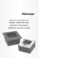
METROLOGIC INSTRUMENTS, INC.
MS860i Mini-Slot™
Laser Bar Code Scanner
Installation and User’s Guide
MLPN 2202
Printed in USA
January 1999
Locations:
USA Corporate Headquarters
Metrologic Instruments, Inc.
90 Coles Road
Blackwood, NJ 08012
Customer Service: 1-800-ID-METRO
Tel: 609-228-8100
Fax: 609-228-6673
[email protected]
www.metrologic.com
Europe
Metrologic Instruments GmbH
Dornierstrasse 2
82178 Puchheim b.
Munich, Germany
Tel: 49-89-89019-0
Fax: 49-89-89019-200
[email protected]
ASIA
Metrologic Asia (PTE) Ltd.
31, Kaki Bukit Road 3
#05-08 Techlink
Singapore 417818
Tel: 65-842-7155
South America
Metrologic Instruments
Rua Flórida, 1.821-5°Andar-Brooklin
CEP 04571-090, São Paulo-SP, Brasil
Outside Brazil:
Tel: 55-11-5505-6568
ii
Table of Contents
Introduction . . . . . . . . . . . . . . . . . . . . . . . . . . . . . . . . . . . . . . . . . . . . . . . . . .
1
Unpacking List . . . . . . . . . . . . . . . . . . . . . . . . . . . . . . . . . . . . . . . . . . . . . . . . . 2
Scanner Connections to the Host . . . . . . . . . . . . . . . . . . . . . . . . . . . . . . . . . . . 3
Configuration of the Scanner to the Host System . . . . . . . . . . . . . . . . . . . . . . 4
Cloning Feature . . . . . . . . . . . . . . . . . . . . . . . . . . . . . . . . . . . . . . . . . . . . . . . . 5
Version 11 IBM 46XX Scanner . . . . . . . . . . . . . . . . . . . . . . . . . . . . . . . . . . .
Configuring the MS860i-11 Scanner . . . . . . . . . . . . . . . . . . . . . . . .
Configuring the IBM 46XX . . . . . . . . . . . . . . . . . . . . . . . . . . . . . . .
IBM 4683 and 4693 Terminals Driven by a 46XX Store
Controller Running 4680.OS or 4690.OS . . . . . . . . . . . .
IBM 4684 and 4694 Systems . . . . . . . . . . . . . . . . . . . . . . . . . . . . . .
6
7
8
8
8
Version 17 Keyboard Wedge Scanner . . . . . . . . . . . . . . . . . . . . . . . . . . . . . . 9
Connection of a MS860i-17 Scanner to a PC . . . . . . . . . . . . . . . . . . . . . . . . 10
Installing the Scanner into a Counter . . . . . . . . . . . . . . . . . . . . . . . . . . . . . . 11
Attaching the Vertical Stand to the Work Surface . . . . . . . . . . . . . . . . . . . . 12
MS860i Features . . . . . . . . . . . . . . . . . . . . . . . . . . . . . . . . . . . . . . . . . . . . . . 13
Touch Plate . . . . . . . . . . . . . . . . . . . . . . . . . . . . . . . . . . . . . . . . . . . . . . . 14, 15
Visual Indicators . . . . . . . . . . . . . . . . . . . . . . . . . . . . . . . . . . . . . . . . . . . 16-19
Volume Settings . . . . . . . . . . . . . . . . . . . . . . . . . . . . . . . . . . . . . . . . . . . . . . . 20
Labels . . . . . . . . . . . . . . . . . . . . . . . . . . . . . . . . . . . . . . . . . . . . . . . . . . . . . .
21
Depth of Field . . . . . . . . . . . . . . . . . . . . . . . . . . . . . . . . . . . . . . . . . . . . . . . . 22
Depth of Field and Symbol Specification . . . . . . . . . . . . . . . . . . . . . . . . 23, 24
iii
Maintenance . . . . . . . . . . . . . . . . . . . . . . . . . . . . . . . . . . . . . . . . . . . . . . . . . . 25
Applications and Protocols . . . . . . . . . . . . . . . . . . . . . . . . . . . . . . . . . . . . .
25
Appendix A
Specifications . . . . . . . . . . . . . . . . . . . . . . . . . . . . . . . . . . . . . . 26, 27
Appendix B
Default Settings . . . . . . . . . . . . . . . . . . . . . . . . . . . . . . . . . . . . . 28-35
Appendix C
Pin Assignments . . . . . . . . . . . . . . . . . . . . . . . . . . . . . . . . . . . . 36-41
Appendix D
Warranty and Disclaimer . . . . . . . . . . . . . . . . . . . . . . . . . . . . . 42, 43
Appendix E
Notices . . . . . . . . . . . . . . . . . . . . . . . . . . . . . . . . . . . . . . . . . . . 44, 45
Appendix F
Patents . . . . . . . . . . . . . . . . . . . . . . . . . . . . . . . . . . . . . . . . . . . . . . . 46
Volume Control Card . . . . . . . . . . . . . . . . . . . . . . . . . . . . . . . . . . . . . . . 47, 48
Index . . . . . . . . . . . . . . . . . . . . . . . . . . . . . . . . . . . . . . . . . . . . . . . . . . . . 49, 50
iv
Introduction
Metrologic's MS860i Mini-Slot™ Laser Bar Code Scanner is a high-speed,
aggressive in-counter scanner. The MS860i unsurpassed scanning accuracy and
incorporates the most advanced laser technology in a smaller, yet rugged and
durable housing. Designed to be used where counter space is at a premium, the
MS860i can be used in a variety of applications.
The MS860i autodiscriminates all standard bar codes, eliminating the need to
"key in" unprogrammed codes increasing productivity and efficiency. A code
correcting feature (MECCA)© enables the MS860i to decode damaged or
truncated codes on the first pass, making the MS860i an excellent choice for
reclamation and coupon redemption applications. Each version of the MS860i
provides three interface options, with full RS-232 protocol available on every
scanner. Three most popular protocols (RS-232, OCIA and Light Pen Emulation)
are consolidated into the standard model. For simple PC connectivity, a keyboard
wedge interface is also available. Metrologic also offers a patented Hand-Held
Option, which allows users to connect the MS941 Hand-Held Scanner to the
MS860i for greater scanning versatility.
The MS860i is easy to program via bar code menus from ScanSelect™ Scanner
Programming Guide or by using Metrologic's ScanSet™ IBM® compatible
software program. Other key features of the MS860i are the auto-off/touch-on
plate and easily visible LED indicators mounted on the brushed stainless steel top
plate. An optional hardened glass window is also available. Universal adaptor
plates make it simple to replace older, larger flatbed scanners with the smaller
MS860i. Metrologic also provides a vertical mounting option, so customers can
use the MS860i as a projection scanner as well.
Most importantly, the MS860i is easy to afford. It offers a superior, versatile and
low cost alternative to larger, more expensive in-counter scanners.
1
Unpacking List
The shipping carton contains the following:
!
Installation and User’s Guide (MLPN: 2202)
ScanSelect™ Scanner Programming Guide (MLPN: 2186)
Volume Control Card (MLPN: 2346)
!
MS860i Laser Bar Code Projection Scanner
!
Installation Plate (MLPN: 45471)
!
Power Supply (optional)
!
Communication cable with connection for power supply (optional) or
Communication Cable (optional)
!
Adaptor Plate or Vertical Stand (optional)
If any item is missing or to order additional items, contact the dealer, distributor
or call Metrologic’s Customer Service Department at 1-800-ID-METRO or 1800-436-3876.
2
Scanner Connections to the Host
To maintain compliance with applicable standards, all circuits connected to the
scanner must meet the requirements for SELV (Safety Extra Low Voltage)
according to EN 60950. To avoid potential problems, do not power up the
scanner until the communication cable is secured to the host.
1. Turn off the host system.
2. Connect the 25-pin D-type connector on the scanner’s head cable to the
communication cable. Connect the other end of the communication cable
to the host device. (If the scanner will not receive power from a
transformer, skip to Step 5.)
3. If the scanner will receive power from an external power source, check the
AC input requirements of the transformer to make sure the voltage
matches the AC outlet. (A socket-outlet shall be installed near the
equipment and shall be easily accessible.)
4. Plug the transformer into the side of the female D-type connector located
on the communication cable. Plug the transformer into the AC outlet to
supply power to the scanner.
5. Power up the host system.
Note: When the scanner first receives power, the LEDs will flash and then
the scanner will beep once. After the scanner performs this start up
sequence, the green LED will remain on for a specified time
indicating that the laser is on.
3
Configuration of the Scanner to the Host System
The scanner is shipped from the factory programmed to a set of default conditions
noted in the Default Settings section of this guide and in the ScanSelect™
Scanner Programming Guide. The default settings in the ScanSelect guide have
an asterisk that appears before the brief definition
next to the bar code.
To communicate with the host system properly, it needs to be programmed to
meet specific scanning needs. Since each host system is unique, configure the
scanner to match the host system requirements. Configure the scanner by entering
program mode and scanning the appropriate bar codes that appear in the
ScanSelect Scanner Programming Guide. (When using ScanSet™, refer to the
ScanSet documentation for information on how to configure the scanner.)
1. Connect the scanner to the host system. (Refer to the Scanner
Connections to the Host section in this guide)
2. Enter program mode by scanning the ENTER/EXIT program mode bar
code as the first bar code after a power up cycle.
(The unit will beep three times.)
3. Scan the appropriate bar code(s) that appear in the ScanSelect Scanner
Programming Guide. (Reveal only one bar code to the scanner each time.
With your hand, cover the bar code that is not to be scanned.)
4. Exit program mode by scanning the ENTER/EXIT program mode bar
code again. (The new options will be saved and the scanner is ready for
normal operation.)
Note: Non-RS-232 interfaces chosen in Section B of the ScanSelect
Programming Guide do not match the default settings that are loaded
when the same interface is selected with ScanSet.
4
Cloning Feature
To program several scanners with the same settings, use the Cloning feature. This
is done by connecting the cloning cable (MLPN: #51544) between two scanners.
1. Turn off both scanners.
2. Connect the cloning cable between the two scanners.
3. Turn both scanners on by plugging in the transformers.
4. Once each scanner is ready, scan the cloning bar code with the scanner
that has the settings that need to be transferred to the other scanner.
5
Version 11 IBM 46XX Scanner
Output Format:
IBM RS-485 serial input/output for the 4680 and 4690
(46XX) point-of-sale terminals
The Version 11 46XX interface can be used in several different ways. Both the
46XX terminal and the scanner must be configured to match each other.
Warning: Power to the scanner and 46XX terminal should be turned off
before making physical connection.
The 4680 and 4690 series terminals have different types of physical ports for
connecting bar code scanners. Scanner ports include Port 5B, Port 17, and Port
9? (? = A, B, C, or E). A Port 9 type connector is present on all versions of the
46XX families of terminals. That is one reason why it is the normal point of
connection for Metrologic scanners. Another reason is that there is enough 12
volt power available to operate many Metrologic scanners. If your terminal
configuration requires the use of a different physical port for connecting bar code
scanners, contact Metrologic to get particular adaptor cable information.
All devices use a common communications bus inside the 46XX terminal, despite
what port that is in use for the physical connection. Each device has a different
address that it uses when it communicates. The terminal must be configured to
look for a device at a logical address.
The IBM 1520 mode/address was selected as a default because it was the first
IBM 46XX family scanner to support UPC/EAN, Code 39 and Interleaved 2 of
5 (I 2 of 5). The Version 11 scanner formats Codabar, Code 128, and Code 93
using the Code 39 function code designation supported by the IBM device driver
for this scanner type. Other emulation modes currently available are the IBM
3687-2 Port 17 fixed scanner and the Port 9B IBM 4500 CCD hand-held bar
code reader. The use one of these other emulation modes may be needed
depending on which operating system (4680.OS, 4690.OS, POS/DOS or
DOS/RIPPS) is in use at your site.
Note:
6
The IBM 4683 and IBM 4684 terminals have a good proven track
record of supplying power to Metrologic scanners. The IBM 4693 and
IBM 4694 terminals may be restricted from supplying power to certain
scanner models. Specifically, Metrologic currently recommends using
an external power supply for the scanner when connecting to an IBM
4694. Metrologic has no recommendations at this time for IBM 4693
terminals.
Configuring the MS860i-11 Scanner
Located in the Version 11 scanner are two computer boards. One computer board
is for decoding and the other for 46XX IO processing. The decode board is
configured using ScanSet™ or ScanSelect™ while the IO board is configured
with an internal DIP Switch bank.
For UPC/EAN scanning, the decode board should be set as follows:
Enable IBM 4680 Communication
Enable UPC/EAN
Beep after Transmit
Enable Communication Timeouts
Transmit UPC-A Check Digit
Transmit UPC-E Check Digit
These settings configure the decode board to beep after transmitting the data to
the terminal device driver. If the data does not clear the communications buffer
within two seconds, it is discarded without giving the operator a good scan
indication. This accommodates newer versions of the IBM device drivers that
enable/disable scanning in many different situations.
The default setting of the interface board is to emulate the IBM 1520 hand
scanner that supports UPC/EAN and alphanumeric code types. The following is
a list of switch settings for the internal interface board that handles the 46XX
SIOC communications.
There are eight DIP switches on the board that are both software and hardware
switches.
Switch 1
Switch 2
Emulation Mode
OFF
OFF
OFF
ON
ON
ON
OFF
ON
Port 5B, IBM 1520 Model 2 Laser Scanner
(default setting)
Port 9B, CCD (IBM 4500/Opticon)
Port 17, IBM 4014 Adaptor for 3687-2 to 468X
Reserved
Switch 3
Switches 4, 5, 6, and 7
Switch 8
Reserved (Should be OFF)
Must be ON
Should be OFF (Reserved)
7
Configuring the IBM 46XX
The 4683 and 4693 terminals are configured on the store controller. The 4684
and 4694 terminals are typically configured on the individual terminals. Follow
the appropriate guide for your type of equipment.
IBM 4683 and 4693 Terminals Driven by a 46XX Store Controller Running
4680.OS or 4690.OS
Access the terminal configuration menu on the store controller. If not already
selected, select an IBM 1520 laser hand scanner (4680.OS Port 5B), an IBM
4500 hand-held bar code reader (CCD, 4680.OS Port 9B), or an IBM 3687-2
fixed scanner (4680.OS Port 17) that matches the configuration of your scanner.
Regarding the 4690.OS, at the time of this printing, Metrologic does not know
exactly which terminal port configuration screen is used for selecting scanners.
It should be listed under the Port 9A, 9B, 9C, or 9E sections. The 4693 terminal
has a Port 5B that was originally used for the IBM 1520 scanner. While IBM has
withdrawn this product, it was not clear how terminal configuration and device
driver support would be provided for the installed base of users.
Save the configuration and activate it for the desired terminals. Download the
configuration to the terminal(s) per standard procedures.
IBM 4684 and 4694 Systems
Initialize the RIPPS drivers for a hand scanner if hand scanner emulation was
selected. Initialize the RIPPS drivers for a “POS scanner” if the 3687-2 scanner
has been selected.
8
Version 17 Keyboard Wedge Scanner
The MS860i scanner (version 17) provides keyboard emulation by converting the
scanned bar code data to the PC keyboard scan code equivalent. The following
are the supported keyboard and country types:
PC Type
! AT (includes IBM PS/2 and compatible models 50, 55, 60, 80)
! XT
! PS/2 (includes IBM PC and compatible models 30, 70, 8556)
®
Keyboard Country Type
!
!
!
!
USA
France
Italy
United Kingdom
!
!
!
!
Germany
Spain
Belgium
Swiss
With the appropriate communication cable, the scanner will also provide an RS232 or light pen emulation interface. When configuring the scanner for one
interface versus another, change all necessary parameters for that particular
interface. For instance, when configuring the scanner for keyboard wedge
emulation, recall defaults, select the PC type, keyboard country type and
intercharacter delay. For further information, refer to the ScanSelect Scanner
Programming Guide or ScanSet Scanner Configuration Guide.
9
Connection of a MS860i-17 Scanner to a PC
To maintain compliance with applicable standards, all circuits connected to the
scanner must meet the requirements for SELV (Safety Extra Low Voltage)
according to EN 60950.
1. Attach the adaptor to the communication cable if needed.
2. If the PC is on, exit your application and turn the PC off.
3. Disconnect the keyboard from the PC. Plug the communication cable to
the PC and the keyboard. Connect the 25-pin D-type connector on the
scanner’s head cable to the communication cable. (Refer to Figure 1)
4. Check the AC input requirements of
the transformer to make sure the
voltage matches the AC outlet. (A
socket outlet shall be installed near
the equipment and shall be easily
accessible.)
5. Plug the transformer into the side of
the female D-type connector located
on the communication cable. Plug the
transformer into the AC outlet to
supply power to the scanner. Turn the
PC on.
Figure 1
Note: Once the scanner is connected to the PC, the PC can be turned on and
will operate normally even if the scanner’s transformer is not plugged
in. However, bar codes will not be read until power is applied to the
scanner.
When the scanner first receives power, the LEDs will flash and the
scanner will beep once. After the scanner performs this start up
sequence, the green LED will remain on for a specified time
indicating the laser is on.
For information concerning keyboard wedge features, refer to the
section, Version 17 Keyboard Wedge Scanner.
10
Installing the Scanner into a Counter
Metrologic has designed three plates to accommodate in-counter installation of
the scanner. Included automatically with the purchase of the scanner is
Metrologic part #45471, Installation Plate. The universal and replacement plates
are available at an extra charge. Contact the distributor, dealer or Metrologic to
order one of these plates.
Metrologic Part Number 45471, Installation Plate:
This plate is designed for use in counters with no previous cut outs. No routing
is necessary for a flush fit as the stainless steel top is only .60mm (.024") thick.
The cut out measurements are 180.34mmL x 175.26mmW (7.1" x 6.9"). The
final cut out must not be greater than 1.5mm (1/16") or less than the exact
measurement. For easier installation, use the mounting template that accompanies
this guide.
Metrologic Part Number 45474, Universal Plate:
This plate is designed to fit into an existing cut out up to 292.1mmL x 508mmW
(11.5" x 20").
Metrologic Part Number 45470, Replacement Plate:
This plate is designed to fit into a cut out that previously contained an MS260 or
MS362 scanner. This plate fits into the existing 293.62mmL x 245.36mmW
(11.56" x 9.66") cut out.
11
Attaching the Vertical Stand to the Work Surface
With the Metrologic stand (Part #45472), there is a choice of four directions the
scanner can be positioned for the scanner for greater flexibility. Figure 2
illustrates one direction that can be chosen. The stand requires a mounting space
of 91.44mmL x 165.1mmW (3.6" x 6.5") to stabilize the stand. Since the arrow
of the scanner in Figure 3 is pointing to the right, items must be presented to the
scanner from left to right.
Figure 2
1. Drill four holes into the work
surface that correspond with
the holes in the 161.93mm x
85.73mm (6.38" x 3.38") base
of the stand.(See Figure 3)
2. Screw the stand to the work
surface with the four screws
that are provided.
Figure 3
3. Place the scanner into the
cradle of the stand.
(See Figure 4)
4. Align the two holes located on
the back of the scanner with
two holes on the stand.
5. Screw the scanner to the
stand.
Figure 4
12
MS860i Features
Becoming familiar with the features of the MS860i will help when operating the
scanner. The following illustration and list explain the pertinent parts.
Figure 5
1
Touch Plate
When a specified time has elapsed without any
scanning, the unit will enter a “standby” mode.
Touching the touch plate arrow on the top cover
will reactivate the scanner.
2
Green and Red LEDs
When the green LED is on, this indicates the
unit is receiving power and the laser is on.
When the red LED flashes on, the scanner has
read a bar code successfully. When the red light
turns off, communication to the host is
complete.
3
Scanner Window
This aperture emits laser light.
4
Head Cable
This cable can be connected directly to the host
device or to a communication cable.
13
Touch Plate
The scanner will enter “standby” when it remains dormant for a time. When the
scanner’s computer is on “standby," touching the touch plate will “wake up” the
scanner and activate the laser. When the green LED comes on, the scanner is
powering up for full operation. After approximately three seconds, the scanner
will be ready to operate.
The default touch plate timeout is ten minutes. However, this can be changed
through ScanSet or by scanning a bar code in Section C of the ScanSelect
Programming Guide. The available times are two minutes, thirty minutes or no
timeout.
Plaque de palpeur
Le scanner passe en mode 'Stand-by' quand il n'est pas utilisé pendant une certaine période.
Si le calculateur du scanner se trouve en mode 'Stand-by', le contacte de la plaque de
palpeur "réveille" le scanner et active le laser. L'allumage de la diode verte indique que le
scanner se met en service en attente d'utilisation. Au bout d'environ 3 secondes, le scanner
est prêt à servir.
La temporisation standard de plaque de palpeur est de 10 minutes. Ceci peut toutefois être
modifié avec ScanSet ou par lecture d'un code barres au chapitre C du manuel de
programmation ScanSelect. Les durées disponibles sont deux minutes, trente minutes ou
même aucune temporisation.
Sensorplatte
Der Scanner tritt in den 'Stand-by'-Modus ein, wenn er für einen bestimmten Zeitraum
untätig geblieben ist. Befindet sich der Rechner des Scanners im 'Stand-by'-Modus,
"weckt" die Berührung der Sensorplatte den Scanner und aktiviert den Laser. Das
Aufleuchten der grünen Leuchtdiode zeigt an, daß der Scanner sich für volle
Betriebsbereitschaft einschaltet. Nach etwa drei Sekunden ist der Scanner betriebsbereit.
Der Standard-Sensorfeld-Timeout liegt bei zehn Minuten. Dies kann jedoch geändert
werden durch ScanSet oder Einlesen eines Barcodes in Abschnitt C des ScanSelect
Programmierhandbuchs. Die verfügbaren Zeiträume sind zwei Minuten, dreißig Minuten
oder gar kein Timeout.
14
Piastra sensore
Se lo scanner è rimasto disattivato per un determinato periodo esso passa in modalità
'stand-by'. Quando il calcolatore dello scanner si trova in modalità 'stand-by', occorre
toccare la piastra sensore per "svegliare" lo scanner ed attivare il laser. L’accensione del
diodo luminoso verde indica che lo scanner si accende per diventare completamente
pronto. Dopo circa tre secondi lo scanner ha raggiunto la condizione "pronto".
Il timeout standard della zona sensore è regolato su dieci minuti. Questo valore può, però,
essere modificato con lo ScanSet oppure con la lettura di un codice a barre, come descritto
nella sezione C del Manuale di programmazione ScanSelect. Gli intervalli possibili sono
due minuti, trenta minuti oppure nessun timeout.
15
Visual Indicators
There is a red and green LED at the top of the scanner. When the scanner is on,
the flashing or stationary activity of the LEDs indicates the status of the scan and
scanner.
Steady Green
When the laser is on, the green LED is also on. This occurs when the touch plate
has been touched. The green LED will remain on until the touch plate timeout
elapses or until the scanner turns off.
Steady Green; Red Flash
When the scanner successfully reads a bar code, the red LED will flash then beep
once. If this does not happen, then the bar code has not been successfully read.
Steady Red and Green
After a successful scan, the scanner transmits the data to the host device. When
the host is not ready to accept the information, the scanner’s red LED will remain
on until the data can be transmitted.
Alternating Red and Green
This indicates the scanner is in program mode.
Steady Red
This indicates the scanner is in ScanSet mode.
No Red or Green LED
There are two reasons why the LEDs will not be illuminated. First, if the scanner
is receiving power and the LEDs are not on, then the scanner has remained
dormant for a specified time and the laser has turned off. To reactivate the unit,
touch the touch plate. Secondly, if the scanner is not receiving power from the
host or transformer, then the LEDs will not turn on.
Flashing Red
This indicates the scanner has experienced a laser subsystem failure. Return the
unit for repair at an authorized service center.
16
Signaux optiques
Sur la partie supérieure du scanner se trouvent une diode LED rouge et une diode LED
verte. Quand le scanner est sous tension, les diodes rouge et verte clignotantes ou allumées
vous informent sur l'état du scanner.
Ni la diode rouge, ni la diode verte n'est allumée
Il existe deux raisons possibles pour que les diodes ne s'allument pas. Premièrement: si le
scanner reçoit de l'énergie sans que les diodes ne s'allument, le scanner est resté sans servir
pendant une certaine période et le laser est désactivé. Pour le réactiver, touchez le palpeur
infrarouge. Deuxièmement: quand le scanner ne reçoit de l'énergie ni de l'ordinateur
central, ni du transformateur, les diodes restant éteintes.
Diode verte reste allumée
Quand le laser est en service, la diode verte s'allume également. C'est le cas quand vous
avez touché le palpeur. La diode verte reste allumée tant que la temporisation de
l'infrarouge dure ou jusqu'à ce que le scanner soit désactivé.
Diode verte reste allumée; diode rouge clignotante
Après lecture avec succès d'un code barres par le scanner, la diode rouge se met à clignoter,
suivie d'un bip sonore unique. Si la diode rouge ne clignote pas ou quand aucun bip sonore
n'est émis, cela signifie que le code barres n'a pas pu être lu avec succès.
Diode rouge et verte reste allumées
Une fois le palpage effectué avec succès, le scanner transmet les données à l'ordinateur
central. Si ce dernier n'est pas prêt à recevoir les données, la diode rouge du scanner
s'allume jusqu'à ce que les données puissent être transmises.
Diode rouge et verte en alternance
Indique que le scanner se trouve en mode de programmation.
Diode rouge reste allumée
Indique que le scanner se trouve en mode ScanSet.
Diode rouge clignotante
Indique une panne de laser pendant le palpage. Veuillez envoyer votre appareil chez un concessionnaire pour réparation.
17
Optische Anzeigen
Auf dem Scanner befinden sich eine rote und eine grüne Leuchtdiodenanzeige. Bei
eingeschaltetem Scanner geben Ihnen die blinkenden oder feststehenden
Leuchtdiodenanzeigen Aufschluß über den Abtast- und Scannerstatus.
Weder rote noch grüne Leuchtdiodenanzeige
Es gibt zwei mögliche Gründe, weshalb die Leuchtdiodenanzeigen nicht aufleuchten.
Erstens: Wenn der Scanner mit Strom versorgt wird und die Leuchtdiodenanzeigen nicht
aufleuchten, so ist der Scanner für einen bestimmten Zeitraum untätig geblieben und der
Laser ist abgeschaltet. Berühren Sie das Sensorfeld zur Reaktivierung der Einheit.
Zweitens: Wenn der Scanner weder vom Hostrechner noch vom Transformator Energie
erhält, leuchten die Leuchtdiodenanzeigen ebenfalls nicht auf.
Feststehende grüne Anzeige
Wenn der Laser eingeschaltet ist, leuchtet die grüne Leuchtdiodenanzeige ebenfalls auf.
Dies ist der Fall, wenn das Sensorfeld berührt wurde. Die grüne Leuchtdiodenanzeige
leuchtet solange auf, bis das Sensorfeld-Timeout abgelaufen ist oder bis der Scanner
abgeschaltet wird.
Feststehende grüne Leuchtanzeige; rote Blinkanzeige
Nach erfolgreichem Lesen eines Barcodes durch den Scanner blinkt die rote Leuchtdiode
auf, gefolgt von einem einmaligen Piep-Signal. Blinkt die rote Leuchtdiodenanzeige nicht
auf oder sendet der Scanner kein einmaliges Piep-Signal aus, so konnte der Barcode nicht
erfolgreich gelesen werden.
Feststehende rote und grüne Leuchtanzeige
Nach erfolgreichem Abtasten überträgt der Scanner die Daten an das Hostgerät. Falls das
Hostgerät zur Datenannahme nicht bereit ist, leuchtet die rote Leuchtdiodenanzeige
solange auf, bis die Daten übertragen werden können.
Alternierende rote und grüne Leuchtanzeige
Zeigt an, daß sich der Scanner im Programmiermodus befindet.
Feststehende rote Leuchtanzeige
Zeigt an, daß sich der Scanner im ScanSet-Modus befindet.
Aufblinkende rote Leuchtanzeige
Zeigt an, daß beim Scanner ein Laserausfall vorliegt. Bringen Sie das Gerät zur Reparatur
in ein Vertragsservicecenter.
18
Segnali ottici
Sullo scanner si trovano due diodi luminosi: uno rosso e uno verde. Quando lo scanner è
inserito, i diodi luminosi, che possono o essere accesi in continuazione o lampeggiare, Vi
informano sullo stato della scansione e dell’apparecchio.
Né il diodo luminoso rosso né quello verde sono accesi
Vi sono due possibili cause se i diodi luminosi non sono accesi. Prima causa: se lo scanner
viene alimentato e i diodi luminosi non sono accesi, lo scanner è rimasto disattivato per un
determinato periodo e il laser è spento. Per riattivare l’unità dovreste toccare la zona
sensore. Seconda causa: se lo scanner non viene alimentato né dal calcolatore host né dal
trasformatore, i due diodi luminosi non sono accesi.
Il diodo luminoso verde è acceso
Quando il laser è inserito, è acceso anche il diodo luminoso verde. Questo si ha quando la
zona sensore è stata toccata. Il diodo luminoso verde è acceso fino al raggiungimento del
timeout della zona sensore oppure fino allo spegnimento dello scanner.
Il diodo luminoso verde è acceso; quello rosso lampeggia
Dopo la lettura riuscita di un codice a barre da parte dello scanner il diodo luminoso rosso
lampeggia e quindi viene emesso un unico segnale beep. Se il diodo luminoso rosso non
lampeggia oppure lo scanner non emette un segnale beep unico, ciò significa che la lettura
del codice a barre non è riuscita.
Sono accesi sia il diodo luminoso rosso che quello verde
Dopo la scansione riuscita lo scanner trasmette i dati all’host. Se l’host non è pronto per
accettare i dati, il diodo luminoso rosso dello scanner è acceso fino a che i dati possono
essere trasmessi.
Il diodo luminoso rosso e quello verde sono accesi in alternanza
Ciò indica che lo scanner si trova nella modalità di programmazione.
Il diodo luminoso rosso è acceso
Ciò indica che lo scanner si trova nella modalità ScanSet.
Il diodo luminoso rosso lampeggia
Ciò indica che lo scanner ha un guasto a livello del laser. Fate riparare l’apparecchio da un
centro di assistenza autorizzato.
19
Volume Settings
There are four volume settings available: low, medium, high and no volume. The
operator can temporarily change the volume of the scanner by scanning the bar
codes on the volume control card. To change the volume of the scanner
permanently, enter program mode and scan the appropriate volume setting bar
code in Section C of the ScanSelect Programming Guide or use ScanSet.
Note: A copy of the volume control card is at the end of this guide.
20
Labels
There is one label located inside the window of the scanner noting that the device
is a CDRH Class IIa laser product and IEC 825 LASERKLASSE 1. Also, on
each scanner is a label located on the back of the unit. This label contains
information such as the model number, date of manufacture, and serial number.
The following are samples of these labels:
21
Depth of Field
Through the glass at the front of the scanner, safe, low powered laser beams are
projected in a complex pattern that resembles a spider web. Each of the five scan
fields that generate the scan pattern extends to a range of 127mm (5.0"). This
range begins from the face of the scanner window and extends from the unit for
a distance of 127mm (5.0") measured along the scanning beam at the center of
each scan segment. This 0.0mm - 127mm (0" - 5") range is the depth of field for
the MS860i scanner (see figure 6).
The scan pattern is projected at an angle away from the touch plate (approximately 20 degrees, overall). As the scan fields move outward, they expand. Like
an image expands from a film projector as it moves toward the screen at a movie
theater, the scan pattern projects out to a well-defined region. Any label that is
facing toward the scanner can be read at any point within the scanning field.
Figure 6
22
Depth of Field and Symbol Specification (See Figure 7)
Code Type
Minimum Small
Element
Mil. (1/1000")
UPC/EAN
UPC/EAN
Code 39
Code 39
Code 39
I 2 of 5
I 2 of 5
I 2 of 5
Codabar
Codabar
Codabar
Code 93
Code 93
Code 128
Code 128
10.4
13.0
7.5
12.0
21.0
7.5
12.0
21.0
6.5
9.8
13.0
10.4
13.0
10.4
13.0
Code Density
Depth of Field
80%
100%
High
Medium
Low
High
Medium
Low
High
Medium
Low
80%
100%
80%
100%
0" - 5"
0" - 6.5"
0" - 3"
0" - 6"
0" - 8"
0" - 3"
0" - 6"
0" - 8"
0" - 3"
0" - 5"
0" - 6.5"
0" - 5"
0" - 6.5"
0" - 5"
0" - 6.5"
23
Figure 7
24
Maintenance
Smudges and dirt can interfere with the proper scanning of a bar code. Therefore,
the output window will need occasional cleaning.
1. Spray glass cleaner onto lint free, non-abrasive cleaning cloth.
2. Gently wipe the scanner window.
Applications and Protocols
The model number on each scanner includes the scanner number and
communications protocol.
Version Identifier
1
2
26
11
17
Communication Protocol(s)
RS-232, OCIA, Light Pen Emulation
Parallel Output (OCR A/B)
RS-232, OCIA, Light Pen Emulation, Multi-drop RS-422
IBM 46XX - RS-485, RS-232, OCIA
Keyboard Wedge, RS-232, Light Pen
25
Appendix A
Specifications
Application:
Light Source:
CDRH:
IEC:
UL/CSA/TUV:
EMI:
In-Counter Laser Bar Code Scanner
VLD 675 ± 5 nm, Maximum output 1mW
CLASS IIa laser product
Class 1 laser product, EN 60825/09.91
UL Listed, UL 114; CSA certified, C22.2 No. 950;
TUV certified, GS Mark, EN 60825 and EN 60950
Complies with FCC & VDE Class A
Mechanical
Dimensions:
Weight (w/o cable):
Orientation:
Top Cover:
Cable Length:
175mm x 173mm x 97mm
(6.9"L x 6.8"W x 3.8"D)
2.45kg (5.4 lbs.)
May be used in any orientation
Brushed stainless steel, with auto-off/touch-on plate;
Easily replaced window
1.8m (6') terminated with 25-pin connector
Electrical
Power Consumption:
Voltage:
Operating Current:
Standby Current:
DC Transformers:
8 watts, host system or tabletop power supply
Input: 11-30 VDC
350mA @ 24 VDC
175mA @ 24 VDC
6061 (220V AC in) and 6062 (120V AC in) output
24 VDC @ 750mA
Specifications subject to change without notice.
Patent Numbers: 5,216,232; 5,081,342; 1,268,257; Other Patents Pending
26
Operational
Depth of Field:
Minimum Bar Width:
Scan Speed:
Scan Pattern:
Exit Angle:
Indicators:
Beeper Operation:
Maintenance Required:
Decode Capability:
System Interfaces:
Print Contrast:
Roll, Pitch, Yaw:
0.0mm - 127mm (0" - 5")
0.075 inches
2000 scan lines per second
5 scan fields: 1 horizontal, 4 at angles
70E
LED: green=laser on; red=good read
3 tones for “Good Read”
Clean window periodically
Standard programming automatically
discriminates:
UPC - A & E; EAN - 8 & 13; JAN - 8 & 13;
Codabar; Code 128; Code 39; Code 93; I 2 of 5,
Code 11; MSI Plessey. Other symbologies are
supported as well as supplemental codes. For
further information, contact Metrologic.
RS-232C/OCIA, Parallel, IBM® 468X/469X,
Light Pen Emulation, Multi-drop RS-422,
Keyboard Wedge
35% minimum reflectance difference
360E, 60E, 60E
Environmental
Storage Temperature:
Operating Temperature:
Humidity:
Light Levels:
Ventilation:
Shock:
ESD:
Contaminants:
-40EC - 60EC (-40EF - 140EF)
0EC - 35EC (32EF - 95EF)
5% - 95% relative humidity, non-condensing
Up to 3200 foot candles
None required
100g for 1ms
8 kV IEC 801-2
Sealed to resist airborne particulate
Specifications subject to change without notice.
27
Appendix B
Default Settings
The scanner is shipped from the factory programmed to a set of default
conditions. The default parameter of the scanner has an asterisk ( * ) in the
charts on the following pages. If an asterisk is not in the default column then
the default setting is Off or Disabled.
Every communication does not support every parameter. If the communication supports a parameter listed in the charts on the following pages, a check
mark will appear.
For the scanner to communicate with your host system properly, program it to
meet the specific scanning needs. Since each host system is unique, change the
default settings to match the host system requirements. For information on how
to change the default settings, refer to the Configuration of the Scanner to the
Host System section or the ScanSelect™ Scanner Programming Guide.
Parameter
Default
OCIA
IBM
46XX
Key
Wedge
RS232*
Parallel
Light
Pen
UPC/EAN
*
T
T
T
T
T
T
Code 128
*
T
T
T
T
T
Code 93
*
T
T
T
T
T
Codabar
*
T
T
T
T
T
Interleaved 2 of 5
(ITF)
*
T
T
T
T
T
MOD 10 Check
on ITF
T
T
T
T
T
Code 11
T
T
T
T
T
T
T
T
T
T
Full ASCII
Code 39
T
T
T
T
T
MOD 43 Check
on Code 39
T
T
T
T
T
MSI Plessey
T
T
T
T
T
Code 39
28
*
Parameter
Default
OCIA
IBM
46XX
Key
Wedge
RS232*
T
T
T
T
T
T
T
T
T
T
UK Plessey
T
T
T
T
Airline 2 of 5
T
T
T
T
Telepen
T
T
T
T
MECCA
T
T
T
T
Paraf Support
T
T
T
T
Matrix 2 of 5
T
T
T
T
MSI Plessey 10/10
Check Digit
MSI Plessey
MOD 10 Check
Digit
*
Parallel
T
Light
Pen
T
T
EAN-8
*
T
T
T
T
T
T
EAN-13
*
T
T
T
T
T
T
UPC-E
*
T
T
T
T
T
T
UPC-A
*
T
T
T
T
T
T
Var.
T
T
T
T
T
T
04
T
T
T
T
T
T
None
T
T
T
T
T
T
ITF Symbol
Lengths
Minimum Symbol
Length
Symbol Length
Lock
SWEDA
*
T
Fujitsu
T
OMRON
T
IBM Parallel
T
29
Parameter
Default
Bars High as
Code 39
*
OCIA
IBM
46XX
Key
Wedge
RS232*
Parallel
Light
Pen
T
Spaces High as
Code 39
T
Bars High as
Scanned
T
Spaces High as
Scanned
T
T
DTS/SIEMENS
DTS/NIXDORF
*
T
NCR F
T
NCR S
T
Poll Light Pen
Source
T
Light Pen Extra
Transition Before
Bar Code
T
Multi-drop
Address
Beeper Tone
Normal
Fast Beep
Volume Setting
30
Loudest
T
T
T
T
T
T
T
T
T
T
T
T
T
T
T
T
T
T
Parameter
Default
OCIA
IBM
46XX
Key
Wedge
RS232*
Parallel
Light
Pen
Beep/Transmit
Sequence
Before
T
T
T
T
T
T
Communication
Timeout
None
T
T
T
T
T
T
Razzberry Tone
on Timeout
T
T
T
T
T
T
Three Beeps on
Timeout
T
T
T
T
T
T
No Beeps on
Timeout
T
T
T
T
T
T
T
T
T
T
T
T
No Same Symbol
Timeout
T
T
T
T
T
T
Infinite Same
Symbol Timeout
T
T
T
T
T
T
Same Symbol
Rescan Timeout:
100 msec
T
T
T
T
T
T
Same Symbol
Rescan Timeout:
200 msecs
T
T
T
T
T
T
T
T
T
T
T
T
Same Symbol
Rescan Timeout:
1250 msecs
T
T
T
T
T
T
Same Symbol
Rescan Timeout:
2000 msecs
T
T
T
T
T
T
Touch Plate
Timeout
Same Symbol
Rescan Timeout:
500 msecs
10 Min.
*
31
Parameter
Default
Scanability
Off
T
Scan Count Mode
Off
T
Normal Depth of
Field
*
T
IBM
46XX
1 msec
T
Scan Buffer
1
T
Transmit UPC-A
Check Digit
*
T
Key
Wedge
RS232*
Parallel
Light
Pen
T
T
T
T
T
T
T
T
T
T
T
T
T
T
T
T
Transmit UPC-E
Check Digit
T
T
T
T
T
Expand UPC-E
T
T
T
T
T
Convert UPC-A to
EAN-13
T
T
T
T
T
Transmit Lead
Zero on UPC-E
T
T
T
T
T
Convert EAN-8 to
EAN-13
T
T
T
T
T
Intercharacter
Delay
32
OCIA
Transmit EAN-13
Check Digit
*
T
T
T
T
T
Transmit EAN-8
Check Digit
*
T
T
T
T
T
Transmit UPC-A
Number System
*
T
T
T
T
T
Transmit Codabar
Start/Stop
Characters
T
T
T
T
T
CLSI Editing
T
T
T
T
T
Parameter
Default
OCIA
IBM
46XX
Key
Wedge
RS232*
Transmit Mod 43
Check Digit on
Code 39
T
T
T
T
Transmit Code 39
Stop/Start
Characters
T
T
T
T
Transmit Mod
10/ITF
T
T
T
T
Transmit Code 11
Check Digit
T
T
T
T
Transmit MSI
Plessey Check
Digits
T
T
T
T
Transmit UK
Plessey Check
Digits
T
T
T
T
Parity
Space
T
Baud Rate
9600
T
Light
Pen
T
T
8 Data Bits
7 Data Bits
Parallel
T
*
Transmit Sanyo
ID Characters
T
T
Shell
Schulmberger
Formatting
T
T
SNI Beetle Mode
T
T
T
French PC Term
Transmit AIM ID
Characters
T
T
Nixdorf ID
T
T
33
Parameter
Key
Wedge
RS232*
UPC Prefix
T
T
UPC Suffix
T
T
STX Prefix
T
T
ETX Suffix
T
T
OCIA
IBM
46XX
Carriage Return
*
T
T
Line Feed
*
T
T
Tab Prefix
T
T
Tab Suffix
T
T
"DE" Disable
Command
T
"FL" Laser Enable
Command
T
DTR Handshaking
Support
T
RTS/CTS
Handshaking
T
Character
RTS/CTS
T
*
Message
RTS/CTS
T
XON/XOFF
Handshaking
T
ACK/NAK
T
5 Retries on
ACK/NAK
Time-out
T
Keyboard
Country Type
34
Default
USA
T
Parallel
Light
Pen
Parameter
Keyboard Type
Default
OCIA
IBM
46XX
Key
Wedge
RS232*
Parallel
Light
Pen
T
AT
Caps Lock
T
Alt Mode
T
Inter Scan Code
Delay
800
Fsec
T
Transmit F0H
Break Code (AT
and PS/2
keyboards)
*
T
Special Software is required for the following:
Two Digit
Supplements
T
T
T
T
T
Five Digit
Supplements
T
T
T
T
T
Bookland
T
T
T
T
T
977 (2 digit)
Supplemental
Requirement
T
T
T
T
T
Supplements are
not Required
*
T
T
T
T
T
Two Digit
Redundancy
*
T
T
T
T
T
Five Digit
Redundancy
T
T
T
T
T
200 msec to Find
Supplement
T
T
T
T
T
T
T
T
T
T
Code 128 Coupon
Extended Code
T
T
T
T
Code 128 ]C1
Extended Code
Format
T
T
T
T
100 msec to Find
Supplement
*
35
Appendix C
Pin Assignments
Version “1” Pin Assignments for RS-232, OCIA and
Light Pen Emulation
The version “1” scanner head cable is terminated with a male 25-pin D-type
connector. Connecting the scanner to the host device, may require a communication cable. The communication cable may include a connection for a
transformer or it may be designed to draw power directly from the host device.
This can be ordered when the scanner is purchased.
The version “1” scanner is designed to be used for RS-232, OCIA or Light
Pen Emulation communication.
The following is a list of the pin assignments. The pin numbers are impressed
on the head cable’s connector.
Pin
1
2
3
4
5
6
7
8 - 12
13
14
15
16
17
18
19
20
21
22
23
24
25
36
Function
AC Shield Ground
RS-232 Receive Input
RS-232 Transmit Output
CTS Input
RTS Output
Reserved
Signal Ground
Reserved
Earth Ground
Power Ground 1
Light Pen Source
Light Pen Data
OCIA Clock In Return
OCIA Clock In
Power (11 - 30 volts) DC
DTR Input
OCIA Clock Out
OCIA Clock Out Return
OCIA RDATA
OCIA RDATA Return
Power Ground 2
Version “2” Pin Assignments for Parallel Communication
The version “2” scanner head cable is terminated with a male 25-pin D-type
connector. Connecting the scanner to the host device, may require a
communication cable. The communication cable may include a connection for a
transformer or it may be designed to draw power directly from the host device.
This can be ordered when the scanner is purchased.
The version “2” scanner is designed to be used for Parallel communication.
The following is a list of the pin assignments. The pin numbers are impressed on
the head cable’s connector.
Pin
1
2
3
4
5
6
7
8
9
10
11
12
13
14
15
16
17
18
19
20
21
22
23
24
25
Function
AC Shield Ground
RS-232 Receive Input
RS-232 Transmit Output
CTS Input
RTS Output
Reserved
Signal Ground
Reserved
Edit Check
EOT
Data Ready
Adaptor Ready
Earth Ground
Power Ground 1
Light Pen Source
Light Pen Data
Data 1
Data 2
Power (11 - 30 volts) DC
DTR Input
Data 3
Data 4
Data 5
Data 6
Power Ground 2
37
Version “11” Pin Assignments for RS-485
The version “11” scanner head cable is terminated with a male 25-pin D-type
connector. Connecting the scanner to the host device, may require a
communication cable. The communication cable may include a connection for a
transformer or it may be designed to draw power directly from the host device.
This can be ordered when the scanner is purchased.
The version “11” scanner is designed to be used primarily with IBM® 46XX
series of electronic cash registers. It can also be configured to communicate using
the full RS-232 and OCIA protocol.
The following is a list of the pin assignments. The pin numbers are impressed on
the head cable’s connector.
Pin
1
2
3
4
5
6
7
8 - 12
13
14
15
16
17
18
19
20
21
22
23
24
25
38
Function
AC Shield Ground
RS-232 Receive Input
RS-232 Transmit Output
CTS Input
RTS Output
Reserved
Signal Ground
Reserved
Earth Ground
Power Ground 1
468X -B
468X +A
OCIA Clock In Return
OCIA Clock In
Power (11 - 30 volts) DC
DTR Input
OCIA Clock Out
OCIA Clock Out Return
OCIA RDATA
OCIA RDATA Return
Power Ground 2
Version “17” Pin Assignments for Keyboard Wedge, RS-232 and
Light Pen Emulation
The version “17” scanner head cable is terminated with a male 25-pin D-type
connector. Connecting the scanner to a PC, requires a communication cable and
a transformer. Connecting the communication cable to a PC, may require an
adaptor cable. This can be ordered when the scanner is purchased.
The version “17” scanner is designed to be used as a keyboard wedge. However,
with the appropriate communication cable, the scanner will also provide an RS232 or light pen emulation interface. When configuring the scanner for one
interface versus another, change all necessary parameters for that particular
interface. For instance, when configuring the scanner for keyboard wedge
emulation, recall defaults, select the PC type, keyboard country type and
intercharacter delay. For further information, refer to the ScanSelect Scanner
Programming Guide or ScanSet Scanner Configuration Guide.
The following is a list of the pin assignments. The pin numbers are impressed on
the head cable’s connector.
Pin
1
2
3
4
5
6
7
8 - 10
11
12
13
Function
AC Shield Ground
RS-232 Receive Input
RS-232 Transmit Output
CTS Input
RTS Output
Reserved
Signal Ground
Reserved
PC +5 Volts DC
Ground
Earth Ground
Pin
14
15
16
17
18
19
20
21
22
23 - 24
25
Function
Power Ground 1
Light Pen Source
Light Pen Data
PC Data
PC Clock
Power (11 - 30 volts) DC
DTR Input
Keyboard Clock
Keyboard Data
Reserved
Power Ground 2
39
Version “3” Pin Assignments for Multi-drop RS-422
The version “3” scanner head cable is terminated with a male 25-pin D-type
connector. Connecting the scanner to the host device, may require a
communication cable. The communication cable may include a connection for a
transformer or it may be designed to draw power directly from the host device.
This can be ordered when the scanner is purchased.
The version “3” scanner is designed to be used for Multi-drop RS-422
communication.
The following is a list of the pin assignments. The pin numbers are impressed on
the head cable’s connector.
Pin
1
2
3
4
5
6
7
8
9
10
11
12
13
14
15
16
17
18
19
20
21
22
23
24
25
40
Function
AC Shield Ground
RS-232 Receive Input
RS-232 Transmit Output
CTS Input
RTS Output
Reserved
Signal Ground
Reserved
Master Data +
Master Data Slave Data +
Slave Data Earth Ground
Power Ground 1
Light Pen Source
Light Pen Data
OCIA Clock In Return
OCIA Clock In
Power (11 - 30 volts) DC
DTR Input
OCIA Clock Out
OCIA Clock Out Return
OCIA RDATA
OCIA RDATA Return
Power Ground 2
Version “26" Pin Assignments for RS-422
The version “26" scanner head cable is terminated with a male 25-pin D-type
connector. Connecting the scanner to the host device, may require a
communication cable. The communication cable may include a connection for a
transformer or it may be designed to draw power directly from the host device.
This can be ordered when the scanner is purchased.
The version “26" scanner is designed to be used for RS-422 communication.
The following is a list of the pin assignments. The pin numbers are impressed on
the head cable’s connector.
Pin
1
2
3
4
5
6
7
8
9
10
11
12
13
14
15
16
17
18
19
20
21
22
23
24
25
Function
AC Shield Ground
RS-232 Receive Input
RS-232 Transmit Output
CTS Input
RTS Output
Reserved
Signal Ground
Reserved
Reserved
Reserved
Reserved
Reserved
Earth Ground
Power Ground 1
Light Pen Source
Light Pen Data
OCIA Clock In Return
OCIA Clock In
Power (11 - 30 volts) DC
DTR Input
OCIA Clock Out
OCIA Clock Out Return
OCIA RDATA
OCIA RDATA Return
Power Ground 2
41
Appendix D
Warranty and Disclaimer
Limited Warranty
Products manufactured by Metrologic have a 2-year limited warranty from date of
manufacture.
This warranty is limited to repair, replacement or refund at Metrologic’s discretion. Faulty
equipment must be returned to the Metrologic facility in Blackwood, New Jersey or
Puchheim, Germany. To do this, contact Metrologic Customer Service/Repair for a
Returned Material Authorization (RMA) number.
In the event that it is determined that the equipment failure is covered under the
warranty, Metrologic shall, as its sole option, repair, replace with a functionally
equivalent unit, or refund an amount equal to the purchase price to the original
purchaser, whether distributor, dealer/reseller, or retail consumer, and return the
equipment to the customer without charge for service or return freight.
This limited warranty does not extend to any Product which, in the sole judge-ment
of Metrologic, has been subjected to misuse, neglect, improper installation or
accident, nor does it extend to any Product which has been repaired or altered by
anyone who is not a Metrologic authorized representative.
THIS LIMITED WARRANTY, EXCEPT AS TO TITLE, IS IN LIEU OF ALL
OTHER WARRANTIES, EXPRESS OR IMPLIED, INCLUDING
MERCHANTABILITY OR FITNESS FOR ANY PARTICULAR PURPOSE,
ARISING BY LAW, CUSTOM OR CONDUCT. THE RIGHTS AND
REMEDIES PROVIDED HEREIN ARE EXCLUSIVE AND IN LIEU OF ANY
OTHER RIGHTS OR REMEDIES. IN NO EVENT SHALL METROLOGIC BE
LIABLE FOR INDIRECT, INCIDENTAL, OR CONSEQUENTIAL DAMAGES,
INCLUDING, WITHOUT LIMITATION, ANY INJURY TO PROPERTY OR
PERSON OR EFFECT ON BUSINESS OR PROFIT, AND IN NO EVENT
SHALL ANY LIABILITY OF METROLOGIC EXCEED THE ACTUAL
AMOUNT PAID TO METROLOGIC FOR THE PRODUCT.
Metrologic Instruments, Inc.
90 Coles Road
Blackwood, NJ 08012
Metrologic Instruments GmbH
Dornierstrasse 2
82178 Puchheim b.
Munich, Germany
TEL: 49-89-89019-0
FAX: 49-89-89019-200
42
Customer Service Department
1-800-ID-METRO (1-800-436-3876)
TEL: 609-228-8100
FAX: 609-228-6673
Disclaimer
Metrologic Instruments, Inc. and the author or authors make no claims or warranties with respect to
the contents or accuracy of this publication, or the product it describes, including any warranties of
fitness or merchantability for a particular purpose. Any stated or expressed warranties are in lieu of
all obligations or liability for any damages, whether special, indirect, or consequential, arising out of
or in connection with the use of this publication or the product it describes. Furthermore, the right is
reserved to make any changes to this publication without obligation to notify any person of such
changes. Metrologic also reserves the right to make any changes to the product described herein.
Exclusion des responsabilités
Metrologic Instruments, Inc. et le/les auteur(s) ne sont ni garants, ni responsables pour l'exhaustivité
et la correction des informations contenues dans cette brochure - que ce soit relativement à leur teneur
et à l' exactitude - ou pour le produit qui y est décrit. Ils ne sont en outre responsables d'aucune
garantie de propriété ou de qualité pour un usage particulier. Toutes les assurances nommées ou
exprimées excluent toute garantie ou responsabilité pour les dommages spéciaux, indirects ou des
suites de l'utilisation de cette brochure ou du produit qui y est décrit respectivement. en rapport avec
l'emploi de cette brochure et du produit qui y est décrit. Il leur est également réservé le droit de
procéder à des modifications de cette brochure sans avoir à en avertir qui que ce soit. Metrologic se
réserve en outre le droit de procéder à des modifications du produit qui y est décrit.
Haftungsausschluß
Metrologic Instruments, Inc. und der/die Autor(en) übernehmen keinerlei Gewähr und haften nicht
für die Richtigkeit im Hinblick auf Inhalt oder Genauigkeit der Angaben dieser Veröffentlichung oder
des hierin beschriebenen Produkts. Sie übernehmen ebenso keinerlei Eignungsgarantie oder
Gewährleistung durchschnittlicher Qualität für einen bestimmten Zweck. Alle benannten oder
ausdrücklichen Zusicherungen schließen sämtliche Verpflichtungen oder Haftungen aus jeglichem
Schaden aus, ganz gleich ob speziell, indirekt oder als Folge der Verwendung dieser Veröffentlichung
oder des hierin beschriebenen Produkts bzw. in Zusammenhang mit der Verwendung dieser
Veröffentlichung oder des hierin beschriebenen Produkts. Darüber hinaus wird das Recht vorbehalten,
Änderungen an dieser Veröffentlichung vorzunehmen ohne die Verpflichtung, irgend jemanden über
solche Änderungen zu unterrichten. Metrologic behält sich ferner das Recht vor, Änderungen an dem
hierin beschriebenen Produkt vorzunehmen.
Esclusione della responsabilità
La Metrologic Instruments, Inc. e l’autore/gli autori non assumono nessuna garanzia e non rispondono
della correttezza per quanto riguarda il contenuto o la precisione di quanto indicato nel presente
Manuale o del prodotto in esso descritto. Neppure essi assumono una garanzia per l’idoneità o una
garanzia della qualità media per un determinato scopo. Tutte le garanzie citate o fatte espressamente
escludono qualsiasi obbligo o responsabilità derivanti da qualsiasi danno, indipendentemente dal fatto
che questo obbligo/questa responsabilità risulti in particolare, indirettamente o come conseguenza
dall’uso del presente Manuale o del prodotto in esso descritto oppure se è legato/a all’uso del presente
Manuale o del prodotto in esso descritto. Inoltre ci si riserva il diritto di modificare il presente
Manuale senza essere obbligati ad informare persona alcuna circa dette modifiche. Metrologic si
riserva il diritto di apportare modifiche al prodotto descritto nel presente Manuale.
43
Appendix E
Notices
Notice
This equipment has been tested and found to comply with limits for a Class A digital device, pursuant
to Part 15 of the FCC Rules. These limits are designed to provide reasonable protection against
harmful interference when the equipment is operated in a commercial environment. This equipment
generates, uses and can radiate radio frequency energy and, if not installed and used in accordance
with the instruction manual, may cause harmful interference to radio communications. Operation of
this equipment in a residential area is likely to cause harmful interference, in which case the user will
be required to correct the interference at his own expense. Any unauthorized changes or modifications
to this equipment could void the users authority to operate this device.
Notice
This digital apparatus does not exceed the Class A limits for radio noise emissions from digital
apparatus set out in the Radio Interference Regulations of the Industry and Canada.
Caution
Use of controls or adjustments or performance of procedures other than those specified herein may
result in hazardous laser light. Under no circumstances should the customer attempt to service the
laser scanner. Never attempt to look at the laser beam, even if the scanner appears to be nonfunctional.
Never open the scanner in an attempt to look into the device. Doing so could result in hazardous laser
light exposure. The use of optical instruments with the laser equipment will increase eye hazard.
Remarque
Après contrôle de cet appareil, on a noté qu'il répondait aux valeurs limites de la classe A, conformément à la partie 15 des directives de l'administration fédérale américaine pour les télécommunications. Ces valeurs limites ont été prévues pour garantir une protection suffisante contre
les effets nocifs dus à l'emploi de l'appareil dans un magasin. L'appareil génère et utilise une énergie
haute fréquence et peut, s'il n'est pas installé et utilisé conformément aux instructions mentionnées
dans le guide d'utilisation, entraîner des perturbations dans la radiocommunications. L'utilisation de
cet appareil dans une zone d'habitation entraînera très vraisemblablement des perturbations. Dans ce
cas, l'utilisateur est tenu de remédier à ces perturbations à ses propres frais. Toute modification ou
remplacement non autorisé sur cet appareil peut entraîner l'invalidité de l'autorisation d'utilisation de
l'appareil.
Remarque
Cet appareil numérique ne va pas contre les valeurs limites pour émissions de bruits radios des
appareils numérique de la classe A, conformément aux directives relatives aux perturbations des
radiocommunications du ministère canadien pour l'industrie.
Attention
L'emploi de commandes, réglages ou procédés autres que ceux décrits ici peut entraîner de graves
irradiations. Le client ne doit en aucun cas essayer d'entretenir lui-même le scanner ou le laser. Ne
regardez jamais directement le rayon laser, même si vous croyez que le scanner est inactif. N'ouvrez
jamais le scanner pour regarder dans l'appareil. Ce faisant, vous vous exposez à une rayonnement
laser mortel. L'emploi d'appareils optiques avec cet équipement laser augmente le risque
d'endommagement de la vision.
44
Anmerkung
Nach Überprüfung dieses Geräts wurde festgestellt, daß es den Grenzwerten für Digitalgeräte der
Klasse A gemäß Teil 15 der Richtlinien der US-amerikanischen Bundesbehörde für das
Fernmeldewesen entspricht. Diese Grenzwerte wurden festgelegt, um einen angemessenen Schutz
gegen schädliche Auswirkungen bei Einsatz des Geräts in einer Ladenumgebung zu gewähren. Das
Gerät erzeugt und verwendet Hochfrequenzenergie und kann diese ausstrahlen, und kann, falls es
nicht gemäß den im Bedienerhandbuch enthaltenen Anweisungen installiert und verwendet wird, zu
einer Störung des Funkverkehrs führen. Der Betrieb dieses Geräts in einem Wohngebiet führt
höchstwahrscheinlich zu Störungen. In diesem Fall ist der Bediener verpflichtet, die Störung auf
eigene Kosten zu beseitigen. Durch jegliche unerlaubte Auswechselung oder Änderung an diesem
Gerät könnte die Genehmigung des Bedieners zur Verwendung dieses Geräts ungültig werden.
Anmerkung
Dieses Digitalgerät verstößt nicht gegen die Grenzwerte für Funkrauschemissionen von Digitalgeräten
der Klasse A gemäß den Richtlinien für Funkstörungen des kanadischen Ministeriums für Industrie.
Achtung
Die Verwendung anderer als der hierin beschriebenen Steuerungen, Einstellungen oder Verfahren
kann eine lebensgefährliche Laserstrahlung hervorrufen. Der Kunde sollte unter keinen Umständen
versuchen, den Laser-Scanner selbst zu warten. Sehen Sie niemals in den Laserstrahl, selbst wenn Sie
glauben, daß der Scanner nicht aktiv ist. Öffnen Sie niemals den Scanner, um in das Gerät
hineinzusehen. Wenn Sie dies tun, können Sie sich einer lebensgefährlichen Laserstrahlung aussetzen.
Der Einsatz optischer Geräte mit dieser Laserausrüstung erhöht das Risiko einer Sehschädigung.
N.B.
Dal controllo di questo apparecchio risulta che esso risponde ai valori limite per apparecchi digitali
della classe A conf. parte 15 delle direttive sulle telecomunicazioni dell’Autorità federale statunitense.
Questi valori limite sono stati fissati per garantire una protezione adeguata contro gli effetti nocivi se
questo apparecchio viene usato all’intero di un negozio. L’apparecchio genera, utilizza e può emettere
energia ad alta frequenza e, se non viene installato ed utilizzato conformemente alle indicazioni fornite
nel Manuale utente, può provocare disturbi al servizio radiofonico. L’uso di questo apparecchio in
zone residenziali causa molto probabilmente dei disturbi. In questo caso l’utente è obbligato ad
eliminare questi disturbi a sue spese. Qualsiasi sostituzione o modifica non autorizzata
all’apparecchio potrebbe rendere invalida l’autorizzazione dell’utente all’uso dell’apparecchio.
N.B.
Questo apparecchio digitale non supera I valori limite per l’emissione di radiorumori da parte di
apparecchi digitali della classe A conformemente alle direttive per radiodisturbi del Ministero
canadese per l’Industria.
Attenzione
L’utilizzo di sistemi di controllo, di regolazioni o di procedimenti diversi da quelli decritti nel presente
Manuale può provocare dei raggi laser pericolosi per la vita. Il cliente non deve assolutamente tentare
di riparare egli stesso lo scanner laser. Non guardate mai nel raggio laser, anche se credete che lo
scanner non sia attivo. Non aprite mai lo scanner per guardare dentro l’apparecchio. Se tuttavia lo
fate, potete esporVi a dei raggi laser pericolosi per la vita. L’uso di apparecchi ottici con questo
equipaggiamento laser aumenta il rischio di danni alla vista.
45
Appendix F
Patents
“Patent Information
This METROLOGIC product may be covered by one or more of the following
U.S. Patents:
U.S. Patent No. 4,360,798; 4,369,361; 4,387,297; 4,460,120;
4,593,186; 4,607,156; 4,673,805; 4,736,095; 4,758,717;
4,845,350; 4,896,026; 4,923,281; 4,933,538; 4,992,717;
5,017,765; 5,059,779; 5,117,098; 5,124,539; 5,130,520;
5,140,144; 5,149,950; 5,180,904; 5,200,599; 5,229,591;
5,250,790; 5,250,791; 5,250,792; 5,262,628; 5,280,162;
5,304,788; 5,321,246; 5,324,924; 5,396,053; 5,396,055;
5,410,139; 5,436,440; 5,449,891; 5,468,949; 5,479,000;
5,545,889
4,496,831;
4,816,660;
5,015,833;
5,132,525;
5,247,162;
5,280,164;
5,408,081;
5,532,469;
No license right or sublicense is granted, either expressly or by implication,
estoppel, or otherwise, under any METROLOGIC or third party intellectual
property rights (whether or not such third party rights are licensed to
METROLOGIC), including any third party patent listed above, except for an
implied license only for the normal intended use of the specific equipment,
circuits, and devices represented by or contained in the METROLOGIC products
that are physically transferred to the user, and only to the extent of
METROLOGIC’s license rights and subject to any conditions, covenants and
restrictions therein.”
46
Volume Control Card
47
48
Index
A
AC input/outlet 3, 10
Adaptor 7, 10
cable
6, 39
Application
26
Application and protocols 25
Asia
ii
Assignments
pin
36-41
Attaching stand 12
B
Bar codes
1, 4, 5, 9, 13, 14,
16, 20
Beep
3, 4, 10, 16, 19
Beeper operation 27
Base
12
C
Cable
adaptor 6, 39
cloning 5
communication 2, 3, 9,
10, 13, 36-41
CDRH class IIa 21, 26
Class 1 26
Clean 25, 27
Communication protocol 25
Communications buffer
6
Communications bus
6
Compliance
3, 10
Configuration
4, 6-8, 28, 39
Contrast 27
Copyright
ii
Current 26
Customer Service ii, 42
D
DC transformer 26
Decode capability
Default settings 28-35
27
Depth of field
Dimensions
Disclaimer
22-24, 27
26
43
E
Electrical
26
Email ii
Environmental 27
ESD
27
Europe ii
External Power supply
6
F
Failure indicator 16
Faulty equipment 42
Fax
ii
Functions
28-41
G
Germany (GmbH)
ii, 42
Good read
27
Green LED
3, 10, 13, 14, 16
H
Headquarters
ii
Host
3, 4, 28, 36-38, 40, 41
Humidity
27
I
Indicators
LED 3, 10, 13, 14, 16-19, 27
Visual 16-19
Interfaces
25, 27
Installation
11
Internet ii
Introduction
1
K
Keyboard Wedge 9, 10, 25, 27, 39
49
L
Labels 21
LASERKLASSE 1
21
LEDs 3, 10, 13, 14, 16-19, 27
Light levels
27
Light pen emulation
1, 9, 25,
27, 36, 39
Light source
26
Limited warranty 42
List
2
Locations
ii
R
Red LED
13, 16, 27
Repair 42
Rights
property
46
warranty
42
RMA 42
Roll, pitch, yaw 27
RS-232 1, 4, 9, 25, 27, 36, 38, 39
RS-422 25, 27, 40, 41
RS-485 25, 38
M
Maintenance
MECCA
Mechanical
Model number
S
Scan field(s)
22, 27
Scan lines
27
Scan pattern
22, 27
Scanner connections
3, 4
ScanSet 1, 4, 7, 9, 14-20, 39
ScanSelect manual
1, 2, 4,
7, 9, 14, 15, 20, 28, 39
Scan speed
27
Service 42
Shipping carton 2
Socket-outlet
3
South America ii
Specifications
26, 27
Stand 2, 12
Storage temperature
27
System interfaces 27
25, 27
1
26
21, 25
N
Notices 44, 45
O
OCIA 1, 25, 27, 36, 37
Operating current 26
Operating temperature
27
Operation
4, 14
Operational
27
Orientation
26
Output format
6
Output window 25
P
Parts
13
Patents 46
PC
1, 9, 10, 39
Pin assignments 36-41
Port(s) 6-8
Power consumption
26
Power supply
2, 6, 26
Print contrast
27
Programming guide
1, 2, 4,
9, 14, 20, 28, 39
Protocols
25
50
T
Temperature
Tones 27
Top cover
Transformer
36-41
27
13, 26
3, 5, 10, 16, 26,
U
UL/CSA/TUV 26
USA corporate headquarters
ii
V
Ventilation
27
Version identifiers
Vertical stand
2, 12
Voltage 3, 10, 27
Volume control card
25
47, 48
W
Warranty
42
Watt(s) 26
Weight 26
Window 1, 13, 21, 22, 25-27
51