1
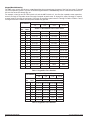
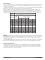
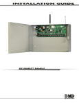
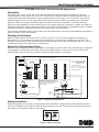
INSTALLATION GUIDE
714 and 715 -8 or -16 Point Zone Expanders
Description
The Model 714-8, 714-16, 715-8, and 715-16 Zone Expanders allow you to increase the number of protection
zones available on a DMP panel. The 714-8 and 714-16 provide an additional eight or sixteen supervised zones for
connecting burglary and non-powered fire alarm initiating devices to the panel. The 715-8 and 715-16 provide an
additional eight or sixteen 12 VDC ungrounded (Class B, Style A) powered zones for connecting two-wire smoke
detectors. Please see the panel installation guide for details on selecting compatible 2-wire smoke detectors.
Each of the zone expanders provide terminal strips for zone inputs and wiring connections, a jumper for LX-Bus™ or
keypad bus designation, and a transmit data LED to indicate panel communication. The expanders mount in a Model
340 enclosure with lock. Separate zone end-of-line resistors and a key are included.
All fire device installations must be in accordance with the manufacturer instructions, NFPA standards, and Authority
Having Jurisdiction (AHJ) requirements.
Mounting the Enclosure
Mount the zone expander metal enclosure in a secure, dry place to protect from damage due to tampering or
the elements. It is not necessary to remove the zone expander circuit board when installing the enclosure. The
enclosure can be surface or flush mounted using the holes provided. Each of the four sides have dual 1/2” and 3/4”
conduit knockouts for running wires out of the enclosure.
Keypad or LX-Bus Jumper Setting
Each of the zone expanders provide a 3-pin header with jumper (J2) used to select the connection type to the panel.
If the expander is connected to the LX-Bus, place the J2 jumper header on the far right two pins. Place the J2
jumper header on the far left two pins when connected to the keypad bus. See Figure 1.
Keypad Bus
Operation
714-8 and 714-16: Use 1k EOL - For listed fire applications use Model 310
715-8 and 715-16: Use 3.3k EOL Model 309
J2 Settings
LX-Bus
Operation
Tens Ones
�
�
RED
J3
�
�
�
To LX-Bus or
Keypad Bus
�
�
TXD
Z1+
Z5+
Z9+
Z13+
Z1–
Z5–
Z9–
Z13–
Z2+
Z6+
Z10+
Z14+
�
�
J2
�
KYPD LX
�
�
�
�
Z2–
Z6–
Z10–
Z14–
RED
Z3+
Z7+
Z11+
Z15+
YEL
Z3–
Z7–
Z11–
Z15–
GRN
Z4+
Z8+
Z12+
Z16+
BLK
Z4–
Z8–
Z12–
J5
J7
J10
3.3k EOL Model 309
714-8 or -16 Ground Fault detection
at 1500 Ohms or less
715-8 or -16 Ground Fault Detection
at 80 Ohms or less
Normal Operating Range:
714-8 or -16
650 - 2100 Ohms
715-8 or -16
1200 - 6000 Ohms
All zones are supervised
Z16–
J12
J14
Maximum line resistance = 100 ohms.
All circuits are supervised and power limited.
See the appropriate Installation Guide for the
number and type of approved 2-wire
Smoke Detectors
2-Wire Smoke Detectors
To panel
smoke detector
power circuit
Power
Supervision
Relay
To zone Positive and Negative
To zone Positive and Negative
3.3k EOL Model 309
Figure 1: Expander Wiring Diagram
Setting the Address
Each zone expander has two rotary switches labeled TENS and ONES to configure the expander address from 00 to
99. To set the address, use a small slotted screwdriver and gently turn the center arrow on the switch clockwise to
the number that matches the address. See Figure 2.
TENS
ONES
0 1
2
3
4
5 6
3
7 8
9
2
7 8
0 1
9
4
5 6
Figure 2: Address Switches
Keypad Bus Addressing
The ONES rotary switch must be set to a starting address that communicates the status of the first four zones (Z1 through
Z4) on the expansion module. The next consecutive keypad address is automatically used to communicate the status of
the next four zones (Z5 through Z8), etc.
For example, when you set the TENS switch to 0 and the ONES switch to 2, the first four expander zones respond as
zones 21 through 24. Expander zones 5 through 8 respond as panel zones 31 through 34; zones 9 through 12 respond
as panel zones 41 through 44; and zones 13 through 16 respond as panel zones 51 through 54. Refer to Tables 1 and 2
for keypad bus zone numbers and the panels where they operate.
Expander Zones
Start Address
1-4
Switches
TensOnes
5-8
9-12
13-16
XR500 or XR350/XR550 Series Panel Zones
0
1
11 to 14
21 to 24
31 to 34
41 to 44
0
2
21 to 24
31 to 34
41 to 44
51 to 54
0
3
31 to 34
41 to 44
51 to 54
61 to 64
0
4
41 to 44
51 to 54
61 to 64
71 to 74
0
5
51 to 54
61 to 64
71 to 74
81 to 84
0
6
61 to 64
71 to 74
81 to 84
91 to 94
0
7
71 to 74
81 to 84
91 to 94
101 to 104
0
8
81 to 84
91 to 94
101 to 104
111 to 114
0
9
91 to 94
101 to 104
111 to 114
121 to 124
1
0
101 to 104
111 to 114
121 to 124
131 to 134
1
1
111 to 114
121 to 124
131 to 134
141 to 144
1
2
121 to 124
131 to 134
141 to 144
151 to 154
1
3
131 to 134
141 to 144
151 to 154
161 to 164
1
4
141 to 144
151 to 154
161 to 164
None
1
5
151 to 154
161 to 164
None
None
1
6
161 to 164
None
None
None
Table 1: Keypad Bus Zone Numbers
Start Address
Switches
TensOnes
Expander Zones
1-4
5-8
9-12
13-16
Panel Zones
XT30, XT50, XR100 or XR150
0
1
11 to 14
21 to 24
31 to 34
41 to 44
0
2
21 to 24
31 to 34
41 to 44
51 to 54
0
3
31 to 34
41 to 44
51 to 54
61 to 64
0
4
41 to 44
51 to 54
61 to 64
71 to 74
0
5
51 to 54
61 to 64
71 to 74
81 to 84
0
6
61 to 64
71 to 74
81 to 84
None
0
7
71 to 74
81 to 84
None
None
0
8
81 to 84
None
None
None
Table 2: Keypad Bus Zone Numbers
Digital Monitoring Products
2
714-715 Installation Guide
LX-Bus Addressing
When connecting to the LX-Bus, the rotary switch settings on the expanders must match the second two digits of the
first panel zone being used. The next 15 zone addresses are automatically used to communicate the status of the
expander zones 2 through 16.
For example, if you set the TENS switch to 3 and the ONES switch to 2, the sixteen zones on the expander respond as
panel zones 532 to 547. When connected to LX-Bus 2, the zones respond as 632 to 647.
Note: The LX-Bus provides zones 500 through 599, 600 through 699, 700 through 799, 800 through 899 and 900
through 999 on XR500 Series or XR350/XR550 Series panels. On XR100 and XR150 panels the LX-Bus provides zones
500 through 599. When addressing the module, use an address that provides the proper number of zones. For
example, if you set the switch address on the module to 99, you can only use one zone as shown in Table 3 below.
Start
Address
Switch
TensOnes
Panel LX-Bus Numbers and their corresponding Zone Numbers
XR500 and XR550 Series
XR100
and
XR150
Series
(LX500 - LX900)
XR350 Series (LX500 - LX700)
1(LX500)
1(LX500)
2(LX600)
3(LX700)
4(LX800)
5(LX900)
0
0
500
500
600
700
800
900
0
1
501
501
601
701
801
901
0
2
502
502
602
702
802
902
0
3
503
503
603
703
803
903
0
4
504
504
604
704
804
904
...
...
...
...
...
...
...
...
9
5
595
595
695
795
895
995
9
6
596
596
696
796
896
996
9
7
597
597
697
797
897
997
9
8
598
598
698
798
898
998
9
9
599
599
699
799
899
999
Table 3: LX-Bus Zone Numbers
Wiring
Each zone expander can connect to a panel keypad bus. Also, the zone expander can connect to an XR100/XR500 or
XR150/XR350/XR550 Series panel LX-Bus. On an XR100/XR500 Series, the zone expander can connect directly to the
LX-Bus Connector (J22) on the panel or use an LX-Bus Interface card such as a 481 or 463C, as shown in Figure 1. All
circuits are power limited.
On an XR150/XR350/XR550 Series: connect the zone expander directly to the LX500 - LX900 connectors on the panel.
Note: 481, 463C, 462P, and 462N LX-Bus Interface Cards are not for use with XR150/XR350/XR550 Series panels.
Wiring the 715-8/16 Module
For the 715-8/16 module, connect the Red wire to the panel Smoke power terminal. This allows Sensor Reset
to drop power to the module and devices connected to its zones. Alternately, connect Red to a regulated, power
limited power supply listed for Fire Protective Signaling through a Model 716 relay. Use the Sensor Reset Output
programming to drop power to the 715-8/16 Module.
714-715 Installation Guide
Digital Monitoring Products
3
Wiring Specifications for Keypad and LX-Bus
1. DMP recommends using 18 or 22-gauge unshielded wire for all keypad and LX-Bus circuits. Do Not use twisted
pair or shielded wire for LX-Bus and keypad bus data circuits. To maintain auxiliary power integrity when
using 22-gauge wire do not exceed 500 feet. When using 18-gauge wire do not exceed 1,000 feet. Install an
additional power supply to increase the wire length or add devices.
2. Maximum distance for any one circuit (length of wire) is 2,500 feet regardless of the wire gauge. This distance
can be in the form of one long wire run or multiple branches with all wiring totaling no more than 2,500 feet.
As wire distance from the panel increases, DC voltage on the wire decreases.
3. Maximum number of devices per 2,500 feet circuit is 40.
Note: Each panel allows a specific number of supervised keypads. Add additional keypads in the unsupervised
mode. Refer to the panel installation guide for the specific number of supervised keypads allowed.
4. Maximum voltage drop between the panel (or auxiliary power supply) and any device is 2.0 VDC. If the voltage
at any device is less than the required level, add an auxiliary power supply at the end of the circuit. When
voltage is too low, the devices cannot operate properly.
For additional information refer to the panel installation guide and LX-Bus/Keypad Bus Wiring Application Note
(LT-2031) or the 710 Installation Guide (LT-0310).
Compliance Listing Specifications
UL
To comply with ANSI/UL 365 Police-Connected Burglary System or ANSI/UL 609 Local Burglary Alarm Systems, the
module must be mounted in the supplied, UL listed enclosure with a tamper.
Any power supply used in a fire listed installation must be regulated, power limited, and listed for Fire Protective Signaling.
ULC Commercial Burglary (XR100/XR500 Series or XR150/XR350/XR550 Series Panels)
A DMP Model 307 Clip-on Tamper Switch programmed as a 24-Hour zone is required on the zone expander enclosure.
The 714/715 zones can be installed in Medium or High Risk applications when two zones are used as shown in the Dual
Zone Protection diagram in the XR100/XR500 or XR150/XR350/XR550 Canadian Installation guides. Otherwise, 714/715
zones can only be used in Low Risk Applications.
ULC Residential Fire
Refer to the table below for ULC approved 2-Wire Smoke Detectors. Refer to the panel installation guide for the
complete list of UL approved smoke detectors.
Manufacturer
Model
Detector ID
DC Voltage Range
# of Detectors
Sentrol/ESL
528B, 528BXT
S09A
6.5-20
12
Enclosure Specifications
Enclosure
Dimensions
714-8/-16 Color
715-8/-16 Color
20-Gauge cold-rolled steel
12.5” W x 11.5” H x 3.5” D
Gray
Red
Compatibility
Listings and Approvals
California State Fire Marshal (CSFM)
New York City (FDNY COA #6123)
New York City 1100 Series Wireless (FDNY COA #6145)
Underwriters Laboratories (UL) Listed
ANSI/UL 365 Police Station Connect Burglar Alarm Systems
ANSI/UL 609 Local Burglar Alarm Units & Systems
ANSI/UL 864 Fire Protective Signaling Systems
ANSI/UL 985 Household Fire Warning System Units
ANSI/UL 1023 Household Burglar Alarm System Units
ANSI/UL 1076 Proprietary Burglar Alarm Units & Systems
ANSI/UL 1610 Central Station Burglar Alarm Units
ANSI/UL 1635 Digital Alarm Communication System Units
Underwriters Laboratories Canada (ULC) Listed
ULC Subject-C1023 Household Burglar
ULC/ORD-C1076 Proprietary Burglar
ULC S304 Central Station Burglar
ULC S545
Household Fire
XT30/XT50 Series panels
XR100/XR500 Series panels
XR150/XR350/XR550 Series panels
800 - 641 - 4282
INTRUSION
•
FIRE
•
ACCESS
•
NETWORKS
www.dmp.com
2500 North Partnership Boulevard
Designed, Engineered
and Assembled in U.S.A.
S p r i n g fi e l d , M i s s o u r i 6 5 8 0 3 - 8 8 7 7
14035
Operating Voltage 8.8 to 15.0 VDC
Operating Current
714-8/16
Average
20mA + 1.6mA per zone
Alarm
20mA + 2mA per zone
715-8/16
Average
20mA + 4mA per zone
+ 0.1 per 2-wire smoke
Alarm
20mA
+ 58mA per shorted zone
+ 0.1 per 2-wire smoke
+ 30mA per smoke in alarm
LT-0401 1.06 © 2014 Digital Monitoring Products, Inc.
Specifications