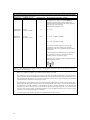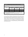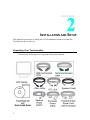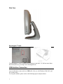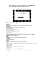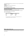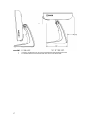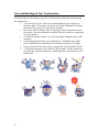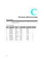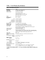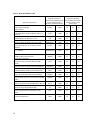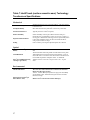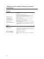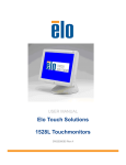
1
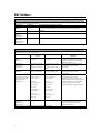
Touchmonitor User Guide 1528L 15-inch LCD Desktop Touchmonitor Model ET1528L User Guide 15-inch LCD Desktop 1528L Touchmonitor Revision B P/N E894354 ii Copyright 2008 Tyco Electronics Corporation. All Rights Reserved. No part of this publication may be reproduced, transmitted, transcribed, stored in a retrieval system, or translated into any language or computer language, in any form or by any means, including, but not limited to, electronic, magnetic, optical, chemical, manual, or otherwise without prior written permission of Tyco Electronics Corporation. Disclaimer The information in this document is subject to change without notice. Tyco Electronics Corporation makes no representations or warranties with respect to the contents hereof, and specifically disclaims any implied warranties of merchantability or fitness for a particular purpose. Tyco Electronics reserves the right to revise this publication and to make changes from time to time in the content hereof without obligation of Tyco Electronics to notify any person of such revisions or changes. Trademark Acknowledgments AccuTouch, CarrollTouch, Elo TouchSystems, IntelliTouch, SecureTouch, TouchTools, Tyco Electronics and the TE logo are trademarks. Other product names mentioned herein may be trademarks or registered trademarks of their respective companies. iii Warnings and Cautions Warning • Danger — Explosion hazard. Do not use in the presence of flammable anesthetics. • To prevent fire or shock hazards, do not immerse the unit in water or expose it to rain or moisture. • Do not use the unit with an extension cord receptacle or other outlets unless the prongs of the power cord can be fully inserted. • RISK OF ELECTRICAL SHOCK — DO NOT OPEN. To reduce the risk of electrical shock, DO NOT remove the back of the equipment or open the enclosure. No user-serviceable parts are inside. Refer servicing to qualified field service engineers only. • Uninsulated voltage within the unit may have sufficient magnitude to cause electrical shock. Avoid contact with any part inside the unit. Caution • Before connecting the cables to your Elo TouchSystems touchmonitor, make sure all components are powered OFF. • The use of ACCESSORY equipment not complying with the equivalent safety requirements of this equipment may lead to a reduced safety of the resulting system. Consideration relating to the choices of accessory equipment should include: Use of accessory in the patient vicinity. Evidence that the safety certification of the accessory has been performed in accordance to the appropriate IEC 60601-1 and/or IEC 60601-1-1 harmonized national standard. • For continued safety — - This unit only complies to the above standards if used with a medical grade power cord. - A medical grade power adaptor, such as the one specified, is required for use in a medical application. Note: • This symbol alerts the user to important information concerning the operation and maintenance of this unit, which should be read carefully to avoid problems. CAUTION-Life Support Care must be taken when this touchmonitor is a critical component of a Life support system or device. In case of failure of this touchmonitor, appropriate redundant systems should be incorporated into the system or device to prevent injury to the user or patient. The following should be an integral part of the safety design of a Life support system or device using this touchmonitor for a critical function. ♦ An Alternate interface or fail-safe must be available should the touchscreen fail to operate. ♦ The touchscreen interface must not be the only means of control of a critical function. ♦ An Alternate video monitor should be incorporated into the safety design if used to monitor a critical function. ♦ The internal speakers of this touchmonitor must not be the sole method of warning of a critical function. Critical functions are: 1. Life support devices or systems are devices or systems which, (a) are intended for surgical implant into the body, or (b) support or sustain life, or (c) whose failure to perform when properly used in accordance with instructions for use provided in the labeling, can be reasonably expected to result in significant injury to the user. 2. A critical component is any component of a life support device or system whose failure to perform can be reasonably expected to cause the failure of the life support device or system, or to affect its safety or effectiveness. iv EMC Guidance Guidance and manufacturer’s declaration – electromagnetic emissions The 1528L is intended for use in the electromagnetic environment specified below. The customer or the user of the 1528L should assure that it is used in such an environment. Emissions test Compliance Electromagnetic environment – guidance RF emissions Group 1 The 1528L uses RF energy only for its internal function. Therefore, its RF emissions CISPR 11 are very low and are not likely to cause any interference in nearby electronic equipment. RF emissions Class B Harmonic Not applicable emissions IEC61000-3-2 Voltage Complies fluctuations/ flicker emissions IEC61000-3-3 Guidance and manufacturer’s declaration – electromagnetic immunity The 1528L is intended for use in the electromagnetic environment specified below. The customer or the user of the 1528L should assure that it is used in such an environment. IEC60601 Electromagnetic environment – Immunity test Compliance level test level guidance Electrostatic discharge ±6 kV Contact ±6 kV Contact Floors should be wood, concrete or (ESD) ±8 kV air ±8 kV air ceramic tile. If floors are covered with IEC61000-4-2 synthetic material the relative humidity should be at least 30 % Electrical fast ±2 kV for power supply ±2 kV for power supply Main power quality should be that of a transient/burst lines lines typical commercial or hospital IEC61000-4-4 ±1 kV for input/output ±1 kV for input/output environment. lines lines Surge ±1 kV differential mode ±1 kV differential mode Main power quality should be that of a IEC6100-4-5 ±2 kV common mode ±2 kV common mode typical commercial or hospital environment. Voltage dips, short <5 % UT Main power quality should be that of a <5 % UT interruptions and voltage (>95 % dip in UT) (>95 % dip in UT) typical commercial or hospital for 0,5 cycle for 0,5 cycle variations on the power environment. If the user of the 1528L supply input lines requires continued operation during power 40 % UT 40 % UT IEC61000-4-11 mains interruptions, it is recommended (60 % dip in UT) (60 % dip in UT) that the 1528L be powered from an for 5 cycles for 5 cycles uninterruptible power supply or a battery. 70 % UT (30 % dip in UT) for 25 cycles 70 % UT (30 % dip in UT) for 25 cycles <5 % UT (>95 % dip in UT) for 5 sec <5 % UT (>95 % dip in UT) for 5 sec Power frequency 3 A/m 3 A/m, 30 A/m (50/60 Hz) Magnetic field IEC61000-4-8 NOTE UT is the ac. mains voltage prior to application of the test level. v Power frequency magnetic fields should be at levels characteristic of a typical location in a typical commercial or hospital environment. Guidance and manufacture’s declaration – electromagnetic immunity The 1528L is intended for use in the electromagnetic environment specified below. The customer or the user of the 1528L should assure that it is used in such an environment. Immunity Test IEC60601 test level Compliance level Electromagnetic environment – guidance Portable and mobile RF communications equipment should be used no closer to any part of the [EQUIPMENT or SYSTEM], including cables, than the recommended separation distance calculated from the equation applicable to the frequency of the transmitter. Recommended separation distance __ Conducted RF 3 Vrms 3V d = 1,2 √P IEC61000-4-6 150 kHz to 80 MHz Radiated RF IEC61000-4-3 10 Vrms 80 MHz to 2.5 GHz 3 V/m __ d = 1,2 √P 80 MHz to 800 MHz __ d = 2,3 √P 800 MHz to 2,5 GHz where P is the maximum output power rating of the transmitter in watts (W) according to the transmitter manufacturer and d is the recommended separation distance in meters (m).b Field strengths from fixed RF transmitters, as determined by an electromagnetic site survey,c should be less than the compliance level in each frequency range.d Interference may occur in the vicinity of equipment marked with the following symbol: NOTE 1 At 80 MHz and 800 MHz, the higher frequency range applies. NOTE 2 These guidelines may not apply in all situations. Electromagnetic propagation is affected by absorption and reflection from structures, objects and people. a The ISM (industrial, scientific, and medical) bands between 150 kHz and 80 MHz are 6,765 MHz to 6,795 MHz; 13,553 MHz to 13,567 MHz; 26,957 MHz to 27,283 MHz; and 40,66 MHz to 40,70 MHz. b The compliance levels in the ISM frequency bands between 150 kHz and 80 MHz and the frequency range 80 MHz to 2,5 GHz are intended to decrease the likelihood that mobile/portable communications equipment could cause interference if it is inadvertently brought into patient areas. For this reason, an additional factor of 10/3 is used in calculating the recommended separation distance for transmitters in these frequency ranges. c Field strengths from fixed transmitters, such as base stations for radio (cellular/cordless) telephones and land mobile radios, amateur radio, AM and FM radio broadcast cannot be predicted theoretically with accuracy. To assess the electromagnetic environment due to fixed RF transmitters, an electromagnetic site survey should be considered. If the measured field strength in the location in which the 1528L is used exceeds the applicable RF compliance level above, the 1528L should be observed to verify normal operation. If abnormal performance is observed, additional measures may be necessary, such as reorienting or relocating the [EQUIPMENT or SYSTEM]. d Over the frequency range 150 kHz to 80 MHz, field strengths should be less than [V1] V/m. vi Recommended separation distances between Portable and mobile RF communications equipment and the 1528L The 1528L is intended for use in which radiated RF disturbances are controlled. The customer or the user of the 1528L can help prevent electromagnetic interference by maintaining a minimum distance between portable and mobile RF communications equipment (transmitters) and the 1528L as recommended below, according to the maximum output power of the communications equipment. Separation distance according to frequency of transmitter M Rated maximum output power 80 MHz to 800 MHz 800 MHz to 2,5 GHz 150 kHz to 80 MHz of transmitter __ __ __ W d = 1,2 √P d = 2,3 √P d = 1,2 √P 0,01 0,12 0,12 0,23 0.1 0,38 0,38 0.73 1 1,2 1,2 2,3 10 3,8 3,8 7,3 100 12 12 23 For transmitters rated at a maximum output power not listed above, the recommended separation distance d in meters (m) can be estimated using the equation applicable to frequency of the transmitter, where P is the maximum output power rating of the transmitter in watts (W) according to the transmitter manufacturer. NOTE 1 At 80 MHz and 800 MHz, the separation distance for the higher frequency range applies. NOTE 2 These guidelines may not apply in all situations. Electromagnetic propagation is affected by absorption and reflection from structures, objects and people. This device complies with all applicable electromagnetic emission and immunity standards for medical device equipment. This device is designed to not cause harmful interference, and to accept any interference received, including interference that may cause undesired operation. The performance of this device is limited to the emission and immunity standards that have been applied. Other devices which are not designed to withstand emission levels as specified in the medical device standards may be susceptible to interference from this device. Subjecting the device to conditions beyond the rated performance capabilities may result in emissions in excess of the standard. If it is determined that this device produces electromagnetic or other interference it must be disconnected from power until the cause of the problem has been determined and resolved. If it is determined that this device is functioning improperly due to electromagnetic and other interference it must be disconnected from power until the cause of the problem has been determined and resolved. vii Classification With respect to electrical shock, fire in accordance with UL60601-1 and CAN/CSA C22.2 No. 60601-1 This monitor is a CLASS 1 (GROUNDED) DEVICE. This monitor is classified NO APPLIED PARTS EQUIPMENT. Protection against harmful ingress of water: INGRESS PROTECTION (IPX1) This monitor shall be classified as ORDINARY EQUIPMENT, not intended or evaluated for use in the presence of flammable anesthetic mixture with air, oxygen, or nitrous oxide. Mode of Operation: CONTINUOUS OPERATION. Environmental conditions for transport and storage Temp. Operating 0°C to 40°C Storage -20°C to +60°C Humidity (non-condensing) Operating Storage Altitude Operating Storage 20% to 80% 5% to 90% 0 to + 12,000 feet [3,658m]. Equiv. to 14.7 to 10.1 psia. 0 to + 40,000 feet [12,192m]. Equiv. to 14.7 to 4.4 psia. For full Product Specifications refer to Appendix C viii Table of Contents Warnings and Cautions.................................................................................. iv EMC Guidance................................................................................................................ v Classification................................................................................................................ viii INTRODUCTION .......................................................................................... 3 Product Description ........................................................................................................ 3 LCD Monitor Performance Features .............................................................................. 3 15 inch TFT LCD Monitor Panel................................................................................ 3 External Medical Grade Power Adaptor..................................................................... 4 INSTALLATION AND SETUP .................................................................... 5 Unpacking Your Touchmonitor...................................................................................... 5 Product Overview ........................................................................................................... 6 Front View .................................................................................................................. 6 Rear View ................................................................................................................... 6 Side View.................................................................................................................... 7 KensingtonTM Lock................................................................................................... 7 USB Interface Connection .............................................................................................. 7 Replace the Cable Cover............................................................................................... 10 Optimizing the LCD Monitor ....................................................................................... 10 Installing the Touch Driver Software ........................................................................... 10 Installing the USB Touch Driver .................................................................................. 11 Installing the USB Touch Driver for Windows XP, Windows 2000, Me and 98..... 11 OPERATION................................................................................................ 13 About Touchmonitor Adjustments ............................................................................... 13 Controls and Adjustment .............................................................................................. 14 OSD Lock/Unlock .................................................................................................... 14 Power Lock/Unlock .................................................................................................. 14 OSD Menu Functions ............................................................................................... 14 OSD Control Options (Clockwise) ........................................................................... 15 Power LED Monitor & Power Saving .......................................................................... 16 General Power Saving Mode .................................................................................... 16 Monitor Angle (desktop only) ...................................................................................... 16 TROUBLESHOOTING................................................................................ 18 Solutions to Common Problems ................................................................................... 18 NATIVE RESOLUTION ............................................................................. 19 TOUCHMONITOR SAFETY...................................................................... 20 Care and Handling of Your Touchmonitor................................................................... 21 TECHNICAL SPECIFICATIONS............................................................... 22 Monitor Modes.............................................................................................................. 22 Item ........................................................................................................................... 22 Resolution ................................................................................................................. 22 1 Type .......................................................................................................................... 22 H. Scan (KHz)........................................................................................................... 22 V. Scan (Hz).............................................................................................................. 22 Polarity...................................................................................................................... 22 1528L - Touchmonitor Specifications ......................................................................... 23 Power Adaptor Cord Selection ..................................................................................... 24 North America .......................................................................................................... 24 Cord selection for other than North America ........................................................... 25 Argentina IRAM Ireland NSAI ............................................................................ 25 IntelliTouch (surface acoustic wave) Touchscreen Specifications............................... 27 AccuTouch (resistive) Touchscreen Specifications...................................................... 28 CarrollTouch (infrared) Touchscreen Specifications.................................................... 29 CONTACT ELO........................................................................................... 30 Contact Elo.................................................................................................................... 30 Replacement Parts......................................................................................................... 30 REGULATORY INFORMATION .............................................................. 31 WARRANTY ............................................................................................... 34 2 CHAPTER INTRODUCTION Product Description The 1528L is a medical 15-inch touchmonitor which uses liquid crystal monitor (LCD) technology, designed to present information to the operator, care-giver and the patient. The 1528L features both serial and USB touch interfaces as standard configuration. The 1528L functionally consists of a 15-inch LCD main monitor with a touchscreen. The monitor element is a 15.0 inch diagonal XGA resolution (1024x768) LCD monitor. Three types of touchscreen technology are offered for the 1528L as standard options: AccuTouch technology (resistive), IntelliTouch technology, Surface Acoustic Wave (SAW), and CarrollTouch technology (Infrared /IR/). The 1528L is powered by 12 VDC from an external medical grade power adapter. LCD Monitor Performance Features 15 inch TFT LCD Monitor Panel Monitor format Monitor area Pixel pitch Contrast ratio Brightness LCD AccuTouch technology IntelliTouch technology CarrollTouch technology AccuTouch transmission IntelliTouch transmission IR Touchscreen transmission Response time Monitor color Typical vertical viewing angle: Typical horizontal viewing angle: 3 1024x768 304.1 mm (H) x 228 mm (V) 0.297 mm (H) x 0.297 mm (V) 400:1 typical 350 cd/m² (Typical) 287 cd/m² (Typical) 322 cd/m² (Typical) 322 cd/m² (Typical) 82% typical 92% typical 92% typical Tr = 12 msec / Tf = 16 msec typical 16.2 million colors, 6 Bit with dithering 60 deg (looking down) / 40 deg (looking up) 60 deg (looking left) / 60 deg (looking right) External Medical Grade Power Adapter The 1528L is powered by an external medical grade universal input power adapter. Power adapter: 4 AC power: Input voltage 100 - 240 Vac Input frequency 50 / 60 Hz DC output: 12 Vdc Line and load regulation: ± 3 % CHAPTER INSTALLATION AND SETUP This chapter discusses how to install your LCD touchmonitor and how to install Elo TouchSystems driver software. Unpacking Your Touchmonitor Check that the following items are present and in good condition: 5 Product Overview Front View Rear View 6 Side View Kensington™ Lock The Kensington™ lock is a security device that prevents theft. To find out more about this security device, go to http://www.kensington.com. USB Interface Connection Your touchmonitor comes with one USB cable. (For use with Windows 2000, ME, and XP systems only.) To set up the monitor, please refer to the following figures and procedures: 7 Remove the Cable Cover The cables are connected at the back of the monitor. CAUTION Before connecting the cables to your touchmonitor and PC, be sure that the computer and touchmonitor are turned off. To remove the cable cover, place your thumbs at the top corners of the cable cover where the indents are (above the arrows). Gently press and pull the cover toward yourself. NOTE Before connecting the cables to the touchmonitor, route all the cables that you will be using through the hole in the base as shown in the picture above. Only use one of the following: Serial or USB touch cable and D-Sub 15 video cable or DVI video cable. The following illustrations guide you step by step in connecting your touchmonitor using a Serial or USB cable connection with D-Sub 15 or DVI video cable.. or 8 Connect one end of the video cable to the rear side of computer and the other to the LCD. Tighten by turning the two thumb screws clockwise to ensure proper grounding. You can select D-SUB15 video cable or DVI video cable, shown respectively. Connect one end of the speaker cable to the speaker port in the computer and the other end to the port in the monitor. or Connect one end of the Serial or USB cable to the rear side of the computer and the other to the LCD monitor, shown respectively. Connect the cylindrical connecter from the power adaptor to the monitor. Connect the appropriate power cord to the power adaptor and to the appropriate power outlet. 9 Replace the Cable Cover After you have attached all the cables to the monitor; gently bring all the cables toward the center so they fit under the cable cover lip. Snap the cable cover in place over the connections. Optimizing the LCD Monitor To ensure the LCD monitor works well with your computer, configure the monitor mode of your graphic card to make it less than or equal to 1024 x 768 resolution, and make sure the timing of the monitor mode is compatible with the LCD monitor. Refer to Appendix A for more information about resolution. Compatible video modes for your touchmonitor are listed in Appendix C. Installing the Touch Driver Software Driver software that allows your touchmonitor to work with your computer comes with the Elo TouchSystems monitor. Drivers are located on the enclosed TouchTools CD-ROM for the following operating systems: • Windows XP • Windows 2000 • Windows Me • Windows 98 • Windows 95 • Windows NT 4.0 • CE 2.x, 3.0, 4x • Windows XP Embedded • Windows 3.x •MS DOS •OS/2 10 Additional drivers and driver information for other operating systems (including Macintosh and Linux) are available on the Elo TouchSystems web site at www.elotouch.com. Your Elo USB touchmonitor is “plug-and-play” compliant. Information on the video capabilities of your touchmonitor is sent to your video monitor adapter when Windows starts. If Windows detects your touchmonitor, follow the instructions on the screen to install a generic plug-and-play monitor. Refer to the appropriate section below for driver installation instructions. Installing the USB Touch Driver Installing the USB Touch Driver for Windows XP, Windows 2000, Windows Me and Windows 98 Insert the TouchTools CD-ROM in your computer’s CD-ROM drive. If Windows XP, Windows 2000, Windows 98, or Windows Me starts the Add New Hardware Wizard, then: 1. Choose Next. Select “Search for the best driver for your device (Recommended)” and choose Next. 2. When a list of search locations is monitored, place a checkmark on “Specify a location” and use Browse to select the \EloUSB directory on the TouchTools CD-ROM. 3. Choose Next. Once the Elo TouchSystems USB touchscreen driver has been detected, choose Next again. 4. You will see several files being copied. Insert your Windows 98 CD if prompted. Choose Finish. If Windows XP, Windows 2000, Windows 98, or Windows Me does not start the Add New Hardware Wizard: NOTE: For Windows XP and Windows 2000, you must have administrator access rights to install the driver. 1. If the AutoStart feature for your CD-ROM drive is active, the system automatically detects the CD and starts the setup program. 2. Follow the directions on the screen to complete the driver setup for your version of Windows. If the AutoStart feature is not active: 1. Click Start > Run. 2. Click the Browse button to locate the EloCd.exe program on the CDROM. 3. Click Open, then OK to run EloCd.exe. 11 4. Follow the directions on the screen to complete the driver setup for your version of Windows. 12 CHAPTER OPERATION About Touchmonitor Adjustments Your touchmonitor will unlikely require adjustment. Variations in video output and application may require adjustments to your touchmonitor to optimize the quality of the display. For best performance, your touchmonitor should be operating in native resolution, that is 1024x768 at 60-75 Hz. Use the Display control panel in Windows to choose 1024x768 resolution. Operating in other resolutions will degrade video performance. For further information, please refer to Appendix A. All adjustments you make to the controls are automatically memorized. This feature saves you from having to reset the choices every time the power is unplugged or the touchmonitor is turned off and on. If there is a power failure, your touchmonitor settings will not default to the factory specifications. To restore factory set up, choose it from the OSD. See page 3-25. 13 Table 1 - User controls # 1 2 3 Control MENU ▲ ▼ Function Menu monitor and menu exit. Adjusts the increasing value of the selected OSD control option. Adjusts the decreasing value of the selected OSD control option. (HotButton for Audio Volume) 4 SELECT Monitors the OSD menus on the screen and used to select (“Clockwise” and “Counter-clockwise” direction) the OSD control options on the screen. (Hot-Button for Auto-Adjust) 5 POWER Turns the monitor system power on or off. Controls and Adjustment OSD Menu Functions To monitor the OSD Menu, press the MENU button. 1 Press the ▲ button or the ▼ button to select the different OSD control option. 2 When the function you want to change is monitored, press the Select button. To adjust the Value of the function: 1 Press the ▲ button to increase the value of the selected OSD control option. 2 Press the ▼ button to decrease the value of the selected OSD control option. After adjusting the values, the monitor will automatically save the changes. NOTE: The OSD screen will disappear if no input activities are detected for 45 seconds. OSD Lock/Unlock You are able to lock and unlock the OSD feature. The monitor is shipped in the unlocked position. To lock the OSD: Press the MENU button and the ▲button simultaneously for 2 seconds. A window will appear monitoring OSD UNLOCK. Continue to hold the buttons down for another 2 seconds and the window toggles to OSD LOCK. Repeat this procedure to unlock (toggle) the OSD feature. Power Lock/Unlock You are able to lock/unlock the Power feature. The monitor is shipped in the unlocked position. To lock the power: Press the MENU button and the ▼ button simultaneously for 2 seconds. A window will appear monitoring POWER UNLOCK. Continue to hold the 14 buttons for another 2 seconds and the window toggles to POWER LOCK. Repeat this procedure to unlock (toggle) the Power button. Figure 1 - OSD Main Menu OSD Control Options (Clockwise) Contrast • Adjusts the contrast or the values of color gain (RED, GREEN or BLUE). Brightness • Background luminance of the LCD panel is adjusted. Vertical Position • Adjusts vertical position of image. Horizontal Position • Adjusts horizontal position of image. Recall Defaults • Recalls the factory OSD default settings. RGB - Color Temperature • Select preset color temperature of 9300°K, 6500°K, 5500°K, 7500°K or select USER to customize Red, Green and Blue gain. Audio • Adjust audio volume of speakers internal to the 1528L monitor. Sharpness • Adjust image sharpness. Phase • Adjusts the phase of the dot clock. Adjust for best image. Clock • Adjusts the ratio of dividing frequency of the dot clock. Adjust to remove vertical dark bands in image. OSD Left/Right • The OSD screen is moved vertically right and left. OSD Up/Down • The OSD screen is moved vertically up and down. OSD Timeout • Adjusts the amount of time in which the OSD will disappear (45 to 255 seconds). Auto Adjust 15 • Horizontal and vertical frequencies are monitored. Press select to automatically adjust image (under 5 seconds). Language • Selects the languages used for OSD menu monitor. Input Select • Use to select analog or digital input. Power LED Monitor & Power Saving General Power Saving Mode When the power is on and video is present, this LED lights in green. The LED indicates the different power status with altered LED colors when monitor operates in different modes (see following table). Table 2 - Power Saving Indicator Mode Power Consumption Indicator On Sleep Off 30 w max. 6 w max. 5w Green Orange NO Note: If the monitor is not to be used for an extended period of time, it is recommended that the monitor be turned off. Monitor Angle (desktop only) For viewing clarity, you can tilt the LCD forward or back for the best viewing angle and minimum glare. 16 CAUTION 17 In order to protect the LCD, be sure to hold the base when adjusting the LCD. For models without a touchscreen take care not to touch the screen. CHAPTER TROUBLESHOOTING If you are experiencing trouble with your touchmonitor, refer to the following table. If the problem persists, please contact your local dealer or our service center. Elo Technical Support numbers are listed on page 28. Solutions to Common Problems Problem Suggestion(s) The monitor does not respond • • Characters on the screen are dim • The screen is blank • • OSD or power buttons don’t work • “Out of Range” monitor • • Touch doesn’t work 18 • Check that the monitor’s Power Switch is on. Turn off the power and check the monitor’s power cord and signal cable for proper connection. Refer to the Controls and Adjustments section to adjust the brightness. During operation, the monitor screen may automatically turn off as a result of the Power Saving feature. Press any key to see if the screen reappears. Refer to the Controls and Adjustments section to adjust the brightness. Check to see that they are not locked out. See page 13. Check to see of the resolution or vertical frequency of your computer is higher than that of the LCD monitor. Reconfigure the resolution of your computer to make it less than or equal to 1024x768. 1024x768 is optimal. See Appendix A for more information on resolution. Make sure cable is securely attached at both ends. APPENDIX NATIVE RESOLUTION The native resolution of a monitor is the resolution level at which the LCD panel is designed to perform best. For the Elo TouchSystems LCD touchmonitor, the native resolution is 1024 x 768 for the 15.0 inch size. In almost all cases, screen images look best when viewed at their native resolution. You can lower the resolution setting of a monitor but not increase it. Input Video 15.0" LCD 640x480 (VGA) 800x600 (SVGA) 1024x768(XGA) Transforms input format to 1024x768 Transforms input format to 1024x768 Monitor in Native Resolution The native resolution of an LCD is the actual number of pixels horizontally in the LCD by the number of pixels vertically in the LCD. LCD resolution is usually represented by the following symbols: VGA SVGA XGA 640x480 800x600 1024x768 As an example, a SVGA resolution LCD panel has 800 pixels horizontally by 600 pixels vertically. Input video is also represented by the same terms. XGA input video has a format of 1024 pixels horizontally by 768 pixels vertically. When the input pixels contained in the video input format match the native resolution of the panel, there is a one to one correspondence of mapping of input video pixels to LCD pixels. As an example, the pixel in column 45 and row 26 of the input video is in column 45 and row 26 of the LCD. For the case when the input video is at a lower or higher resolution than the native resolution of the LCD, the direct correspondence between the video pixels and the LCD pixels is lost. The LCD controller can compute the correspondence between video pixels and LCD pixels using algorithms contained on its controller. The accuracy of the algorithms determines the fidelity of conversion of video pixels to LCD pixels. Poor fidelity conversion can result in artifacts in the LCD displayed image such as varying width characters. 19 APPENDIX TOUCHMONITOR SAFETY This manual contains information that is important for the proper setup and maintenance of your touchmonitor. Before setting up and powering on your new touchmonitor, read through this manual, especially Chapter 2 (Installation), and Chapter 3 (Operation). 1. To reduce the risk of electric shock, follow all safety notices and never open the touchmonitor case. 2. Turn off the product before cleaning. (See page 19 for Cleaning Instructions.) 3. Your touchmonitor is equipped with a 3-wire, grounding power cord. The power cord plug will only fit into a grounded outlet. Do not attempt to fit the plug into an outlet that has not been configured for this purpose. Do not use a damaged power cord. Use only the power cord that comes with your Elo TouchSystems touchmonitor. Use of an unauthorized power cord may invalidate your warranty. 4. The slots located on the sides and top of the touchmonitor case are for ventilation. Do not block or insert anything inside the ventilation slots. 5. It is important that your touchmonitor remains dry. Do not pour liquid into or onto your touchmonitor. If your touchmonitor becomes wet do not attempt to repair it yourself. 20 Care and Handling of Your Touchmonitor The following tips will help keep your Elo TouchSystems touchmonitor functioning at the optimal level. To avoid risk of electric shock, do not disassemble the power adaptor or monitor cabinet. The monitor is not user serviceable. Remember to unplug the monitor from the power outlet before cleaning. Do not use alcohol (methyl, ethyl or isopropyl) or any strong dissolvent on the monitor. Do not use thinner or benzene, abrasive cleaners or compressed air on the monitor. To clean the monitor cabinet, use a soft cloth lightly dampened with a mild detergent. Avoid getting liquids inside your touchmonitor. If liquid does get inside, have a qualified service technician check it before you power it on again. Do not wipe the screen with a cloth or sponge that could scratch the surface. To clean the touchscreen, use window or glass cleaner. Put the cleaner on a soft cloth and wipe the touchscreen. Never apply the cleaner directly on the touchscreen. 21 APPENDIX TECHNICAL SPECIFICATIONS Display Modes Your Elo TouchSystems touchmonitor is compatible with the following standard video modes: Table 3 – Monitor Modes Item 1 2 3 4 5 6 7 8 9 10 11 12 22 Resolution 640X350 720X400 640X480 640X480 640X480 800X600 800X600 800X600 800X600 1024X768 1024X768 1024X768 Type VGA VGA VGA VESA 72 VESA 75 SVGA SVGA VESA 72 VESA 75 XGA XGA VESA 75 H. Scan (KHz) 31.469 31.469 31.469 37.861 37.500 35.156 37.879 48.077 46.875 48.363 56.476 60.023 V. Scan (Hz) 70.087 70.087 59.940 72.809 75.000 56.250 60.317 72.188 75.000 60.004 70.069 75.029 Polarity +/ -/+ -/ -/ -/ +/+ +/+ +/+ +/+ -/-/+/+ 1528L - Touch Display Specifications Table 4 – Touch Display Specifications Parameter LCD Display Pixel Pitch Monitor Mode Native Contrast Ratio Brightness LCD AccuTouch IntelliTouch CarrollTouch Surface Capacitive Response Time Monitor Color Viewing Angle Input Signal Signal Connector Front Control OSD Plug & Play Touchscreen Technology Power External Power Adaptor* Display Environmental Value 15.0” TFT Active Matrix Panel 0.297(H) x 0.297(V) mm VGA 640 x 350 (70 Hz) VGA 720 x 400 (70 Hz) VGA 640 x 480 (60 / 72 / 75 Hz) SVGA 800 x 600 (56 / 60 / 72 / 75 Hz) XGA 1024 x 768 (60 / 70 / 75 Hz) XGA 1024 x 768 400 : 1 (typical) 350 cd/m² (Typical) 287 cd/m² (Typical) 322 cd/m² (Typical) 322 cd/m² (Typical) 322 cd/m² (Typical) Tr = 12 msec, Tf = 16 msec typical 16.2 million color, 6 bit with dithering (L/R)= -60°/+60° (typical), (U/D) -60°/+40° (typical) VGA Analog Video R.G.B. Analog 0.7V peak to peak Sync TTL Positive or Negative, Composite Sync, Sync on green DVI Video Digital TMDS Input 15 Pin D-Sub or DVI-D Power ON / OFF, Menu, Select Contrast, Brightness, H/V-Position, Recall default, Color Temperature, Volume, Saturation, Hue, Flash Tone, Phase, Clock OSD H/V position, OSD Time, Auto Adjust, OSD Language, Input Select DDC1 / 2B AccuTouch, IntelliTouch, CarrollTouch, and SecureTouch AC 100-240V, 50-60 Hz DC 12V, 2.5 A Operating Storage Humidity (non-condensing) Operating Storage Altitude Operating Storage 0°C to 40°C -20°C to +60°C Dimensions (H x W x D) Weight (Net) Certifications 354 x 301 x 285 mm 20.1lbs., display weight 16.2 lbs. (with standard base attached) UL, C-UL, DEMKO, CE, FCC-B, VCCI, MPRII, C-TICK Temp. 20% to 80% 5% to 90% 0 to + 12,000 feet [3,658m]. Equiv. to 14.7 to 10.1 psia. 0 to + 40,000 feet [12,192m]. Equiv. to 14.7 to 4.4 psia. * FOR CONTINUED SAFETY - Use only with Hitron Model HES49-12040 power adapter. 23 Power Adapter Cord Selection North America Power Adapter Cord – Detachable, UL Listed, Type SJT 3 conductor, 18 AWG, configured load fittings terminating in molded on parallel blade. Grounding type hospital grade attachment plug, rated at a minimum of 3 amperes. Grounding reliability can only be achieved when the touchmonitor EQUIPMENT is connected to an equivalent receptacle marked “Hospital Only” or “Hospital Grade”. Table 5 - Equivalent Types Basic Cord Type Equivalent Types SP-2 SPE-2, SPT-2 SP-3 SPE-3, SPT-3 SV SVE, SVO, SVOO, SVT, SVTO, SVTOO SJ SJE, SJO, SJOO, SJT, SJTO, SJTOO S SE, SO, SOO, ST, STO, STOO 24 Cord selection for other than North America For 100 V ac or 220/230/240 V ac operation, the touchmonitor is provided with IEC 320 flexible power cords properly configured for the intended country other than North America. The NOMINAL cross-sectional area (mm2 CU) must be 0,75. For assistance in selecting the proper power cord contact the Elo TouchSystems distributor in your area or contact Elo TouchSystems directly (see Appendix D, page 29). Cert. Country Cert. Agency Argentina IRAM Australia Country Agency Ireland NSAI SAA Italy IMQ Austria OVE Japan MITI Belgium CEBEC Netherlands KEMA Canada CSA Norway NEMKO China CCEE Spain AEE Denmark DEMKO Sweden SEMKO Finland FEI Switzerland SEV France UTE United Kingdom ASTA Germany VDE United Kingdom BSI 25 Mark Mark Table 6 - HAR FLEXIBLE CORD Approval Organization Printed or Embossed Alternative Marking Harmonization Marking (May Utilizing Black-Red Yellow be Located On Jacket or Thread (Length of color Insulation of Internal Wiring) Section, mm) Comite Electrotechnique Belge (CEBEC) CEBEC <HAR> 10 30 10 Verband Deutscher Elektrotechniker (VDE) e.V. Prufstelle <VDE> <HAR> 30 10 10 USE <HAR> 30 10 30 IEMMEQU <HAR> 10 30 50 BASEC <HAR> 10 10 30 KEMA-KEUR <HAR> 10 30 30 SEMKO AB Svenska Elektriska Materielkontrollanstalter SEMKO <HAR> 10 10 50 Österreichischer Verband fur Elektrotechnik (ÖVE) <ÖVE> <HAR> 30 10 50 <DEMKO> <HAR> 30 10 30 National Standards Authority of Ireland (NSAI) <NSAI> <HAR> 30 30 50 Norges Elektriske Materiellkontroll (NEMKO) NEMKO <HAR> 10 10 70 Asociacion Electrotecnica Y Electronica Espanola (AEE) <UNED> <HAR> 30 10 70 Hellenic Organization for Standardization (ELOT) ELOT <HAR> 30 30 70 np <HAR> 10 10 90 Schweizerischer Elektro Technischer Verein (SEV) SEV <HAR> 10 30 90 Elektriska Inspektoratet SETI <HAR> 10 30 90 Union technique de l'Electricite (UTE) Instituto Italiano del Marchio di Qualita (IMQ) British Approvals Service for Electric Cables (BASEC) N> V. KEMA Danmarks Elektriske Materialkontroll (DEMKO) Instituto Portages da Qualidade (IPQ) 26 Table 7 IntelliTouch (surface acoustic wave) Technology Touchscreen Specifications Mechanical Positional Accuracy Standard deviation of error is less than 0.080 in. (2.03 mm). Equates to less than ±1%. Touchpoint Density More than 100,000 touch points/in2 (15,500 touch points/cm2). Touch Activation Force Typically less than 3 ounces (85 grams). Surface Durability Surface durability is that of glass, Mohs’ hardness rating of 7. No known wear-out mechanism, as there are no layers, coatings, or moving parts. IntelliTouch technology has been operationally tested to more than 50 million touches in one location without failure, using a stylus similar to a finger. Unit is sealed to protect against splashed liquids, dirt, and dust. Expected Life Performance Sealing Optical Light Transmission (per ASTM D1003) 90% Visual Resolution All measurements made using USAF 1951 Resolution Chart, under 30X magnification, with test unit located approximately 1.5 in (38 mm) from surface of resolution chart. Clear surface: Excellent, with no noticeable degradation. Antiglare surface: 6:1 minimum. Gloss (per ASTM D2457 using a 60-degree gloss meter) Antiglare surface: Curved: 60 ± 20 gloss units or 75 ± 15 gloss units. Environmental Chemical Resistance Electrostatic Protection (per EN 61 000-4-2, 1995) 27 The active area of the touchscreen is resistant to all chemicals that do not affect glass, such as: Acetone, Toluene, Methyl ethyl ketone, Isopropyl alcohol, Methyl alcohol, Ethyl acetate, Ammonia-based glass cleaners, Gasoline, Kerosene, Vinegar Meets Level 4 (15 kV air/8 kV contact discharges). Table 8 AccuTouch (resistive) Technology Touchscreen Specifications Mechanical Construction Positional Accuracy Top: Polyester with outside hard-surface coating with clear or antiglare finish. Inside: Transparent conductive coating. Bottom: Glass substrate with uniform resistive coating. Top and bottom layers separated by Elo-patented separator dots. Standard deviation of error is less than 0.080 in. (2.03 mm). This equates to less than ±1%. Touchpoint Density More than 100,000 touchpoints/in² (15,500 touchpoints/cm²). Touch Activation Force Surface Durability Typically less than 4 ounces (113 grams). Meets Taber Abrasion Test (ASTM D1044), CS-10F wheel, 500 g. Meets pencil hardness 3H. AccuTouch technology has been operationally tested to greater than 35 million touches in one location without failure, using a stylus similar to a finger. Expected Life Performance Optical Light Transmission (per ASTM D1003) Visual Resolution Typically 75% at 550-nm wavelength (visible light spectrum). All measurements made using USAF 1951 Resolution Chart, under 30 X magnification, with test unit located approximately 1.5 in. (38 mm) from surface of resolution chart. Antiglare surface: 6:1 minimum. Haze (per ASTM D1003) Antiglare surface: Less than 15%. Gloss (per ASTM D2457) Antiglare surface: 90 ± 20 gloss units tested on a hard-coated front surface. 28 Table 9 CarollTouch (infrared) Technology Touchscreen Specifications Mechanical Input Method Input Method Finger or gloved hand activation Electrical Positional Accuracy Typical centroid accuracy: 2 mm with 1 mm STD error Resolution Touch point density is based on controller resolution of 4096 x 4096 Touch Activation Force No minimum touch activation force is required Controller Board: Serial (RS232) or USB 1.1 Optical Light Transmission Glass overlay: 90% per ASTM D1003-92 Environmental Chemical Resistance Glass overlays: The touch active area of the touchscreen is resistant to chemicals that do not affect glass, such as: acetone, toluene, methyl ethyl ketone, isopropyl alcohol, methyl alcohol, ethyl acetate, ammonia-based glass cleaners, gasoline, kerosene, vinegar. Polycarbonate bezel: around perimeter of monitor has some sensitivity to hydrocarbons. Durability Surface Durability 29 Glass filter option: Surface durability is that of glass, Mohs’ hardness rating of 7. APPENDIX CONTACT ELO TOUCHSYSTEMS Contact Elo TouchSystems Tyco Electronics Corporation Elo TouchSystems 301 Constitution Drive Menlo Park, CA 94025 1-800-557-1458 (telephone) 1-650-361-4722 (facsimile) www.elotouch.com Replacement Parts Item Medical grade power adapter Hospital Grade power cord, 10’ User Manual Video Cable (VGA), beige Video Cable (VGA), black Video Cable (DVI), Beige Video Cable (DVI), black Serial Cable, beige Serial Cable, black USB Cable, beige USB Cable, black, Audio Cable, beige Audio Cable, black 30 Part Number E539821 82-1184-00-2 E894354 5313018038F0 5313018037F0 5313118055F0 5313118054F0 5313118046F0 5313118045F0 5313118048F0 5313118047F0 5313118053F0 5313118052F0 REGULATORY INFORMATION I. Electrical Safety Information: A) Compliance is required with respect to the voltage, frequency, and current requirements indicated on the manufacturer’s label. Connection to a different power source than those specified herein will likely result in improper operation, damage to the equipment or pose a fire hazard if the limitations are not followed. B) There are no operator serviceable parts inside this equipment. There are hazardous voltages generated by this equipment which constitute a safety hazard. Service should be provided only by a qualified service technician. C) This equipment is provided with a detachable power cord which has an integral safety ground wire intended for connection to a grounded safety outlet. 1) Do not substitute the cord with other than the provided approved type. Under no circumstances use an adapter plug to connect to a 2-wire outlet as this will defeat the continuity of the grounding wire. 2) The equipment requires the use of the ground wire as a part of the safety certification. Modification or misuse can provide a shock hazard that can result in serious injury or death. 3) Contact a qualified electrician or the manufacturer if there are questions about the installation prior to connecting the equipment to mains power. II. Emissions and Immunity Information A) Notice to Users in the United States: This equipment has been tested and found to comply with the limits for a Class B digital device, pursuant to Part 15 of FCC Rules. These limits are designed to provide reasonable protection against harmful interference in a residential installation. This equipment generates, uses, and can radiate radio frequency energy, and if not installed and used in accordance with the instructions, may cause harmful interference to radio communications. B) Notice to Users in Canada: This equipment complies with the Class B limits for radio noise emissions from digital apparatus as established by the Radio Interference Regulations of Industrie Canada. C) Notice to Users in the European Union: Use only the provided power cords and interconnecting cabling provided with the equipment. Substitution of provided cords and cabling may compromise electrical safety or CE Mark Certification for emissions or immunity as required by the following standards: This Medical Electrical Equipment is required to have a CE Mark on the manufacturer’s label which means that the equipment has been tested to the following Directives and Standards: This equipment has been tested to the requirements for the CE Mark as required by medical device Directive (MDD) 93/42/EEC indicated in European Standard EN60601-1 and EN60601-1-2 (including EN55011 Class B). D) General Information to all Users: This equipment generates, uses and can radiate radio frequency energy. If not installed and used according to this manual the equipment may cause interference with radio and television communications. There is, however, no guarantee that interference will not occur in any particular installation due to site-specific factors. 1) In order to meet emission and immunity requirements, the user must observe the following: a) Use only the provided I/O cables to connect this digital device with any computer. b) To ensure compliance, use only the provided manufacturer’s approved power cord. c) The user is cautioned that changes or modifications to the equipment not expressly approved by the party responsible for compliance could void the user’s authority to operate the equipment. 2) If this equipment appears to cause interference with radio or television reception, or any other device: a) Verify as an emission source by turning the equipment off and on. b) If you determine that this equipment is causing the interference, try to correct the interference by using one or more of the following measures: i) Move the digital device away from the affected receiver. ii) Reposition (turn) the digital device with respect to the affected receiver. iii) Reorient the affected receiver’s antenna. iv) Plug the digital device into a different AC outlet so the digital device and the receiver are on different branch circuits. v) Disconnect and remove any I/O cables that the digital device does not use. (Unterminated I/O cables are a potential source of high RF emission levels.) vi) Plug the digital device into only a grounded outlet receptacle. Do not use AC adapter plugs. (Removing or cutting the power cord ground may increase RF emission levels and may also present a lethal shock hazard to the user.) If you need additional help, consult your dealer, manufacturer, or an experienced radio or television technician. TE WARRANTY Except as otherwise stated herein or in an order acknowledgment delivered to Buyer, Seller warrants to Buyer that the Product shall be free of defects in materials and workmanship. The warranty for the touchmonitors and components of the product is 3 years. Seller makes no warranty regarding the model life of components. Seller’s suppliers may at any time and from time to time make changes in the components delivered as Products or components. Buyer shall notify Seller in writing promptly (and in no case later than thirty (30) days after discovery) of the failure of any Product to conform to the warranty set forth above; shall describe in commercially reasonable detail in such notice the symptoms associated with such failure; and shall provide to Seller the opportunity to inspect such Products as installed, if possible. The notice must be received by Seller during the Warranty Period for such product, unless otherwise directed in writing by the Seller. Within thirty (30) days after submitting such notice, Buyer shall package the allegedly defective Product in its original shipping carton(s) or a functional equivalent and shall ship to Seller at Buyer’s expense and risk. Within a reasonable time after receipt of the allegedly defective Product and verification by Seller that the Product fails to meet the warranty set forth above, Seller shall correct such failure by, at Seller’s options, either (i) modifying or repairing the Product or (ii) replacing the Product. Such modification, repair, or replacement and the return shipment of the Product with minimum insurance to Buyer shall be at Seller’s expense. Buyer shall bear the risk of loss or damage in transit, and may insure the Product. Buyer shall reimburse Seller for transportation cost incurred for Product returned but not found by Seller to be defective. Modification or repair, of Products may, at Seller’s option, take place either at Seller’s facilities or at Buyer’s premises. If Seller is unable to modify, repair, or replace a Product to conform to the warranty set forth above, then Seller shall, at Seller’s option, either refund to Buyer or credit to Buyer’s account the purchase price of the Product less depreciation calculated on a straight-line basis over Seller’s stated Warranty Period. THESE REMEDIES SHALL BE THE BUYER’S EXCLUSIVE REMEDIES FOR BREACH OF WARRANTY. EXCEPT FOR THE EXPRESS WARRANTY SET FORTH ABOVE, SELLER GRANTS NO OTHER WARRANTIES, EXPRESS OR IMPLIED BY STATUTE OR OTHERWISE, REGARDING THE PRODUCTS, THEIR FITNESS FOR ANY PURPOSE, THEIR QUALITY, THEIR MERCHANTABILITY, THEIR NONINFRINGEMENT, OR OTHERWISE. NO EMPLOYEE OF SELLER OR ANY OTHER PARTY IS AUTHORIZED TO MAKE ANY WARRANTY FOR THE GOODS OTHER THAN THE WARRANTY SET FORTH HEREIN. SELLER’S LIABILITY UNDER THE WARRANTY SHALL BE LIMITED TO A REFUND OF THE PURCHASE PRICE OF THE PRODUCT. IN NO EVENT SHALL SELLER BE LIABLE FOR THE COST OF PROCUREMENT OR INSTALLATION OF SUBSTITUTE GOODS BY BUYER OR FOR ANY SPECIAL, CONSEQUENTIAL, INDIRECT, OR INCIDENTAL DAMAGES. Buyer assumes the risk and agrees to indemnify Seller against and hold Seller harmless from all liability relating to (i) assessing the suitability for Buyer’s intended use of the Products and of any system design or drawing and (ii) determining the compliance of Buyer’s use of the Products with applicable laws, regulations, codes, and standards. Buyer retains and accepts full responsibility for all warranty and other claims relating to or arising from Buyer’s products, which include or incorporate Products or components manufactured or supplied by Seller. Buyer is solely responsible for any and all representations and warranties regarding the Products made or authorized by Buyer. Buyer will indemnify Seller and hold Seller harmless from any liability, claims, loss, cost, or expenses (including reasonable attorney’s fees) attributable to Buyer’s products or representations or warranties concerning same.