1
User Manual
LokSoundXL
Version 2.1
May 2002
LokSoundXL User Manual V2.1 05/2002
1
Contents
1. Introduction .............................................................................................................................................. 3
2. Characteristics of the LokSoundXL decoder ................................................................................................ 3
Characteristics of the LokSoundXL decoder .................................................................................................... 4
3.1 Preparing installation of the decoder ........................................................................................................ 4
Connecting a DC or coreless motor ................................................................................................................ 4
3.2 General circuit diagram ............................................................................................................................ 5
3.3 Connecting a DC or coreless motor .......................................................................................................... 5
3.4 Connecting a universal motor (AC motor) ................................................................................................ 5
Connection diagrams ..................................................................................................................................... 6
Connection diagrams ..................................................................................................................................... 6
3.5 Connecting the speaker ........................................................................................................................... 8
3.6 Function outputs ..................................................................................................................................... 8
3.6.1 Connecting headlights .......................................................................................................................... 9
3.6.2 Connecting auxiliary functions .............................................................................................................. 9
3.7 Connecting a wheel sensor ....................................................................................................................... 9
3.7.1 Connecting a reed contact with magnet ............................................................................................... 9
3.7.2 Connecting a mechanical contact .......................................................................................................... 9
3.7.3 Connecting a Hall sensor ....................................................................................................................... 9
3.7.4 Connecting auxiliary reed switches ...................................................................................................... 10
4. Set Up and installation of the decoder ...................................................................................................... 10
Analogue / digital operation ......................................................................................................................... 10
4.1 Analogue operation ............................................................................................................................... 11
4.1.1 DC Operation ..................................................................................................................................... 11
4.1.2 AC operation with conventional Märklin® controller ........................................................................... 11
4.2 Digital operation .................................................................................................................................... 11
4.2.1 Using Märklin® 6021 ......................................................................................................................... 11
4.2.2 With DCC (Lenz, Intellibox, etc) ........................................................................................................... 11
Operation with LGB Multi Train System (MTS) .............................................................................................. 11
Adjusting decoder parameters ..................................................................................................................... 12
5. Adjusting decoder parameters ................................................................................................................. 12
5.1 CVs of the LokSoundXL decoders .......................................................................................................... 12
5.2 Important settings of LokSoundXL ........................................................................................................ 12
5.2.1 Back EMF control (load control) .......................................................................................................... 12
5.2.2 Speed Curve ....................................................................................................................................... 14
5.2.3 Function outputs ................................................................................................................................ 14
5.2.4 Sound adaptation ............................................................................................................................... 17
5.2.5 Brake sections ..................................................................................................................................... 18
5.2.7 Reed switch inputs .............................................................................................................................. 18
5.3 Adjusting CVs ........................................................................................................................................ 19
5.3.1 Using LokProgrammer ........................................................................................................................ 19
5.3.2 Using DCC systems .............................................................................................................................. 19
5.3.3 Using Märklin® 6021 ......................................................................................................................... 19
6. Frequently asked questions (FAQ) ............................................................................................................. 21
7. Appendix ................................................................................................................................................. 21
7.1 List of all supported CVs ........................................................................................................................ 21
7.2 Technical data ........................................................................................................................................ 35
Copyright 2001 by ESU electronic solutions Ulm GmbH. Electrical characteristics and dimensions are subject to
change without prior notice. All rights reserved. ESU may not be held responsible for any damage or consequential
loss or damage caused by inappropriate use of the product, abnormal operating conditions, unauthorized
modifications to the product, etc.
Not suitable for children under 3 years of age. Inappropriate use may result in injury due to sharp points and
edges.
Märklin® is a registered trademark of the company Gebr. Märklin® und Cie. GmbH, Göppingen, Germany.
2
LokSoundXL User Manual V2.1 05/2002
Introduction
1. Introduction
Congratulations on your acquisition of a LokSoundXL
decoder. With LokSoundXL your locomotives may
finally sound like the prototype. You will soon notice
that your LokSoundXL equipped vehicles will become
the center of attraction.
Of course, you would like to install this decoder in
your locomotive immediately, but first a request:
Please read this manual carefully before carrying
out the installation!!! Although LokSoundXL
decoders are very robust, incorrect connection
may destroy the module!
Important Warning:
• LokSoundXL decoders are designed for use in
model railways only
•Avoid mechanical force and impact on the
decoder
• Do not expose to wet and humid conditions
• Never solder on the circuit board
•Never wrap the decoder in insulation tape, since
this may cause overheating
• Always disconnect the circuit when installing the
decoder
• Make sure that neither the LokSound decoder
nor any blank wire ends may come into contact
with the locomotive (a risk of short circuit). Cover any blank ends of unused wires.
• Make sure that no wires are squeezed or cut by
the model's transmission parts when reassembling
the locomotive.
• Handle the speaker with extreme care: Do not
touch the membrane or apply pressure! Solder
speaker connections quickly and only at the
intended places! Pay close attention to the
instructions for installing the speaker as outlined
in this manual!
If you adhere to these warnings you will be rewarded
by long life and trouble-free operation of your
LokSoundXL decoder.
ESU electronic solutions ulm GmbH, May 2002
This manual has several chapters. Chapter 2 is an
overview of the characteristics of LokSoundXL
decoder. Chapter 3 is about installing and connecting.
Chapter 4 deals with operational functions of the
LokSoundXL decoder. This chapter provides
information how programming parameters must be
modified in order to get certain functions. The fifths
chapter is about error analysis and gives answers to
frequently asked questions. The appendix however
includes a detailed list of all programming parameters
as well as technical data. For every paragraph in chapter
3 (installing, connecting) there is a corresponding
paragraph in chapter 4, which gives advice on
programming.
2. Characteristics of the LokSoundXL decoder
The LokSoundXL decoder is a universal electronic
module for installation in model locomotives for gauge
G and I. LokSoundXL was esecially developed for
gauge G and I and combines two components that
had to be acquired separately in the past:
• A full-feature digital decoder with outstanding
characteristics:
Multi-protocol operation: LokSoundXL decoder
understand both, the common Märklin® /
Motorola® - format and the format of NMRA/
DCC-system. Thus LokSoundXL may be used with
almost all presently available modern digital systems.
LokSoundXL was tested among others with:
• Arnold Digital (DCC operation)
• Lenz Digital Plus,
• ROCO digital is cool
• Märklin® 6021
• Uhlenbrock Intellibox (DCC+Motorola® )
• ZIMO MX-1 (DCC-operation)
The change over between protocols during operation
happens automatically.
Universal motor connection: All types of motors
may be attached to the LokSound module:
• Direct current (DC) motors (e.g. Bühler, Mabuchi)
• Coreless motors (e.g. Faulhaber, Maxxon)
• Alternating current (AC) motors
High motor pulse frequency: By using a pulse
frequency of 22 kHz (!) the motor is operated very
carefully. Thus the motor is not only quiet (no motor
whine), but also heat generation is minimized and
motor life is enhanced. Even coreless motors may
be operated with the LokSoundXL decoder without
problem.
Motor regulation: LokSoundXL offers second
generation load control for direct current motors
LokSoundXL User Manual V2.1 05/2002
3
Characteristics of the LokSoundXL decoder
and coreless motors. It may be adjusted to the each
individual motor. Your locomotive will always keep
the selected speed, no matter how large the load is
or whether it is traveling up or down gradients.
Eight (!) function outputs: In addition to the two
lighting outputs, another six function outputs are
available for your choice of operation: you may
switch on smoke generators or interior lighting or
uncouple trains by pressing a key at your central
processing unit or hand held controller! With
blinking light effects and individually dimmable lamps
your trains look real and give you a lot of enjoyment.
Brake tracks: LokSoundXL decoders understand
(and react to) all available brake systems: besides
the Lenz brake generator, Märklin® brake track is
supported too.
Sounds by pressing a key: Pressing a function key
(F1 to F12) emits the sounds!
Random noises: Both while stationary and while
moving, sounds such as air pump, water pump,
coal shovels, compressed air discharging, etc. at
random intervals controlled by you.
Chapter 3
Protecting functions: the motor output as well as
all function outputs are protected against overloads.
Connection of the LokSoundXL decoders
Analogue operation: LokSoundXL decoders may
be operated on AC- and DC systems without
problems.
3.1 Preparing installation of the decoder
Easy programming: Even with Märklin® 6021 all
functions may be changed easily without opening
the locomotive.
• A digital, two-tone sound module with unique
characteristics:
Prototype sounds: sounds of prototype locomotives were sampled using high quality
microphones and recorded digitally onto a memory
module. Thus your locomotives sound as accurate
as the prototype!
Two channels: in addition to steam impact or diesel
sounds, a further sound may be generated at the
same time. Steam whistles, bells, horns, etc. will
sound just like the original.
Steam, diesel and electric locomotive sounds are
possible: LokSoundXL may imitate every type of
locomotive you may think of. For each type of
locomotive there is a prototypical operational
sequence:
Steam locomotive: There are two, three and fourcylinder steam locomotives, whose steam impacts
increase in frequency as the speed of the model
locomotive increases!
Diesel locomotive: The engine may be turned on
and off and rotates while stationary or driving based
upon the speed of the locomotive! The LokSoundXL
decoder may now also support Diesel electric
locomotives.
4
E-Locomotives: Historical electric locomotives
supply sound effects that are well worth listening
to: from the motion of the pantograph to the
clicking and cracking of the switchgear during
acceleration! Even a wheel synchronized squeaking
of the brakes is possible!
The locomotive must be tested for excellent operation:
only a locomotive with impeccable mechanical
performance may take maximum advantage of the
decoder. A locomotive that does not perform
smoothly will not operate satisfactorily even with the
best decoder. Replace or clean worn out motor brushes,
check wheel contacts, bulbs etc.
Remove the locomotive from the track, disconnect
and isolate the motor. There must be NO electrical
contact between the motor and the rail pickup.
The LokSoundXL decoders have fixed dimensions;
make sure, that the decoder fits easily into the
locomotive. Do not use any pressure when replacing
the outer body onto the frame and touch no wires.
Further, make certain that flexible parts such as
transmissions and trucks are not obstructed by wires.
Fasten the decoder inside the locomotive with double
sided tape, hot glue or screws. The decoder gets very
warm during operation. Never pack the LokSound2XL
decoder in foam or similar materials. This impedes air
circulation and causes overheating.
The LokSoundXL Decoder comes as an open
circuit board that freatly reduces overheating.
Handle the LokSoundXL module with care.
Electronic components are sensitive to
electrostatic loads: always make sure that your
work place is grounded. If necessary, use an
earthed wristband.
LokSoundXL User Manual V2.1 05/2002
Connecting a DC or coreless motor
When installing the decoder you must not allow
any metal part of the locomotive to touch the
surface components of the decoder.
The LokSoundXL module has more connections
than common decoders, which are needed for
sound generation and function outputs.
LokSoundXL comes with two robust terminal
blocks to which you can connect the wires of
your locomotive. Please note when connecting
the wires to the terminals that:
LokSoundXL decoder has two terminal block (No.
1 and No. 2): make sure you are using the correct
terminal block!
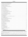
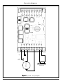
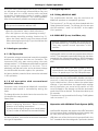
3.2 General circuit diagram
Figures 2 and 3 show the general connection scheme
of LokSoundXL decoders:
The left terminal block (No. 1) has all connections that
are needed for driving- and sound operation. The
right terminal (No. 2) is only needed for function
outputs.
Never mix up those two terminal blocks and always
make sure the connections are correct. If you connect
it the wrong way you may destroy the module.
Connect right rail to terminal 1-1, connect left rail to
terminal 1-2.
Solder the ends of the wires or crimp them.
Use terminals 1-3, 1-4 and 1-6 for the motor. When
connecting DC or coreless motors only use terminals
1-3 and 1-6. See paragraph 3.3 and 3.4 for further
details.
Make sure that no short circuits occur while
connecting the wires to the terminals.
A wheel sensor can be connected to terminals 1-4
and 1-5. See chapter 3.9 for more details.
Make sure that the wire diameter is big enough
for the terminal (at least 0,20 mm2).
Use a suitable screwdriver.
Hold the termimals while turning the screws to
avoid pressure on the circuit board.
Check every wire for good connection (pull lightly
on the wire).
Please check all connections with an ohmmeter.
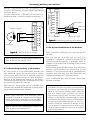
Always install a capacitor of at least 47nF in parallel to
the motor terminals. See figure 1 for an optimal
example of RFI suppression. Please note there are
several methods of RFI suppression: we recommend
to leave any suppressor (e.g. inductors) in the
locomotive.
Please check all connections with an ohmmeter,
particularly if there are any short circuits between
motor- and current pick-ups.
nF
10
147nF
10
nF
LokSoundXL User Manual V2.1 05/2002
Terminal 2 is only for lighting and special functions.
Please make sure that all outputs are connected against
terminals 2-9 (positive supply voltage). Please see
chapter 3.7 and 3.8 for details.
3.3 Connecting a DC or coreless motor
Always refer to the general wiring diagram on page 6
and bear in mind to keep any inductors connected.
For each type of motor (Buehler, Mabuchi, Faulhaber)
there are different parameters needed for load control.
They have to be adapted to optimize driving
performance (see chapter 4.2.2).
For the motor connection use terminal 1-3 and
1-6, terminals in between are not connected.
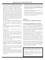
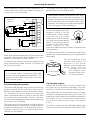
3.4 Connecting a universal motor (AC motor)
Motor
figure 1
1: RFI suppression
Connect the loudspeaker to terminals 1-8 and 1-9.
See paragraph 3.6 for installation.
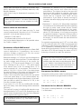
For easy conversion of older gauge-I locomotives with
universal motors (AC motor) the motors can be
directly connected to the LokSoundXL-decoder (see
Figure 4).
Connect the two motor terminals to terminals 1-3 as
well as 1-5. Exchanging both wires will change
direction of travel.
5
2-1
2-2
2-3
2-4
2-5
2-6
2-7
2-8
2-9
1-2
1-3
1-4
1-5
1-6
1-7
1-8
1-9
loudspeaker
DC-Motor
Rail
right
left
1-1
Connection diagrams
Figure 2
2: general wiring diagram
6
LokSoundXL User Manual V2.1 05/2002
LokSoundXL User Manual V2.1 05/2002
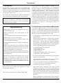
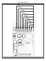
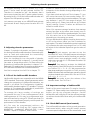
2-9
2-8
2-7
2-6
2-5
2-4
2-3
2-2
2-1
Rear lights
common voltage (U+)
AUX6 - Reed-In2
AUX5 / Reed-In1
AUX4
AUX3
AUX2
AUX1
Head lights
Connection diagrams
Figure 3
3: connecting the auxiliary functions
7
Connecting the speaker
The RFI suppression inductor remains attached to the
collector terminal of the motor. Solder the other one
to terminal 1-4 of the decoder.
Universal
motor
Rail
right
left
1-1
inductors 3,9 µH
1-2
The speaker must be installed in such a way that the
sound waves are not unduly blocked.
Please handle speakers with extreme care: don't
put pressure on or touch the membrane. The
speaker's magnets are very strong. Keep all metal
items away and secure the speaker firmly when
soldering. The soldering iron may pull the speaker
due the magnetic field and destroy it.
1-3
1-4
1-5
1-6
loudspeaker
1-7
1-8
1-9
figure 4
4: connection to Märklin® Universal motor
Solder two inductors with at least 3,9 µH to the motor
terminals. You may order these as spare parts from
Märklin® under article number 516520.
For optimal operation the motor tact frequency has
to be reduced from 22kHz to 87Hz. To achieve this
set CV 9 to value 204.
Please note:
If a universal motor is connected, Back EMF
Control will be automatically deactivated. The
principle of Back EMF Control does not work
with universal motors.
3.5 Connecting the speaker
The LokSoundXL decoder may only be used with the
speakers offered by ESU electronic solutions ulm
GmbH or with speakers with the same data (1 Watt,
16 - 32 Ohms). The use of speakers by others may
cause considerable distortion and in extreme cases
even destroy the LokSoundXL decoder. We also
cannot recommend speakers that are actually designed
for use with our H0 decoder.
The correct position of the speaker is crucial to achieve
high quality sound. A speaker that is installed without
a resonance chamber will not generate good sound.
Therefore carefully select the location and sound
chamber for the speaker.
8
Connect the speaker to the two
terminals 1-8 and 1-9 of the
LokSoundXL module. Make
sure that you use a small
soldering iron (max. 20 W) and
only heat the marked spot as
shown in the figure (close to
solder here
the edge of the small contact
plate). Polarity is not
important. Make sure that no solder is dropped onto
the membrane.
An optimal sound effect is achieved by putting the
speaker into a sound chamber, which is supplied with
the speaker.
speaker
sound chamber
This will increase the sound
pressure and channel the
direction of the sound.
Without sound chamber the
sound effect may be
unsatisfactory. Feed
the speaker wires
through a small hole in
the sound chamber.
3.6 Function outputs
LokSoundXL decoder has 8 (!) function outputs. Two
are factory-set for directional headlights, the other
six (AUX1 to AUX6) can be used for auxiliary loads.
With LokSoundXL you may dim the lamps in 15 steps
to adjust the brightness optimally to your model. The
brightness of each output may be adjusted separately.
See chapter 4.2.4.2. Every function output can be
set to various blinking light effects. See chapter
4.2.4.3.
All function outputs can be individually loaded with
0,6A current but cannot exceed a total load of 2,0A.
LokSoundXL User Manual V2.1 05/2002
Connecting headlights
If the total current exceeds 2.0A or a short circuit
occurs, then the overload protection switches
off all function outputs. Once this problem is
fixed all outputs are switched back on.
3.6.1 Connecting headlights
Connect headlights to terminal 2 as shown in figure
3. The light outputs provide the full, rectified track
voltage (between 14 and 25V depending on the type
of transformer). Therefore only use lamps for your
locomotive suitable for this voltage.
In older style locomotives you may find that lamps are
connected to the chassis. (ie.: Märklin®). In this case
don’t make a connection from the lamp back to the
terminal 2-9 and the circuit will be completed via the
chassis.
LED's or 1,5V-lamps are used in many locomotives
and can be used with LokSoundXL decoders: Use a
resistor of about 100 Ohm/0,5 Watt which has to be
soldered between function output and lamp, for each
light output that you want to connect to LED's or
1,5V-lamps. Additionally you have to lower the
brightness of the individual function output per CV.
See 4.2.4.3.
3.7 Connecting a wheel sensor
To synchronize the steam chuff an external sensor
may (but does not have to be) used. The sensor input
is terminal 1-7 on the LokSoundXL decoder. The
LokSoundXL decoder supports reed switches or
mechanical contacts as well as Hall sensors. In many
locomotives mechanical wheel sensors have been fitted
in the factory (e.g. Bachmann or Märklin®).
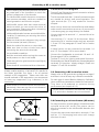
3.7.1 Connecting a reed contact with magnet
If a reed contact is to be used a miniature magnet
(available at specialized hobby shops) must be attached
to the driving wheel axle in such a way that the magnet
releases the reed contact once every turn. Miniature
reed switches have been proven to be very reliable.
They may be obtained at any electronic specialist store.
Suitable magnets may be bought at model train shops.
(e.g. Mini-track magnets) which might have to be
shaped to fit.
1-1
1-2
Miniature magnet
1-3
1-4
When using 1,5V-lamps it’s not sufficient just to
reduce the brightness per CV: for a short moment
the lamp will get the full voltage due to the used
PWM-mechanism.
1-5
1-6
1-7
1-8
3.6.2 Connecting auxiliary functions
1-9
driving axle
reed switch
You can use outputs AUX1 to AUX6 of LokSoundXL
decoders for functions such as operating a smoke
generator, switching lights, Swiss lighting mode etc.
Please note that the outputs are used for switching of
resistive loads like lamps, smoke generators, relays.
Because of possible voltage peaks due to inductivity
don’t connect the motor directly to the output, use
a relay.
Each output can be connected to terminal 2-9
or to the chassis.
Make sure that the sum of all currents for the
function outputs does not exceed the permitted
current rating and avoid short circuits between
outputs. Although outputs of LokSoundXL
decoders are protected, high voltage on the
terminals or a short circuit may cause damage.
LokSoundXL User Manual V2.1 05/2002
figure 7
7: connecting a wheel sensor
3.7.2 Connecting a mechanical contact
Many locomotives come with a factory fitted
mechanical contact that is connected to terminal 1-4
and 1-7.
All double pole (mechanical) contacts that are isolated
(not in contact with the chassis) may be used.
3.7.3 Connecting a Hall sensor
A Hall sensor is an electronic module that reacts to a
changing magnetic field (like the reed switch but more
9
Connecting auxiliary reed switches
precise.) They are easy to install. A commonly used
module is the Siemens / Infineon TLE4905 available at
electronic stores.
Connect terminal Vs of TLE4905 to terminals 1-4,
GMD to terminal 1-4 and Pin Output to terminal 1-7.
1-1
1-2
1-3
1-4
1-5
1-1
Miniature magnet
1-2
1-3
Vs
1-4
GND
1-5
Output
1-6
Reed switches
1-6
1-7
REED-IN1
1-8
REED-IN2
1-9
resistor 10k 0,25W
1-7
figure 9
9: connecting auxiliary reed switches
TLE4905
1-8
driving axle
1-9
figure 8
8: connecting a Hall sensor
Before you can use the wheel sensor certain CVs
have to be set. See chapter 5.2.4
3.7.4 Connecting auxiliary reed switches
As from version 2.0 the LokSoundXL decoder has
two additional inputs. You can use them to release
sound effects with the help of trackside magnets.
Just connect a reed sensor to the inputs and place a
magnet at the appropriate location on the layout.
The required sound effect will be activated every time
the locomotive passes the magnet.
With the aid if these inputs users of LGB MZS with
Lokmaus may activate the multitude of sound effects
generated by LokSoundXL decoders.
Both inputs REED-IN1 and REED-IN2 share
terminal 2-7 as well as 2-8 with function outputs
AUX5 and AUX6. If you want to use the REEDIN functions then AUX5 and 6 are not available.
Before you can use reed sensors certain CVs
have to be set. See chapter 5.2.7
10
4. Set Up and installation of the decoder
After successful installation you may operate the
decoder.
But first you will find out how to check your
installation. In chapter 4.1 you will find instruction of
how to operate the decoder in analogue mode. In
chapter 4.2 you learn how to operate it with various
digital systems.
Before changing any decoder settings (e.g. locomotive
address, sound volume) we recommend to read
chapter 5. There you find out which parameters are
available and how they may be altered with the
commonly available DCC command centers.
After installation you may test the LokSoundXL
decoder as follows.
Please inspect all connections carefully using an
ohmmeter: are there any short circuits between
the motor terminals and the wheel pick-ups?
Have all connections between motor terminals
and the chassis been isolated? Are bulbs
connected properly and isolated from the
chassis? Is the decoder installed safely to avoid
contact with the chassis? Is there sufficient space
around the LokSoundXL decoder to allow for
cooling? Could the LokSound 2 decoder or any
of the wires be squeezed when refitting the
housing? May sound emit from the locomotive
without obstruction?
LokSoundXL User Manual V2.1 05/2002
Analogue / digital operation
After you have checked above points you may switch
on the power. We strongly recommend to carry out
this initial test on a track section with overload
protection. Programming tracks of modern digital
systems offer this protection. Our LokProgrammer
also offers extremely reliable overload protection.
• The pre-set locomotive address is 03.
• Does the locomotive travel in both directions?
4.2 Digital operation
4.2.1 Using Märklin® 6021
The LokSoundXL decoder may be used with all
Märklin® products or compatible systems.
The functions F1 to F4 can only be activated with the
"New Motorola Format". To activate this format put
the DIP switches 1 and 2 of the 6021 to the upper
("On") position.
• Turn the lights on: are they operating correctly?
• You activate sound by pressing function key F1,
either the Diesel starts or you hear steam sounds.
When pressing function key F2 you should hear the
horn, whistle or bell, etc.
4.1 Analogue operation
4.1.1 DC Operation
DC operation using a conventional controller is possible
without any problems but has one limitation. The
locomotive will only start moving when the track
voltage reaches 7 - 8 V. Maximum speed will be reached
when turning the controller to the limit. This is
absolutely normal and is due to the minimum voltage
the LokSoundXL decoder requires for operation.
As factory default, sound effects cannot be activated
in DC operation.
4.1.2 AC operation with conventional
Märklin® controller
Operation with conventional Märklin® controllers
works as usual: speed is controlled by turning the
knob.
To change direction the knob has to be turned to the
left beyond the stop position.
Please note:
The locomotive must have completely stopped
before changing direction. Never change
direction of a moving locomotive!
Press the knob slightly longer than usual (about
0,5 sec) in order to activate the command reliably.
As factory default, sound effects cannot be used with
this type of operation.
LokSoundXL User Manual V2.1 05/2002
4.2.2 With DCC (Lenz, Intellibox, etc)
Remove capacitors that may be connected to
the track section (e.g. in ROCO connecting track).
They may impede normal operation of the
decoder.
LokSoundXL can be run with any system that conforms
to DCC. The automatic speed step detection has been
tested with the following appliances: ROCO Lokmaus
2, Uhlenbrock Intellibox, Lenz Digital plus V2.3, ZIMO
MX1.
The detection does not work properly when
operated with Lenz Digital plus V3.0 if you wish
to run 14 speed steps. Use 28/128 speed steps.
Each time that the LokSoundXL decoder receives a
current (i.e. after the system is switched on) and the
light is switched on it tries to detect the speed steps
settings. If you switchover the speed steps settings
during operation you must briefly switch off the
current supply to the decoder so that the automatic
mode functions as desired. The detection takes up to
30 seconds.
The detection can be switched off using CV 49 (please
refer to section 7.1).
Operation with LGB Multi Train System (MTS)
LokSoundXL decoders also support the LGB Command
Control system. Both Lok-Mouse and Lok-Handy may
be used, but they have to be activated first.
LGB does not utilize the function keys specified in the
DCC standards but has designed a procedure based
11
Adjusting decoder parameters
on multiple pressing of the F1 button: e.g. if you
press F1 three times this will activate function F3.
Therefore it is essential to “tell” the decoder, that it
has to count how often the F1 button makes contact.
By setting bit 6 in CV 49 the LokSoundXL decoder will
support the LGB operating mode.
Let’s assume you want to use LGB MZS and activate
load control as well. Simply enter the value 65 in CV
49.
In each CV values from 0 to 255 may be stored. The
properties of the decoder change depending on the
stored value.
If you have a look at the list of CVs in chapter 7.1 you
will notice that most CVs have number values. CV 1
for example contains the locomotive address. This may
vary between 1 and 127 (see range of values). The
factory setting is 3. Please note that not all CVs have
factory settings. Some CV values are different for
different sound effects.
Other CVs represent storage locations that manage
various functions at the same time (mostly turn on
and off). CVs 29 and 49 are good examples: for these
CVs the value has to be calculated individually,
depending on the setting you want:
5. Adjusting decoder parameters
Chapter 5 provides information on how to change
the settings of LokSoundXL decoders. Please take your
time to read and understand the occasionally
somewhat complex explanations.
After the introduction into the world of decoder
parameters (called CVs) in chapter 5.1, you will find all
you want to know about which CVs have effect the
properties of LokSoundXL decoders in chapter 5.2.
Paragraph 5.3 explains how CVs may be set with various
DCC and also the Märklin® command stations.
You find a complete list of all CVs in chapter 7.1.
5.1 CVs of the LokSoundXL decoders
LokSoundXL decoders are compatible with the NRMA
/ DCC standard. That means, that all parameters which
change the properties of LokSoundXL decoders, are
stored in so called CVs (Configuration Variables).
LokSoundXL decoders support 121 variables. This large
number of CVs shows the multitude of possibilities
available with LokSoundXL decoders
To manage this large number of settings we
recommend the use of our LokProgrammer. With
LokProgrammer all CVs may be programmed with
ease and comfort by using a PC. Please note that CVs
that are not programmed properly could impede the
performance of the decoder.
All CVs may be programmed without the
LokProgrammer by using any DCC system that is
NMRA/DCC compatible. Märklin® 6021 is also
suitable. Chapter 5.3 explains, how it works.
12
First you decide which option should to be turned on
or off. In the column "value" you find 2 numbers for
each option. The value 0 indicates the option is switched
off, otherwise the value may range from 1 to 32. Add
all values of the individual options to get the value of
the CV.
Example 1
1: Let's assume, you want to use the
Intellibox DCC with 128 speed steps and analogue
recognition should be active (because you want to
control some locos analogue mode). All other
options are turned off. CV 29 shows the value 6 (0
+ 2 + 4 + 0 = 6).
Example2
Example2: You want to activate the Märklin®
brake module, Back EMF should be activated. You
set CV 49 to 3 (1 + 2 + 0 = 3). We recommend to
deactivate analogue recognition in CV 49, since the
Märklin® brake track and analogue operation should
not be activated at the same time. You set CV 29 to
0 (0 + 0 + 0 + 0 ) = 0.
Example3
Example3: You want to turn the volume of the
decoder down. Set CV 63 to 1.
5.2 Important settings of LokSoundXL
Details of the most important CVs may be found in
chapter 5.2. Please study these instructions carefully
before you do any program changes. Careful
deliberation will help you to find the optimal settings
to achieve the desired effects with your LokSoundXL
decoder.
5.2.1 Back EMF control (load control)
The LokSoundXL decoders utilize second generation
load control which, when using DC motors, assures
constant speed independent of the actual load. Load
LokSoundXL User Manual V2.1 05/2002
How to switch on load control
control was optimized and tested with motors from
ROCO, Bachmann (Liliput), BRAWA, Märklin®, LGB,
Buehler, Mabuchi.
Load control may be deactivated completely (if so
desired).
Make sure that load control is always turned off
when using AC motors - no matter what settings
are used. AC motors are not suitable for load
control.
How to switch on load control
Set the first Bit of CV 49. Read out the CV: load
control is deactivated if the value is 0 or 2. To activate
just add 1 to the actual value and enter.
Example: CV 49 reads 2.
To activate load control set CV 49 to 3.
You find a detailed description of all possible values
for CV49 in chapter 7.1.1
Parameters of Back EMF control
The internally used PI-control algorithm of Back EMF
control depends on 3 parameters: the control
reference voltage is stored in CV 56, the control
parameters are in CVs 57 and 58.
Reference voltage: In CV 56 you set the voltage that
should come back from the motor. This value depends
on track voltage and efficiency of the motor. An
efficiency of 75 % and a track voltage of 16 V adds
up to a voltage of 16 V * 75 % = 12 V, which needs
to be written into CV 56. The voltage (here: 12 V)
may be entered in 0.1 V-increments. This results in a
value of 120 (12V * 10) for CV 56. If you don't know
the exact efficiency of the motor you may obtain the
value by the following experimental method:
Check, if the locomotive really reaches the top speed
in the last speed step or if you cannot detect any
speed changes at the higher speed steps. In the latter
case you have to reduce the value for CV 56, in the
first case increase the value.
If you enter '0" in CV 56, the LokSoundXL decoder
will find a value, from track voltage and an assumed
efficiency.
The internal PI-control of LokSoundXL decoders may
be adjusted with CV 57 and CV 58. Depending on the
type of motor the parameters may have to be adjusted
achieve optimal driving performance.
LokSoundXL decoders are factory pre-set for the
use with Bühler motors, e.g. from LGB or other
manufacturers.
LokSoundXL User Manual V2.1 05/2002
• Parameter 'K", stored in CV 57, influences how
strongly load control will effect the driving
performance. The higher the value, the more the
load control will respond to changes. Adjust this
value with consideration, because higher values
could lead to irregular and "hard" driving
performance. If you prefer a smooth running try
to reduce the value step by step until you reach an
optimum.
• Parameter "I", stored in CV 58 provides important
information to the LokSoundXL decoder regarding
the type of motor used: certain electric motors
respond differently to adjustments of the rpm's.
The longer a motor takes to respond the lower the
value in CV 58. However, it is not easy to recognize
the grade of slowness. In general: the more poles a
motor has and the bigger it is, the more fly wheels,
the slower it is and the lower the value should be
set in CV 58.
For optimal programming set CV 57 to a low value
e.g. 50. Leave the value for CV 58 ("I) unchanged and
start testing. Now change the value of CV 58 in steps
of 25 upwards or downwards and see if you get a
better driving performance. If there is no change leave
the value of CV 58 and change the value of CV 57
(intensity of control) to reach the optimum.
Please note, that incorrectly set parameters may
impede the effect of Back EMF control and
possibly cause the motor to stop altogether. Refer
to our website http://www.loksound.de for a
guide to some pre-calculated parameters for
commonly used motor / drive combinations.
Parameters for Bühler motors
Locomotives with a motor made from Bühler are used
by LGB and should be programmed as follows:
CV
CV
57 (‘K’) =
58 (‘I’) =
30
120
Parameter for for Mabuchi RS385SH
This motor is used by Märklin® in the Maxi ond Spur
1 or Bachmann.
CV
CV
57 (‘K’) =
58 (‘I’) =
50
110
13
Speed Curve
5.2.2 Speed Curve
5.2.3 Function outputs
LokSoundXL decoder has 256 speed steps. They may
be adjusted to the characteristics of each locomotive
and assigned to the available speed steps (14, 28 or
128). NMRA allows two choices:
The LokSoundXL decoder has eight physical function
outputs, two for directional headlights, the other 6
(AUX1 to AUX6) for auxiliary loads.
Speed curve via CV 2, 5 and 6 (figure 10). Set the
starting voltage in CV 2 and the maximum speed with
CV 5. CV 6 represents medium speed. You may define
the shape of the curve (straight or with two different
acceleration values). This mode is activated via CV 29
(see chapter 7.1).
256
VHigh
In addition a further 8 “functions” may be activated
by pressing a button to trigger various sound effects.
The functions “sound module on / off” and
“acceleration on / off” are available. The latter function
turns off the acceleration and deceleration and is often
used for precise control of the locomotives particularly
for shunting.
Function key assignment
128
The outputs may be assigned to the available function
keys. Each function key is linked to a CV in which any
number of events may be combined. Figure 12 shows
the different possible combinations and also the exfactory setting (marked by a dot).
VMid
Please note:
0
VStart
0
14
28
Fig. 10
10: speed curve with CV2, 6, 5
You may also define an individual speed curve: store
the speed curve values in CVs 67 to 94 (as per figure
11). Those 28 values will determine the 256 speed
steps. This method permits to optimize the driving
performance. This mode is activated when CV 29 Bit
4 is set to 1. We recommend the use of the ESU
LokProgrammer with software for easy calculation
and programming.
• Some function keys are linked to direction of travel.
• Possibly not all function keys are available on your
DCC command station.
•As many sound functions are connected with
function outputs not all function outputs and sound
functions can be set separately. You have to decide
which one you want to set. That’s why each function
output can be switched on or off separately using
a further CV.
The value that has to be entered into each individual
Control-CV is calculated as follows:
256
Add up the values of those functions that you want
to activate with the corresponding function key. Then
enter this value into the appropriate Control-CV.
128
Later we look at some examples to highlight the
process, but first we have to explain two other features
of the function outputs:
Switching on function outputs
0
Each of the three function outputs can / must be
turned on, before it can be used.
0
14
28
Fig. 11
11: Speed curve with CV 67 -90
14
You may program any of three available lighting effects
for each output:
LokSoundXL User Manual V2.1 05/2002
15
Sound on / off
Acceleration on / off
Soundslot 8
Soundslot 7
AUX6 / Soundslot 6
AUX5 / Soundslot 5
AUX4 / Soundslot 4
AUX3 / Soundslot 3
Soundslot 2
Soundslot 1
Output AUX2
Output AUX1
Output "light rear"
Output "light forward"
Control-CV
Description
Function key
Light forward
#33
1•
2
4•
64
128
16
32
F0
Light reverse
#34
1
2•
4•
64
128
16
32
F1
Key F1
#35
1
2
4
64
128
16
32•
F2
Key F2
#36
1
2
4
64 •
128
16
32
F3
Key F3
#37
1
16
32•
64
128
4
8
F4
Key F4
#38
1
16
32
64 •
128
4
8
F5
Key F5
#39
1
16
32
64
128 •
4
8
F6
Key F6
#40
1
16
32
64
128
4•
8
F7
Key F7
#41
1
2
4
8
16 •
32
64
128
F8
Key F8
#42
1
2
4
8
16
32 •
64
128
F9
Key F9 (F)
#43
1
2
4
8
16
32
64
128
F9
Key F9 (R)
#47
1
2
4
8
16
32
64
128
F10
Key F10 (F)
#44
1
2
4
8
16
32
64
128
F10
Key F10(R)
#48
1
2
4
8
16
32
64
128
F11
Key F11
#45
1
2
4
8
16
32
64
128
F12
Key F12
#46
1
2
4
8
16
32
64
128
Fig. 12 Function Mapping as per NMRA / DCC
LokSoundXL User Manual V2.1 05/2002
F0
Diming the lamps
• Dimmer: normal, continuously switched on load
• Blinking light: the output blinks with an adjustable
frequency
• Blinking light inverse: the output blinks as usual
but in opposite sequence.This permits to activate
blinking lights in opposite sequence (lamp 1 = on,
while lamp 2 = off and vice versa)
.
Starting with CV 114 each output has a CV that you
can program with the desired mode. Please note that
you may deactivate each output with "0" if not needed.
The light outputs are factory pre-set to "on". All
other function outputs AUX1 to AUX6 may be
switched off by factory default, depending on
the type of LokSoundXL-Decoder.
Dimming of lamps
With LokSoundXL you may dim the lamps in 15 steps
to adjust the brightness optimally to your model. The
lamps are pulsed, i.e.: they are continuously switched
on and off. The brightness of each output may be
adjusted separately. The desired dimming value (0 to
15) has to be added to the value of the corresponding
Control-CV (113 to 120) that defines the function
mode.
Blinking frequency and duration of "bright
phase"
If a function output has been set to "blinking" or
"blinking inverse", the duration of the "bright period"
(defines blinking frequency) and the on / off ratio
have to be taken from CV 121 (see paragraph 7.1).
The "bright period" is adjustable in 16 steps. It is always
a multiple of 0,184 sec.
The On / Off ratio is adjustable in 16 steps from 1/16
to 16/16. A ratio of 8/16 indicates that the light
output remains "on" for the same period as it is "off".
The value to be entered into the Control-CV 121 is
calculated as follows:
Duration of "On" period (value: 0 - 15) * 16 + On /
Off ratio
Examples:
• Example 1: smoke generator at AUX1 and F5.
Let's assume you want to control a smoke generator
with function key F5 that should be connected to
16
output AUX1. Please refer to the installation
instructions in chapter 2.5. The output AUX1 must
be activated and assigned to the F5 key:
First we activate the output. In this example we
want to use the dimming function (the output must
be active continuously) and set at 100% brightness.
CV 115 controls output AUX1 (see paragraph 7.1).
The value to be entered into CV 115 is calculated as
follows: 16 (for dimming function) + 15 (for
maximum brightness) = 31.
Now we have to assign function key F5 to output
AUX1: see figure 12: Control-CV 39 controls the
F5 key (third column). In CV 39 we enter those
functions that should be switched with the F5-key.
We look at the table in figure 12, locate the
intersection of the row for F5 and column AUX1
and find the number (in this case 1). Once we enter
this value in CV 39 the F5key controls the output
AUX1.
• Example 2: blinking light at AUX6 and F8
We want to connect a “blinking light” to AUX6 and
control it via the F8 function key. The brightness
should be set to 6/15 of the maximum value. The
“bright period” and the “on / off” ratio are set as
described before
First we have to activate output AUX6 and set it to
“blinking”. We achieve this by entering 32 (for
blinking) + 5 (= 6/15 of maximum brightness) =
37 in CV 120.
Next we assign output AUX6 to the F8 key. We
enter the functions to be controlled via F8 into CV
42. Again we consult the table in figure 12, find
the intersection between row F8 and column AUX6
and enter the number from the table in CV 42 (in
this case 32). Now the F8 key controls the output
AUX6
Please note that sound slot 6 and AUX6 output
are coupled: both the blinking light and sound,
memorized in sound slot 6, are activated and can
easily be modified using the LokProgrammer and
a PC.
• Example 3: Deceleration on / off with F5
Here we want to activate / deactivate the
acceleration/deceleration with F5. This function
represents a "logical" function and not a "physical"
output and thus does not have to be configured.
We only have to assign function "deactivate
deceleration" to the F5 key by entering value 4 in
CV 39 (see figure 12)
LokSoundXL User Manual V2.1 05/2002
Sound adaption
We recommend a PC and LokProgrammer for
programming function outputs: the LoksoundXLDecoder offers so many possible combinations that it
is difficult to manage these without a computer.
5.2.4 Sound adaptation
LokSoundXL decoders offer many possibilities to adjust
the sound effects. All parameters are stored in CVs
that, like all others, may be modified.
Adaptation of revolutions for diesel and pitch for
steam
The revolutions of a diesel motor may be modified
with 2 CVs:
• Enter the revolutions of the idling diesel motor in
CV 50. The standard value of 128 permits
reproduction of the sound at original speed, while
value 64 reduces this to half speed.
• Enter the revolutions at maximum speed in CV 51:
value 255 means double the original speed.
Use the same parameters when adapting the pitch of
the chuffs for steam locomotives: the interval of the
chuffs should be shorter and vary in pitch with
increasing speed.
Settings for diesel or electric locomotives
To simulate a diesel or electric locomotive the CVs 52
and 53 have to be set to 0.
Special settings for steam locomotives
To simulate a steam locomotive you have to
synchronize the steam chuffs with the revolutions of
the driving wheels. There are 2 ways:
• With an external wheel sensor
sensor the next steam chuff will be reproduced.
Normally one chuff per pulse should be played,
therefore CV 53 should read "1".
Speed step dependent method
With this method the interval between chuffs is set
with CV 52 and CV 53. This method is recommended
if an external wheel sensor cannot be used. The
adaptation of this variable to the combination of wheel
/ gearbox may require some tests. It pays to spend
some time in order to achieve an optimal result. This
feature works best with Back EMF control. With
Märklin® locomotives with universal motor (Back EMF
is always switched off) only a compromise may be
reached. In this case we recommend the use of an
external wheel sensor.
For CV adaptation proceed as follows:
• Set CV 52 to 100 and CV 53 to 200.
• Put the locomotive onto the track and drive with
speed step 1 (sound is switched on).
• Measure the time it takes in seconds for the driving
wheel to do one turn at this speed.
• Divide the time by 0,04608.
• Enter a rounded value without decimal points in CV
52.
• Increase the speed and check whether the chuffrhythm matches the turns of the drivers. If the
chuff is too fast, increase the value in CV 53
gradually, if it is too slow, decrease the value in
CV 53.
Adjusting the volume
The volume of LokSoundXL decoders may be adapted
in 3 steps:
Enter the desired value in CV 63.
Permitted values are: 0 (quiet), 1 (medium), 2 (loud).
• Speed step dependent
Depending on the method selected, certain CVs have
to be set accordingly. LokSoundXL is factory pre-set
to speed step depend adjustment.
Using the wheel sensor
The wheel sensor must be connected as described in
chapter 3.7.3 Then two more settings have to be
done: set CV 52 to value 255 and enter a value > =1
in CV 53. CV 53 defines after how many pulses by the
LokSoundXL User Manual V2.1 05/2002
Random sound effects
CV 54 and CV 55 define the frequency of random
sounds that are played while a steam locomotive is
stationary. CV 54 contains the minimal time between
2 random sounds, CV 55 the maximum. Both
represent an interval in which LokSoundXL randomly
selects and plays sounds. The units of both CVs are
0.184 seconds.
Example: the minimum interval in CV 54 should be
1.5 seconds. Enter 1.5 / 0.184 = 8 into CV 54.
17
Brake sections / Reed switch inputs
5.2.5 Brake sections
The LokSoundXL decoder responds to the two most
commonly used brake generators, which are:
• Lenz and ROCO brake generators in DCC operation
• Märklin® brake track
As soon as the LokSoundXL decoder recognizes a
brake command it brakes with a deceleration, which
may be set independently. After this forced stop the
locomotive begins to move again and accelerates to
the previously set speed. The acceleration may be
programmed separately from the standard acceleration
/ deceleration value (CV 61 and CV 62).
This feature is activated in CV 49.
Lenz LG100 / ROCO 10763
No settings are required. Both brake generators use
the mechanisms recommended by the NMRA
standards. They are always supported by LokSoundXL
decoders. n.
Märklin® brake track
Instead of digital signals the Märklin® brake track
supplies a DC voltage to the tracks. To activate this
you must set bit 1 in CV 49.
Do not activate the Märklin® brake track and
the analogue DC operation at the same time,
because the DC of the Märklin® brake track could
be interpreted as analogue DC operation. With
CV 29 you may switch off the analogue mode
(see paragraph 7.1).
5.2.7 Reed switch inputs
*** new for version 2.0 ***
In order to activate special sound effects two inputs
may be connected to reed contacts.
Typically this would be used to activate sound effects
without using the command control station. If you
install a magnet at a level crossing and a reed switchon
the locomotive chassis, it is possible to configure the
LokSoundXL decoder in such a way that every time
the locomotive passes the crossing the whistle will be
activated.
The inputs REED-IN1 and REED-IN2 share the
terminals 2-7 and 2-8 with AUX5 and AUX6. Therefore
you can only use either the inputs or the outputs but
not both at the same time.
These inputs work as follows: If a contact is closed (by
a magnet) then the effect is the same as if a function
key had been pressed. For REED-IN1 this may be F5
or F9, for REED-IN2 it could be F6 or F10.
The effect you have set to be activated by the
respective function key will now also be activated by
the reed contact. How to allocate certain functions
to specific function keys is described in section 5.2.3.
To activate REED-IN1 and REED-IN2 use CV 119 and
120. Depending on which function key should activate
which input the appropriate value has to be entered
in the CVs.:
Input
Key
Control-CV
Value
REED-IN1
F5
CV 119
14
REED-IN1
F9
CV 119
15
REED-IN2
F6
CV 120
14
REED-IN2
F10
CV 120
15
Fig. 13: Values for CV 119 and CV 120
Examples:
Let’s assume, you want to activate a whistle via REEDIN1. The appropriate sound is stored in sound slot 1.
This simulates pressing the function key F5.
Enter 14 in CV 119. Then allocate the whistle (sound
slot 1) to function key F5 (respectively to REED-IN1).
CV 39 controls F5 (refer to fig. 12 on page 26). To
activate sound slot 1 set CV 39 to 16.
Let’s assume, you want to activate the bell via REEDIN2. This sound effect is stored in sound slot 2. This
simulates pressing function key F6.
Enter 14 in CV 120. Then allocate the bell (sound slot
2) to function key F6 (respectively to REED-IN2). CV
40 controls F6. To activate sound slot 2 set CV 40 to
32.
How to connect these reed contacts has been
described in section 3.7.4. The following explains how
to set the decoder for this application.
18
LokSoundXL User Manual V2.1 05/2002
Adjusting CV’s using DCC systems
5.3 Adjusting CVs
After having been introduced to the effects controlled
by CVs in paragraph 5.1 and 5.2 we now need to
clarify how to set the CVs. There are 3 possibilities:
• With a PC and LokProgrammer
• With a DCC compatible digital command station
(e.g. Intellibox, Lenz digital plus)
• With Märklin® 6021
Depending on the product used the procedure varies.
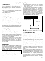
• Programming is not possible. The Lenz command
station displays "err02", the Arnold command
station "short circuit":
This is caused by the overload protection of the digital
system, which is very sensitive. The LokSoundXL
decoder with the built in audio amplifier uses a higher
current than other decoders and thus activates the
overload protection of the systems. To rectify this,
solder a resistor with 47 ohm (0,5 Watt) in one of the
two wires, connecting the digital command station
with the programming track. See figure 13.
5.3.1 Using LokProgrammer
The LokProgrammer by ESU electronic solutions ulm
GmbH offers the easiest method to modify CVs of all
LokSound decoders: with a click of the mouse using
MS-Windows®. The PC helps you to find the various
CV numbers and values. With the LokProgrammer
you can also modify the sound effects of LokSoundXL
decoders and you may create your own sound effects.
Programming track
Resistor 47Ω
You may purchase the LokProgrammer at Model Train
outlets complete with detailed operating instructions.
command station
5.3.2 Using DCC systems
There is no "one fits all" instruction for programming
of CVs with various DCC systems. There are too many
differences between the popular DCC systems.
Whenever possible you should use the DCC direct mode
(CV programming by setting individual bytes with
Uhlenbrock) or DCC paged mode.
Refer to chapter 9 "programming" of the user manual
for the Intellibox. In particular read chapter 9.5
"programming of DCC decoders" very carefully.
Programming should be done in the "CV-programming
byte-wise" mode.
Lenz digital plus
There are various software versions available of the
Lenz digital plus command station. You need firmware
version 2.3 or higher in order to program LokSoundXL
decoders. Contact Lenz for more details regarding
upgrades of older versions.
Use "paged CV" mode for programming.
Depending on the firmware version the "CV
mode" might cause problems.
Older command stations such as "Digital plus", "Lenz
compact" and "Arnold Digital" create another
phenomenon:
LokSoundXL User Manual V2.1 05/2002
Fig. 14
14: Lenz command station with 47Ω resistor
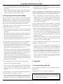
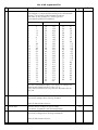
5.3.3 Using Märklin® 6021
With the Märklin® command station you cannot
modify standard CVs as it does not comply with the
NMRA DCC standards. However, the most important
CVs of LokSoundXL decoders may be changed with a
specific programming mode, described as follows:
You cannot program the 6021 with the CV concept
because only values from 01 to 80 may be entered
with this command station. That's why we call values,
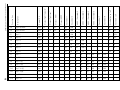
which may be modified with the 6021 "registers". Each
of the 64 registers responds to a DCC standard CV.
Figure 14 shows a list of the register numbers and
their CV numbers.
If you want to change a certain CV you have to look
up the register number first in figure 14 and then
modify it.
Many CVs have three digit values, however, the 6021
only allows a two digit input. The LokSoundXL decoder
overcomes this problem by multiplying the entered
value with a factor. The result will be memorized
internally. See figure 14for the appropriate multiplier.
That means that not all functions of the LokSoundXL
decoder may be adjusted with Märklin® command
stations.
19
Adjusting CV’s using Märklin® 6021
Programming mode of 6021
Set decoder into programming mode before entering
any changes with the 6021. Only then may the register
be selected and the new value entered and confirmed.
Once you have modified all parameters you want to
change, exit the programming mode with register
"80".
Peep sounds, varying in pitch and length, indicate
which mode you are currently using. That keeps you
in control:
Peep sounds, varying in pitch and length, indicate the
various modes of LokSoundXL decoder:
a) Register input mode (01 to 64 or 80)
•
•
•
(short, low tones, long intervals)
b) value input mode (01 to 80)
••
••
•• (combination from long / short
tones, high frequency)
c) Confirmation
(long, high tone)
Make sure that not only the track- and motor
connections are installed properly but also the speaker,
since the speaker provides the acoustic signals.
• The regulator must be set to 0.
• Take all other locomotives off the track.
• Listen to the sound signals of the locomotive.
To get into programming mode:
• Press the "stop" and "go" keys simultaneously on
6021 to activate a reset (or pull the plug of the
power pack).
• To switch off the track voltage, press the "stop" key.
• Enter the current decoder address (alternative "80").
• Activate the change of direction feature (turn the
control knob far left until you hear a "click"), hold
the knob in position and press the "go"-key.
• The LoksoundXL decoder is now in register input
mode.
• Enter the register number you want to change.
Make sure you always enter a two digit number
(e.g. "01" and not "1")
• To confirm any entry turn the knob far left (change
of direction feature). The decoder is now in value
input mode.
• Now enter a new value for the register as a two
digit number. Bear in mind that this value is
20
multiplied with the factor given for each register in
figure 11.
Note that you may only enter values 01 to 80
with the 6021. Value "0" is missing, enter instead
"80".
•Turn the knob far left to confirm. You hear a long,
high tone.
Fig.14 register values for 6021
Register
CV
RegisterCV
description
multiplicator
01
64
Märklin Address
02
2
VStart
03
6
VMid
04
5
VHigh
05
3
Acceleration rate
06
4
Deceleration rate
07
61
Acceleration rate signal section
08
62
Deceleration rate signal section
09
57
Load control parameter K
10
58
Load control parameter I
11
50
Sound Speed Min
12
51
Sound Speed Max
13
52
Sound Steam 1 (chuff)
14
53
Sound Steam 2 (chuff)
15
63
Volume (Speaker)
16
9
Motor PWM
17
56
Regulation reference
18
11
Packet Time-Out
19
60
Analogue VStart
20
13
Analogue Function status 1
21
14
Analogue Function status 2
22
29
Configuration data
23
49
Control data
24
33
Output location FL(f)
25
34
Output location FL(r)
26
35
Output location F1
27
36
Output location F2
28
37
Output location F3
29
38
Output location F4
30
66
Forward trim
31
95
Reverse trim
60
112
Braking sound Level
61
121
Flash light
62 - 64113-115Output Config Light - AUX
80
End of programming mode
1
1
4
4
1
1
1
1
4
4
4
4
4
4
1
1
4
4
1
1
1
1
1
1
1
1
1
1
1
1
1
1
1
1
LokSoundXL User Manual V2.1 05/2002
Frequently asked questions (FAQ)
• The LokSoundXL decoder changes again to
register input mode. Enter further CVs you want
to modify.
• Exit the programming mode by selecting register
"80" or switch the track voltage off and on (press
"stop"-key and then "go"-key on 6021).
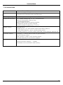
6. Frequently asked questions (FAQ)
There could be many reasons if the LokSoundXL
decoder does not work properly after installation.
Frequently there is no defect, only the various settings
do not correspond with the respective locomotive.
We list some symptoms and how to solve them:
„Lighting / sound / read and write CVs works, but
the locomotive does not move.“
• A short circuit in the motor or a high current draw
has released the overload protection of LokSoundXL
decoder.
• The motor may not be isolated from the chassis. In
this case remove the motor but do not disconnect
it and test the LokSoundXL decoder.
the table found in chapter 7.1
• A decoder-reset is easily possible with a PC and the
LokProgrammer software.
„After installing the LokSoundXL decoder the
locomotive moves in one direction at max speed
while it remains stationary in the opposite direction!?“
• This is caused by an incorrect motor connection.
Please refer to Fig. 2 and 4. Has the motor been
connected to the right terminals? They are not
located adjacent to each other, there may be inputs
or outputs in between.
I have installed LokSoundXL decoders in my LGB
locomotives. Why do functions F2 and higher not
respond when activated with the LGB-Lokhandy?
• This problem is typical for the LGB command station
and is not related to our decoder. If you press F5
for instance, then the Lokhandy transmits five times
F1 on, F1 off, F1 on, etc. The LGB decoders count
these pulses and subsequently switch the required
function output.
• Set the motor takt frequency from 22 kHz to 87
Hz when using universal motors (see CV 9).
• LokSoundXL decoders can „count“ these pulses,
but you need to enable this function first. See
section 4.2.2 for further details.
„The locomotive jerks and does not run smoothly at
low speed when Back EMF control is activated.“
„I have studied the manual, but there are still
problems. What can I do?“
• Check if the symptoms persist when you deactivate
Back EMF control (see chapter 5.2.1). If so, adjust
the motor control parameters (see 5.2.1)
• If you have further questions don't hesitate to
contact our service department. Contact details are
listed in chapter 8, on the last page of this manual.
• Possibly the motor has not been isolated against
the chassis. To eliminate this particular problem first
remove the motor and then test it. If it works you
have identified the cause of the problem.
• If you have studied this manual but feel you don't
want to proceed with the installation, esu electronic
solutions ulm GmbH can offer professional help:
Make sure there is no electrical contact between
the motor and chassis when you reinstall the motor.
This is particularly important with older motors from
Märklin® (ie: class 78).
„The locomotive runs, but there are no sounds.“
Enquire at your local hobby store for the LokSound
service pack: we install the decoder for you.
(available in Germany only)
7. Appendix
• Check the wiring to the speaker.
• The F1 key works only with the new Motorola
format when using Märklin® 6021 (see chapter
4.2.1). If this is ok, there may be damage to the
speaker.
„I would like to reset the LokSoundXL decoder to
factory settings. How does it work?“
• This is not an easy task because the factory settings
vary depending on the purchased sound version.
However, for most CV’s, a default value is given in
LokSoundXL User Manual V2.1 05/2002
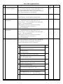
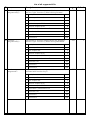
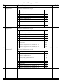
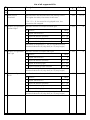
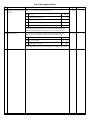
7.1 List of all supported CVs
On the following pages you will find tables with all
existing CVs.
Read about the CV concept in chapter 5.1.
Change CVs only if you have a clear understanding
of the implications. Wrong settings may damage
the LokSoundXL decoder
21
List of all supported CVs
C V name
description
range
1
Locomotive address
Address of locomotive
1 - 119
2
Start voltage
Sets the minimum speed of the locomotive
0 - 255
3
3
Acceleration
This value multiplied by 0.869 is the time
from stop to maximum speed
0 - 63
4
4
Deceleration
This value multiplied by 0.869 is the time
from maximum speed to stop
0 - 63
3
5
Maximum speed
Maximum speed of locomotive
0 - 255
63
6
Vmid
Medium speed of locomotive
0 - 255
25
7
Version number
Internal software version of LokSoundXL decoder
-
-
8
Manufacturer's ID
Manufacturer's version number (ID) of ESU
-
151
9
PWM period
Duration of PWM signal for motor control
0, 204
0
0 - 255
0
0-255
0
0-255
3
function
0
204
This value multiplied by 0.36864 is the time
after which the locomotive stops if no DCC packet is
received.
Switch off with value 0.
13 Analogue mode F1-F8 Status of functions F1 to F8 in analogue mode.
Bit Function
14 Analogue mode FL,
F9-F12
1
1 Function F2
2
2 Function F3
4
3 Function F4
8
4 Function F5
16
5 Function F6
32
6 Function F7
64
7 Function F8
128
Status of functions FL, F9 bis F12 in analogue mode.
Value
0 Function FL(f)
1
1 Function FL(r)
2
2 Function F9(f)
4
3 Function F10(f)
8
4 Function F11
16
5 Function F12
32
6 Function F9(r)
64
7 Function F10(r)
22
Value
0 Function F1
Bit Function
3
value
PWM frequency = 22000 Hz (recommended)
PWM frequency = 87 Hz (for universal motors)
11 Paket timeout time
default
128
LokSoundXL User Manual V2.1 05/2002
C V name
List of all supported CVs
description
range
default
17 Extended
18 locomotive address
long address of locomotive
CV 17 contains byte with higher value (Bit 6 and
Bit 7 must always be active), CV18 contains
byte with lower value. Only active when function
in CV 29 is switched on. (see below)
128 9999
0
19 Consist address
Additional address for consist
0 - 127
0
value 0 means: consist address deactivated
23 Acceleration
adaptation
Additional period of acceleration which is added
to or deducted from the base value (CV 3)
values from 0 - 127 are added to the base value,
values > 128 are deducted.
Mathematical: bit 0-6 represents the value,
bit 7 indicates plus (0) or minus (1)
(see DCC Standards)
0 - 255
0
24 Deceleration
adaptation
Additional period of deceleration, which is added
to or deducted from the base value (CV 4)
values from 0 - 127 are added to the base value,
values > 128 are deducted.
Mathematical: bit 0-6 represents the value,
bit 7 indicates plus (0) or minus (1)
(see DCC Standards)
0 - 255
0
-
4
29 Configuration register The most complex CV within the DCC standards.
This register contains important information,
which is only relevant in DCC operation.
Bit function
value
0 Reverse direction of travel
(forward becomes reverse)
normal direction
reversed direction
0
1
1 speed steps (only for DCC operation)
14 speed steps
28 or 128 speed steps
0
2
2 analogue operation
analogue operation switched off
analogue operation permitted
0
4
4 selection of speed curve
speed curve through CV 2,5, 6
speed curve through CV 67 - 96
0
16
5 selection of locoaddress (only for DCC operation)
short addresses (CV 1) in DCC operation
long addresses (CV 17 + 18) in DCC operation
LokSoundXL User Manual V2.1 05/2002
0
32
23
List of all supported CVs
C V name
description
range
33 FunctionassignmentFL(f)
Assignment of function outputs, which are activated
with the "light" function (f) when driving forward
0 - 255
1
0 - 255
2
0 - 255
32
Bit description
34 FunctionassignmentFL(r)
value
0 light output forward
1
1 light output rear
2
2 function output AUX1
4
3 function output AUX2
8
4 acceleration / deceleration off
16
5 sound on / off
32
6 sound slot 1
64
7 sound slot 2
128
Assignment of function outputs which are activated
with the "light" function (f) when driving backwards
Bit description
35 Function
assignmentF1
24
value
0 light output forward
1
1 light output rear
2
2 function output AUX1
4
3 function output AUX2
8
4 acceleration / deceleration off
16
5 sound on / off
32
6 sound slot 1
64
7 sound slot 2
128
Assignment of function outputs, which are
activated with function key F1
Bit description
default
value
0 light output forward
1
1 light output rear
2
2 function output AUX1
4
33 function output AUX2
8
4 acceleration / deceleration off
16
5 sound on / off
32
6 sound slot 1
64
7 sound slot 2
128
LokSoundXL User Manual V2.1 05/2002
List of all supported CVs
C V name
description
range
36 Function
assignment F2
Assignment of function outputs, which are
activated with function key F2
0 - 255
64
0 - 255
32
0 - 255
64
Bit description
1
1 light output rear
2
2 function output AUX1
4
3 function output AUX2
8
4 acceleration / deceleration off
16
5 sound on / off
32
6 sound slot 1
64
128
Assignment of function outputs, which are
activated with function key F3
Bit description
value
0 function output AUX1
1
1 function output AUX2
2
2 acceleration / deceleration off
4
3 sound on / off
8
4 sound slot 1
38 Function
assignment F4
value
0 light output forward
7 function output AUX4 / sound slot 2
37 Function
assignment F3
16
5 sound slot 2
32
6 function output AUX3 / sound slot 3
64
7 function output AUX4 / sound slot 4
128
Assignment of function outputs, which are
activated with function key F4
Bit description
value
0 function output AUX1
1
1 function output AUX2
2
2 acceleration / deceleration off
4
3 sound on / off
8
4 sound slot 1
16
5 sound slot 2
32
6 function output AUX3 / sound slot 3
64
7 function output AUX4 / sound slot 4
128
LokSoundXL User Manual V2.1 05/2002
default
25
List of all supported CVs
C V name
description
range
39 Function
assignment F5
Assignment of function outputs, which are
activated with function key F5
0 - 255
0
0 - 255
0
0 - 255
0
Bit description
40 Function
assignment F6
value
0 function output AUX1
1
1 function output AUX2
2
2 acceleration / deceleration off
4
3 sound on / off
8
4 sound slot 1
16
5 sound slot 2
32
6 function output AUX3 / sound slot 3
64
7 function output AUX4 / sound slot 4
128
Assignment of function outputs, which are
activated with function key F6
Bit description
41 Function
assignment F7
26
value
0 function output AUX1
1
1 function output AUX2
2
2 acceleration / deceleration off
4
3 sound on / off
8
4 sound slot 1
16
5 sound slot 2
32
6 function output AUX3 / sound slot 3
64
7 function output AUX4 / sound slot 4
128
Assignment of function outputs, which are
activated with function key F7
Bit description
default
value
0 sound slot 1
1
1 sound slot 2
2
2 function output AUX3 / sound slot 3
4
3 function output AUX4 / sound slot 4
8
4 function output AUX5
16
5 function output AUX6
32
6 sound slot 7
64
7 sound slot 8
128
LokSoundXL User Manual V2.1 05/2002
List of all supported CVs
C V name
description
range
42 Function
assignment F8
Assignment of function outputs, which are
activated with function key F8
0 - 255
0
0 - 255
0
0 - 255
0
Bit description
43 Function
assignment F9(f)
44 Function
assignment F10(f)
value
0 sound slot 1
1
1 sound slot 2
2
2 function output AUX3 / sound slot 3
4
3 function output AUX4 / sound slot 4
8
4 function output AUX5
16
5 function output AUX6
32
6 sound slot 7
64
7 sound slot 8
128
Assignment of function outputs, which are
activated with function key F9 when driving forward
Bit description
value
0 sound slot 1
1
1 sound slot 2
2
2 function output AUX3 / sound slot 3
4
3 function output AUX4 / sound slot 4
8
4 function output AUX5
16
5 function output AUX6
32
6 sound slot 7
64
7 sound slot 8
128
Assignment of function outputs, which are
activated with function key F10
Bit description
value
0 sound slot 1
1
1 sound slot 2
2
2 function output AUX3 / sound slot 3
4
3 function output AUX4 / sound slot 4
8
4 function output AUX5
16
5 function output AUX6
32
6 sound slot 7
64
7 sound slot 8
128
LokSoundXL User Manual V2.1 05/2002
default
27
List of all supported CVs
C V name
description
range
45 Function
assignment F11
Assignment of function outputs, which are
activated with function key F11
0 - 255
0
0 - 255
0
0 - 255
0
Bit description
46 Function
assignment F12
47 Function
assignment F9(r)
1
1 sound slot 2
2
2 function output AUX3 / sound slot 3
4
3 function output AUX4 / sound slot 4
8
4 function output AUX5
16
5 function output AUX6
32
6 sound slot 7
64
7 sound slot 8
128
Assignment of function outputs, which are
activated with function key F12
value
0 sound slot 1
1
1 sound slot 2
2
2 function output AUX3 / sound slot 3
4
3 function output AUX4 / sound slot 4
8
4 function output AUX5
16
5 function output AUX6
32
6 sound slot 7
64
7 sound slot 8
128128
Assignment of function outputs, which are
activated with function key F9 when driving backwards
Bit description
28
value
0 sound slot 1
Bit description
default
value
0 sound slot 1
1
1 sound slot 2
2
2 function output AUX3 / sound slot 3
4
3 function output AUX4 / sound slot 4
8
4 function output AUX5
16
5 function output AUX6
32
6 sound slot 7
64
7 sound slot 8
128
LokSoundXL User Manual V2.1 05/2002
List of all supported CVs
C V name
description
range
48 Function
assignment F10(r)
Assignment of function outputs, which are
activated with function key F9 when driving backwards
0 - 255
Bit description
49 Extended
configuration
50 Sound Min
0
value
0 sound slot 1
1
1 sound slot 2
2
2 function output AUX3 / sound slot 3
4
3 function output AUX4 / sound slot 4
8
4 function output AUX5
16
5 function output AUX6
32
6 sound slot 7
64
7 sound slot 8
128
Activate support for brake track sections
or switch off Back EMF control
Bit description
default
5
value
0 load control activated
1
1 Märklin brake track activated
2
3 DCC Automatic Speed Step Detection activated
32
4 function key interpretation according to
LGB MTS System
64
Divided by 128 this will yield the factor for
reproducing the sound at the slowest speed step.
0 - 255
128
0 - 255
128
0 - 255
steam: 90
diesel: 0
values < 128 are slower, values > 128 are
faster than original speed
51 Sound Max
Divided by 128 this will yield the factor for
reproducing the sound at the fastest speed step.
values < 128 are slower, values > 128 are
faster than original speed
52 Sound mode 1
Multiplied by 0,04608 is the time in seconds
between two chuff sounds at speed step 1
value 0 deactivates steam sound
and changes to diesel sound
electric: 0
value 255 indicates that period between chuffs is
controlled by a wheel sensor
53 Sound mode 2
Value defines the gradual decrease of intervals of
chuffs with increasing speed. A higher
value indicates a more rapid decrease,
a lower value a slower decrease.
0 - 255
steam: 200
diesel: 0
electric: 0
in diesel mode (CV 52 = 0): CV 53 = 0
If a wheel sensor is used (CV 52 = 255),
then this value specifies the number of pulses needed
to trigger on chuff.
LokSoundXL User Manual V2.1 05/2002
29
List of all supported CVs
C V name
description
range
54 Random sound min
Multiplied by 0,18432 is the time in seconds
for the shortest random sound interval.
These values represent the interval between
random sounds.
0 - 255
default
20
55 Random sound max
Multiplied by 0,18432 is the time in seconds
for the longest interval between random sounds.
These values represent the interval between
random sounds.
0 - 255
60
Defines the Back EMF voltage, which the motor
0 - 255
should generate at maximum speed.
The higher the efficiency, the higher this value may be set.
If the locomotive does not reach maximum speed,
reduce this parameter.
145
Playing of random sounds is deactivated when
CV 53 and CV 54 = 0
56 Motor control
reference
If CV 56 is set to = 0 ist, the decoder measures the
track voltage and takes a fraction of this value for the
reference.
57 Load control
K-segment
„K“-segment of internal PI-controller
Defines the effect of load control. The higher the value,
the stronger the effect of Back EMF control
0 - 255
30
58 Load control
I-Segment
„I“-segment of internal PI-controller
0 - 255
Defines momentum of motor. The higher the momentum
of the motor (large flywheel or bigger diameter motor)
the lower this value has to be set
(see chapter 5.2.1)
120
60 Analogue
start voltage
Start voltage of motor in analogue operation
0 - 255
61 Acceleration
signal track
Value multiplied by 0.869 is the time from
stop to maximum speed
0 - 64
8
62 Deceleration
signal track
Value multiplied by 0.869 is the time from
maximum speed to stop
0 - 64
4
63 sound volume
0 = low, 1 = medium, 2 = loud
0,1, 2
2
30
25
LokSoundXL User Manual V2.1 05/2002
List of all supported CVs
C V name
description
range
64 Märklin® address
Address of decoder in Motorola® operation.
The address is interpreted according to the Motorola®
format. The following table shows the values,
that have to be entered in CV64 to get the
corresponding Märklin® address
0 - 255
12
0 - 255
0
address value
address value
address value
1
2
3
4
5
6
7
8
9
10
11
12
13
14
15
16
17
18
19
20
21
22
23
24
25
26
27
28
29
30
31
32
33
34
35
36
37
38
39
40
41
42
43
44
45
46
47
48
49
50
51
52
53
54
55
56
57
58
59
60
61
62
63
64
65
66
67
68
69
70
71
72
73
74
75
76
77
78
79
80
3
1
12
15
13
4
7
5
48
51
49
60
63
61
52
55
53
16
19
17
28
31
29
20
23
21
192
195
193
204
207
205
196
199
197
240
243
241
252
255
253
244
247
245
208
211
209
220
223
221
212
215
213
64
default
67
65
76
79
77
68
71
69
112
115
113
124
127
125
116
119
117
80
83
81
92
95
93
84
87
85
You don't need above table if you want to change the
address with Märklin® 6021 (see 5.3.3):
Enter desired address directly and the decoder will do
the rest.
66 Forward trim
Divided by 128 is the factor used to multiply
the motor voltage when driving forward.
Value 0 deactivates the trim
67- Speed Table
94
Defines motor voltage for speed steps.
The values "in between" will be interpolated.
0 - 255
---
95 Reverse trim
Divided by 128 is the factor used to multiply
the motor voltage when driving backwards.
0 - 255
0
Value 0 deactivates the trim
LokSoundXL User Manual V2.1 05/2002
31
List of all supported CVs
C V name
description
range
default
105 User ID
106
Available to the user for any data
0 - 255
0
112 Brake sound
threshold
Specifies when the decoder starts the braking noises.
The higher the value, the sooner it will start.
0 - 255
0 / 12
0 - 255
31
0 - 255
31
0 - 255
31
If CV 112 = 0, the sound is only played once the
locomotive has stopped.
113 Output configuration Specifies function of output forward light
forward light
Bit function
value
-
Output switched off
-
Output as dimmer (normal)
Vol + 16
0
-
Output as blinking light
Vol + 32
-
Output is blinking light reversed
Vol + 48
Add values of brightness (= Vol) to the values above.
Permitted values are 0 (very dark) to 15 (very bright)
114 Output configuration Specifies function of output rear light
rear light
Bit function
value
-
Output switched off
0
-
Output as dimmer (normal)
Vol + 16
-
Output as blinking light
Vol + 32
-
Output is blinking light reversed
Vol + 48
Add values of brightness (= Vol) to the values above.
Permitted values are 0 (very dark) to 15 (very bright)
115 Output configuration Specifies function of output AUX1
AUX1
Bit function
value
-
Output switched off
0
-
Output as dimmer (normal)
Vol + 16
-
Output as blinking light
Vol + 32
-
Output is blinking light reversed
Vol + 48
Add values of brightness (= Vol) to the values above.
Permitted values are 0 (very dark) to 15 (very bright)
32
LokSoundXL User Manual V2.1 05/2002
List of all supported CVs
C V name
description
116 Output configuration Specifies function of output AUX2
AUX2
Bit function
range
default
0 - 255
31
0 - 255
31
0 - 255
31
0 - 255
31
value
-
Output switched off
-
Output as dimmer (normal)
Vol + 16
0
-
Output as blinking light
Vol + 32
-
Output is blinking light reversed
Vol + 48
Add values of brightness (= Vol) to the values above.
Permitted values are 0 (very dark) to 15 (very bright)
117 Output configuration Specifies function of output AUX3
AUX3
Bit function
value
-
Output switched off
-
Output as dimmer (normal)
Vol + 16
0
-
Output as blinking light
Vol + 32
-
Output is blinking light reversed
Vol + 48
Add values of brightness (= Vol) to the values above.
Permitted values are 0 (very dark) to 15 (very bright)
118 Output configuration Specifies function of output AUX4
AUX4
Bit function
value
-
Output switched off
-
Output as dimmer (normal)
Vol + 16
0
-
Output as blinking light
Vol + 32
-
Output is blinking light reversed
Vol + 48
Add values of brightness (= Vol) to the values above.
Permitted values are 0 (very dark) to 15 (very bright)
119 Output configuration Specifies function of output AUX5
AUX5
Bit function
value
-
Output switched off
-
Output as dimmer (normal)
Vol + 16
0
-
Output as blinking light
Vol + 32
-
Output is blinking light reversed
Vol + 48
Add values of brightness (= Vol) to the values above.
Permitted values are 0 (very dark) to 15 (very bright)
LokSoundXL User Manual V2.1 05/2002
33
List of all supported CVs
C V name
description
120 Output configuration Specifies function of output AUX6
AUX2
Bit function
range
default
0 - 255
31
0 - 255
0
value
-
Output switched off
-
Output as dimmer (normal)
Vol + 16
0
-
Output as blinking light
Vol + 32
-
Output is blinking light reversed
Vol + 48
Add values of brightness (= Vol) to the values above.
Permitted values are 0 (very dark) to 15 (very bright)
121 Blinking light
Specifies the duration of the "bright period" and the
on/off ratio of outputs, which are set to blinking
Bit function
0-3 On / Off ratio
4-7 PWM period time
value
0 - 15
16 - 240
The PWM period time is a multiple of 0.18432 seconds.
34
LokSoundXL User Manual V2.1 05/2002
Technical data
7.2 Technical data
Dimensions:
44 mm x 40 mm x 6,5mm
Layout:
Double-sided PCB with SMD-technology.
Connection of all functions with screw terminals
Operating voltage:
5 to 25 V / pulse for change of direction 32 Volts
Supported protocols:
DCC / NMRA-standard wth 14, 28, 128 speed steps
Märklin® / Motorola® (old and new)
2- and 4-digit addresses
Märklin® and Lenz LG100 braking modules
Analogue DC and AC operation possible
Operations Mode Programming, F1 to F12
Motor control:
max load 3.0 A
Suitable for DC-, AC- and coreless motors (auto detect feature)
22 kHz PWM frequency - quiet, smooth motor control
overload protoection of motor output, Back EMF control (may be switched off)
Function outputs:
8 Outputs, 2 of which may be used for light functions
600 mA load per output.
Total current of 2 Amp. for all function output.
Overload protection for all function outputs
Sound part:
two independent channels
High performance amplifier, ~ 3 Watts
Sound data can be modified in flash memory
LokSoundXL User Manual V2.1 05/2002
35
Service and Support
8. Service-Support and assistance
Your model train or hobby shop is your competent
partner for all your questions regarding LokSoundXL
decoders.
You may also contact us directly. For enquiries please
use either email or fax (don't forget to provide your
own fax-no.) and we will reply within a few days.
Please call our hotline only in case of complex
enquiries that can't be dealt with by email or fax.
The hotline is often very busy you may encounter
delays. Also check our website for more
information. You will find many hints regarding
FAQ and even feed back from other users.
by phone:
++49 (0)700 - LOKSOUND
++49 (0)700 - 56576863
Tue from 10am to 12am
Wed from 10am to 12am
by Fax :
++49 (0)7043 - 90 75 36
by email:
[email protected]
by mail:
ESU electronic solutions ulm GmbH
- technischer Support Am Tiefen See 5
D-75433 Maulbronn
Internet:
www
.loksound.de
www.loksound.de
printed in Germany
36
LokSoundXL User Manual V2.1 05/2002