1
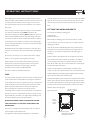
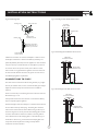
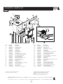
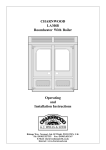
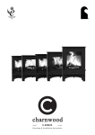
®
charnwood
country
4
MKII
Operating & Installation Instructions
CONTENTS
O P E R AT I N G I N S T R U C T I O N S
Fuel
4
Fitting The Riddling Grate
4
Lighting
5
Controlling The Fire
5
Refuelling
5
Ash Clearance
6
Reduced Burning
6
Cleaning and Maintenance
6
Throat Plate & Flueway Clearing
6
Chimney Sweeping
6
Servicing
7
Trouble Shooting
7
CO Alarm
8
If you need further help
8
INSTALLATION INSTRUCTIONS
Health & Safety Precautions
10
CO Alarms
10
Specification
10
Chimney
10
Hearth & Fire Surround
10
Connection to Flues
11
Soot Doors
12
Pre Lighting Check
12
Commissioning
12
Dimensions
13
Parts Lists
14
Certification
15
Ref. Country 4 v2 MKII 06.13
charnwood
OPERATING INSTRUCTIONS
®
Before lighting the stove check with the installer that the work and
operating appliance for burning dry seasoned wood logs only. HETAS
checks described in the Installation Instructions have been carried out
approval does not cover the use of other fuels either alone or mixed
correctly and that the chimney has been swept, is sound and free
with wood logs nor does it cover the instructions for use of other
from any obstructions. The stove is not suitable for use in a shared
fuels.
flue system.
If you are using your stove to burn wood logs in a smoke controlled
FITTING THE RIDDLING GRATE
area, then the Smoke Reducing Kit MUST be fitted and the
Tool required for fitting the riddling grate:
instructions on lighting and refuelling MUST be followed. This stove
10mm Spanner
Pozidriv screwdriver
will not produce significant smoke if well seasoned logs of less than
20% moisture content are burnt and these instructions are adhered
Before fitting the riddling grate remove the fuel retainer and the
to. Burning wet (> 20% moisture content) wood and operating the
wood ash retainer. The wood ash retainer is not required when the
stove in an irresponsible manner may produce smoke which is illegal
riddling grate is fitted.
in smoke controlled areas.
Undo the nut on the riddling blanking hole using a 10mm spanner.
Remember that the stove will be hot and that it is made from hard
Remove the cover and spacing washer (ensure you keep these in a
materials – ensure that you have good balance before operating the
safe place as you will need to replace them if the riddling grate is
fire.
removed).
Do not use an aerosol spray on or near the stove when it is alight.
Feed the riddler rod through the hole on the right hand side of the
There is a risk of explosion or flash ignition of the spray.
stove, and slide one washer onto the rod. (If there is not sufficient
When using the stove in situations where children, aged and/or
room to the right of the stove to do this then remove the riddler
infirm persons are present a fireguard must be used to prevent
knob, fit one washer over the rod and then slide the rod through the
accidental contact with the stove. The fireguard should be
hole from the inside of the stove.)
manufactured in accordance with BS 8423:2002.
Feed the rod through the two side fireplates and slide the other
The stove is suitable for intermittent operation.
washer on to the rod so that the washers end up outside the two side
fireplates. With the side fireplates pushed together fit the retaining
FUEL
clips so that the washers come inside the clips.
This stove has been designated to burn wood. Only dry well seasoned
Slide the side fireplates apart so that they rest against the sides of the
wood should be burnt on this appliance as burning wet unseasoned
firebox. Slot in the front and rear support plates. Fit the grate plates
wood will give rise to heavy tar deposits in the stove, on the glass and
into position through the front and rear grate support plates, making
within the chimney. For the same reason hard woods (such as Ash,
sure they locate correctly onto the riddler rod. Fit the fuel retainer.
Beech and Oak) are better than soft woods (such as Pine and
Slide the ashpan under the grate.
Spruce). Burning wet unseasoned wood will also result in
Fig.1. Stove Controls
considerably reduced outputs. The wood should be cut and split and
Airwash Control
Closed
Open
then left to season in a well ventilated dry place for at least one year
but preferably two years before use. Approximate suitable log sizes
are 255mm (10in) long and 75mm (3in) diameter.
Door
Handle
Pull to
Open
PETROLEUM COKE IS NOT SUITABLE FOR USE ON
THIS APPLIANCE. ITS USE WILL INVALIDATE THE
GUARANTEE.
This stove is not designed to burn household waste. For advice on
other fuels please contact Charnwood.
This appliance has been approved by HETAS as an intermittent
4
Primary Air Control
Anti-Clockwise to Open
Clockwise to Close
charnwood
OPERATING INSTRUCTIONS
®
CONTROLLING THE FIRE
Fig.2. Optional Grate Kit
The rate of burning and hence the output is controlled by the spin
wheel and the airwash control (see Fig. 1).
Grate Plates
The spin wheel should only be used when lighting or when rapid
Fuel Retainer
burning is required. It should not be left fully open for long periods as
this can cause over-firing. For low burning it should be closed.
Rear Grate
Support
Front Grate
Support
The airwash control is used most of the time to control the burning
rate and to keep the glass clean. Fully extended gives full airwash for
LH Side
Grate
Support
faster burning and clean glass whereas fully closed gives low burning.
It will not be possible to keep the glass clean if this control is fully
closed, particularly immediately after refuelling. For correct firing we
recommend the use of a stove pipe thermometer which may be
Ashpan
Riddler
Rod
purchased from your supplier or from ourselves.
RH Side
Grate
Support
When the stove is hot, these controls must only be operated using
the tool provided or a glove to avoid the danger of burned fingers.
LIGHTING
REFUELLING
On initial lighting, the stove may smoke and give off an odour as the
Keep the firebox well filled but do not allow fuel to spill over the top
silicon paint with which the firebox is painted reacts to the heat. This
of the fuel retainer.
is normal and will cease after a short time, but meanwhile the room
Logs should be evenly distributed, filling the firebed to give the most
should be kept well ventilated.
pleasing flame pattern. The air controls must be fully opened after
At first only light a small fire and burn it slowly for two hours to allow
refuelling until the flames are established above the fire. It is best to
any residual moisture in the chimney to evaporate.
refuel on to a hot bed of ash. If at this point the fire starts to die, the
Light the stove using dry kindling wood and paper or fire lighters. Put
doors must be cracked open until the fire is revived in order that
the paper, or fire lighters, and kindling in the firebox and cover with a
smoke may not be produced. If the fire has started to die down
few small dry logs. Open the air controls – the primary air control in
before refuelling, then more kindling wood must be added, the air
the door and the airwash control - fully (see Fig. 1). Light the paper
controls opened fully and the door cracked open to re-establish the
or fire lighters. The door may be left cracked open for a few minutes
firebed before adding larger logs (see suitable log sizes in Fuel
to assist the combustion and heat up the firebox more quickly. When
section).
the kindling wood is well alight add a few more small logs, close the
Care should be taken, especially when burning wood, that fuel does
doors but leave the air controls fully open. When the flames are
not project over the fuel retainer or damage to the glass may be
established around these logs, load the stove with the required fuel
caused when the door is closed. It can also cause the glass to blacken.
load. Maintain the air controls at maximum at this stage. Once the
Maximum filling height is such that logs cannot fall from the fire when
fire is up to temperature the airwash system will begin to work, so
the doors are opened. In smoke controlled areas do not fill the stove
allow the fire to become hot before adjusting the air controls to the
above the level of the front firebars. Liquid fuels are not to be used
required setting. During the lighting period, do not leave the stove
on this appliance.
unattended.
ASH CLEARANCE
When relighting the stove, leave the ash on the base if burning wood,
unless it is becoming too deep, in which case some of it may be
The ashpan should be emptied regularly before it becomes too full.
removed. If burning high ash content fuel, clear the grate and empty
Never allow the ash to accumulate in the ashpan so that it comes in
the ashpan before relighting.
contact with the underside of the grate as this will seriously damage
5
charnwood
OPERATING INSTRUCTIONS
®
the grate bars. The ashpan is handled using the tool provided. Care
deposits on the glass may be removed with a proprietary stove glass
should be taken to ensure that ash is cool before emptying it into
cleaner or ceramic hob cleaner. Do not use abrasive cleaners or pads
plastic liners or bins.
as these can scratch the surface which will weaken the glass and cause
premature failure
To make ash removal easier there is a special Charnwood ash carrier
THROAT PLATE AND
available. This may be purchased from your supplier or, in case of
difficulty, directly from Charnwood.
FLUEWAY CLEANING
Fig.3. Throat Plate Position and Lowering
It is important that the throat plate and all the stove flueways are kept
clean in order to prevent potentially dangerous fume emission. They
Throat Plate
should be cleaned at least monthly, and more frequently if necessary.
It is necessary to let the fire out to carry out these operations.
Pull Up
and Swing Down
The front of the throat plate is pulled forward and then lowered as
shown in Fig. 3. Any sooty deposits should then be swept from the
plate and into the fire.
Return the throat plate to its correct position - raise the front of the
plate, push it back and then lower it onto the retaining lugs.
CHIMNEY SWEEPING
REDUCED BURNING
The chimney should be swept at least twice a year. Where the top
outlet or vertical rear flue connector is used it will generally be
For reduced burning the fire door must be closed.
possible to sweep the chimney through the appliance.
When burning wood in areas that are not smoke controlled, load
First remove the fuel retainer and the throat plate. Then sweep the
some large logs on the fire and allow to burn for half an hour before
chimney ensuring that soot is removed from all horizontal surfaces
closing the spin wheel (this will help to reduce tar deposits in the
after sweeping.
chimney). Leave the airwash control slightly open to help keep the
glass clear. Some experimentation may be necessary to find the
In situations where it is not possible to sweep through the appliance
setting most suitable for the type of fuel being used and the draw on
the installer will have provided alternative means, such as a soot door.
the chimney.
After sweeping the chimney the appliance flue outlet and the flue
pipe connecting the stove to the chimney must be cleaned with a flue
To revive the fire, empty the ashpan, (if burning fuel other than
brush.
wood), riddle the fire, and open the air controls to maximum. When
the fire is burning well load on more fuel as necessary and adjust the
After clearing any soot from within the stove, replace the throat plate
air controls to the desired setting.
(see Fig. 3.) and the fuel retainer.
CLEANING AND MAINTENANCE
Different types of sweep’s brushes are available to suit different
flueways. For standard brick chimneys a wire centre sweep’s brush
The stove is finished with a high temperature paint which will
fitted with a guide wheel is recommended. For prefabricated
withstand the temperatures encountered in normal use. This may be
insulated chimneys the manufacturers instructions with regard to
cleaned with a damp lint-free cloth when the stove is cold. Should re-
sweeping should be consulted.
painting become necessary, high temperature paints are available
from your supplier or from stove shops.
SERVICING
Most deposits on the glass may be burnt off simply by running the fire
It is recommended that the fire is serviced once a year to keep it in
at a fast rate for a few minutes. If it becomes necessary to clean the
first class working order. After cleaning out the firebox thoroughly,
glass then open the door and allow it to cool. Clean the glass using a
check that all internal parts are in good working order, replacing any
damp cloth and then wiping over with a dry cloth. Any stubborn
6
parts that are beginning to show signs of wear. Check that the doors
charnwood
OPERATING INSTRUCTIONS
®
mm (0.10 inches) water gauge (25Pa) should be obtained.
seals are in good condition and that the door seals correctly. A
servicing guide is available on request. Repairs or modifications may
Some blackening of the glass may occur below the level of the coal
only be carried out by the Manufacturer or their approved agents.
retainer. This will not obscure the view of the fire or affect its
Use only genuine Charnwood replacement parts.
performance.
TROUBLE SHOOTING
Fume Emission
Warning Note:
Fire Will Not Burn
Properly installed and operated this appliance will not emit fumes.
Check that:
Occasional fumes from de-ashing and re-fuelling may occur.
a) the air inlet is not obstructed in any way,
Persistent fume emission is potentially dangerous and must not be
b) chimneys and flueways are clear,
tolerated. If fume emission does persist, then the following
c) a suitable fuel is being used,
immediate actions should be taken:
d) there is an adequate air supply into the room,
a) Open doors and windows to ventilate the room.
e) an extractor fan is not fitted in the same room as the stove.
f) there is sufficient draw in the chimney. Once the chimney is warm a
b) Let the fire out and safely dispose of the fuel from the
draught reading of at least 2.5 mm (0.10 inches) water gauge (25Pa)
appliance.
should be obtained.
c) Check for flue or chimney blockage, and clean if required.
Blackening of Door Glass
d) Do not attempt to re-light the fire until cause of fume has been
Differences in chimney draughts mean that the best settings of the air
identified, if necessary seek professional advice.
controls will vary for different installations. A certain amount of
The most common cause of fume emission is flueway or chimney
experimentation may be required. However the following points
blockage. For your own safety these must be kept clean.
should be noted, and with a little care should enable the glass to be
kept clean in most situations:
Fire blazing out of control
a) Wet or unseasoned wood, or logs overhanging the front fence will
Check that:
cause the glass to blacken.
a) The door is tightly closed.
b) The airwash relies on a supply of heated air to keep the glass clean.
b) The spin wheel is fully closed.
Therefore, when lighting the stove allow the firebed to become well
c) The airwash control is closed.
established before closing the spin wheel. This may also be necessary
d) A suitable fuel is being used.
when re-fuelling the stove.
e) Door seals and airwash slide are intact.
c) When re-fuelling keep the fuel as far back from the front fence as
Chimney Fires
possible, do not try to fit too much fuel into the firebox.
If the chimney is thoroughly and regularly swept, chimney fires should
d) Never completely close the airwash control - as a guide it should
not occur. However, if a chimney fire does occur close the spin wheel
be at least a quarter open.
and the airwash control, and tightly close the door of the appliance.
e) The spin wheel may be kept slightly open to assist in keeping the
This should cause chimney fire to go out in which case the controls
glass clean.
should be kept closed until the stove has gone out. The chimney and
flueways should then be cleaned. If the chimney fire does not go out
It is always more difficult to keep the glass clean when running the
when the above action is taken then the fire brigade should be called
stove very slowly for long periods.
immediately.
If blackening of the glass still occurs check that all flue connections
After a chimney fire the chimney should be carefully examined for
and the blanking plate are well sealed. It is also important that the
any damage. Expert advice should be sought if necessary.
chimney draw is sufficient and that it is not affected by downdraught.. When the chimney is warm a draught reading of at least 2.5
7
charnwood
OPERATING INSTRUCTIONS
®
CO Alarm
Your installer should have fitted a CO alarm in the same room as the
appliance. If the alarm sounds unexpectedly, follow the instructions
given under “Warning Note” above.
IF YOU NEED FURTHER HELP
If you need further help with your Charnwood then your Installer will
be able to provide the answers to most questions. Your Local
Charnwood Premier Dealer has a great deal of experience and will
also be able to provide helpful advice. Further help is available from
the Charnwood Customer Services department who will be pleased
to give advice, if necessary.
8
charnwood
INSTALLATION INSTRUCTIONS
®
HEALTH AND SAFETY PRECAUTIONS
the stove to the top of the chimney. The internal dimensions of the
chimney should preferably be 175 mm (7 inches) or 200mm (8
Please take care when installing the stove that the requirements of
inches) either square or round and MUST NOT BE LESS THAN 150
the Health and Safety at Work Act 1974 are met.
mm (6 inches).
Some types of fire cement are caustic and should not be allowed to
If an existing chimney is to be used it must be swept and checked, it
come into contact with the skin. In case of contact wash with plenty
must be in good condition, free from cracks and blockages, and
of water.
should not have an excessive cross sectional area. If you find that the
If there is a possibility of disturbing any asbestos in the course of
chimney is in poor condition then expert advice should be sought
installation then please use appropriate protective equipment.
regarding the necessity of having the chimney lined. If it is found
necessary to line the chimney then a lining suitable for Solid Fuel must
There must not be an extractor fan fitted in the same room as the
be used.
stove as this can cause the appliance to emit fumes into the room.
If there is no existing chimney then a prefabricated block chimney or
As the output is below 5kW a permanent air supply is not normally
a twin walled insulated stainless steel flue to BSEN 15287-1:2007 can
required. This stove is capable of intermittent operation.
be used either internally or externally. These chimneys must be fitted
This stove is not suitable for use in a shared flue system.
in accordance with the manufacturers instructions and Building
In addition to these instructions the requirements of BS.8303 and
Regulations.
BSEN 15287-1:2007 must be fulfilled. Local Authority Bylaws and
Single wall flue pipe is suitable for connecting the stove to the
Building Regulations, including those referring to national and
chimney but is not suitable for using for the complete chimney.
European Standards, regarding the installation of Solid Fuel burning
If it is found that there is excessive draw in the chimney then a
appliances, flues and chimneys must also be observed.
draught stabiliser should be fitted.
CO ALARMS
It is important that there is sufficient draw in the chimney and that
Building regulations require that whenever a new or replacement
the chimney does not suffer from down-draught. When the chimney
fixed solid fuel or wood/biomass appliance is installed in a dwelling a
is warm the draw should be not less than 2.5mm (0.10 inches) water
carbon monoxide alarm must be fitted in the same room as the
gauge (25 Pa). If in doubt about the chimney seek expert advice.
appliance. Further guidance on the installation of the carbon
HEARTH AND FIRE SURROUND
monoxide alarm is available in BS EN 50292:2002 and from the
alarm manufacturer's instructions. Provision of an alarm must not be
The stove must stand on a fireproof hearth and must not be situated
considered a substitute for either installing the appliance correctly or
closer than 600mm from the sides and 700mm from the rear to
ensuring regular servicing and maintenance of the appliance and
combustible materials above hearth level unless adequately
chimney system.
fireproofed in accordance with local building regulations. The hearth
temperature can, in extreme conditions, exceed 100°C and therefore
SPECIFICATION
a constructional hearth is required. The positioning of the stove and
The nominal output of the Country 4 is 4.8 kW (16,300 Btu/h). This
the size of the hearth are governed by building regulations for Class 1
output is based on a 45minute re-fuelling cycle burning seasoned
appliances. These building regulations state that the hearth must
hardwood logs. The average flue temperature at rated output is
extend in front of the stove by at least 300mm (12 inches) and to the
266°C. The Flue gas mass flow is 4.8g/s and the stove weight is
sides of the stove by at least 150mm (6 inches). If in doubt as to the
62kg.
positioning of the stove expert advice should be sought either from
the supplier or the local building inspector.
CHIMNEY
The fireplace must allow good circulation of air around the appliance
In order for the appliance to perform satisfactorily the chimney height
to ensure that maximum heat is transferred to the room and also to
must not be less than 4 metres measured vertically from the outlet of
prevent the fireplace from overheating. A gap of 150mm (6 inches)
each side and 300mm (12 inches) above the appliance should give
10
charnwood
INSTALLATION INSTRUCTIONS
®
Fig. 5. Vertical Register Plate With Bricked Up Fireplace
Fig. 4. Flue Blanking Plate.
Back of the Stove
Blanking Plate
Soot Door
In Side or Rear
Of Chimney
Register Plate
Blanking Plate
Clamping Plate
with fold horizontal
Clamping plate finishes
flush with inside face of
firebox top and bottom.
Fig. 6. Horizontal Register Plate With Rear Flue Connection
Seal Blanking Plate
with fire cement
Alternative
Soot Door Positions
sufficient air circulation. If a wooden mantelpiece or beam is used in
the fireplace it should be a minimum of 460mm (18 inches), and
preferably 600mm (24 inches) from the appliance. In some situations
it may be necessary to shield the beam or mantelpiece to protect it.
Register Plate
With Soot Door
In order for the fire to operate correctly and to allow for access,
there must be an air gap behind the appliance of at least 75mm, but
be aware that this distance will need to be greater in some cases to
meet Building Regulation requirements.
CONNECTIONS TO FLUES
The stove must be connected to the flue using 125mm (5") i/d pipe.
This may be stainless steel, cast iron, or thick wall steel pipe. Straight
lengths of Charnwood Pipe to match the stove are available if
Fig. 7. Horizontal Register Plate With Top Flue Connection
required.
There are several ways of connecting the stove to the flue. These are
Alternative
Soot Door Positions
illustrated in Figs. 5 to 8.
If the optional vertical rear flue connector is used then the chimney
may be swept through the appliance.
Horizontal lengths of flue must be kept to a minimum and should not
Register Plate
With Soot Door
be more than 125mm (5 inches) long. The sealing face of the flue
collar must be coated with fire cement before fixing to the body of
the stove using the two screws provided. The blanking plate must be
removed, sealed with fire cement and refitted, care being taken to
ensure that the fold on the clamping plate is in line with the lugs on
the firebox as shown in Fig. 4. Ensure that the clamping plate does
not prevent the throat plate from seating correctly. All flue
connections must be well sealed.
11
charnwood
INSTALLATION INSTRUCTIONS
®
Fig. 8. Horizontal Register Plate With Optional
Vertical Rear Flue Connector
Alternative
Soot Door Positions
Register Plate
With Soot Door
SOOT DOORS
It is possible to pass a 16 inch diameter sweep’s brush through the
appliance but in most back outlet installations it will be necessary to
have a soot door to enable the chimney to be swept. The optional
vertical rear flue connector does allow the chimney to be swept
through the stove.
Soot doors may either be in the actual brickwork of the chimney or
in the register plate. Various positions of soot doors are shown in
Figs. 5 to 8.
PRE LIGHTING CHECK
Ensure that the throat plate is fitted in the roof of the appliance. The
location and positioning of the throat plate is shown in Fig. 3.
Check that the front fence is fitted correctly and that the door closes
properly.
COMMISSIONING
On completion of the installation allow a suitable period of time for
the fire cement and mortar to dry out before lighting the fire. If no
grate is fitted, make a layer of ash or sand on the base of the stove
before lighting. Check to ensure that smoke and fumes are taken
from the appliance up the chimney and emitted safely. Also check all
joints and seals. On completion of the installation and commissioning
please leave the operating instructions with the customer and advise
them on the use of the appliance.
12
charnwood
COUNTRY 4 DIMENSIONS (mm)
®
140 i/d
to suit 125mm (5") flue pipe
416
110
50
545
589
308
487
437
399
240
386
242
33
261
92
87mm
Dimensions of the
Optional Vertical
Rear Flue Connector
168mm
13
charnwood
COUNTRY 4 PARTS LIST
®
Issue N
29
7
25
12
20
11
21
10
27
15
28
9
16
Optional Coal Kit
11
8
31
33
34
32
32a
37
30
35
38
22
Item
1*
2*
3*
4
5
6
6a
7
8
9
10
11
12
13
14
15
16
17
18
19
20
21
22
26
14
Part No.
008/PV21
008/FW29
008/PV55
006/PV19
004/BW23
002/EY23
002/EY24
010/PV31
010/EY15L
010/EY15R
010/EY16
011/PV26
011/PV27
008/EY29
012/PV11
008/PV28/S
008/FW28
002/PV03
008/PV08
002/PV02
002/TW13
004/EY48
012/BV20/A
24
6
6a
4
5
23
17
18
19
Description
Door Seal
Door Seal Adhesive
Glass Seal Kit
Glass (Inc Seal)
Glass Retainer
Fuel Retainer
Wood Ash Retainer
Throat Plate
L.H. Side Fire Plate (Inc Gasket)
R.H. Side Fire Plate (Inc Gasket)
Back Fire Plate (Inc Gasket)
Side Ceramic Gasket
Back Ceramic Gasket
Set of Fire Plates(3) & Gaskets
Serial No. Label
Hinge Pin Set (2 Per Set)
Hinge Post
Door Catch Lever
Door Handle (Incl. Screw & Washer)
Primary Air Control
Air Control Knob
Airwash Slide
Ashpan / Door Opening Tool
Item
23#
24
25
26
27
28
29
30
31
32
32a
33
34
35
36*
37
38
40
41*
42*
43*
44*
45*#
Part No.
002/PV01/A
002/PV13
002/PV12B
001/EY10
012/PV09
010/EY51
010/PV33
010/EY04
010/EY05
010/EY09
010/EY06B
010/EY06
002/EY03
010/EY13
008/DY23
002/DY21
004/PV17
010/EY20
010/EW51
010/PV35
010/PV35/SS
004/DY22
010/PV34
Description
Door Assembly
Door Latch Hook
Flue Collar
Firebox (Country 4 MkII)
Blanking Plate
Clamping Plate
Vert. Rear Flue Adapter (Opt'l Extra)
Left Hand Side Grate Support
Right Hand Side Grate Support
Rear Grate Support
Rear Grate Support (Use With Boiler)
Front Grate Support
Grate Plate
Riddler Rod
Riddler Rod Retaining Clips (Pack of 10)
Riddler Knob
Ashpan
Multifuel Kit (Optional Extra)
Ash Carrier (Optional Extra)
Boiler, Steel (Optional Extra)
Boiler, Stainless Steel (Opt'l Extra)
Riddler Blanking Disc
Add-on Shelf (Optional Extra)
To obtain spare parts please contact your local stockist
giving Model, Part No. and Description. In case of
difficulty contact the manufacturer at the address
shown.
This drawing is for identification purposes only.
* These items are not shown on the drawing.
# Please specify colour when ordering.
charnwood
40
BISHOPS WAY, NEWPORT, ISLE OF WIGHT
PO30 5WS, UNITED KINGDOM
T:+4 4 (0)1983 537799 • F:+4 4 (0)1983 537788 • [email protected] • WWW.CHARNWOOD.COM
14
®
A.J WELLS & SONS LTD
Bishops Way, Newport, Isle of Wight PO30 5WS, United Kingdom
A Division of A.J.Wells & Sons Limited Registered in England No. 03809371
EN13240:2001
ROOMHEATERS FIRED BY SOLID FUEL
EC certificate of
conformity no:
EY44-CPD-2006
Minimum distance to
combustible materials:
Side:
Rear:
600 mm
700 mm
Emission of CO in
combustion products:
0.23%
Flue gas temperature:
266°C
Space heating thermal
output:
4.8kW
Energy efficiency:
76.9%
Wood Logs
Fuel types:
15
11
REV.COUNTRY 4 MKII v2 06.13
your premier dealer
charnwood
BISHOPS WAY, NEWPORT, ISLE OF WIGHT
PO30 5WS, UNITED KINGDOM
T: + 4 4 ( 0 ) 19 8 3 5 3 7 7 7 7 • F : + 4 4 ( 0 ) 19 8 3 5 3 7 7 8 8 • C O N TA C T U S AT W W W. C H A R N W O O D . C O M
®
A D i v i s i o n o f A . J . We l l s & S o n s L i m i t e d Re g i s t e r e d i n E n g l a n d N o . 0 3 8 0 9 371