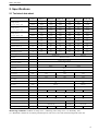
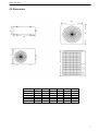
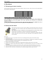
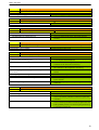
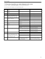
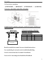
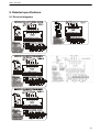
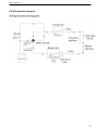
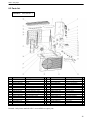
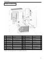
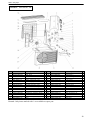
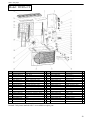
1
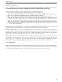
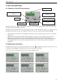
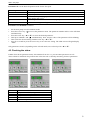
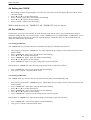
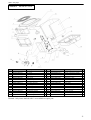
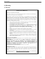
SWIMMING POOL HEAT PUMP UNITS Installation & Instruction Manual DURA+ ® - series Rev. 2.00 20.12.2010 DURA+ heat pumps Contents SWIMMING POOL HEAT PUMP UNITS _____________________________________________ 1 Contents _________________________________________________________________________ 2 1. Preface ________________________________________________________________________ 3 2. Specifications ___________________________________________________________________ 4 2.1 Technical data sheet _________________________________________________________________________ 4 2.2 Dimensions ________________________________________________________________________________ 5 3. Installation and connection ________________________________________________________ 6 3.1 Remarks __________________________________________________________________________________ 6 3.2 Location of the heat pump ____________________________________________________________________ 6 3.3 Distance from the pool _______________________________________________________________________ 7 3.4 Installation of the check-valve _________________________________________________________________ 7 3.5 Typical setup ______________________________________________________________________________ 8 3.6 Adjusting the by-pass ________________________________________________________________________ 8 4. Use and operation ______________________________________________________________ 11 4.1 Features of the LED control panel _____________________________________________________________ 11 4.2 Setting the parameters ______________________________________________________________________ 11 4.3 Checking the status ________________________________________________________________________ 13 4.4 Setting the CLOCK ________________________________________________________________________ 14 4.5 Use of timers _____________________________________________________________________________ 14 5. Protection systems ______________________________________________________________ 15 5.1 Water pressure switch ______________________________________________________________________ 15 5.2 Refrigerant gas high and low pressure protection _________________________________________________ 15 5.3 Overheating protection on the compressor ______________________________________________________ 15 5.4 Automatic defrost control ___________________________________________________________________ 15 5.5 Temperature difference between inflowing and outflowing water ____________________________________ 15 5.6 Low temperature cut-out ____________________________________________________________________ 15 5.7 Anti-frost protection during winter ____________________________________________________________ 16 6. Directions _____________________________________________________________________ 17 6.1 Swimming pool water chemistry ______________________________________________________________ 17 6.2 Setting the flow switch ______________________________________________________________________ 17 6.3 Heat pump winterizing ______________________________________________________________________ 18 6.4 Restarting the pump after winter ______________________________________________________________ 18 6.5 Check-up ________________________________________________________________________________ 18 7. Maintenance and inspection ______________________________________________________ 19 7.1 Maintenance ______________________________________________________________________________ 19 7.2 Troubleshooting guide ______________________________________________________________________ 19 7.3 Overview of possible error codes displayed on the screen __________________________________________ 22 7.4 Check list for installation ____________________________________________________________________ 23 8. Detailed specifications ___________________________________________________________ 24 8.1 Electrical diagrams _________________________________________________________________________ 24 8.2 Refrigeration diagram ______________________________________________________________________ 25 8.3 Parts list _________________________________________________________________________________ 26 9. Warranty _____________________________________________________________________ 32 9.1 Warranty _________________________________________________________________________________ 32 2 DURA+ heat pumps 1. Preface In order to provide our customers with quality, reliability and versatility, this product has been made according to strict production standards. This manual includes all necessary information about installation, start-up, winterizing and maintenance. Please read this manual carefully before opening or servicing the unit. The unit must be installed by qualified personnel. The following conditions apply for the warranty to be valid: • The heat pump can only be installed and serviced by a qualified installer. • Operation and maintenance must be carried out according to the recommendations featured in this instruction manual. • Use genuine standard spare parts only. • Make sure the heat pump is always transported or installed in the correct upright position. In case the heat pump is manipulated in any other position, severe damage can occur. Failure to comply with these recommendations will invalidate the warranty. The company will not be held responsible for damage or injury caused by improper installation or incorrect or unnecessary maintenance. The Swimming Pool Heat Pump Unit heats the swimming pool water and keeps the temperature constant. Our DURA+ heat pumps have the following characteristics: ® 1. Durability The heat pump is equipped with a PVC & Titanium heat exchanger, which can withstand prolonged exposure to swimming pool water. 2. Easy installation Before leaving our factory, all our heat pumps are thoroughly tested and made ready-to-use. Only water and power need to be connected during installation. 3. Silent operation An extremely efficient rotary/scroll compressor and a low-noise 2-speed fan guarantee silent operation of our heat pumps. 4. Advanced controlling By means of the electronic control panel, all parameters can be set and the status of all measured variables can be displayed. Remote controlling can also be achieved. 3 DURA+ heat pumps 2. Specifications 2.1 Technical data sheet Unit Heating Capacity Air: 25°C / Water: 25°C Heating capacity Air: 15°C / Water: 25°C Cooling capacity Air: 25°C / Water: 25°C Power Input Model DURA+7 DURA+10 DURA+14 DURA+19 DURA+22T DURA+30T kW 7 9,8 14,3 19,6 22,5 31 BTU/h 23900 33450 48500 66500 76700 105000 kW 6,8 9,5 13,5 18,6 21,3 29,4 BTU/h 23100 32400 46000 63500 72700 100000 kW 5,2 7,6 12,0 16,4 19,5 22,5 BTU/h 17700 26000 41000 56000 66300 76500 kW 1,2 1,71 2,46 3,44 3,9 5,2 5,8 5,7 5,8 5,7 5,8 5,9 COP at A25/W25 COP at A15/W25 5,3 5,25 5,3 5,25 5,2 5,2 Maximum volume (1) m3 30 40 60 80 95 130 Running Current A 5,22 7,43 10,7 14,96 7,6 9,7 Max Running Current A 6,5 9,3 13,4 18,7 9,7 12,6 Power Supply V/Ph/Hz 220-240/1/50 400/3/50 Controller Electronic control Condenser Titanium heat exchanger Compressor Quantity 1 Compressor type Rotary Scroll Refrigerant R410a Pressure gauge Yes High air flow M3/h 2100 2300 5000 Low air flow M3/h 1800 2000 4300 Fan quantity Fan Power Input Fan Speed 1 W 120 200 RPM 850/750 830/730 Horizontal Vertical Fan Direction Noise dB(A) 50 51 54 54 58 58 6,0 7,5 10,5 Water Connection mm Nominal Water Flow m3/h Water Pressure Drop (max) kPa Unit Net Dimensions (mm) L/W/H 905/420/650 1200/470/850 700/660/880 Unit Shipping Dimensions (mm) L/W/H 1030/440/700 1240/480/900 760/720/940 Net Weight / Shipping Weight Kg 50 3 3 4,5 10 55/60 60/65 12 77/82 117/128 102/130 110/140 Measuring conditions: Outdoor air temp: 25°C , Inflowing water temp: 25°C, rel. humidity: 65% (1) : Maximum volume for an entirely insulated pool, with cover, free from wind and exposed to the sun. 4 DURA+ heat pumps 2.2 Dimensions D A E B C F Model DURA+ 7 DURA+ 10 DURA+ 14 DURA+ 19 DURA+ 22T DURA+ 30T A(mm) 420 420 420 470 B(mm) 905 905 905 1200 C(mm) 650 650 650 850 D(mm) E(mm) F(mm) 660 660 700 700 880 880 5 DURA+ heat pumps 3. Installation and connection 3.1 Remarks The factory only provides the heat pump unit; the other parts, including a contingent by-pass, are to be provided by the user or the installer. Attention: Please take the following steps when installing the heat pump: 1. Each addition of chemicals has to be performed through the conduits located AFTER the heat pump. 2. Install a by-pass 3. Always place the heat pump on a solid base and use the supplied silent blocks in order to avoid vibrations and noise. 4. Always keep the heat pump in upright position. If the unit has been tilted, you should wait for at least 24 hours before turning it on. 3.2 Location of the heat pump The unit will perform well on any location provided three factors are present: 1. Fresh air - 2. Electricity - 3. Pool filter piping The unit may be installed virtually anywhere outdoors providing minimum distance requirements are met with respect to other objects (see diagram below). For indoor pools please consult your installer. If the unit is placed in a windy area, no problems occur with e.g. the pilot light, as opposed to what is often the case with gas heaters. ATTENTION: Do not place the unit in an enclosed area with a limited air volume where the unit's discharged air will be re-circulated or near shrubs that could block the air inlet. These locations deny the unit a continuous fresh air supply, which reduces its efficiency and may prevent adequate heat yield. See diagram below for minimum required distances. 6 DURA+ heat pumps 3.3 Distance from the pool Normally, the pool heat pump is installed within a 7.5 meter radius of the pool. The greater the distance from the pool, the greater the heat loss from the piping. Since the piping is buried for the most part, heat loss is minimal for distances of up to 30 meters (15 meters to and from the pump = 30 meters total), unless the soil is wet or the water level is high. Heat loss per 30 meters could roughly be estimated at 0.6 kW-hour (2000 BTU) for every 5 °C temperature difference between the pool water and the soil surrounding the pipe, which translates to an operation time increase of 3 to 5 %. 3.4 Installation of the check-valve Attention – When using automatic chlorine and pH dosage systems, it is of uttermost importance to protect the heat pump from high concentrations of these chemicals that could corrode the heat exchanger. Therefore, such systems should add the chemicals in the conduits located DOWNSTREAM of the heat pump and it is recommended to install a check-valve in order to prevent backflow when there is no water circulation. Damage to the heat pump caused by disregarding any of these recommendations will invalidate the warranty. 7 DURA+ heat pumps 3.5 Typical setup Note – This setup is just an example 3.6 Adjusting the by-pass F r o m P o o l T o P o o l BY -‐ PASS Valve 1 Valve 3 Valve 2 in out Heat pump The heat pump reaches maximum efficiency when temperature difference between IN and OUT is about 1 – 2 degrees Celsius (see parameters A and B, par 4.3). The temperature difference is influenced by the flow of water through the heat pump. The flow can be adjusted with By-pass valve 1. The flow increases when valve 1 is shut more and vice versa. Operating pressure of the refrigerant can be monitored on the pressure gauge of the heat pump. The pressure is infuenced by water- and ambient temperature and is automatically controlled by the heat pump. Note – The absence of a by-pass or performing an inadequate by-pass adjustment may cause the heat pump to function less well or may even damage it, which will invalidate the warranty. 8 DURA+ heat pumps 3.7 Electrical hook-up Important - Although the heat pump is electrically isolated from the rest of the unit, this only prevents the passage of electricity to or from the pool water. Grounding the unit is still required to protect yourself from short circuits inside the unit. Make for adequate ground connection. Check if the electrical mains voltage corresponds with the operating voltage of the heat pump prior to hooking up the unit. It is recommended to use a separate fuse (slow type – D-curve) as well as adequate wiring (see table below). Connect the electrical wires with the terminal block labelled ‘TO POWER SUPPLY’. Next to this connection, there is a second terminal block labelled ‘TO PUMP’, to which the filter pump (max. 5A/240V) or an electrical relay for a filtration pump can be connected. This connection makes it possible to control filter pump operation with the heat pump. See further; paragraph 4.2 (parameter 9) for the different possibilities. “TO PUMP” connection Remark – For 3 phase motors (like a compressor), switching 2 phases may cause an inversion in the rotational direction, which could damage the unit. Therefore, a protection device has been built in, which will interrupt the circuit if the connection has not been performed correctly. If, right after electrical connection has been made, the display of the pump does not illuminate, and the pump doesn’t start, 2 phase wires have to be switched. Model Voltage (volt) Fuse (A) Nominal current (A) Cable diameter (mm2) (for a max. length of 15 meters) DURA+ 7 DURA+10 DURA+14 DURA+19 DURA+ 22T DURA+ 30T 220-240 220-240 220-240 220-240 3 x 400 3 x 400 10 16 20 25 20 20 5,22 7,43 10,7 14,96 7,6 9,7 2 x 2,5 + 2,5 2*2.5 + 2.5 2*2,5 + 2.5 2*2.5 + 2.5 4 x 2,5 + 2,5 4 x 2,5 + 2,5 9 DURA+ heat pumps 3.8 First time start-up Note - In order for the unit to heat the pool (or spa), the filter pump must be running so that the water can circulate through the heat pump. Without this circulation, the heat pump will not start. When all connections have been made and checked, you should follow these steps: 1. Turn on the filter pump. Check for leaks and verify flow to and from the pool. 2. Turn on the electrical power supply to the unit, then press the ON/OFF key “ ” on the electronic control panel. The unit should start when the time delay period has lapsed (see further). 3. When the unit has been running for a couple of minutes, check if the air leaving the unit is cooler. 4. Check the performance of the flow switch as follows: with the unit running, turn the filter pump off. The unit should also switch off automatically. If not, the flow switch must be readjusted. (see further under 6.2). 5. Allow the unit and filter pump to run 24 hours a day until the desired pool water temperature is reached. When the set temperature is reached, the unit switches itself off. The unit will now automatically restart (as long as your filter pump is running) when the temperature of the pool water experiences a drop of more than 1 °C below the set temperature. Depending on the starting temperature of the pool water and the air temperature, it can take several days for the water to reach the desired temperature. Covering the pool can drastically reduce this period. Water pressure switch – the unit is equipped with a pressure switch that is switched on when enough water pressure is detected in the unit and that is switched off when the water pressure becomes too low (e.g. when the filter pump is switched off). If the pool water level is located more than one meter above or below the heat pump, your installer may need to adjust this pressure switch (see further under 6.2). Time delay – the unit is equipped with a built-in 3-minute start delay included to protect the compressor and electrical contacts. After this time delay, the unit will automatically be restarted. Even a brief interruption of the power supply will activate the start delay and prevent the unit from starting immediately. Additional interruptions of the power supply during the delay period will have no effect on the 3-minute countdown. 3.9 Condensation When the swimming pool water is being heated by the heat pump, the incoming air is cooled down quite a bit, which can cause condensation on the fins of the evaporator. Condensed volumes can attain several litres per hour under high atmospheric humidity. Sometimes, this is wrongfully interpreted as a water leak. 10 DURA+ heat pumps 4. Use and operation 4.1 Features of the LED control panel LED screen Press “▲”or“▼” to modify settings Press “MODE” to set the operating mode On/Off Set start time Access to parameters Set stop time Press “CLOCK” to set the time With the “On/Off” key “ “, the heat pump is turned on or turned off (stand-by status). If the LED next to this key lights up, the heat pump is turned ON. Setting the desired temperature of the swimming pool water is achieved with the arrow keys, regardless if the heat pump is turned ON or OFF. You simply press the arrow keys to set the desired temperature directly. • • • When the unit is turned ON and is running, the temperature of the swimming pool water can be read off the LED screen. When the unit is turned ON and the desired temperature is reached, “OFF” appears on the LED screen. When the unit is turned OFF, “OFF” is always displayed on the LED screen; the heat pump goes on monitoring all parameters of the system and all protection systems remain active. The heat pump is thus in STAND-BY mode. We will continue using this expression if we wish to indicate that the heat pump is turned OFF. 4.2 Setting the parameters Parameters can always be checked by pressing the service key “ ”, regardless if the pump is turned ON or is in STAND-BY mode. Only in STAND-BY mode can the parameters be modified. This is an overview of the different parameters and their standard values. 11 DURA+ heat pumps The first number on the LED screen stands for the number of the parameter and the second one for its value. Parameter 0 1 2 3 4 5 6 7 8 9 10 11 Description Desired temperature in cooling mode (8 ⇒ 28°C) Desired temperature in heating mode (7 ⇒ 40°C) Operation time of the compressor before defrosting mode starts (30 ⇒ 90 minutes) Temperature of evaporator at which defrosting starts (-30 ⇒ 0°C) Temperature of evaporator at which defrosting stops (2 ⇒ 30°C) Maximum duration of defrosting procedure (0 ⇒ 12 min) Number of compressors in the system (always equals 1 for DURA+ ) Memory function for automatic start-up (0 for ‘no’ and 1 for ‘yes’) Operating mode (see table below) Filter pump control (0 for ‘on’ and 1 for ‘automatic’) Fan mode (see table below) Fan control type (0 for triac control and 1 for voltage control) ® Standard 20°C 27°C 45 min -7°C 13°C 8 min 1 1 3 0 2 1 Parameters 2 up to and including 5 are the settings for the automatic defrosting mode. They have been set from the factory for optimal operation and very rarely need to be adjusted by a specialized technician, that is, only if conditions demand it. Parameter 7 indicates if the heat pump should or shouldn’t start automatically after an interruption of the power supply. Parameter 8 is for adjusting the possible operating modes of the heat pump. Value for parameter 8 1 3 Possible modes Cooling or heating (manual/auto) Heating only Can be selected with “Mode” key Yes Parameter 9 is for determining how the filter pump should be controlled. If you want to have it controlled by the heat pump, you have to connect the electrical wires of this pump, through a separate relay, to the terminal block labelled ‘TO PUMP’ that is located next to the one labelled ‘TO POWER SUPPLY’. Value for parameter 9 0 1 Control The filter pump runs as long as the heat pump is turned ON The filter pump starts running 3 minutes before the heat pump is actually heating and stops 30 seconds after the heat pump has stopped 12 DURA+ heat pumps Parameter 10 sets the desired operation mode for the fan speed. Value for parameter 10 0 1 2 3 4 Fan control Low fan speed High fan speed Automatic fan speed (high speed when air temperature is below 10°C, low speed when higher than 15°C) Low fan speed between 9PM and 8AM, high speed at other time Automatic running according to a combination of value 2 and 3 Parameters are modified as follows: • • • • • • Set the heat pump in its STAND-BY mode. Press the service key “ ”to access the parameter menu. The parameter number and its value will blink simultaneously. Press the arrow key “▲”or“▼” to select the desired parameter. Then press “MODE” and “ ” simultaneously. Now, only the value of the parameter will be blinking. Then select the desired setting with the arrow key “▲”or“▼”. Stop for 5 seconds or press the service key to save the new setting. The LED screen will again display “OFF”. Only parameters 0 and 1 (depending on the selected mode) are set directly with “▲”or“▼” 4.3 Checking the status Further down in the parameter menu, after numbers from 0 to 11, you encounter parameters A to E. These cannot be modified. They indicate the values the unit is currently measuring for these parameters. Parameter A B C D E Measured value Temperature of in flowing water Temperature of out flowing water Temperature of evaporator Not used Ambient temperature 13 DURA+ heat pumps 4.4 Setting the CLOCK • • • • • Start setting the clock by pressing the “CLOCK” key. The LED screen will display the time and the hours will start to blink. Press “▲”or“▼” to set the desired hour. Press “CLOCK” again. Now, the minutes start blinking. Press “▲”or“▼” again to set the minutes. Press “CLOCK” again to save the settings. While setting the clock, the “TIMER ON” and “TIMER OFF” keys are inactive. 4.5 Use of timers Timers allow you to set a time window in which the heat pump will be active. If you want the heat pump to work only during the day, you can for instance set the “TIMER ON” key to 08:00 and the “TIMER OFF” key to 20:00. Setting the time can only be achieved when the pump is turned ON. When it is in STAND-BY mode, timers are automatically deactivated. 4.5.1 Setting TIMER ON The “TIMER ON” key activates the time at which the heat pump is automatically turned on. • • • • • • Start setup by pressing the “TIMER ON” key. This displays the previously set time on the LED screen and makes it blink. Press “TIMER ON” again. Now, only the hours start blinking. Press “▲”or“▼” to set the desired hour. Press “TIMER ON” again. Now, the minutes start blinking. Press “▲”or“▼” again to set the minutes. Press “TIMER ON” again to save the setting and to activate start time. Deactivation of “TIMER ON” when the heat pump is turned ON is achieved as follows: • • Press “TIMER ON”. The set time appears and starts blinking. Now, press “CLOCK” to deactivate the timer. 4.5.2 Setting TIMER OFF The “TIMER OFF” key activates the time at which the heat pump will automatically stop. • • • • • • Start setup by pressing the “TIMER OFF” key. This displays the previously set time on the LED screen and makes it blink. Press “TIMER OFF” again. Now, only the hours start blinking. Press “▲”or“▼” to set the desired hour. Press “TIMER OFF” again. Now, the minutes start blinking. Press “▲”or“▼” again to set the minutes. Press “TIMER OFF” again to save the setting and to activate stop time. Deactivation of “TIMER OFF” when the heat pump is turned ON is achieved as follows: • • Press “TIMER OFF”. The set time appears and starts blinking. Now, press “CLOCK” to deactivate the timer. 14 DURA+ heat pumps 5. Protection systems DURA+ heat pumps are equipped with the following standard protection systems: ® 5.1 Water pressure switch Thanks to this pressure switch, the heat pump will not work when the filter pump is not working (and the water is not circulating). This system prevents the heat pump from heating only the water present in the heat pump itself. The protection also stops the heat pump if water circulation is cut off or stopped. 5.2 Refrigerant gas high and low pressure protection The high pressure protection makes sure the heat pump is not damaged in case of overpressurisation of the gas. The low pressure protection emits a signal when refrigerant is escaping from the conduits and the unit cannot be kept running. 5.3 Overheating protection on the compressor This protection protects the compressor from overheating. 5.4 Automatic defrost control When the air is very humid and cold, ice can form on the evaporator. In that event, a thin layer of ice appears that will grow increasingly bigger as long as the heat pump is running. When the temperature of the evaporator has become too low, automatic defrost control will be activated, which will reverse the heat pump cycle so that hot refrigerant gas is sent through the evaporator during a brief period of time to defrost it. 5.5 Temperature difference between inflowing and outflowing water During normal operation of the heat pump, the temperature difference between inflowing and outflowing water will approximate 1 to 2 °C. In the event that the pressure switch does not work and that the water stops circulating, the temperature probe monitoring the outflowing water will always detect a rise in temperature. As soon as the temperature difference between inflowing and outflowing water exceeds 13 °C, the heat pump will be automatically turned off. 5.6 Low temperature cut-out If, during cooling, the temperature of the outflowing water reaches 5 °C or drops below this temperature, the heat pump will turn itself off until the water temperature reaches or exceeds 7 °C again. 15 DURA+ heat pumps 5.7 Anti-frost protection during winter This protection can only be activated if the heat pump is in STAND-BY mode. 5.7.1 First anti-frost protection If the filter pump is controlled by the heat pump (regardless of the value for parameter 9) and when the water temperature lies between 2 and 4 °C and the air temperature is lower than 0 °C, the filter pump will be automatically turned on to prevent the water from freezing in the piping. This protection is deactivated when the temperature rises again. 5.7.2 Second anti-frost protection If the water temperature drops even more, that is, below 2 °C (during long frost periods), the heat pump will also start running to heat the water until its temperature approximates 3 °C. When this temperature is reached, the heat pump will stop, but anti-frost protection will remain active until conditions change. 16 DURA+ heat pumps 6. Directions 6.1 Swimming pool water chemistry Special attention should be paid to the chemical balance of the pool water. The pool water values should always stay within the following limits: pH Free chlorine (mg/l) TAC (mg/l) Salt (g/l) Min. 7.0 0.5 80 Max. 7.8 1.2 150 8 Important: failure to comply with these limits will invalidate the warranty. Note: exceeding one or several limits can damage the heat pump beyond repair. Always install water treatment equipment past the heat pump’s water outlet, especially if the chemicals are automatically added to the water. A check-valve should also be installed between the outlet of the heat pump and this equipment in order to prevent products from flowing back into the heat pump if the filter pump stops. 6.2 Setting the flow switch The water flow switch is set to 0.14 bar by default. As from this water pressure value, the heat pump will be able to function. This is the minimum required water pressure for most installations. This setting may only be modified if the heat pump does not start running despite sufficient water circulation or if it does not stop when the filter pump stops. Always make sure that the water filter is clean before adjusting the settings of the flow switch: a dirty filter will lower the water flow and hamper correct adjustment of the flow switch settings. Directions: 1. Check that all valves are opened so that water can run through the heat pump. Start the filter pump. 2. Start the heat pump. 3. If the heat pump does not start after the time delay, there might not be enough water circulation. Investigate and correct contingent circulation problems prior to adjusting the flow switch. 4. Remove the heat pump’s access panel. 5. Turn the screw on the flow switch slowly in anticlockwise direction, until you hear a soft click. 6. Repeat step 5 until the heat pump starts running. It is possible that the screw has to be turned several revolutions. 7. Once the heat pump is running, stop the filter pump. The heat pump should immediately turn itself off. 8. If the heat pump does not turn itself off, the screw should be turned clockwise until the heat pump stops. 9. Check once more if the flow switch functions correctly by turning the filter pump on and off. 17 DURA+ heat pumps 6.3 Heat pump winterizing Important: failure to take the necessary precautions for winterizing can damage the heat pump, which will invalidate the warranty. The heat pump, filter pump, filter and conduits must be protected in areas where the temperature can drop below the freezing point. Evacuate all water from the heat pump as follows: 1. interrupt the electrical power supply to the heat pump 2. close the water supply to the heat pump: completely close valves 2 and 3 of the by-pass 3. disconnect the water inlet and outlet coupler fittings of the heat pump and let the water drain out of the unit 4. loosely reattach water inlet and outlet coupler fittings to the heat pump in order to prevent dirt from getting into the conduits. Note: these precautions should not be taken if you choose to use the built-in anti-frost protection. 6.4 Restarting the pump after winter If you purged your heat pump for winterizing, you should undertake the following steps to restart it in spring: 1. check first if there is no dirt in the conduits and if there are no structural problems 2. check if the water inlet and outlet coupler fittings are adequately fastened to the heat pump 3. start the filter pump to start the water flow to the heat pump. Set the by-pass again. 4. reconnect the electrical power supply to the heat pump and turn it ON. 6.5 Check-up DURA+ heat pumps have been developed and built to last, that is, if they have been installed correctly and can run under normal conditions. Regular check-ups are important if you want your heat pump to function safely and efficiently for years on end. The following directions can help you achieve optimal results: 1. make for easy access to the service panel 2. keep the area surrounding the heat pump free of contingent organic waste 3. prune the vegetation near the heat pump so that there is enough free space around the pump 4. remove contingent water sprinklers from the vicinity of the heat pump. They can damage the heat pump. 5. prevent rain from directly running off a roof onto the heat pump. Install proper drainage. 6. do not use the heat pump if it has been flooded. Immediately contact a qualified technician to inspect the heat pump and repair it if should prove necessary. ® Condensation can occur when the heat pump is running. This condensation can flow away through an opening in the base pan of the unit. The amount of condensation water will increase when atmospheric humidity is high. Remove any dirt that could possibly hamper the evacuation of condensation. 10 to 20 litres of condensation water can be produced while the unit is running. If more condensation is produced, stop the heat pump and wait for one hour before checking for leaks in the conduits. NOTE: A quick way to verify that the water running through the condensation drain is indeed condensation, is to shut off the unit and keep the pool pump running. If the water stops running out of the condensation drain, it is condensation. AN EVEN QUICKER WAY is to TEST THE DRAIN WATER FOR CHLORINE. If no chlorine is detected, the drain water is a result of condensation. Also take care to leave air inlet and exhaust passages free. Prevent exhaust air from immediately re-entering the unit through the inlet. 18 DURA+ heat pumps 7. Maintenance and inspection 7.1 Maintenance • • • • • • Check the water inlet and drainage often. The water and air inflow into the system should be sufficient so that its performance and reliability does not get compromised. You should clean the pool filter regularly to avoid damage to the unit caused by clogging of the filter. The area around the unit should be spacious and well ventilated. Clean the sides of the heat pump regularly to maintain good heat exchange and to save energy. Check if all processes in the unit are operational and pay special attention to the operation pressure of the refrigerant system. Check the power supply and cable connections regularly. Should the unit begin to function abnormally or should you notice a smell from an electrical component, arrange for timely repair or replacement. Winterizing : make sure to purge all the water from the heat pump and other systems in order to prevent frost damage. You should also purge the water if the unit will not work for an extended period of time. You should check all parts of the unit thoroughly and completely fill the system with water before turning it on again afterwards. 7.2 Troubleshooting guide Improper installation may result in an electrical discharge that could lead to death of – or serious injury to – pool users, installers or others due to electrical shock and may also cause damage to property. DO NOT attempt to modify the internal configuration of the heat pump. 1. Keep your hands and hair clear of the fan blades to avoid injury. 2. If you are not familiar with your pool filtering system and heat pump: a. Do not attempt to adjust or service without consulting your dealer or your professional pool or air conditioning contractor. b. Read the entire installation and user manual before attempting to use, service or adjust the unit. c. Start the heat pump at least 24 hours after its installation in order to prevent damage to the compressor. Nota: Switch off the power prior to maintenance or repairs. Important remark: if a malfunction cannot be resolved immediately, your installer can contact our customer service. To be able to help you, we will need the serial number (format: 5xxRWxxxxxxxxx) of your heat pump. In order to analyse the problem itself, we will need to know the message (error code) that is displayed on the LED screen, as well as the values for the settings (parameters 0 to 11) and for the status of the heat pump (parameters A to E) just before the failure or, if this is impossible, just after it. Please keep this information at hand when calling our customer service. This information is also indispensable if you need to return a heat pump. Returning the unit should occur according to our RMA procedure guidelines. On the following pages, you will find an overview of the different types of failure problems that can occur, along with directions to solve them. 19 DURA+ heat pumps Problem: Observation: the heat pump doesn’t work the screen does not light up and the fan/compressor doesn’t make a sound Possible cause Solution No electrical power supply Check power supply (wiring, fuses, ...) Problem: Observation: the heat pump doesn’t work the screen displays “OFF” and the LED next to “ ” is not lit Possible cause The pump is in stand-by mode Turn on the pump Solution Problem: Observation: 1. 2. the heat pump doesn’t work the screen displays “OFF” and the LED next to “ ” is lit Possible cause Solution The set temperature has been reached 1. No action required; all is well The heat pump isn’t functioning yet 2. Wait until the start time delay period has lapsed (3 minutes) Problem: Observation: the heat pump works but doesn’t heat the compressor is running but the fan isn’t and the “HEATING/DEFROST” LED is blinking Possible cause Solution The defrosting cycle is running No action required; all is well Problem: Observation: 1. 2. 3. 4. 5. 6. 7. 8. the heat pump works normally but there is no or insufficient heating the screen displays the temperature but no error codes Possible cause Solution Insufficient capacity of the heat pump in proportion to 1. Install a larger sized model or an extra heat pump. the size of the swimming pool Cover the pool to limit heat loss The compressor works but the fan doesn’t 2. Check the electrical wiring of the fan. Replace the condenser or the fan motor if necessary. The fan works but the compressor doesn’t 3. Check the electrical wiring of the compressor. Replace the condenser or the compressor if necessary. The heat pump has not been placed on an optimal 4. Make for sufficient air circulation (see manual for location details) Faulty temperature setting 5. Set the correct temperature By-pass not adjusted 6. Have the by-pass readjusted by the installer Massive ice formation on the evaporator 7. Have the settings for automatic defrost control checked by the installer Not enough refrigerant 8. Have the heat pump checked by a refrigeration technician Problem: Observation: the heat pump works normally but the water is cooling down instead of heating up the screen displays the temperature but no error codes Possible cause Solution 1. The wrong mode has been selected 1. Verify the parameters, select the correct mode 2. The controller is out of order 2. Check the voltage in the electrical wiring to the 4-way valve. If no electric potential is measured, replace the controller 3. The 4-way valve is out of order 3. Check the voltage in the electrical wiring to the 4-way valve. If electric potential is measured, replace the coil. If the problem persists, have the heat pump checked by a refrigeration technician 20 DURA+ heat pumps Problem: Observation: the heat pump works but stops after a short while the screen displays “OFF” Possible cause Solution 1. Wrong setting of parameters 1. Check the settings of the parameters and modify if necessary Problem: Observation: the heat pump doesn’t stop the screen displays the temperature but no error codes Possible cause Solution 1. Wrong setting of parameters 1. Check the set parameters and adjust them if necessary (settings just above the capacity of the heat pump) 2. Pressure switch out of order 2. Check operation of the pressure switch by turning off the filter pump and restarting it. If the heat pump doesn’t react to this, the pressure switch must be adjusted or replaced. 3. Electrical failure 3. Contact your installer Problem: Observation: water leak there’s an amount of water under the heat pump Possible cause Solution 1. Condensation due to atmospheric humidity 1. No action required 2. Water leak 2. Try to localize the leak and check for the presence of chlorine in the water. If that is the case, the heat pump must be temporarily replaced during repair. Problem: Observation: 1. 2. 3. 4. 5. abnormal amount of ice formed on the evaporator the evaporator is for the most part covered in ice Possible cause Solution Insufficient air inflow 1. Check the location of the heat pump and remove any dirt that could be present on the evaporator High water temperature 2. If the pool water is already quite hot (warmer than 29 °C), the probability of ice formation increases. Lowering the set temperature is a possible option. Incorrect setting of automatic defrost control 3. Check the settings of the defrosting function together with your installer The 4-way valve is out of order 4. Check the voltage in the electrical wiring to the 4way valve. If electric potential is measured, replace the coil. If the problem persists, have the heat pump checked by a refrigeration technician. Not enough refrigerant 5. Have the heat pump checked by a refrigeration technician. 21 DURA+ heat pumps 7.3 Overview of possible error codes displayed on the screen Go back to chapter 5 “Protection systems” for more detailed information. The heat pump screen displays one of the following codes: Display PP1 PP2 PP3 PP5 PP6 PP7 Problem “WATER IN” sensor out of order “WATER OUT” sensor out of order “PIPE” sensor out of order “AIR” sensor out of order Temperature difference between “WATER IN” and “WATER OUT” is too large Water temperature too low during cool-down PP7 First anti-frost protection active PP7 HP Second anti-frost protection active High pressure protection LP Low pressure protection Cause Sensor open or short-circuited Solution Check or replace the sensor Sensor open or short-circuited Check or replace the sensor Sensor open or short-circuited Sensor open or short-circuited Insufficient water flow Check or replace the sensor Check or replace the sensor Check the water flow Pressure switch out of order Replace the pressure switch Insufficient water flow Check the water flow Sensor “WATER OUT” displays an incorrect message Low temperatures for water and air Low temperatures for water and air Insufficient water flow Pressure switch out of order Too much refrigerant gas present Not enough refrigerant gas Check or replace the sensor Insufficient water flow EE5 The temperature difference between “WATER IN” and “WATER OUT” has been too large 3 times in a row Communication failure EE8 No action required Insufficient water flow Pressure switch out of order Insufficient water flow Check the water flow Replace the pressure switch Have the heat pump checked by a refrigeration technician Have the heat pump checked by a refrigeration technician Have the heat pump checked by a refrigeration technician Check the water flow Replace the pressure switch Check the water flow Pressure switch out of order Replace the pressure switch No communication between the digital display and the system controller Check the connection between the screen and the controller. Replace screen and/or controller. Leak in the cooling conduits FLO No action required 22 DURA+ heat pumps 7.4 Check list for installation ATTENTION / OPGELET / ATTENTION / ACHTUNG 1. Free area / vrije ruimte / espace libre / freier platz 2. Install a by-pass / installeer een by-pass / installez un by-pass / installieren sie eine Überbrückung BYPASS Valve 1 Valve 3 DURA+7 DURA+10 DURA+14 DURA+19 DURA+22T DURA+30T Valve 2 out 3. Electrical connection / elektrische aansluiting / raccordement électrique / elektrischer Anschluss 220-240V 220-240V 220-240V 220-240V 3x 380V 3x 380V 10A 16A 20A 25A 20A 20A 2*2,5 + 2,5mm2 2*2,5 + 2,5 mm2 2*2,5 + 2,5 mm2 2*4 + 4 mm2 4*2,5 + 2,5 mm2 4*2,5 + 2,5 mm2 in Heat pump Read the installation manual for more detailed instructions Lees aandachtig de instructies in de installatiehandleiding Lisez les instructions dans le manuel d’installation Lesen sie die Anweisungen im Installation Handbuch 23 DURA+ heat pumps 8. Detailed specifications 8.1 Electrical diagrams RK1 1 K1 BLU HEATER Contactor K1 RED ORG BLU RED LP HP Rk4 RK1 10 GND REMARKS: 1.C1:CAP. OF COMPRESSOR 2.C2:CAP. OF FAN MOTOR 12V 3.CM:COMPRESSOR; 4. EXT.: AMBIENT TEMPERATURE 230V 5 6 7 8 15 4 9 12 13 14 10 SENSOR; GND GND GND GND GND GND 5. FM: FAN MOTOR; 6.HP:HIGH PRESSURE PROTECT SWITCH; INWT OUWT PIPE EVAP EXT FLW HP LP KYIN 7. INWT: WATER INLET SENSOR; L N Wire controller 8.K1:RELAY OF COMPRESSOR; o o o o o b b b b B B O O 9.K4:RELAY OF WATER PUMP; 10.LP:LOW PRESSURE PROTECT SWITCH; t` t` t` t` 11.OUWT:WATER OUTLET SENSOR; Remote ON/OFF 12.PIPE.:CONDENSING TEMPERATURE Inlet water Pipe Ambient Low High SENSOR; temperature temperature temperature pressure pressure 13.RK1:RELAY COIL OF COMPRESSOR; Outlet water Flow protect protect temperature switch 14.RK4:RELAY COIL OF WATER PUMP; 15.WATER:WATER FLOW SWITCH. 9 FLW 12 13 14 15 BLK BLK BLK BLK 8 MDIN 10 EXT. 9 7 2 GND 8 6 1 KYIN 7 PIPE 6 5 EVAP. 5 4 3 NET 2 INWT 12V 12V 1 Y/G BRN BLU BLK BLK BLK BLK BLK BLK BLK 4 12V TO POWER SUPPLY TO PUMP 220~230VAC 220~230VAC 3 Y/G BRN BLU BLK BLK BLK BLK BLK BLK BLK N TO PUMP REMARKS: 1.C1:CAP. OF COMPRESSOR 2.C2:CAP. OF FAN MOTOR 3.CM:COMPRESSOR; 4.EP:EXHAUST PROTECT 5. EXT.: AMBIENT TEMPERATURE SENSOR; 6. FM: FAN MOTOR; 7.HP:HIGH PRESSURE PROTECT SWITCH; 8. INWT: WATER INLET SENSOR; 9.KM1:CONTACTOR OF COMPRESSOR; 10.K4:RELAY OF WATER PUMP; 11.LP:LOW PRESSURE PROTECT SWITCH; 12.OUWT:WATER OUTLET SENSOR; 13.PIPE.:CONDENSING TEMPERATURE SENSOR; 14.RK1:CONTACTOR COIL OF COMPRESSOR; 15.RK4:RELAY COIL OF WATER PUMP; 16.WATER:WATER FLOW SWITCH. GND LP HP FLW KYIN MDIN EXT. GND PIPE EVAP. OUWT NET +12V INWT 2 GND 1 ~12V N ~12V L L +12V N Y/G 12V L TO POWER SUPPLY PC2000 GND PC2000 RED BLU Y/G RED ~12V Y/G L ~12V AC-L FAN-L COMP PUMP FAN-H 4VAL K4 N K1 RED OUWT L N K3 RED RED RED L STARTING RELAY K4 BLU AC-L K4 BLU L K3 RED K DURA+19 N 1 BLU FAN-L BLU BLK Low speed PUMP C1 N STARTING CAP. 1 5 N ORG COMP WHT Rk4 R S K1 N High speed CM 2 FM Y/G C1 WHT BLK BLU WHT 4VAL C BLK RED R S FAN-H Y/G RED DURA+7 Low speed FM Y/G C 4-way valve BLU C2 COMP Y/G WHT BLK RELAY K4 C2 High speed SWIMMING POOL HEATER WIRING DIAGRAM 12 13 14 15 BLK BLK BLK BLK 12V 4 9 230V L N INWT Wire controller o t` GND 5 6 OUWT O t` o 7 8 15 GND PIPE b t` Inlet water Pipe temperature temperature Outlet water temperature EVAP B GND EXT b 12 13 FLW o O o GND GND 14 10 HP LP b B GND KYIN o b MDIN O o t` Ambient temperature Remote ON/OFF High Low pressure pressure protect protect Flow switch Exhaust Protect MDIN o O SWIMMING POOL HEATER WIRING DIAGRAM C2 WHT BLK BLU WHT C1 BLU RK1 S R N Rk4 BLK RED K4 BLU K1 BLU L ORG RED FAN-L AC-L 1 4VAL K3 RED FAN-H K1 N High speed C CM DURA+ 10 Low speed FM Y/G Y/G RED PC2000 RED BLU Y/G 10 LP 9 GND 8 HP KYIN 7 FLW GND 6 Y/G BRN BLU BLK BLK BLK BLK BLK BLK BLK MDIN EXT. 5 PIPE 4 EVAP. NET INWT 2 OUWT GND +12V 1 3 12V 2 12V 1 ~12V N ~12V L PUMP N COMP K4 L TO POWER SUPPLY TO PUMP 220~230VAC 220~230VAC REMARKS: 1.C1:CAP. OF COMPRESSOR 2.C2:CAP. OF FAN MOTOR 3.CM:COMPRESSOR; 12 13 14 15 BLK BLK BLK BLK 12V 4. EXT.: AMBIENT TEMPERATURE 230V 5 6 7 8 15 4 9 12 13 14 10 SENSOR; GND GND GND GND GND GND 5. FM: FAN MOTOR; 6.HP:HIGH PRESSURE PROTECT SWITCH; INWT OUWT PIPE EVAP EXT FLW HP LP KYIN 7. INWT: WATER INLET SENSOR; L N Wire controller 8.K1:RELAY OF COMPRESSOR; o o o o o b b b b B B O O 9.K4:RELAY OF WATER PUMP; 10.LP:LOW PRESSURE PROTECT SWITCH; t` t` t` t` 11.OUWT:WATER OUTLET SENSOR; Remote ON/OFF 12.PIPE.:CONDENSING TEMPERATURE Inlet water Pipe Ambient Low High SENSOR; temperature temperature temperature pressure pressure 13.RK1:RELAY COIL OF COMPRESSOR; Outlet water Flow protect protect temperature switch 14.RK4:RELAY COIL OF WATER PUMP; 15.WATER:WATER FLOW SWITCH. MDIN O o SWIMMING POOL HEATER WIRING DIAGRAM C2 WHT BLK BLU Y/G S N R WHT C1 BLU N RK1 BLK RED K4 BLU K1 BLU L ORG RED FAN-L AC-L 1 4VAL K3 RED FAN-H K1 DURA+14 Low speed FM Rk4 C CM High speed Y/G RED PC2000 RED BLU Y/G LP 10 HP 9 GND 8 FLW KYIN 7 MDIN 6 EXT. 5 GND 4 PIPE 3 EVAP. NET 2 INWT 1 OUWT 12V GND 2 +12V 1 ~12V N ~12V L PUMP N COMP K4 L TO POWER SUPPLY TO PUMP 220~230VAC 220~230VAC 12V 12 13 14 15 Y/G BRN BLU BLK BLK BLK BLK BLK BLK BLK BLK BLK BLK BLK REMARKS: 1.C1:CAP. OF COMPRESSOR 2.C2:CAP. OF FAN MOTOR 12V 3.CM:COMPRESSOR; 4. EXT.: AMBIENT TEMPERATURE 230V 5 6 7 8 15 4 9 12 13 14 10 SENSOR; GND GND GND GND GND GND 5. FM: FAN MOTOR; 6.HP:HIGH PRESSURE PROTECT SWITCH; INWT OUWT PIPE EVAP EXT FLW HP LP KYIN 7. INWT: WATER INLET SENSOR; L N Wire controller 8.K1:RELAY OF COMPRESSOR; o o o o o b b b b B B O O 9.K4:RELAY OF WATER PUMP; 10.LP:LOW PRESSURE PROTECT SWITCH; t` t` t` t` 11.OUWT:WATER OUTLET SENSOR; Remote ON/OFF 12.PIPE.:CONDENSING TEMPERATURE Inlet water Pipe Ambient Low High SENSOR; temperature temperature temperature pressure pressure 13.RK1:RELAY COIL OF COMPRESSOR; Outlet water Flow protect protect temperature switch 14.RK4:RELAY COIL OF WATER PUMP; 15.WATER:WATER FLOW SWITCH. MDIN O o 24 DURA+ heat pumps 8.2 Refrigeration diagram 25 DURA+ heat pumps 8.3 Parts list Model: DURA+7 No. Code 1 2 3 4 5 6 7 8 9 10 11 12 13 14 15 16 HOUS-DURA-008 HOUS-DURA-002 HOUS-DURA-006 DISP-DURA-005 DISP-DURA-012 METR-DURA-002 SWIT-DURA-006 EXPV-DURA-001 EXCH-DURA-008 WCON-DURA-010 CONT-DURA-005 COMP-DURA-009 CAPA-BOIL-001 ELEC-DURA-001 CAPA-DURA-002 ELEC-DURA-001 Description Electric box cover Right panel Handle Display Display waterproof cover Pressure gauge Water pressure switch Thermal expansion valve Titanium Heat exchanger Pump connection female Main controller board Compressor Compressor capacitor (35uF) Relay Fan motor capacitor (3uF) Relay No. Code * * * * * * * * * * * 17 18 19 20 21 22 23 24 25 26 27 28 29 30 31 32 ELEC-DURA-008 ELEC-DURA-007 ELEC-DURA-009 HOUS-DURA-007 HOUS-DURA-001 HOUS-DURA-009 HOUS-DURA-003 HOUS-DURA-004 FANS-DURA-003 FANM-DURA-007 HOUS-DURA-010 4WAY-DURA-005 HOUS-DURA-011 EVAP-DURA-001 HOUS-DURA-012 HOUS-DURA-005 Description 2-point wiring block Transformer 5-point wiring block Electric box Front panel Fan grill Middle separate panel Bottom panel Fan blade Fan motor Fan motor bracket 4-Way valve Back protection net Evaporator Support board Top cover * * * * Remark: Only items marked with * are available as spare part. 26 DURA+ heat pumps Model: DURA+10 No. Code 1 2 3 4 5 6 7 8 9 10 11 12 13 14 15 16 HOUS-DURA-008 HOUS-DURA-002 HOUS-DURA-006 DISP-DURA-005 DISP-DURA-012 METR-DURA-002 SWIT-DURA-006 EXPV-DURA-002 EXCH-DURA-009 WCON-DURA-010 CONT-DURA-005 COMP-DURA-010 CAPA-DURA-006 ELEC-DURA-001 CAPA-DURA-002 ELEC-DURA-001 Description Electric box cover Right panel Handle Display Display waterproof cover Pressure gauge Water pressure switch Thermal expansion valve Titanium Heat exchanger Pump connection female Main controller board Compressor Compressor capacitor (50uF) Relay Fan motor capacitor (3uF) Relay No. Code * * * * * * * * * * * 17 18 19 20 21 22 23 24 25 26 27 28 29 30 31 32 ELEC-DURA-008 ELEC-DURA-007 ELEC-DURA-009 HOUS-DURA-007 HOUS-DURA-001 HOUS-DURA-009 HOUS-DURA-003 HOUS-DURA-004 FANS-DURA-003 FANM-DURA-007 HOUS-DURA-010 4WAY-DURA-005 HOUS-DURA-011 EVAP-DURA-002 HOUS-DURA-012 HOUS-DURA-005 Description 2-point wiring block Transformer 5-point wiring block Electric box Front panel Fan grill Middle separate panel Bottom panel Fan blade Fan motor Fan motor bracket 4-Way valve Back protection net Evaporator Support board Top cover * * * * Remark: Only items marked with * are available as spare part. 27 DURA+ heat pumps Model: DURA+14 No. Code 1 2 3 4 5 6 7 8 9 10 11 12 13 14 15 16 HOUS-DURA-008 HOUS-DURA-002 HOUS-DURA-006 DISP-DURA-005 DISP-DURA-012 METR-DURA-002 SWIT-DURA-006 EXPV-DURA-003 EXCH-DURA-010 WCON-DURA-010 CONT-DURA-005 COMP-DURA-011 CAPA-DURA-008 ELEC-DURA-001 CAPA-DURA-002 ELEC-DURA-010 Description Electric box cover Right panel Handle Display Display waterproof cover Pressure gauge Water pressure switch Thermal expansion valve Titanium Heat exchanger Pump connection female Main controller board Compressor Compressor capacitor (60uF) Relay Fan motor capacitor (3uF) Relay No. Code * * * * * * * * * * * 17 18 19 20 21 22 23 24 25 26 27 28 29 30 31 32 ELEC-DURA-008 ELEC-DURA-007 ELEC-DURA-009 HOUS-DURA-007 HOUS-DURA-001 HOUS-DURA-009 HOUS-DURA-003 HOUS-DURA-004 FANS-DURA-003 FANM-DURA-007 HOUS-DURA-010 4WAY-DURA-006 HOUS-DURA-011 EVAP-DURA-002 HOUS-DURA-012 HOUS-DURA-005 Description 2-point wiring block Transformer 5-point wiring block Electric box Front panel Fan grill Middle separate panel Bottom panel Fan blade Fan motor Fan motor bracket 4-Way valve Back protection net Evaporator Support board Top cover * * * * Remark: Only items marked with * are available as spare part. 28 DURA+ heat pumps Model: DURA+19 No. Code 1 2 3 4 5 6 7 8 9 10 11 12 13 14 15 16 17 18 HOUS-DURA-019 HOUS-DURA-014 HOUS-DURA-006 DISP-DURA-005 DISP-DURA-012 METR-DURA-002 SWIT-DURA-006 EXPV-DURA-004 EXCH-DURA-011 WCON-DURA-010 CONT-DURA-005 COMP-DURA-012 CAPA-DURA-009 CAPA-DURA-008 ELEC-DURA-011 ELEC-DURA-001 CAPA-DURA-004 ELEC-DURA-012 Description Electric box cover Right panel Handle Display Display waterproof cover Pressure gauge Water pressure switch Thermal expansion valve Titanium Heat exchanger Pump connection female Main controller board Compressor Compressor capacitor (98uF) Compressor capacitor (60uF) Contactor Relay Fan motor capacitor (4uF) Startup relay No. Code * * * * * * * * * * * 19 20 21 22 23 24 25 26 27 28 29 30 31 32 33 34 35 ELEC-DURA-008 ELEC-DURA-007 ELEC-DURA-013 ELEC-DURA-014 HOUS-DURA-018 HOUS-DURA-013 HOUS-DURA-020 HOUS-DURA-015 HOUS-DURA-016 FANS-DURA-009 FANM-DURA-009 HOUS-DURA-021 4WAY-DURA-004 HOUS-DURA-022 EVAP-DURA-003 HOUS-DURA-023 HOUS-DURA-017 Description 2-point wiring block Transformer 3-point wiring block 3-point wiring block Electric box Front panel Fan grill Middle separate panel Bottom panel Fan blade Fan motor Fan motor bracket 4-Way valve Back protection net Evaporator Support board Top cover * * * * Remark: Only items marked with * are available as spare part. 29 DURA+ heat pumps Model: DURA+22T No. Code 1 2 3 4 5 6 7 8 9 10 11 12 13 14 15 HOUS-DURA-029 HOUS-DURA-027 HOUS-DURA-024 DISP-DURA-001 HOUS-DURA-028 HOUS-DURA-025 SWIT-DURA-006 COMP-DURA-015 HOUS-DURA-030 HOUS-DURA-031 HOUS-DURA-032 COMP-DURA-013 HOUS-DURA-033 EXCH-DURA-019 HOUS-DURA-034 Description Fan protection web Top cover Front-up panel Display Brace panel Front-down panel Water pressure switch Gas-liquid separator Controlling box Controlling box-plate Controlling box-cover Compressor Compressor bracket Heat exchanger Heat exchanger bracket No. Code * * * 16 17 18 19 20 21 22 23 24 25 26 27 28 29 30 WCON-DURA-011 WCON-DURA-010 HOUS-DURA-026 4WAY-DURA-004 EXPV-DURA-005 EVAP-DURA-004 FANM-DURA-011 FANS-DURA-008 CONT-DURA-005 ELEC-DURA-007 CAPA-DURA-013 ELEC-DURA-016 ELEC-DURA-015 METR-DURA-002 ELEC-DURA-002 Description PVC elbow 50mm Pump connection female Bottom plate 4-Way valve Expansion valve Evaporator Fan motor Fan blade Main controller board Transformer Fan motor capacitor (8uF) 3-phase detector 5 Bit terminal Pressure gauge A/C contactor (2x) * * * * * * * * * * Remark: Only items marked with * are available as spare part. 30 DURA+ heat pumps Model: DURA+30T No. Code 1 2 3 4 5 6 7 8 9 10 11 12 13 14 15 HOUS-DURA-029 HOUS-DURA-027 HOUS-DURA-024 DISP-DURA-001 HOUS-DURA-028 HOUS-DURA-025 SWIT-DURA-006 COMP-DURA-015 HOUS-DURA-030 HOUS-DURA-031 HOUS-DURA-032 COMP-DURA-014 HOUS-DURA-033 EXCH-DURA-020 HOUS-DURA-034 Description Fan protection web Top cover Front-up panel Display Brace panel Front-down panel Water pressure switch Gas-liquid separator Controlling box Controlling box-plate Controlling box-cover Compressor Compressor bracket Heat exchanger Heat exchanger bracket No. Code * * * 16 17 18 19 20 21 22 23 24 25 26 27 28 29 30 WCON-DURA-011 WCON-DURA-010 HOUS-DURA-026 4WAY-DURA-004 EXPV-DURA-006 EVAP-DURA-005 FANM-DURA-011 FANS-DURA-008 CONT-DURA-005 ELEC-DURA-007 CAPA-DURA-013 ELEC-DURA-016 ELEC-DURA-015 METR-DURA-002 ELEC-DURA-002 Description PVC elbow 50mm Pump connection female Bottom plate 4-Way valve Expansion valve Evaporator Fan motor Fan blade Main controller board Transformer Fan motor capacitor (8uF) 3-phase detector 5 Bit terminal Pressure gauge A/C contactor (2x) * * * * * * * * * * Remark: Only items marked with * are available as spare part. 31 DURA+ heat pumps 9. Warranty 9.1 Warranty LIMITED WARRANTY Thank you for purchasing our heat pump. We warrant all parts to be free from manufacturing defects in materials and workmanship for a period of two years from the date of retail purchase. This warranty is limited to the first retail purchaser, is not transferable, and does not apply to products that have been moved from their original installation sites. The liability of the Manufacturer shall not exceed the repair or replacement of defective parts and does not include any costs for labour to remove and reinstall the defective part, transportation to or from the factory, and any other materials required to make the repair. This warranty does not cover failures or malfunctions resulting from the following: 1. 2. 3. 4. 5. 6. 7. 8. 9. Failure to properly install, operate or maintain the product in accordance with our published “Installation & Instruction Manual” provided with the product. The workmanship of any installer of the product. Not maintaining a proper chemical balance in your pool [pH level between 7,0 and 7,8. Total Alkalinity (TA) between 80 to 150 ppm. Free Chlorine between 0,5 – 1,2mg/l. Total Dissolved Solids (TDS) less than 1200 ppm. Salt maximum 8g/l] Abuse, alteration, accident, fire, flood, lightning, rodents, insects, negligence or acts of Gods. Scaling, freezing or other conditions causing inadequate water circulation. Operating the product at water flow rates outside the published minimum and maximum specifications. Use of non-factory authorized parts or accessories in conjunction with the product. Chemical contamination of combustion air or improper use of sanitizing chemicals, such as introducing sanitizing chemicals upstream of the heater and cleaner hose or through the skimmer. Overheating, incorrect wire runs, improper electrical supply, collateral damage caused by failure of O-rings, DE grids or cartridge elements, or damage caused by running the pump with insufficient quantities of water. LIMITATION OF LIABILITY This is the only warranty given by Manufacturer. No one is authorized to make any other warranties on our behalf. THIS WARRANTY IS IN LIEU OF ALL OTHER WARRANTIES, EXPRESSED OR IMPLIED, INCLUDING BUT NOT LIMITED TO ANY IMPLIED WARRANTY OF FITNESS FOR A PARTICULAR PURPOSE AND MERCHANTABILITY. WE EXPRESSLY DISCLAIM AND EXCLUDE ANY LIABILITY FOR CONSEQUENTIAL, INCIDENTAL, INDIRECT OR PUNITIVE DAMAGES FOR BREACH OF ANY EXPRESSED OR IMPLIED WARRANTY. This warranty gives you specific legal rights, which may vary, by country. WARRANTY CLAIMS For prompt warranty consideration, contact your dealer and provide the following information: proof of purchase, model number, serial number and date of installation. The installer will contact the factory for instructions regarding the claim and to determine the location of the nearest service center. All returned parts must have a Return Material Authorization number to be evaluated under the terms of this warranty. 32