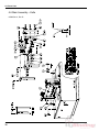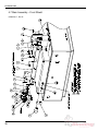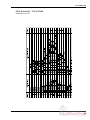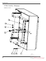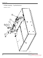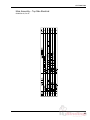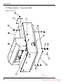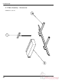
1
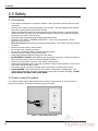
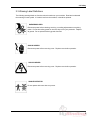
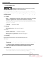
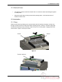
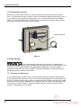
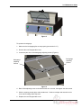
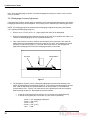
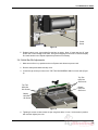
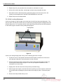
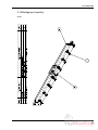
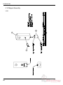
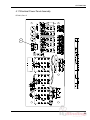
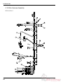
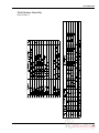
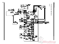
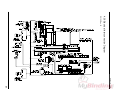
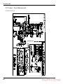
CHALLENGE
SPARTAN 150SA
PAPER CUTTER
Service Manual
Provided By
http://www.MyBinding.com
http://www.MyBindingBlog.com
Serial Numbers 041001 & Up
TECHNICAL SERVICE
AND PARTS MANUAL
SPARTAN 150 SA
SEMI-AUTOMATIC
PAPER CUTTER
Sold and Serviced by
The Challenge Machinery Company
6125 Norton Center Drive
Norton Shores, MI. 49441
www.challengemachinery.com
F.150-T
Dec. 2004
1.0 Introduction
1.0 Introduction
THIS MANUAL is designed to help you get the most from your Challenge equipment. Keep this
manual in a safe, convenient place for quick reference by operators and service personnel.
SAFETY ALERT! This symbol means CAUTION: Personal safety
instructions! Pay special attention to the instructions in bold type. Personal injury may result if the
precautions are not read and followed.
FOR PARTS AND SERVICE contact the Authorized Challenge Dealer from whom you purchased
your machine. Use the illustrations and parts lists at the back of this manual to identify the correct
parts needed. Always give the SERIAL NUMBER and MODEL of your machine to insure the correct
parts are sent as soon as possible.
Challenge® is a registered trademark of The Challenge Machinery Company• 6125 Norton Center Drive • Norton Shores, MI
49441-6081
Copyright© 2004 by The Challenge Machinery Company. All rights reserved. Printed in the U.S.A
2
1.0 Introduction
TABLE OF CONTENTS
1.0 Introduction....................................................................................................................................... 2
2.0 Safety ............................................................................................................................................... 4
2.1 Precautions .................................................................................................................................. 4
2.2 Power Lockout Procedure............................................................................................................ 4
2.3 Warning Label Definitions ............................................................................................................ 5
3.0 Maintenance Guide .......................................................................................................................... 7
3.1 Routine Maintenance ................................................................................................................... 8
3.1.1 Weekly .................................................................................................................................. 8
3.1.2 Monthly ................................................................................................................................. 8
3.1.3 Yearly.................................................................................................................................... 8
3.2 Cleaning ....................................................................................................................................... 8
3.2.1 Table ..................................................................................................................................... 8
3.2.2 Display Panel........................................................................................................................ 8
3.2.3 Machine Exterior................................................................................................................... 9
3.3 Lubrication.................................................................................................................................... 9
3.3.1 Clamp.................................................................................................................................... 9
3.3.2 Backgauge Leadscrew ....................................................................................................... 10
3.4 Adjustments ............................................................................................................................... 10
3.4.1 Squaring the Backgauge .................................................................................................... 10
3.4.2 Backgauge Accuracy Adjustment....................................................................................... 12
3.4.3 Knife Bar Gib Adjustments ................................................................................................. 13
3.4.4 Knife Leveling Adjustment .................................................................................................. 14
3.4.5 Backgauge Gib Adjustments .............................................................................................. 15
3.4.6 Leadscrew Collars .............................................................................................................. 16
3.4.7 Line Light Adjustment ......................................................................................................... 17
3.4.8 Front Guard Switch Adjustment.......................................................................................... 18
3.4.9 Knife Up Limit Switch Adjustment....................................................................................... 19
3.4.10 Knife Down Limit Switch Adjustment ................................................................................ 20
3.4.11 Backgauge Encoder/Belt Adjustment ............................................................................... 21
3.4.12 Re-engaging the Knife Pull-Down Gear ........................................................................... 22
3.5 Troubleshooting ......................................................................................................................... 24
4.0 Parts Lists....................................................................................................................................... 26
4.1 Main Assembly – Backgauge Bracket ....................................................................................... 26
4.2 Main Assembly – Leadscrew ..................................................................................................... 28
4.3 Main Assembly – Knife Drive ..................................................................................................... 30
4.4 Main Assembly – Bottom Side Electrical ................................................................................... 32
4.5 Main Assembly – Clamp ............................................................................................................ 34
4.6 Main Assembly – Knife .............................................................................................................. 36
4.7 Main Assembly – Front Shield ................................................................................................... 38
4.8 Main Assembly – Backgauge..................................................................................................... 40
4.9 Main Assembly – Top Side Electrical......................................................................................... 42
4.10 Main Assembly – Covers and Labels....................................................................................... 44
4.11 Main Assembly – Accessories ................................................................................................. 46
4.12 Motor and Gearbox Assembly – Sheet 1 ................................................................................. 48
4.13 Motor and Gearbox Assembly – Sheet 2 ................................................................................. 49
4.14 Motor and Gearbox Assembly – Sheet 3 ................................................................................. 50
4.15 Backgauge Assembly .............................................................................................................. 51
4.16 Magnet Assembly..................................................................................................................... 52
4.17 Electrical Power Panel Assembly ............................................................................................ 53
4.18 Wire Harness Assembly........................................................................................................... 54
4.19 Electrical Schematic................................................................................................................. 56
4.20 Electrical Interconnection Diagram .......................................................................................... 57
4.21 Label – Fuse Replacement ...................................................................................................... 58
4.22 Optional Floor Stand Assembly ............................................................................................... 59
3
2.0 Safety
2.0 Safety
2.1 Precautions
•
•
•
•
•
•
•
•
•
•
•
•
•
•
•
•
This machine is designed for one-person operation. Never operate the machine with more than
one person.
Safe use of this machine is the responsibility of the operator. Use good judgment and common
sense when working with and around this machine.
Read and understand all instructions thoroughly before using the machine. If questions remain,
contact the dealer from which you purchased this machine. Failure to understand the operating
instructions may result in personal injury.
Only trained and authorized people should operate this machine.
DO NOT ALTER SAFETY GUARDS OR DEVICES. They are for your protection. Severe
personal injury may result.
Disconnect power before cleaning or performing maintenance. See Section 2.2 Power Lockout
Procedure.
Observe all caution labels on this machine.
Be sure the cutter is properly grounded.
Be sure there is sufficient power to operate the cutter properly.
Observe all caution plates mounted on this cutter.
Keep foreign objects off table and away from cutter blade.
BE EXTREMELY CAREFUL when handling and changing the cutter knife. Severe lacerations or
dismemberment could result from careless handling procedures.
Keep the floor around the cutter free of trim, debris, oil and grease.
When replacing hydraulic parts, loosen the connections slowly to release pressure. Never loosen
connections with the machine running.
If the cutter sounds or operates unusually, have it checked by a qualified service person.
CRUSH HAZARD, keep hand and fingers from under the clamp when clamping paper. Use
Jogging Aid to load paper, and use the backgauge to push paper out before unloading. DO NOT
REACH UNDER THE KNIFE AND CLAMP AREA!
2.2 Power Lockout Procedure
For maximum safety while making adjustments or repairs to your machine, be sure to disconnect
power to the machine. Disconnect the power plug from its socket
Figure 1 - Main Power Disconnect
4
2.0 Safety
2.3 Warning Label Definitions
The following warning labels are found at various locations on your machine. Read and understand
the meaning of each symbol. If a label is lost from the machine, it should be replaced.
HAZARDOUS AREA
Disconnect power before cleaning, servicing, or making adjustments not requiring
power. Do not alter safety guards or devices; they are for your protection. Replace
all guards. Do not operate with any guards removed.
SHOCK HAZARD
Disconnect power before removing cover. Replace cover before operation.
SHOCK HAZARD
Disconnect power before removing cover. Replace cover before operation.
SINGLE OPERATOR
Do not operate with more than one person.
5
2.0 Safety
!OJO!
This Este simbolo de alerta de seguridad significa ¡ OJO ! INSTRUCCIONES DE SEGURIDADPERSONAL. Lea las instrucciones porque se refieren a su
seguridad personal. Fall de obedecer las instrucciones que siguen podria resultar en lesiones
corporales.
•
•
•
•
•
•
•
•
•
•
•
•
•
•
•
•
•
•
•
•
Esta maquina, junto con sus mecanismos de seguridad, esta disenada para ser manejada por
UNA SOLA PERSONA a la vez. Jamas debe ser manejada por mas de una persona al mismo
tiempo.
La seguridad es la responsabilidad del operario que usa esta maquina.
LEA DETENIDAMENTE el manual de instrucciones y las PRECAUCIONES DE SEGURIDAD
antes de poner a funcionar la cortadora. Pidale a su supervisor una copia.
El manejo de la guillotina debe estar exclusivamente a cargo de personal entrenado y autorizado
para ello.
NO MODIFIQUE LOS MECANISMOS DE SEGURIDAD, estan ahi para su proteccion no deben
ni modificarse ni quitarse.
DESCONECTE LA CORRIENTE ELECTRICA antes de proceder a hacerle servicio de limpieza,
engrasar, o de hacer adjustes que no requieren corriente. Trabe el interruptor en la posicion
OFF (apagado); vea “Procedimiento para cortar la corriente electrica” al pie de esta pagina.
Eche llave a la guillotina y quite la llave cuando la maquina no esta en operacion; vea “Corriente
electrica”.
Asegurese de que la guillotina este debidamente a tierra. Vea “Conexion de la fuerza electrica”.
Verifique el voltaje y asegurese de que este sea suficiente para el debido funcionamiento de la
guillotina.
Preste atencion a todas las placas con advertencias instaladas en esta guillotina.
No permita que objetos estranos esten en la mesa o cerca de la cuchilla cortadora.
TENGA SUMO CUIDADO al tocar y cambiar la cuchilla. Heridas severas y hasta
desmembramiento pueden resultar del manejo sin cuidado o negligente.
El suelo alrededor de la guillotina debe mantenerse despejado y libre de recortes, desperdicios,
aceite y grasa.
Al haber la necesidad de reemplazar partes hidraulicas, afloje todas las conexiones poco a poco
para dejar escapar la presion. Jamas debe aflojarse conexiones mientras la maquina este
andando.
Si la guillotina empezara a sonar o trabajar diferentemente a lo acostumbrado, desconectela y
consulte la seccion “Troubleshooting” (Reparador) de este manual. Si no es posible corregir el
problema, llame a su servicio autorizado para que le examinen la maquina.
PELIGRO DE MACHUQUE - Mantenga manos y dedos fuera de la agarradera mientras sujeta el
papel. Use el calibrador trasero y su rueda de mano para empujar el papel cortado. NO PONGA
SUS MANOS BAJOLA CUCHILLA O AREA DE LA AGARRADERA.
NO OPERE SIN LAS GUARDAS PROTECTORAS!
¡ OJO ! PRECAUCION -
Como proceder para desconectar
la corriente electrica.
Para maxima seguridad durante ajustes y reparaciones de su maquina, verifique bien que el interruptor principal
de control de corriente al cual la maquina esta conectada, este desconectado. El interruptor deba ser puesto en
la posicion “OFF” (desconectado) y se debe poner un candado en la anilla. La llave del candado debe ser
guardada por la persona que estara efectuando los trabajos de servicio o de reparacion en la guillotina.
Desconecte la corriente electrica antes de proceder a hacer cualquier ajuste o reparacion o de efectuar el
engrase en cualquier maquina.
6
3.0 Maintenance Guide
3.0 Maintenance Guide
NOTICE
The instructions on the following
pages are for the use of trained
service personnel only!
Attempting to perform repair and
replacement procedures without
proper training may cause
machine damage or operator
injury!
PARTS CUSTOMERS: The Challenge Machinery Company provides parts with the express
understanding that they are to replace parts found missing or no longer serviceable on
equipment designed and/or manufactured by Challenge. The Challenge Machinery
Company assumes no liability for any modification or alteration to any Challenge products,
and any such modification or alteration to any Challenge product is not authorized by The
Challenge Machinery Company. Any modification or alteration of any Challenge product
will void any remaining warranty.
7
3.0 Maintenance Guide
3.1 Routine Maintenance
DISCONNECT POWER before making any adjustments or lubricating.
See page 4, SAFETY PRECAUTIONS, for Power Lockout Procedure.
A clean, lubricated machine will run longer, smoother, cut more accurately, with less downtime and
fewer costly repairs. Schedule lubrication both early in the day and early in the week. This allows the
lubricants to work into the machine. Lubrication at the end of the day or week allows the lubricants to
run off without as much benefit to the machine. The following guidelines will help you set up a regular
maintenance schedule:
3.1.1 Weekly
•
Clean — Clean off old, dirty excess grease. Remove the top cover and clean accumulated
dust off knife bar and gib areas. Built-up dust can increase wear to components.
•
Hardware — Remove top cover and bottom cover to check all nuts and bolts for tightness.
Loose hardware is the cause of most component wear and in the electrical area could cause
short circuits and/or shock.
•
Lubrication — See section 3.3 page 9
3.1.2 Monthly
•
Backgauge Squaring — See section 3.4.1 page 10
3.1.3 Yearly
•
Knife Bar Gib Adjustment — See section 3.4.3 page 13
•
Backgauge Accuracy Adjustment — See Section 3.4.2 page 12
3.2 Cleaning
Before cleaning inside machine, turn power off and disconnect power cord.
3.2.1 Table
•
The front table should be wiped down periodically. Use a non-abrasive cleaner along with a
protective wax.
•
The rear table cover and front shield may be cleaned with glass cleaner or a mild water
based detergent. Some petroleum-based solvents may damage the Plexiglas.
3.2.2 Display Panel
•
8
The display panel should be cleaned with a mild water based detergent applied to a damp
cloth or paper towel. Petroleum based solvents will damage the display.
3.0 Maintenance Guide
3.2.3 Machine Exterior
•
The machine’s exterior should be cleaned with a non-abrasive water based detergent applied
to a damp cloth.
•
Always be careful when cleaning around safety warning labels. Use limited amounts of
cleaners in those areas.
3.3 Lubrication
3.3.1 Clamp
Send the knife down by activating a cut cycle and when the knife reaches the bottom, release only
the right cut button and turn off the power before releasing the left cut button. Disconnect the power
cord and remove the top cover for access. Wipe off any old or excess grease. Apply grease to the
areas shown in Figure 2 and Figure 3 below.
Grease
Grease
Figure 2
Grease Leadscrew
Figure 3
9
3.0 Maintenance Guide
3.3.2 Backgauge Leadscrew
With the top cover ON, place machine on a flat level surface on it’s left side and remove bottom
cover. Use any brand-name type of grease or light oil to lubricate backgauge leadscrew (Figure 4). It
may be helpful to use a small brush to apply grease. Note: the leadscrew may be lubricated with
grease or oil. Oil has a tendency to run off and must be lubricated more frequently; grease tends to
collect paper dust and must be cleaned off periodically.
Grease Leadscrew
Figure 4
3.4 Adjustments
Some of the following tests require the machine to be operational for
checking and adjusting. Be very careful that tools and other people are clear of moving parts and that
the cutter is not accidentally operated while adjustments are being made. Whenever possible,
disconnect the power and lock it out (see SAFETY PRECAUTIONS, page 4) unless the directions
specifically require the machine to be powered.
3.4.1 Squaring the Backgauge
To test if the backgauge is square, place a small lift of paper against the left side of the backgauge
(but not against the side guide) and make a cut. Now, leave the backgauge in the same position, flip
the lift over and push it against the right side of the backgauge (but not against the side guide). Make
another cut to see if any of the paper will trim off (Figure 5). Run two checks, one starting on the left
and moving to the right; the other, moving from the right to the left. If paper is trimmed in either
sequence, the backgauge is out of square.
10
3.0 Maintenance Guide
Figure 5
To square the backgauge:
1. Make sure the backgauge gibs are set properly (see section 3.4.5 ).
2. Remove the rear Plexiglas table cover.
3. Loosen the jam nuts on the backgauge adjusting screws. (Figure 6).
Backgauge
Adjusting
Screws
Backgauge
Adjusting
Screws
Figure 6
4. Back off the adjusting screw on the side that the trim occurred, then tighten the other screw.
5. With the squaring screws tight, make another test. Continue to adjust and test until no trim
occurs when testing either sequence.
6. Replace the rear Plexiglas table cover.
11
3.0 Maintenance Guide
Note: Once the backgauge is square, check the backgauge accuracy (see section 3.4.2 ) to make
sure it is accurate.
3.4.2 Backgauge Accuracy Adjustment
If the backgauge position readout does not match the actual measurement between the knife and the
backgauge, the accuracy can be adjusted. The accuracy can be checked by the following procedure:
NOTE: The backgauge should be squared before attempting to adjust the accuracy. (See Section
3.4.1 Squaring the Backgauge, page 10.)
1. Place a 1/4 to 1/2” lift of 8-1/2 x 11 “ paper against the center of the backgauge.
2. Using the backgauge position readout, bring the lift up to the 10.00” position and make a cut.
Then move the backgauge up to 5.00” and make another cut.
3. Take a sheet from the center of each lift and compare them to each other. The cutter will
always space accurately between cuts (in this case the 10” and 5” cuts) whether the overall
accuracy is correct of not (Figure 7). The front stack will be a true 5”, but the paper left
against the backgauge will not be if the backgauge position is inaccurate.
Accurate
Questionable
Figure 7
4. The backgauge accuracy can be corrected by adjusting the preset screw attached to the
bottom of the backgauge nut assembly (Figure 8). Turn off power and disconnect the power
cord. With the top cover ON, place machine on a flat level surface on it’s left side and
remove bottom cover. Place a 3/16” Allen wrench in the preset screw and hold in position
while loosening the jam nut. Now adjust the screw as follows:
•
•
If test pile is short (back pile is less than 5”), turn screw out (counterclockwise).
If test pile is long (back pile is more than 5”), turn screw in (clockwise).
1/4 turn = .012” backgauge adjustment
1/3 turn = .016 (1/64”)
1/2 turn = .024”
2/3 turn = .032” (1/32”)
1 turn = .048”
12
3.0 Maintenance Guide
Preset
Screw
Figure 8
5. Replace bottom cover, lay machine flat, and turn on power. Note: If power was not off, reset
power now or else reading will be false. Bring the backgauge to the front to reset the display
and make another test. Repeat adjustment procedure if necessary.
3.4.3 Knife Bar Gib Adjustments
1. Make sure knife is in up position and turn off power and disconnect power cord.
2. Remove clamp hand wheel and top cover.
3. Loosen the gib screw jam nuts on the TOP TWO GIB SCREWS ONLY on each side (Figure
9).
Top Two
Knife Bar
Gib Screws
Top Two
Knife Bar
Gib Screws
Bottom
Knife Bar
Gib Screw
Bottom
Knife Bar
Gib Screw
Figure 9
4. Tighten gib screws so that screws are just snug then add a 1/8 turn. Hold screws in position
with tool then tighten jam nuts.
13
3.0 Maintenance Guide
5. Replace top cover, plug in power cord, turn power on, and start a cut cycle.
6. When knife is all the way down, release right cut button only and switch off power.
7. Now with the knife in the down position, disconnect power cord, remove top cover, and
repeat gib screw adjustment for the BOTTOM GIB SCREW on each side.
8. Replace top cover and clamp handle.
3.4.4 Knife Leveling Adjustment
If knife cuts through one side of paper and not the other, the knife level may need adjustment. First
check to make sure the knife is all the way up in knife bar by looking through the viewing holes in the
knife bar (Figure 10). If it is not all the way up, loosen the knife screws and use knife lifter assembly
to raise knife up tight. Recheck knife by cutting through paper.
Viewing Holes
Figure 10
If knife is not cutting through paper evenly, use the following procedure to adjust:
1. Flip the cut stick to a new position and raise the knife depth by several turns of the screw
(see Operator’s Manual for more information on how to do this).
2. Place a few sheets of paper over the entire cut stick, and set the knife depth so that it just
cuts through the bottom sheet of paper on one side (see Operator’s Manual for more
information on how to do this).
3. Slightly loosen the left-most knife screw (but keep somewhat snug).
4. With the paper still in place, send the knife down by making a cut and continue to hold in the
left cut button while releasing the right cut button and turning off power. Disconnect power
cord.
5. Remove the clamp handle and top cover.
14
3.0 Maintenance Guide
6. Slightly loosen the remaining (5) knife screws, keeping them somewhat snug.
7. Adjust the knife leveling screw (Figure 11) that corresponds with the side of the knife which
does not cut all the way through. Tug on the paper while adjusting and stop when the bottom
sheet is cut all the way through.
Knife Leveling Screws
Figure 11
8. Tighten the (5) accessible knife screws, replace top cover and clamp handle, restore power
to machine, raise up knife, and tighten (1) remaining knife screw.
3.4.5 Backgauge Gib Adjustments
If the backgauge does not stay square or moves up and down or back and forth when jogging paper
against it, the backgauge gib screws may be loose or worn.
To Adjust:
1. Turn off the power and disconnect the power cord.
2. With the top cover ON, place machine on a flat level surface on it’s left side and remove
bottom cover.
3. Loosen the two outside gib screw jam nuts (Figure 12, page 16).
15
3.0 Maintenance Guide
Backgauge
Gib Screw
Backgauge
Gib Screw
Figure 12
4. Tighten the two nylon set screws until they just touch the guide. Do not over-tighten or they
could cause the backgauge to bind. Lock in position with jam nuts. The center screw is a
spring loaded plunger and should not need adjustment.
5. Run the backgauge back and forth the length of the table and check for any binding.
Readjust if necessary. Replace the bottom cover and lay machine flat.
3.4.6 Leadscrew Collars
Any play in the backgauge leadscrew should not cause inaccuracies in cutting. However, excessive
play can be eliminated by adjusting the leadscrew collars as follows:
1. Turn off the power and disconnect the power cord.
2. With the top cover ON, place machine on a flat level surface on it’s left side and remove
bottom cover.
3. Loosen the two screws attached to each collar (Figure 13).
16
3.0 Maintenance Guide
Leadscrew
Collars
Figure 13
4. Make sure there is a slight gap between the front hand crank and the machine, slide collars
up tight against the nylon washers and tighten the collar screws.
5. Check to make sure the hand crank turns freely with no play.
6. Replace bottom cover and lay machine flat.
3.4.7 Line Light Adjustment
The line light can be adjusted if necessary as follows:
1. Remove the top clamp hand wheel and top cover.
2. Loosen the three line light mounting screws (Figure 14, page 18).
17
3.0 Maintenance Guide
Line Light
Mounting
Screws
Figure 14
3. Place a white sheet of paper over the cut stick and turn the power on to activate the line light.
Note: 24V is being supplied to line light board while power is on.
4. Slide the line light assembly forward or backward to get a single, crisp line.
5. Tighten the screws and turn power off. Replace the cover and hand wheel.
3.4.8 Front Guard Switch Adjustment
The front guard interlock switch must be adjusted correctly in order for machine to function properly
and safely.
To adjust:
1. Turn off the power and disconnect the power cord.
2. Remove clamp handle and top cover.
3. Loosen (2) screws and nuts that mount the front guard switch as seen in Figure 15. Make
sure the front guard is lowered and slide the switch forward or backward until the actuator
lines up with the flat on the hinge rod (Figure 15). Leave a very slight gap (about the
thickness of a strip of paper) between the actuator and flat.
18
3.0 Maintenance Guide
Hinge Rod
Mounting
Screws
Figure 15
4. Tighten screws, replace cover and clamp handle.
5. Test to make sure machine works properly, using the test found at the end of this manual.
3.4.9 Knife Up Limit Switch Adjustment
If the knife up limit switch becomes loose or needs adjustment, adjust as follows:
1. Turn off the power and disconnect the power cord.
2. With the top cover ON, place machine on a flat level surface on it’s left side and remove
bottom cover.
3. If the knife pull-down gear is disengaged, engage it now. See Section 3.4.12 Re-engaging
the Knife Pull-Down Gear, page 22.
4. Loosen bracket mounting screws (Figure 16, page 20), and slide bracket such that mounting
screws become located in the center of the slots. Then tighten screws, and check to make
sure screws mounting switch are tight also.
Note: Apply temporary thread lock to bracket mounting screws to prevent screws from
coming loose during operation.
19
3.0 Maintenance Guide
Mounting Screws
Figure 16
5. Replace bottom cover, lay machine flat, and turn on power. Make a cut. Check position of
knife – USE CAUTION, THE KNIFE EDGE IS VERY SHARP. The edge of a new knife
should be above the bottom of the clamp when the knife and clamp are in the “up” positions.
If the knife edge is below the clamp, repeat the adjustment procedure described above, and
move the bracket slightly in the slots to allow the knife to come up further. NOTE: the knife
should not be able to come up so far that the gears become disengaged – or damage to the
machine could result.
3.4.10 Knife Down Limit Switch Adjustment
The down limit switch is normally adjusted by the operator from the exterior of the machine. No
internal adjustments can be made, but the switch can be checked to ensure that it is functioning
properly.
To check switch assembly:
1. Turn off the power and disconnect the power cord.
2. With the top cover ON, place machine on a flat level surface on it’s left side and remove
bottom cover.
3. Check all bracket and switch hardware to make sure they are tight (Figure 17).
20
3.0 Maintenance Guide
Bracket Mounting Screws
Limit Switch
Switch Bracket
Figure 17
4. Check to make sure the switch bracket slides freely on the mounting bracket.
5. Check condition of spring.
6. Replace bottom cover and lay machine flat.
3.4.11 Backgauge Encoder/Belt Adjustment
The backgauge encoder system reads the position of the backgauge, and sends the information to
the display. The encoder uses a belt and pulley system to read the actual position of the backgauge.
The following checks and adjustments may be necessary to ensure the backgauge display reads
properly and accurately:
1. Turn off the power and disconnect the power cord.
2. With the top cover ON, place machine on a flat level surface on it’s left side and remove
bottom cover.
3. Inspect the encoder bracket and mounting screws (Figure 18, page 22). Make sure the
bracket is not bent, and that the screws are tight.
21
3.0 Maintenance Guide
Belt
Encoder
Pulley
Bracket Mounting
Screws
Figure 18
4. Inspect the belt and make sure it is tight. If it is not, loosen the (2) screws at the rear of the
machine, pull belt tight, then tighten the screws.
5. Make sure the pulley is properly lined up with the belt (Figure 18). If not, the position of the
pulley can be adjusted by loosening the pulley set screw, then slide the pulley into place, then
tighten the set screw.
6. Now move the backgauge forward and backward through its full range of motion, checking to
make sure the pulley tracks along belt properly.
7. Replace bottom cover and lay machine flat.
3.4.12 Re-engaging the Knife Pull-Down Gear
If the knife pull-down gear becomes disengaged, the following procedure must be followed in order to
properly re-engage it:
1. Turn off the power and disconnect the power cord.
2. With the top cover ON, place machine on a flat level surface on it’s left side and remove
bottom cover.
3. Disengage the motor brake by moving the brake lever counterclockwise (when looking at
lever from front of machine) as shown in Figure 19.
22
3.0 Maintenance Guide
Disengage Brake
Figure 19
4. Now move the gears in the directions shown in Figure 19. Some machines are equipped with
gears that have a small stub on them which can be used to turn the gear using a pliers or
wrench if necessary. If the larger gear cannot be moved by hand, carefully tap on it with a
rubber hammer, or carefully pry it with a long bar. Be very careful not to damage the gear
teeth. Rotate the gears so that at least one whole tooth is engaged (Figure 20).
Engage Brake
Figure 20
5. Engage the motor brake by moving the brake lever clockwise (when looking at lever from
front of machine) as shown in Figure 20).
NOTE: The motor brake must be engaged before machine is powered up or damage to
the machine could result.
23
3.0 Maintenance Guide
6. Check to make sure the up and down limit switches are positioned properly to prevent gears
from becoming disengaged again (See Section 3.4.9 page 19 and Section 3.4.10 page 20).
7. Replace bottom cover and lay machine flat.
3.5 Troubleshooting
Problem
1. The machine will not
power up – no display,
no line light, and
machine will not cycle.
Possible Cause
a) Power cord is disconnected.
b) Main power switch/circuit
breaker is off.
c) Blown fuse on main circuit
board.
d) Disconnected wires inside
machine.
e) No power at electrical outlet.
2. Display and line light are
on, but machine will not
cycle.
a) Front guard is open.
b) Front guard has not been
opened and closed since
previous cut cycle.
c) Front guard switch needs
adjustment.
d) Knife limit switches need
adjustment.
e) Disconnected wires inside
machine.
f) Faulty cut button.
g) Faulty main circuit board.
3. Power is on, but
backgauge display is
blank.
a) Disconnected wires inside
machine.
b) Faulty display circuit board.
a) Plug in cord.
b) Turn power switch/circuit
breaker on.
c) Check fuse, replace if blown.
d) Check for wires that are
disconnected from main circuit
board, power cord, etc.
e) Check outlet. Repair or use
another outlet.
a) Close front guard.
b) Open and close front guard.
c) See Section 3.4.8 Front Guard
Switch Adjustment, page 18.
d) See Sections 3.4.9 Knife Up
Limit Switch Adjustment, page
19 and 3.4.10 Knife Down
Limit Switch Adjustment, page
20.
e) Check for wires that are
disconnected from main circuit
board, cut buttons, etc.
f) Check continuity of cut buttons
at circuit board connection.
Replace if necessary.
g) Replace main circuit board.
a) Check for wires that are
disconnected from main circuit
board, display circuit board,
etc.
b) Replace display circuit board.
4. Backgauge display
shows: “----“.
a) Backgauge has not been
preset.
a) Preset Backgauge by bringing
backgauge to front of machine
(see Operator’s Manual for
more info).
5. Power is on, but line light
does not light up.
a) Disconnected wires inside
machine.
a) Check for wires that are
disconnected from main circuit
board, line light circuit board,
etc.
b) Replace line light circuit board.
b) Faulty line light circuit board.
24
Solution
3.0 Maintenance Guide
Problem
6. Backgauge display is
inaccurate.
Possible Cause
a) Backgauge accuracy needs
adjustment.
b) Encoder malfunction.
c) Faulty display circuit board.
7. Knife cuts deeper on one
side than the other.
a) Knife is not seated all the way
up in knife bar.
b) Knife level is not set properly
8. The machine strains
through a cut.
a) Dull knife.
b) Paper clamped too tight.
c) Inadequate power source.
Solution
a) See Section 3.4.2 Backgauge
Accuracy Adjustment, page 12.
b) Check encoder system (see
Section 3.4.11 Backgauge
Encoder/Belt Adjustment, page
21) or replace encoder.
c) Replace display circuit board.
a) Loosen knife screws and use
knife lifter assembly to raise
knife up tight.
b) See Section 3.4.4 Knife
Leveling Adjustment, page 14.
a) Change the knife with a new or
sharpened one. See
Operator’s Manual for knife
changing information and
instructions.
b) Apply less force on clamp
handle when clamping paper.
c) The electrical outlet may not
have sufficient power if other
equipment is operating on the
same line. Check voltage
and/or try another outlet on a
different line.
9. Concave cutting – ends
wide, center narrow.
a) Excessive moisture at edges
of paper.
a) Keep paper in dry location.
10. Concave cutting –
variation from top to
bottom.
a) Soft paper not firmly clamped.
a) Apply more force on clamp
handle when clamping.
b) Change the knife with a new or
sharpened one. See
Operator’s Manual for knife
changing information and
instructions.
11. Motor runs at start up
and does not stop
running.
a) Knife up limit switch out of
adjustment.
a) See Section 3.4.9 Knife Up
Limit Switch Adjustment, page
19
12. Knife coasts after motor
stops.
a) Motor brake is disengaged.
a) Engage motor brake (see
Section 3.4.12 Re-engaging
the Knife Pull-Down Gear,
page 22.
b) Replace motor brake. See
Section 4.14 page 50 for part
number. Replacement
instructions included with part.
b) Knife dull or incorrectly
ground.
b) Motor brake is worn out.
25
4.0 Parts Lists
4.0 Parts Lists
4.1 Main Assembly – Backgauge Bracket
60000 Sht. 1, Rev. B
26
4.0 Parts Lists
Main Assembly – Backgauge Bracket
60000 Sht. 1, Rev. B
27
4.0 Parts Lists
4.2 Main Assembly – Leadscrew
60000 Sht. 2, Rev. B
28
4.0 Parts Lists
Main Assembly – Leadscrew
60000 Sht. 2, Rev. B
29
4.0 Parts Lists
4.3 Main Assembly – Knife Drive
60000 Sht. 3, Rev. B
30
4.0 Parts Lists
Main Assembly – Knife Drive
60000 Sht. 3, Rev. B
31
4.0 Parts Lists
4.4 Main Assembly – Bottom Side Electrical
60000 Sht. 4, Rev. B
32
4.0 Parts Lists
Main Assembly – Bottom Side Electrical
60000 Sht. 4, Rev. B
33
4.0 Parts Lists
4.5 Main Assembly – Clamp
60000 Sht. 5, Rev. B
34
4.0 Parts Lists
Main Assembly – Clamp
60000 Sht. 5, Rev. B
35
4.0 Parts Lists
4.6 Main Assembly – Knife
60000 Sht. 6, Rev. B
36
4.0 Parts Lists
Main Assembly – Knife
60000 Sht. 6, Rev. B
37
4.0 Parts Lists
4.7 Main Assembly – Front Shield
60000 Sht. 7, Rev. B
38
4.0 Parts Lists
Main Assembly – Front Shield
60000 Sht. 7, Rev. B
39
4.0 Parts Lists
4.8 Main Assembly – Backgauge
60000 Sht. 8, Rev. B
40
4.0 Parts Lists
Main Assembly – Backgauge
60000 Sht. 8, Rev. B
41
4.0 Parts Lists
4.9 Main Assembly – Top Side Electrical
60000 Sht. 9, Rev. B
42
4.0 Parts Lists
Main Assembly – Top Side Electrical
60000 Sht. 9, Rev. B
43
4.0 Parts Lists
4.10 Main Assembly – Covers and Labels
60000 Sht. 10, Rev. B
44
4.0 Parts Lists
Main Assembly – Covers and Labels
60000 Sht. 10, Rev. B
45
4.0 Parts Lists
4.11 Main Assembly – Accessories
60000 Sht. 11, Rev. B
46
4.0 Parts Lists
Main Assembly – Accessories
60000 Sht. 11, Rev. B
47
4.0 Parts Lists
4.12 Motor and Gearbox Assembly – Sheet 1
60005 Sht. 1, Rev. A
48
4.0 Parts Lists
4.13 Motor and Gearbox Assembly – Sheet 2
60005 Sht. 2, Rev. A
49
4.0 Parts Lists
4.14 Motor and Gearbox Assembly – Sheet 3
60005 Sht. 3, Rev. A
50
4.0 Parts Lists
4.15 Backgauge Assembly
60203
51
4.0 Parts Lists
4.16 Magnet Assembly
60052
52
4.0 Parts Lists
4.17 Electrical Power Panel Assembly
EE-3061, Rev. B
53
4.0 Parts Lists
4.18 Wire Harness Assembly
EE-3116, Rev. C
54
4.0 Parts Lists
Wire Harness Assembly
EE-3116, Rev. C
55
E-3062
4.19 Electrical Schematic
4.0 Parts Lists
56
4.20 Electrical Interconnection Diagram
E-3125 Rev. B
4.0 Parts Lists
57
4.0 Parts Lists
4.21 Label – Fuse Replacement
S-1781-129, Rev. B
58
4.0 Parts Lists
4.22 Optional Floor Stand Assembly
60065, Rev. B
59