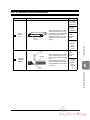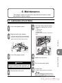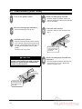
1
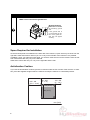
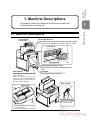
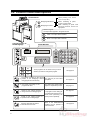
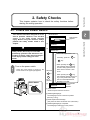
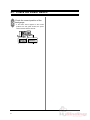
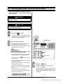
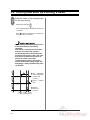
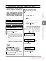
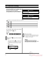
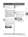
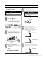
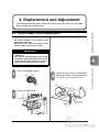
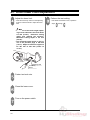
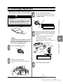
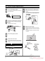
Standard APC45
Programmable
Paper Cutter
Instruction Manual
Provided By
http://www.MyBinding.com
http://www.MyBindingBlog.com
PAPER CUTTER
APC- 45
Important Information
• This manual is designed to help you to install, operate and maintain the APC-45 Paper
Cutter. Please read and understand this manual, and keep it in a safe and convenient
place.
• Do not operate the APC-45 until you read and understand the instructions in this
manual.
• Horizon International Inc. shall not be liable for incidental consequential damages
resulting from: improper or inadequate maintenance by the customer unauthorized
modification or misuse, or operation outside of the environmental specifications for the
product.
• Horizon International Inc. pursues a policy of continuing improvement in design and
performance of the product. Therefore, the product design and specifications are
subject to change without prior notice and without our legal obligation.
• All rights are reserved. No part of this manual may be photocopied, reproduced or
translated to another language without the prior written consent of Horizon
International Inc.
081208/APC45/06E/NO/HF/KY/F7/I9/P7
UM204023-06
I
Safety Precautions
Safety precautions are indicated in this manual as follows:
The term WARNING indicates a potentially hazardous situation which, if not
avoided, could result in death or serious injury.
The term CAUTION indicates a potentially hazardous situation which, if not
avoided, may result in serious injury, or damage to the machine.
This symbol indicates a note which includes important information. Follow
the note to operate the machine safely.
This symbol indicates a prohibited action. Do not perform any prohibited
action.
This symbol indicates an essential procedure. Follow the procedure to
operate the machine safely.
Important
Attention
Note
Additional
Information
• This lists the range of acceptable values and operating
conditions.
• This information will help you to avoid problems with the
machine or help you learn how to operate the machine.
• Refer to this note when you operate the machine.
• This explains a mechanism in the machine.
Horizon International Inc. cannot anticipate every possible situation that might involve a
potential hazard. The instructions in this manual and warning labels on the machine are
therefore not all inclusive.
All equipment shall be locked out or tagged out to protect against accidental or inadvertent
operation when such operation could cause injury to personnel. Do not attempt to operate
any switch, valve, or other energy isolating device where it is locked or tagged out.
Do not operate the machines when any covers are removed.
Some of the drawings in this manual show the machine with the covers removed to
explain some of the details inside the machine. Never operate the machine with the covers
removed.
II
Safety Operation Precautions
WARNING for Operation
This machine must be operated by just one person at a time.
Various safety devices are installed on this machine. If any of these are bypassed or
removed, this may cause severe accident and personal injury.
Each operator should be familiar with the safety instructions, be aware of the potential
dangers, and have sufficient knowledge of how to manage an accident. Anyone who
does not have this training should not operate the machine.
Before starting the machine, be sure to perform the checks described in Chapter 2:
Safety Checks. When loading the sheets on the table and setting the sheet position, get
your foot off from the foot pedal.
CAUTION for Operation
Do not cut anything besides paper. This may damage the machine.
If you turn the power switch Off, wait 10 seconds or more before turning it On again.
Do not get on, or step on the foot pedal with great force. The machine may be damaged.
CAUTION for Maintenance
Do not apply too much grease. Filled grease may stain the paper.
III
CAUTION for Installation
Make sure to connect the ground wire.
Ground Terminal
Make sure to connect
the accessory ground
wire.
If the ground wire is
not connected, the letters on the guide window may not appear
correctly.
Space Required for Installation
As the electrical parts are installed on the lower left of the machine, repair work may be done from the
right side. Allow about 600 to 700 mm (23.7 to 27.6") on the left side of the machine if it is possible.
In addition, when you adjust the knife angle, you need to insert the tool into the machine from the left
side. Allow about 200 mm (7.9”) on the left side.
Allow about 100 to 200 mm (4 to 7.9”) on the right side and the rear.
Antivibration Cushion
If you use the antivibration cushions, place the cushions under the four corners of the machine. In addition, place the supplied wedges under the machine to keep the machine in a horizontal position.
600 - 700
(23.7" - 27.6")
100 - 200
(4" - 7.9")
100 - 200
(4" - 7.9")
770 (30.4")
880 (34.7")
Front
mm (inch)
IV
CONTENTS
Important Information ........................................................................................ I
Safety Precautions ............................................................................................ II
Safety Operation Precautions ......................................................................... III
1. Machine Descriptions .................................................................................. 1
1-1 Machine Descriptions ............................................................................................. 1
1-2 Control Panel Descriptions ..................................................................................... 2
1-3 Cutting Mechanism ................................................................................................ 3
2. Safety Checks ............................................................................................... 5
2-1 Check the Power Switch ........................................................................................ 5
2-2 Check the Cutting Buttons ..................................................................................... 7
2-3 Check the Beam Light Sensors .............................................................................. 8
2-4 Check the Control Panel ........................................................................................ 9
2-5 Check the Foot Pedal ........................................................................................... 10
3. Operation Procedures ............................................................................... 11
3-1 Cutting Operation on the Cutting Line .................................................................. 11
3-2 Cutting Operation by Entering a Value ................................................................. 14
3-3 Cutting Operation by Programmed Value ............................................................ 17
3-4 Function Cutting ................................................................................................... 20
3-5 Compression Operation ....................................................................................... 22
3-6 Creating a Cutting Program ................................................................................. 23
3-7 Checking the Counter .......................................................................................... 30
3-8 Knife Replacement Message ............................................................................... 31
4. Replacement and Adjustment.................................................................... 33
4-1 Knife Lower Limit Adjustment ............................................................................... 33
4-2 Knife Angle Adjustment ........................................................................................ 35
4-3 Cutting Stick Replacement ................................................................................... 37
5. Troubleshooting .......................................................................................... 39
5-1 An Error Message Appears .................................................................................. 39
5-2 Problems and Remedies ...................................................................................... 40
5-2-1 Stain, Diagonal Line, Pressing Mark and Uncut of the Sheets ............................... 40
6. Maintenance ................................................................................................ 43
6-1 Lubrication ............................................................................................................ 43
7. Appendix...................................................................................................... 45
7-1 Specifications ....................................................................................................... 45
7-2 Accessories .......................................................................................................... 46
V
This page is intentionally left blank.
VI
Machine
Descriptions
1. Machine Descriptions
Machine Descriptions
This chapter explains the positions and functions of each part
of this machine in this manual.
1-1 Machine Descriptions
Control Panel
See next page.
Beam Light Sensors
Cutting motion does not start even if pressing both cutting buttons
when the invisible light between the beam light sensors is blocked.
Knife Cover
Side Guide
Cutting Stick
Cutting Buttons (Upper Inside)
These buttons must be pressed simultaneously to cut
sheets.
Power Switch
Foot Pedal
When turning on the power switch, turn
the key clockwise.
When this machine is not in use,
remove the key. An authorized person
should keep the key so that other people can not run the machine.
Step on this pedal to lower the clamp.
Side Guides
Power Cable
Ground Terminal
Backgauge
Make sure to connect
the ground wire here.
This backgauge is the back stop
of sheets to be cut.
1
1-2 Control Panel Descriptions
Control Panel
When pressing once, moves
by 0.1 mm (0.005”)
Backgauge Backward
Backgauge Forward
When continuing to press,
moves at a low speed.
When continuing to press more
than three seconds, moves at a
high speed.
Numeric Keypad:
The input value appears in the guide window.
Current Position of
the Backgauge
C
Clear = The input value is cleared.
Ent
Enter = The input value is entered.
Guide Window
M1
M2
Three programs can be stored. Call your local
dealer if you want to change the program.
See page 20.
M3
Cut sheets according to the current
= position of the backgauge without
using program and function key.
Cut sheets according to the
= programmed value.
For short-run job and same
job pattern.
See page 14.
For cutting many sheets which
require a complicated process.
See page 17.
Create a new cutting program or
= change the saved cutting program.
Create a new cutting program to
= repeat the same cutting length.
Only the clamp lifts and lowers.
= The knife does not move.
2
If a program for the cutting job
is created and memorized, it is
useful when performing the
same process repeatedly.
Spine of the saddle-stitched
booklets can be pressed to
reduce the bulk.
See page 23.
See page 29.
See page 22.
Machine
Descriptions
1-3 Cutting Mechanism
3
Knife Holder
After the clamp presses the
sheets, this knife holder lowers
and the sheets are cut.
Knife Cover
Clamp
M
2 Foot Pedal Clamp
When the foot pedal (No.7) is stepped,
only this part lowers.
Knife
Cutting Mechanism
4
1
When the cutting buttons are pressed, this
clamp presses the sheets first.
5
Cutting Stick
The knife cuts into this stick and the
sheets are cut. If the groove of the
cutting stick becomes deep, turn it
by 90 degrees.
7
Foot Pedal
When this foot pedal is stepped
on, the clamp lowers depending
on the stepping depth.
Use this to check the cutting
position.
M
This knife cuts the sheets. If the
knife edge becomes dull, replace
with a new one.
6
Backgauge
This backgauge moves to the
set
position.
The
length
between this backgauge and
the knife will be the cutting
length. This value is indicated
as current position.
• The lowering limit position of the knife (No.2) can be adjusted.
Adjust if the knife height becomes smaller because of resharpening. See page 33.
• The cutting stick (No.4) is cut by the knife and ditched.
1
8
2
7
3
6
4
When the knife cuts the same position of the cutting stick and the
groove of the cutting stick becomes deep, the bottom sheet may
remain uncut.
In this case, turn the cutting stick and use another face.
The cutting stick provides two surfaces per face.
Therefore, up to eight times - four faces can be used totally.
5
3
This page is intentionally left blank.
4
Safety Checks
2. Safety Checks
This chapter explains how to check the safety functions before
starting the cutting operation.
2-1 Check the Power Switch
WARNING
If you notice a problem while making the
safety checks, do not try to correct the
problem by yourself. If the machine is not
working correctly, it may cause severe personal injury. Please notify your local
dealer.
Guide Window
(1)
Horizon
ROM Version
appears.
APC-45
VX.XX
(2)
Horizon
LOADING . . .
(3)
Check the Power Switch
This machine has been designed to be as
safe as possible. However, if an accident
occurs, it can cause severe personal
injury. Before using the machine, always
perform the safety checks listed in this
chapter.
APC-45
REPLACE KNIFE
PRESS "Ent"
• If the knife replacement is not
necessary, press the
C
or
Ent key.
Turn on the power switch.
- When the power switch is turned on, the
screen shown to the upper right appears.
When the
C
• When pressing the C key,
this message does not appear
until the cutting operation has
been done for another 1,000
times.
or
Ent
key is
pressed,
Power Switch
OFF
ON
When pressing the Ent key,
this message appears when turning on the power switch again.
See “3-8 Knife Replacement
Message” for details.
(4)
400.0mm
check that this
screen
appears.
(1) Initial Screen:
When the power switch is turned on.
(2) Initializing Backgauge:
The backgauge moves to the home position
(400 mm [17.00”]).
(3) Knife Replacement Message:
(Only when the knife cuts sheets over 2,000 times.)
(4) Initializing Backgauge Completed:
The backgauge reaches the home position.
5
2-1 Check the Power Switch
Check the current position of the
backgauge.
- If the value “400.0” appears in the current
position box and guide window, the power
switch and the software are OK.
400.0mm
6
In the following steps, if the machine does not
operate as explained “the machine is OK”,
stop the check immediately.
Press both cutting buttons continuously.
- The cutting process is as follows:
1. The clamp lowers.
Turn on the power switch.
2. The knife lowers.
- When the initialization is completed, the current position value (=400.0) appears.
3. The knife lifts.
Safety Checks
2-2 Check the Cutting Buttons
4. The clamp lifts.
Keep pressing both cutting buttons
after the cutting process.
Cutting Buttons
Press only left cutting button continuously.
- If the clamp and the knife do not move, the
machine is OK.
Press only right cutting button continuously.
- If the clamp and the knife do not move, the
machine is OK.
Press left cutting button first and
then press right cutting button more
than 0.5 seconds later.
- If the clamp and the knife do not move, the
machine is OK.
- When the cutting process is completed, the
clamp and the knife stop at the upper limit
and do not move. If the machine does not
start the next cutting process, the machine is
OK.
Press both cutting buttons, and
then release one of them when the
cutting process starts.
- If the clamp and the knife stop when releasing
one of your hands, the machine is OK.
- Also check by releasing another hand.
- Press both cutting buttons again. The clamp
and the knife will return to the starting position.
If the knife is at the lower limit, the
machine does not stop even if releasing
one of your hands.
Instead, the knife lifts and then the
clamp lifts.
If the knife is not at the upper limit (=
the knife is in the middle position), the
motor reverses when one of the cutting
buttons are pressed and another one is
pressed more than 0.5 seconds later.
- Also press the cutting buttons in the reverse
order and if the clamp and the knife do not
move, the machine is OK.
7
Check the Cutting Buttons
- If the clamp and the knife move in this order,
the machine is OK.
2-3 Check the Beam Light Sensors
Turn on the power switch.
Press both cutting buttons.
- When the initialization is completed, the current position value (=400.0) appears.
- Continue to press the cutting buttons while the
obstacle is on the table.
- If the clamp and the knife do not move, the
machine is OK.
Check the beam sensor.
- If the LED on the receiver on the right sensor
illuminates red, the machine is OK.
Obstacle
Beam Light Sensor
Receiver
Cutting Buttons
Beam
Beam Light Sensor
Emitter
LED
When the beam light
is received
= Red
If the optional cutting section cover is
installed,
Turn on the power switch.
- When the initialization is completed, the current position value (=400.0) appears.
Block the beam light between sensors.
Open the cutting section cover.
- The beam light is about 77 mm (3.0”) above
the table. Place any obstacle on the table to
block the beam. (Do not place the obstacle
under the knife.)
M1 M2 M3
Cutting
Section
Cover
- If the LED on the receiver “does not” illuminate, the machine is OK.
Cutting Buttons
77mm
(3.0")
Obstacle
Receiver
Press both cutting buttons.
- Continue to press the cutting buttons while the
cutting section cover is open.
- If the clamp and the knife do not move, the
machine is OK.
8
2-4 Check the Control Panel
button.
Check the Control Panel
Press the
Safety Checks
In the following steps, if the machine does
not operate as explained “the software is
OK”, stop the check immediately.
- Press the button once and release.
Continue to press the
button.
- If the value of the current position of the backgauge decreases by 0.1 mm (0.005”), the
software is OK.
- If the backgauge moves at low speed in the
arrow direction for three seconds, then it
moves at high speed, the software is OK.
Press the
Input 200 (mm) / 7.000 (inch).
button.
- If the value increases more than 0.1, then
decreases gradually and finally the value
increases by 0.1, the software is OK.
- Check that the
input the
Because the screw has a little play,
when the backgauge is moved backward, it is moved backward beyond the
input depth first, and then forward.
the
7
button is selected and
2
.
or
0
0
0 Ent
0
keys (mm) /
0 Ent keys (inch),
using the numeric keypad.
- If the backgauge moves and the value “200.0 /
7.00” appears in the box of the current position of the backgauge, the software is OK.
When inputting the value 200, the input
of figures after the decimal point is not
necessary.
9
2-5 Check the Foot Pedal
In the following steps, if the machine does not
operate as explained “the machine is OK”,
stop the check immediately.
The foot pedal is used for the following purpose.
1. To check the cutting position
The cutting position can be checked before
actual cut by stepping on the foot pedal and
lowering the clamp.
2. Sheet Press
Swelled or curled sheets can be cut more
accurately by stepping on the foot pedal and
pressing them by the clamp. (The sheets can
be cut by pressing the cutting buttons while
stepping on the foot pedal.)
Step on the foot pedal slowly.
- If the clamp lowers smoothly, the machine is
OK.
CAUTION
Do not get on, or step on the foot
pedal with great force. The machine
may be damaged.
Release the foot pedal.
- If the clamp lifts to the upper limit, the machine
is OK.
10
3. Operation Procedures
Cutting Operation Cutting the sheets by aligning them to the present cutting line
on the Cutting Line
(light shows the cutting line).
2
Cutting Operation
by Entering a Value
Cutting the sheets by entering a value directly or positioning using the backgauge forward and backward buttons.
3
Cutting Operation by
Programmed Value
Program a complicated cutting process beforehand and
cutting the sheets by recalling the program.
4
Function Cutting
M1
Cutting the sheets by recalling the frequent cutting process using the M1 to M3 buttons.
3-1 Cutting Operation on the Cutting Line
Press the
button.
- The LED on the upper left of this button is illuminated and shows that the “cutting operation
by entering a value” is selected.
WARNING
This machine must be operated by just one
person at a time.
CAUTION
Place the sheets.
Do not cut anything besides paper. This
may damage the machine.
- The maximum cutting height is 60 mm (2.36”).
- Align the sheets using the backgauge and the
side guide.
Do not pile the narrow sheets high.
Place the sheets on the other side so that
the clamp does not incline widely.
11
Cutting Operation on the Cutting Line
There are four
ways of cutting
operation
as
shown to the
right.
1
Operation Procedures
This chapter explains four cutting operation procedures, compression
operation, program and how to indicate the counter.
3-1 Cutting Operation on the Cutting Line
Align the desired cutting position
with the cutting line.
Press both cutting buttons at the
same time and keep pressing them.
- Align the desired cutting position with the cutting line by pressing the backgauge forward
button.
- The cutting operation starts.
- Release your hands from the cutting buttons
when the knife returns to the upper limit.
Align the cutting position by moving the
backgauge forward.
If the backgauge is moved backward, the
sheets should be aligned with the backgauge every time.
Cutting Buttons
The cutting position can be checked also
by stepping on the foot pedal and lowering the clamp.
Backgauge Forward and Backward
Buttons
- Pressing once: Moves by 0.1 mm (0.005”)
- Pressing continuously within three seconds:
Moves at low speed
- Pressing continuously for three seconds
or more: Moves at high speed
- Press both cutting buttons at the
same time. If they are not pressed
within 0.5 seconds, the machine does
not operate.
- If your hand is released from one of
the cutting buttons while the knife is
lowering toward the lower limit, the
knife stops at that position.
- Release your hands from the cutting
buttons when the cutting operation is
completed. The secondary cutting
operation dose not start even if pressing them continuously after the cutting process.
The clamp and the knife move as follows
during the cutting operation.
- The clamp presses the sheets and the knife
lowers.
- The knife lifts and the clamp lifts.
Foot Pedal
1
12
2
3
4
3-1 Cutting Operation on the Cutting Line
Remove the cut sheets.
Operation Procedures
- The value of the cutting length appears in the
box of the current position of the backgauge.
If you memorize this value, the sheets can be
cut for the same length at the next time.
- If the
button is pressed, the cut sheets is
pushed forward.
(The cutting position changes. If you memorizes the value, input the value using the
numeric keypad. The backgauge moves to
the set position.)
Cutting Operation on the Cutting Line
Current Position
of the Backgauge
Numeric Keypad
13
3-2 Cutting Operation by Entering a Value
This section explains the cutting operation
when entering a value directly without
using program.
WARNING
This machine must be operated by just one
person at a time.
CAUTION
Do not cut anything besides paper. This
may damage the machine.
Press the
button.
- The LED on the upper left of this button is illuminated and shows that the “cutting operation
by entering a value” is selected.
LED
Guide Window
Input the cutting length.
- Input using the numeric keypad. The input
value appears in the guide window.
- The value can be input in the range of 40 mm
to 450 mm (1.575” to 17.715”).
For inch version, only “0” and “5” can be
input to the third decimal place.
If the value out of range is input, “OUT OF
RANGE“ appears on the guide window. In
this case, press the
correct value.
Ent key and input the
7
8
9
4
5
6
1
2
3
-
=
+
0
C
Clear
Ent
Enter (Input)
- (For mm version) The value can be input up to
the first decimal place.
- (For inch version) The value can be input up
to the third decimal place.
- If the value after the decimal point is “0”, the
decimal point and “0” is not necessary to be
input.
- The calculation keys can be used.
Example: If cutting the sheet whose length is
594 mm into half, press the
5
9
4
2
Ent keys. The
backgauge moves to the position of 297 mm
14
Press the
Ent
key.
- The value is entered and the backgauge
moves to the position.
- When the backgauge moves to the input position, the “beep” sounds and the value is indicated in the box of the current position of the
backgauge.
3-2 Cutting Operation by Entering a Value
- When the automatic push-out mode is
selected, the backgauge moves forward after
every cutting to push the sheets forward.
- Press the
button. The icon of the "Auto-
Press both cutting buttons at the
same time and keep pressing them.
- The cutting operation starts.
- Release your hands from the cutting buttons
when the knife reaches the lower limit and
starts to lift.
matic Push-Out Mode" appears on the guide
window.
- When pressing the
button again, the
automatic push-out mode is canceled.
Operation Procedures
Set the automatic push-out mode.
- The push-out length is 50 mm (1.97", fixed).
However, the push-out length may be less
than 50 mm (1.97") according to the cutting
length (less than 90 mm [3.54”]).
Automatic Push-Out Mode Icon
Place the sheets.
- The maximum cutting height is 60 mm (2.36”).
- Arrange the sheets by aligning them with the
backgauge and side guide.
Do not pile the narrow sheets high.
Place the sheets on the other side so that
the clamp does not incline widely.
- Press both cutting buttons at the
same time. If they are not pressed
within 0.5 seconds, the machine does
not operate.
- If your hand is released from one of
the cutting buttons while the knife is
lowering toward the lower limit, the
knife stops at that position.
- Release your hands from the cutting
buttons when the cutting operation is
completed. The secondary cutting
operation dose not start even if pressing them continuously after the cutting process.
The clamp and the knife move as follows
during the cutting operation.
- The clamp presses the sheets and the knife
lowers.
- The knife lifts and the clamp lifts.
1
2
3
4
15
Cutting Operation by Entering a Value
Cutting Buttons
3-2 Cutting Operation by Entering a Value
Enter the value of the cutting length
for the next cutting.
- Repeat from the step
.
- If the cutting operation is finished, remove the
cut sheets.
- If the
button is pressed, the cut sheets on
the rear side move forward.
The movement of the backgauge when it
moves backward for positioning:
(Example)
If the sheet is cut to 200.0 mm (11.000”)
and next cut to 300.0 mm (14.000”),
the backgauge moves backward to the
position of 307.0 mm (14.275”) first, and
then moves forward to the position of
300.0 mm (14.000”) and stops.
The backgauge moves in this way to
ensure the accurate cutting length. The
backgauge is always positioned by moving forward.
1
1 The backgauge
moves backward
to 307.0 mm
(14.275”),
2
3 Stops at
300.0 mm
(14.000”)
200.0 300.0 307.0
(11.000")(14.000")(14.275")
3
0
16
2 Moves
and
forward
3-3 Cutting Operation by Programmed Value
WARNING
This machine must be operated by just one
person at a time.
Input the course number.
- Input using the numeric keypad.
Example:
When recalling the course number 3, press
the
3 and Ent keys.
The job name of the course number
should be written down when programming.
To check the process of the course,
press the
CAUTION
Do not cut anything besides paper. This
may damage the machine.
button.
- When the course number is input, the backgauge moves to the position of the step 1 and
the machine becomes ready to be operated.
When the course
number 3 is input,
Press the
button.
- The LED on the upper left of the program button is illuminated and shows that the “cutting
operation by programmed value” is selected.
- The course number appears in the guide window.
Course Number:
“Course” is a program composed of a
series of the cutting steps. The course is
managed using the number 1 through 30.
COURSE:3
1:320.0
This message appears
on the screen and the
backgauge moves to the
position of the step 1
(320.0).
1/3
2:280.0
When the incorrect course
number is input,
E13 : NOT AVAILABLE
PRESS "Ent"
This message
appears on the
screen.
Press the Ent key and input the
correct number again.
LED
When the empty course
number is input,
COURSE : 20
NO MEMORY
appears.
To cancel the cutting operation by programmed
SELECT COURSE (1-30)
1
Course number
can be input.
(“1” appears as
default value.)
value, press the
Operation Procedures
- The value can be input in the range of 1 to 30.
button.
17
Cutting Operation by Programmed Value
This section explains the cutting operation
performed following the programmed process.
When performing the same cutting process
repeatedly, or performing a complicated
cutting process, input each value of the
process in order beforehand, so that the
backgauge automatically moves into the
position for each step and makes the operation efficient.
Refer to “3-6 How to Program” for the programing and correcting the program.
3-3 Cutting Operation by Programmed Value
Place the sheets.
- The maximum cutting height is 60 mm (2.36”).
- Arrange the sheets by aligning them with the
backgauge and side guide.
Do not pile the narrow sheets high.
Place the sheets on the other side so that
the clamp does not incline widely.
- When the step 1 is completed, the backgauge
pushes out the sheets for 50 mm (2”) and
moves to the position of the step 2.
Push-Out:
“Push-out” means to move the cut
sheets forward before the following process by moving the backgauge forward.
The push-out length of this machine is 50
mm (2”). However, if the cutting length is
smaller than 90 mm (3.575”), the backgauge pushes out the sheets to the position of 40 mm (1.575”).
Perform the cutting operation of the
step 1.
- Press both cutting buttons.
- Release your hands from the cutting buttons
when the knife reaches the lower limit and
starts to lift.
The clamp and the knife move as follows
during the cutting operation.
- The clamp presses the sheets and the knife
lowers.
- The knife lifts and the clamp lifts.
1
2
3
4
Cutting Buttons
- Press both cutting buttons at the
same time. If they are not pressed
within 0.5 seconds, the machine does
not operate.
- If your hand is released from one of
the cutting buttons while the knife is
lowering toward the lower limit, the
knife stops at that position.
- Release your hands from the cutting
buttons when the cutting operation is
completed. The secondary cutting
operation dose not start even if pressing them continuously after the cutting process.
Perform the cutting operation of the
step 2.
- Place and align the sheets to the backgauge
and side guide.
- Check that the following message appears on
the guide window, and press both cutting buttons.
- When the step 2 is completed, the backgauge
moves to the position of the step 3. (If the
backgauge moves backward, it pushes out
the sheets first and moves backward.)
COURSE : 3
2:280.0
Step 2
18
2/8
3:120.0
Step 3
3-3 Cutting Operation by Programmed Value
Repeat the cutting operation in the
same way.
COURSE : 3
8:50.0
8/8
If nothing appears
here, the backgauge
moves to the position
of the step 1.
Cutting Operation by Programmed Value
Last Cutting
Step
Operation Procedures
- When the last cutting step is completed, the
backgauge moves to the position of the step 1
automatically.
19
3-4 Function Cutting
This section explains how to recall the cutting job performed most frequently using
the function keys M1 through M3.
Three programs can be saved. Call the service representatives of your local dealer.
WARNING
This machine must be operated by just one
person at a time.
CAUTION
Do not cut anything besides paper. This
may damage the machine.
Write down your own program value for your reference.
M1
M2
M3
The following steps explain the function
cutting using the
key.
M3
Example:
M3 :
1:209.0
2:296.0
3:2 9 5 . 0
Place the sheets.
- The maximum cutting height is 60 mm (2.36”).
Press the M3 key of the function
keys.
- The program saved in
M3
is recalled. The
backgauge moves to the position of the step 1
and the machine becomes ready to be operated.
Guide Window
M3
1:209.0
Step 1
20
1/3
2:296.0
Step 2
- Arrange the sheets by aligning them with the
backgauge and side guide.
Do not pile the narrow sheets high.
Place the sheets on the other side so that
the clamp does not incline widely.
3-4 Function Cutting
Perform the cutting operation of the
step 1.
Repeat the cutting operation in the
same way.
- When the step 1 is completed, the backgauge
moves to the position of the step 2.
Perform the cutting operation of the
step 2.
- Place and align the sheets to the backgauge
and side guide.
- Check that the following message appears on
the guide window, and press both cutting buttons.
Perform the cutting operation of the
last step.
- Place and align the sheets to the backgauge
and side guide.
- Check that the following message appears on
the guide window, and press both cutting buttons.
- When the step 3 is completed, the backgauge
moves to the position of the step 1.
Guide Window
M3
3:295.0
Last Step
3/3
If nothing appears here, the
backgauge moves to the
position of the step 1.
- When the step 2 is completed, the backgauge
moves to the position of the step 3. (If the
backgauge moves backward, it pushes out
the sheets first and moves backward.)
Guide Window
M3
2:296.0
2/3
3:295.0
Current Step
Next Step
21
Function Cutting
- Press both cutting buttons at the
same time. If they are not pressed
within 0.5 seconds, the machine does
not operate.
- If your hand is released from one of
the cutting buttons while the knife is
lowering toward the lower limit, the
knife stops at that position.
- Release your hands from the cutting
buttons when the cutting operation is
completed. The secondary cutting
operation dose not start even if pressing them continuously after the cutting process.
Operation Procedures
- Press both cutting buttons.
3-5 Compression Operation
This section explains how to reduce the
bulk of the saddle-stitched booklets using
the pressure of the clamp.
WARNING
This machine must be operated by just one
person at a time.
Press the
Step on the foot pedal.
- Press the swelled part of the booklet by stepping on the foot pedal temporarily.
CAUTION
Do not get on, or step on the foot
pedal with great force. The machine
may be damaged.
button.
- The LED on the upper left of the compression
operation button is illuminated and shows that
the “compression operation” is selected.
LED
Press both cutting buttons.
- Only the clamp lowers and compresses the
bulk. (The knife does not lower.)
Move the backgauge to the front.
- Move the backgauge so that the spine of the
booklets can be placed under the clamp.
- The clamp still compresses the booklet after
the cutting buttons are released.
The clamp lowers.
The clamp presses.
Place the swelled booklet.
- Place the booklet so that the spine touches
the backgauge.
Do not pile the narrow sheets high.
Place the sheets on the other side so that
the clamp does not incline widely.
22
Press both cutting buttons again.
- The clamp lifts and the compression operation
is completed.
The clamp lifts.
3-6 Creating a Cutting Program (Input)
Operation Procedures
When repeating a complicated cutting job,
it is helpful to create and save the process
to a cutting program. (Up to thirty programs can be saved.)
This section explains how to create or correct the cutting programs.
WARNING
This machine must be operated by just one
person at a time.
CAUTION
Do not cut anything besides paper. This
may damage the machine.
Press the
Input the course number for saving
the program.
button.
- The LED on the upper left of the program
memory button is illuminated and shows that
the “program memory” is selected.
- For example, this procedure explains how to
save a new program into the course number 14.
- “SELECT COURSE (1-30)” appears in the
guide window.
- Press the 1 4 Ent keys on the
numeric keypad. The guide window will be
ready to input the cutting length value for the
step 1.
LED
When the course number 14 is
input,
COURSE14
1/0
1: 0
SELECT COURSE (1-30)
1
The course
number can
be input.
The value for
the step 1 is
ready to be
input.
The job name of the course number
should be written down when programming.
To check the process of the course,
press the
button.
23
Creating a Cutting Program (Input)
[Creating a New Program]
3-6 Creating a Cutting Program (Input)
Input the cutting length for the step 1.
Input the cutting length for the step 2.
- In this step, the cutting length of the step 1
should be 320.0 for example.
- In this step, the cutting length of the step 2
should be 280.0 for example.
- Press the 3 2 0 Ent keys on the
numeric keypad. The backgauge moves to
the position of 320.0.
- Press the 2 8 0 Ent keys on the
numeric keypad. The backgauge moves to
the position of 280.0.
- Check that the current position of the back-
- Check that the current position of the back-
gauge is “320.0” and press the
again.
Ent key
gauge is “280.0” and press the Ent key
again. The step 3 is ready to be input.
- The step 1 is set and the step 2 is ready to be
input.
When the value for the
step 1 is input as 320, the
backgauge moves to the
position of 320.0.
Ent
When the
pressed again,
COURSE14
2/0
1 : 320 . 0
2:0
key is
The value for
the step 2 is
ready to be
input.
If the value after the decimal point is “0”,
the decimal point and “0” is not necessary to be input.
COURSE14
2/0
1 : 320.0
2:0
The value for
the step 2 is
ready to be
input.
When the 280 is input in
the step 2,
COURSE14
1 : 320.0
2/0
2:280.0
And when the Ent
pressed again,
COURSE14
3/0
2 : 280.0
3:0
key is
The value for
the step 3 is
ready to be
input.
Input the cutting length for the step
3 or after as well.
- In the following procedures, the last process
should be step 13 for example.
If the value for the step 3
or after is input,
COURSE14
appear.
COURSE14
14
14
14
COURSE14
12 : 100.0
24
0
4
40
0
13 0
/0
13 : 0
3-6 Creating a Cutting Program (Input)
Input the cutting length for the last
step.
Ent key while the value is “0” in
Operation Procedures
- Press the
step 14.
After the value for the last
step 13 is input,
COURSE14
14 / 0
13 : 90 . 0
14 : 0
The value for
the step 14 is
ready to be
input.
Creating a Cutting Program (Input)
Press the Ent key while the
value is “0” to complete the
program.
Save the program.
- Press the Ent key on the confirmation
screen below and finish creating the program.
- The program cutting mode starts and the LED
on the
button is illuminated.
When the Ent key is pressed
while the input value is 0,
The exit confirmation
screen appears.
EXIT?
Y : "Ent"
N : "C"
When the Ent key is pressed,
The memory
confirmation screen
MEMORIZE?
Y : "Ent"
N : "C" appears.
When the Ent key is pressed,
COURSE14
1:320.0
1/13
2:280.0
The program of the course
number 14 starts.
25
3-6 Creating a Cutting Program (Correct)
This section explains how to correct the
saved program.
Example: When enlarging the cutting
length by 0.5 mm at the step 3, course
number 5.
COURSE : 5
2:260
3 /10
3:249.5
Enlarging by 0.5mm
250.0
[Correcting the Saved Program]
Press the
Input the course number to correct.
button.
- The LED on the upper left of the program
memory button is illuminated and shows that
the “program memory” is selected.
- “SELECT COURSE (1-30)” appears in the
guide window.
- In this step, for example, input the course
number 5.
- Press the 5 Ent keys on the numeric
keypad. The step 1 of the course number 5
appears on the guide window as shown
below.
LED
Input the
number 5.
COURSE : 5
1 /10
1:420.0
SELECT COURSE (1-30)
1
26
The course
number can
be input.
course
3-6 Creating a Cutting Program (Correct)
- Press the Ent key for the step 1 which will
not be corrected.
When the Ent key is pressed, the backgauge moves to the position of the step.
- Repeat the same procedure and move to step 3.
When the Ent key is pressed again, the
next step appears.
Repeat this and move to the step 3.
Correct the value of the step 3.
COURSE : 5
2 : 260.0
3 /10
3 : 249.5
- Press the C key to cleat the old value
“249.5”, input the new value “250” and press
Ent key.
Ent
key is pressed,
the value for the step 4
is ready to be input.
4 /10 Press the Ent key
4 : 270.0 and move to the next
COURSE : 5
3 : 250.0
step, and repeat this
procedure.
1 0 : 130.0
- Press the Ent key on the confirmation
screen to the right and finish the correction of
the program.
ton is illuminated.
but-
11: 0
Ent key is pressed,
EXIT?
Y : "Ent"
N : "C"
- The program cutting mode of the course number 5 starts and the LED of the
When “0” is input in the
the
COURSE : 5 11/10 last step 11 and
Save the program.
The exit confirmation
screen appears.
When the
MEMORIZE?
Y : "Ent"
N : "C"
The memory confirmation screen appears.
When the
COURSE : 5
1 :420.0
Ent key is pressed,
Ent key is pressed,
1/10
2 :260.0
The program of the course
number 5 starts.
27
Creating a Cutting Program (Correct)
the
Press the C key and
clear the old value
“249.5.”
After the new value
“250” is input and the
Operation Procedures
Show the step 3 to correct.
3-6 Creating a Cutting Program (Delete)
This section explains how to delete the
saved program.
Example: When deleting course number 5.
COURSE : 5
2:260
3 /10
3:249.5
[Deleting the Saved Program]
Press the 0 key and the
the numeric keypad.
Press the
button.
Ent
key on
- “EXIT?” appears in the guide window.
- The LED on the upper left of the program
memory button is illuminated and shows that
the “program memory” is selected.
When the Ent key is pressed
after “0” is input,
- “SELECT COURSE (1-30)” appears in the
guide window.
EXIT?
Y : "Ent"
N : "C"
LED
Press the
Ent
The exit confirmation
screen appears.
key.
- “MEMORIZE?” appears in the guide window.
SELECT COURSE (1-30)
1
The course
number can
be input.
When the
MEMORIZE?
Y : "Ent"
N : "C"
Ent key is pressed,
the memory confirmation screen appears.
Input the course number to delete.
- In this step, for example, input the course
number 5.
- Press the 5 Ent keys on the numeric
keypad. The step 1 of the course number 5
appears on the guide window as shown
below.
Press the
1 /10
1:420.0
28
key.
- “NO MEMORY” appears in the guide window.
This is the end of the procedure for deleting
the program.
Input the course number 5.
COURSE : 5
Ent
When the
COURSE : 5
NO MEMORY
Ent key is pressed,
the program is deleted.
3-6 Creating a Cutting Program (Repeat Cutting Program)
When using the
button, the program
to cut the sheets for the same length continuously can be easily input.
This section explains how to use the repeat
function.
- The “repeat” mark appears on the guide window.
- When you press the
button again, the
“repeat” mark disappears.
Example:
420 mm sheets are cut to 410 mm, and then
the rest of the sheets are divided evenly by
90 mm.
5
The value for step 1 is
ready to be input.
1/0
1:0
Operation Procedures
Press the
button and set the
repeat of the step.
5
1/0
1 : 410.0
90 50
The value of step 2 is
ready to be input.
2/0
2:0
5
50
0
140
90
230
90
320
410
10 90
5
The value of step 2 is
ready to be input.
(With repeat mark)
2/0
2:0
Input 410 for the step 1.
- Press the 4 1 0 Ent keys. The
backgauge moves to the input position and
stops.
Input the repeat cutting length 90.
- Check the position and press the
The step 2 can be input.
Ent key.
- Input the
5
2/0
9
0 Ent keys.
The repeated cutting
length is input.
2 : 90.0
29
Creating a Cutting Program (Correct)
420
3-6 Creating a Cutting Program (Repeat Cutting Program)
Input “0” to the step 3.
- When the 0 Ent keys are input to the cutting length, the confirmation screen appears.
When the Ent key is pressed, the program
is determined and the cutting program starts.
3/0
Press the Ent key
while the value is “0”.
3:0
EXIT?
Y : "Ent"
N : "C"
The exit
confirmation
screen appears.
When the
Ent key is pressed,
MEMORIZE?
Y : "Ent"
N : "C"
The memory
confirmation
screen appears.
When the
Ent key is pressed,
COURSE : 5
1 :410.0
30
1/2
2 :90.0
Cutting operation
by
programmed
value starts.
Press the
button.
Press the C key of the numeric
keypad.
- The counter indicates the value for two seconds.
2,000 times of cutting operation is used
as a target for knife replacement.
The knife condition depends on the type
of sheets to cut.
If prime condition of the knife, good finishing, or accurate trimming is required,
it is recommended to replace the knife
every 500 times of cutting operation.
TOTAL
KNIFE
How many times
the sheets are
cut since the
machine
was
new.
10050
510 / 2000
How many times
the sheets are cut
since the last knife
replacement.
2,000:
Reference
for replacing the
knife.
31
Checking the Counter
This section explains how to indicate the
frequency of the total cut since the
machine was new, or since the last knife
replacement.
Refer to the value for the knife replacement.
Operation Procedures
3-7 Checking the Counter
3-8 Knife Replacement Message
When the cutting operation has been done
over 1,000 times since the last knife
replacement, the message shown at lower
right appears turning on the power switch.
This message informs you the knife
replacement timing. This message does
not mean that the knife must be replaced. If
the knife is still sharp enough to cut, you
can keep using the knife.
[If replacing the knife]
- Ask the replacement of the knife to your local
dealer.
Turning on the power
switch...
Horizon
APC-45
VX.XX
[If not replacing the knife]
If not coming up this message until
the cutting operation has been
done over 1,000 times again
Horizon
LOADING . . .
Message for
Knife
Replacement
APC-45
REPLACE KNIFE
PRESS "Ent"
C
- Press the
C
key.
- The machine comes up this message again after
another 1,000 times of cutting operation.
- The postponement of another 1,000 times can be
done repeatedly.
If indicating this message each
time the power switch is turned on
- Press the
32
Ent key.
7
8
9
4
5
6
1
2
3
-
=
+
0
400.0mm
key
C
Ent
Ent key
4. Replacement and Adjustment
This chapter explains how to adjust the knife lower limit, the knife angle and
how to replace the cutting stick.
The lowest position of the knife can be
adjusted mechanically.
Adjust the lower limit if the knife is worn
and the bottom sheet remains uncut.
WARNING
• A single operator must perform the
adjustment.
• There will be some procedures to turn off
the power switch below. Make sure to turn
off the power switch. Otherwise, moving
parts can cause severe personal injury.
Turn off the power switch.
OFF
ON
Loosen two lock nuts of knife height
adjusting screws using the wrench.
- The right lock nut is a left-handed screw.
Open the lower cover.
Lower Cover
Loosen
399 mm
(15.71")
Lock Nuts
Wrench
33
Knife Lower Limit Adjustment
Replacement and Adjustment
4-1 Knife Lower Limit Adjustment
4-1 Knife Lower Limit Adjustment
Adjust the lower limit.
Perform the test cutting.
- Insert the accessory driver into the adjusting
hole and rotate the shaft to adjust the lower
limit.
- If the sheet still remains uncut, repeat the
- 1/6 rotation of the knife height adjusting screws lifts/lowers the knife about
0.6 mm (0.024"). Excessive cutting
depth may damage the machine.
Maximum cutting depth is 0.5 mm
(0.019").
- The standard length shown in the figure in the previous page is 399 mm
(15.71"). Adjust so that this length will
be 397 mm to 400 mm (15.63" to
15.74").
Lower
Lift
Adjusting Hole
Accessory
Driver
Fasten two lock nuts.
Close the lower cover.
Turn on the power switch.
34
steps
through
.
4-2 Knife Angle Adjustment
Adjust the knife angle if part of the sheets
remain uncut as shown in the figure below.
Turn on the power switch.
• A single operator must perform the
adjustment.
• There will be some procedures to turn off
the power switch below. Make sure to turn
off the power switch. Otherwise, sharp
knife can cause severe personal injury.
OFF
ON
KNIFE REPLACE MODE
Uncut
Some Sheets at
the Bottom
LOWER CLAMP
Press the cutting buttons and keep
pressing until you hear a beeping
sound.
Replacement and Adjustment
- The indication [REPLACE MODE] is shown
on the guide window and then it changes to
[LOWER CLAMP].
WARNING
- Release the cutting buttons after only the
clamp lowers and stops.
- The indication [TURN OFF POWER
REPLACE KNIFE] is shown on the guide window.
Cutting Buttons
Turn off the power switch.
OFF
Knife Angle Adjustment
If only bottom sheets remain uncut, the
problem can be improved also by lowering the knife position. Refer to “4-1
Knife Lower Limit Adjustment.”
Clamp
ON
Knife
TURN OFF POWER
REPLACE KNIFE
Remove the knife cover.
- Loosen two screws and remove the knife
cover.
Turn off the power switch.
Knife Cover
35
4-2 Knife Angle Adjustment
Turn on the power switch.
Open the window for adjustment.
- The indication [LOWER KNIFE] is shown on
the guide window.
- Remove the mounting screw and open the
window.
- A hexagon hole can be seen through the window. This is the knife angle adjusting screw.
OFF
ON
Window for
Adjustment
LOWER KNIFE
Mounting
Screw
Press the cutting buttons and keep
pressing until you hear a beeping
sound.
- The knife lowers and stops.
Cutting Buttons
Adjust the knife angle.
- Adjust the direction and angle of the knife by
changing the position of the mark in the figure
below.
- The standard position is as shown in the figure below.
S
Po tan
si dar
tio d
n
Turn off the power switch.
Loosen the lock screw.
- Insert an Allen wrench in the slot on the left
side cover of the machine and loosen the lock
screw.
CAUTION
Loosen the lock screw only for one or two
turns. Do not remove it.
Lock
Screw
(Inside)
Allen Wrench
4 mm
(0.16”)
36
View from the Opening
Knife Angle
Adjusting Screw
Mark
The left side of
the knife lowers.
The left side of
the knife lifts.
4-2 Knife Angle Adjustment
Fasten the lock screw.
Lift the knife holder and the clamp.
- Press one of the cutting buttons first, and then
press another cutting button after 0.5 seconds
or later.
- The knife holder and the clamp lifts and stops.
Replacement and Adjustment
Lock
Screw
(Inside)
Cutting Buttons
Allen Wrench
4 mm
(0.16”)
Close the window for adjustment.
- Fasten the mounting screw.
Opening
Install the knife cover and press the
Ent
button.
Turn on the power switch.
Perform the test cutting.
- The indication [LOWER KNIFE] is shown on
the guide window.
- Place wide sheets and check that the sheets
do not remain uncut. If the sheets still remain
uncut, repeat the steps
OFF
through
.
ON
LOWER KNIFE
- If only bottom sheets remain uncut, the problem can be improved also by lowering the
knife position. Refer to “4-1 Knife Lower Limit
Adjustment.”
Press the cutting buttons.
- The indication [FIX KNIFE] is shown in the
guide window.
FIX KNIFE
37
Knife Angle Adjustment
Mounting
Screw
4-3 Cutting Stick Replacement
When the groove of the cutting stick
becomes deep, the bottom sheet may
remain uncut, or torn. In these cases,
replace the cutting stick.
Remove the cutting stick.
- Lift the cutting stick, insert a screwdriver under
the cutting stick and slide it. The cutting stick
can be removed easily.
Replacement and Adjustment
WARNING
A single operator must replace the cutting
stick.
Wear gloves and be careful to keep your
hands away from the knife. Otherwise,
sharp knife can cause severe personal
injury.
Turn off the power switch.
Clean the groove.
- In the groove for the cutting stick, paper chips
and paper dust remain. Remove them completely.
Insert a new cutting stick.
- Each cutting stick can be used up to eight
times - four faces and two surfaces per face.
Insert the unused surface of the cutting stick
face up.
Lift the cutting stick.
- Insert a screwdriver under the cutting stick
from the right and left groove, and lift it.
Two Lines
with One Face
1
2
8
3
7
4
6
5
Cutting Stick
Groove
38
Cutting Stick Replacement
OFF
ON
5. Troubleshooting
5-1 An Error Message Appears
Cause
E01: KNIFE HOME ERROR
The knife is not at the upper limit
when the power switch is turned
on. (The power switch is turned off
while the knife is lowered.)
E02: CLAMP HOME ERROR
The clamp is not at the upper limit
when the power switch is turned
on. (The knife is at the upper limit.)
E03: BACKGAUGE ERROR
The problem of the home positioning switch.
Remedy
Press one of the cutting buttons,
and while this is pressed, press
another cutting button after 0.5
seconds or later.
Press the
Ent key.
Troubleshooting
Error Message
Check the home positioning
switch.
Move the backgauge using the
E04: BACKGAUGE ERROR
The limit switch is activated.
E05: BACKGAUGE ERROR
The encoder malfunctions. The
spindle of the backgauge does not
turn.
Call your local dealer.
The spindle is turned by hand.
Turn off the power switch and on
again.
The machine is influenced by
noise.
If this occurs frequently, call your
local dealer.
E14: COVER OPEN
The lower cover is open.
Close the lower cover.
E09: OUT OF RANGE
The cutting length out of range is
input.
Press the Ent key and input the
cutting length within the range.
E10: MEMORY ERROR
The program is not recalled corrrectly.
PRESS CUTTER BUTTONS
The mechanical problem of the
clamp occurs:
The upper limit sensor and pulse
sensor malfunction.
button.
An Error Message Appears
E06: BACKGAUGE ERROR
or
Press the Ent key. However,
the data of the EEPROM may be
collapsed. If this occurs frequently, replace the EEPROM.
Remove the cause and press the
cutting buttons.
39
5-2 Problems and Remedies
5-2-1 Stain, Diagonal Line, Pressing Mark and Uncut of the Sheets
Problem
Sheets are
cut diagonally.
Diagonal
line
appears on
the cut surface.
Causes and Remedies
Knife
Sheet
See
• The sheets may not hit the backgauge. (Make sure that the
sheets hit the backgauge.)
• There may be air between the
sheets. (Press the sheets to
remove air before cutting operation.)
• The knife may be dull. (The
replacement of the knife is necessary.)
For the
Knife
Replacement,
Service
Call
• The knife is worn or damaged.
(The replacement of the knife is
necessary.)
For the
Knife
Replacement,
Service
Call
• The clamp pressure is too strong
for the sheets, or the support
plate is not attached. (Attach the
support plate on the clamp.)
-
Sheets
Diagonal Line on
the Cut Surface
Pressing Mark
Cut sheets
has pressing mark.
• Excess grease may be filled.
WARNING
Turn off the power switch
before the operation.
Otherwise, sharp knife
can cause severe personal injury.
Cut sheets
are stained
by grease.
Section likely
to be stained
40
(Wipe the filled grease at cutting
section.)
-
5-2 Problems And Remedies
Problem
Causes and Remedies
See
4-1 Knife
Lower Limit
Adjustment
Uncut
Knife
Some of the
cut sheets
are bent.
Sheet
Bent
• If the cutting stick is worn, some
of the cut sheets may be bent.
(Use another face of the cutting
stick.)
• If the knife becomes dull, some
of the cut sheets may be bent.
(The replacement of the knife is
necessary.)
4-3 Cutting
Stick
Replacement
For the
Knife
Replacement,
Service
Call
Troubleshooting
Sheet
remains
uncut.
4-3 Cutting
Stick
Replacement
For the
Knife
Replacement,
Service
Call
Problems and Remedies
• If the cutting stick is worn, the
sheet may remain uncut. (Use
another face of the cutting stick.)
• If the knife becomes dull, the
sheet may remain uncut. (The
replacement of the knife is necessary.)
4-2 Knife
Angle
Adjustment
41
This page is intentionally left blank.
42
6. Maintenance
This chapter explains the lubrication procedures necessary to keep
the machine in good condition.
6-1 Lubrication (Front Side)
Turn on the power switch.
Stop the knife at the bottom.
Lubricate using a grease spray.
Lubricate the following parts once every
month.
1. Clamp Screw
2. Knife Guide
3. Clamp Guide
Lubricate also the left side on the items 2.
and 3.
- Press the cutting buttons and release them
just before the knife reaches the lower limit.
Maintenance
The knife and clamp lower and stop.
mp
Cla
Grease
Grease
Grease
Knife Cover
r
lde
Ho
Grease
er
tt
Cu
Turn off the power switch.
WARNING
Make sure to turn off the power switch
before the following steps. Otherwise, moving parts can cause severe personal injury.
Lubrication (Front Side)
Attach the knife cover.
Turn on the power switch.
Lift the knife.
Remove the knife cover.
- Press the cutting buttons to lift the knife.
Move the knife up and down several
times to spread the lubricated grease.
43
6-1 Lubrication (Rear Side)
Turn on the power switch.
Move the backgauge forward.
- Move the backgauge forward until the rear
end of the backgauge comes forward than the
hole for lubrication.
Move the backgauge backward.
- Move the backgauge to the far end.
Lubricate each section.
- Lubricate in the same way as shown in the
step 3.
se
ea
Gr
Lubricate each section.
- There is a hole for lubrication behind the window. Lubricate using a grease spray through
this hole. Lubricate the shaft in the groove of
the table and the spindle under the shaft
directly.
- Lubricate once every month.
CAUTION
Make sure to spray after the end of the
grease nozzle touches the shaft or spindle.
Otherwise, grease may be scattered and
sheets may be smeared.
se
ea
Gr
Lubricate the shaft
in this groove and
the spindle under
the shaft.
44
Hole for
Lubrication
Lubricate the shaft
in this groove and
the spindle under
the shaft.
Move the backgauge forward and
backward.
- Move the backgauge through full stroke from
0 to 450 mm (0” to 17.715”). Grease will
spread to the whole part.
7. Appendix
7-1 Specifications
Cutting Width
Max. 450 mm (17.71")
Cutting Height
Max. 60 mm (2.36")
Feed Depth
Max. 450 mm (17.715")
Min. 40 mm (1.575")
Clamp
Electrical Powered
Job Memory
99 Steps, 30 Jobs (Total 300 Steps)
Push-out Length
50 mm (2")
Table Height
900 mm (35.43")
Voltage/Frequency
Single Phase 100 V, 50 / 60 Hz
Single Phase 115 V, 60 Hz
Rated Current
100V 50 Hz : 11 A
100V 60 Hz : 15 A
115V 60 Hz : 13 A
Power Consumption
100V 50 Hz : 900 W (Using Transformer)
Appendix
100V 60 Hz : 1,100 W
Heat Output
1,460 kJ (350 kcal)
Motors
550 W x 1, 40 W x 1, 70 W x 1
Machine Dimensions
770(W) x 880(D) x 1,510(H) mm (30.4" x 34.7 "x 59.5")
Machine Weight
330 kg (728 lb)
Specifications
115V 60 Hz : 1,100 W
45
7-2 Accessories
Tool Box
(4003344)
1 pc
Wooden Box
(M007425)
Screwdriver
(4005382)
1 pc
Allen Wrench
(4001439 / 4000968) 1 pc each
Knife Replacing Tools
(M007396)
Key
(M002056)
1 pc
Wedges
(M013154)
Operation Manual
(UM204023)
1 pc
4 pcs
Box Wrench
(4004368)
1 pc
2 pcs
1 pc
The manual you
are reading now.
A
P
C
-4
5
Ground Wire
(L50-G3000)
1 pc
Open Wrench
(4001745)
1 pc
Spare Knife
(M136899)
Housed in the
wooden box.
T-Handle Hexagon Wrench
(4019113)
1 pc
46
1 pc