1
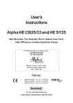
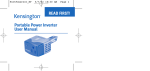
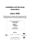
User's
Instructions
Alpha CD18S/24S/30S
Wall Mounted, Fan Assisted, Room Sealed, Gas Fired,
High Efficiency Condensing System Boiler
For Technical help or for Service call ...
ALPHA HELPLINE
Tel: 0870 3001964
Nepicar House, London Road,
Wrotham Heath, Sevenoaks,
Kent TN15 7RS
*HEJEID/=I
Service Listed
Alpha CD18S
Alpha CD24S
Alpha CD30S
G.C. No. 41 532 06
G.C. No. 41 532 02
G.C. No. 41 532 08
For use with Natural Gas only
Leave these instructions with the User
1
DESCRIPTION
The Alpha CD18S, 24S and 30S are high efficiency condensing wall mounted, fan assisted room-sealed system boilers.
The boilers are system boilers providing heating only for sealed central heating systems.
The CD18S boiler is suitable for central heating loads of between 4.7 and 19.5 kW (16 050 and 66 500 Btu/h).
The CD24S boiler is suitable for central heating loads of between 4.7 and 25.4 kW (16 050 and 86 700 Btu/h).
The CD30S boiler is suitable for central heating loads of between 6.5 and 29.8 kW (22 200 and 101 700 Btu/h).
The boilers will provide central heating (as required) during the 'on' times set on your clock (if fitted).
The burner is lit electronically.
2
USER CONTROLS
Fig. 1
3
BOILER CONTROLS
1. CENTRAL HEATING THERMOSTAT
This thermostat controls the temperature of the water leaving the boiler for the heating system. For maximum efficiency from the
boiler the thermostat should be left at number 5 or 6 as shown in Fig. 1. If lower heating temperatures are required, turn the thermostat
anti-clockwise. If higher temperatures are required, turn the thermostat clockwise.
2. SELECTOR SWITCH
This control is used to turn the boiler on and off or to 'reset' the ignition sequence or to set to frost thermostat only. The internal
clock (if fitted) and frost thermostat will not operate when the switch is in the vertical position, i.e. 'Off' position (0).
3. PRESSURE GAUGE
This indicates the central heating system pressure. It should always be within the green band when cold, increasing slightly
when hot.
If the pressure falls below the green band, i.e. lower red area, the system needs re-pressurising. Contact your Installer to have
the system checked and pressurised.
2
Alpha CD18S/24S/30S
4. INDICATOR NEONS
When neons A (red), B (red), C (yellow), D (green) are illuminated, the following conditions apply:Neon
D
Illuminated continuously - Electricity supply to the boiler is on.
C
Illuminated continuously - Burner is alight.
A
Flashing on and off - Temperature sensor fault, contact your Service Engineer.
B
Flashing on and off - Overheat thermostat has operated. Rotate selector switch to the reset position (3) to reset. If this continues
to happen, contact your Service Engineer.
B
Illuminated continuously - Burner has failed to light. Rotate selector switch to the reset position (3) and the ignition
sequence will restart after a delay of about 30 seconds.
A and B Flashing on and off at the same time - Blocked flue or fan fault, contact your Service Engineer.
A and B Flashing on and off alternately - System pressure is very low and re-pressurisation is required.
A Flashing and B Illuminated continuously - Pump fault or restricted flow.
Note: Do not hold the selector switch in the reset position (3) for more than 2 or 3 seconds.
5. OVERHEAT THERMOSTAT
This thermostat automatically switches the boiler off in the unlikely event of the boiler overheating. When the thermostat operates,
the red neon (B) flashes on and off. Rotate the selector switch to the reset position (3) and the boiler will relight.
If this continually happens, contact your Service Engineer.
6. PRESSURE RELIEF VALVE
If the central heating system overheats and steam or water is discharged from the pipe connected to this valve, turn the boiler off
and contact your Service Engineer. Your Installer should have shown you where this pipe terminates, usually outside your dwelling.
7. FROST THERMOSTAT
The boiler has a built-in frost thermostat, which automatically operates the boiler if the water temperature falls below 8°C,
providing the electrical supply is on and the selector switch is set to position (1) or position (2).
4
LIGHTING INSTRUCTIONS
Refer to Fig. 1 for boiler controls.
1.
Ensure the following:a. Electrical supply to the boiler is off.
b. All heating controls and thermostats are set to OFF or minimum position.
c. All isolation valves at the bottom of the boiler are in the open position (slot on the spindle in line with the valves i.e.
).
d. The gas and water supplies are on at the mains.
e. The heating system pressure is within the green band as shown by the pressure gauge.
2.
Switch on the electrical supply to the boiler.
3.
Set any room thermostats to maximum and ensure that any clock is in an 'on' position.
4.
Set the selector switch to position (2) and turn the heating thermostat fully clockwise. The main burner will light and the
boiler will provide central heating.
5.
Set the boiler thermostats, clock, external controls i.e. room thermostat to your chosen settings and the boiler is ready to operate.
To turn the central heating off i.e. in Summer:- Set the selector switch to position (1).
To turn the boiler off for short periods:- Set the selector switch to position (1).
Note: In this position the pump will automatically operate for 5 minutes in every 24 hours. If the water temperature falls below
8°C the built-in frost thermostat will operate the boiler automatically until the temperature of the water in the heating system has
been raised.
To turn the boiler off for longer periods:- Switch off the electrical supply to the boiler. If required, all supplies i.e. gas, water
and electricity may be turned off at the mains. If there is any possibility of the boiler being left during frost conditions, then the
boiler and system should be drained and a label attached to the boiler drawing attention that the system has been drained. If
this is required, contact your Service Engineer.
Alpha CD18S/24S/30S
3
5
BOILER OPERATION
The operating sequence of the boiler is controlled by the selector switch on the control panel.
Setting the selector switch to position (2) the boiler will operate to provide central heating.
When the selector is set to central heating, it will respond to a demand for heat in the following sequence:a. The pump will start, the fan will operate and the main burner will light.
b. The output of the burner is automatically controlled to suit the system demand.
c. When the temperature of the system water in the boiler reaches that set by the thermostat or the room thermostat is
satisfied, the main burner is turned off and the fan stops after 50 seconds. The pump will continue to run to remove any
residual heat from the boiler.
6
IMPORTANT NOTES
1. BOILER LOCATION
Always ensure the following clearances are available around the casing of the boiler (not including the bottom tray):Top: 220 mm, Bottom: 250 mm, Each side: 5 mm, Front: 450 mm
Do not store any other articles in the cupboard containing the boiler and never place any clothing or combustible material on or near
the boiler or flue pipe.
2. FLUE TERMINAL
The terminal on the outside wall must not be allowed to be obstructed. If it is damaged, in any way, turn the boiler off and
contact your Service Engineer.
Note: The Alpha CD boilers are high efficiency condensing boilers and when operating vapour will be emitted from the
terminal. This is safe and quite normal.
3. MAINS FAILURE
In the event of an electrical supply failure the boiler will not operate. When the supply is restored, the boiler will return to normal
operation. Remember to reset the clock, if fitted, when the supply is restored.
4. CLEANING
Use only a damp cloth and mild detergent to clean the boiler outer casing. Do not use abrasive cleaners.
5. SERVICING
To maintain efficient and safe operation of your boiler, routine annual servicing is essential.
For advice on servicing contact:- The Alpha Helpline: 0870 3001964.
6. GAS LEAK
If a fault or gas leak is suspected, turn off the gas supply. Do not touch any electrical switches, do not smoke and extinguish all
naked flames. Contact your local Gas Region immediately.
7. ELECTRICAL SUPPLY
The boiler requires a 230/240 V ~ 50 Hz supply, fused at 3 A if a 13 A 3-pin plug is used or a 5 A fuse if any other type of plug is used.
To connect a plug:The colour of the wires in the mains lead of the boiler may not correspond with the coloured markings identifying the terminals
in your plug. In this case proceed as follows:The wire coloured green and yellow must be connected to the terminal in the plug that is marked with the letter E, or by the
, or coloured green or green and yellow.
earth symbol
The blue wire must be connected to the terminal which is marked with either the letter N or coloured black.
The brown wire must be connected to the terminal which is marked with the letter L or coloured red.
THE APPLIANCE MUST BE EARTHED.
4
Alpha CD18S/24S/30S
7
GAS SAFETY REGULATIONS
Current Gas Safety (Installation and Use) Regulations:It is the law that all gas appliances are installed and serviced by a competent person, i.e. CORGI registered personnel. Failure
to install or service appliances correctly could lead to prosecution. It is in your interest and that of safety to ensure compliance
with the law. The manufacturer's instructions must not be taken in any way as over-riding statutory obligations.
The Benchmark Checklist must be fully completed by the installer on installation and commisioning of the boiler. The
Benchmark Checklist is shown in Section 12 of the Installation and Servicing instructions. All CORGI registered installers carry
a CORGI ID card and have a registration number. Both should be recorded in the Checklist. You can check your installer is
CORGI registered by calling CORGI on 01256 372300.
8
FAULT FINDING FOR THE USER
If you experience a problem of no heating and, if applicable, no hot water, try to solve the problem by following the simple
checks below before calling out a service engineer.
Alpha CD18S/24S/30S
5
6
Alpha CD18S/24S/30S
Alpha CD18S/24S/30S
7
Alpha Therm Limited.
Nepicar House, London Road, Wrotham Heath,
Sevenoaks, Kent TN15 7RS
Tel: 0870 3001964
These instructions have been carefully prepared but we reserve the right to
alter the specification at any time in the interest of product improvement.
© Alpha Therm Limited 2005.
email: [email protected]
website: www.alpha-boilers.com
Manual compiled and designed by Publications 2000 - Tel: (01670) 356211
Part No. 1.023383 Rev. 15.021102/000
08/05/D190