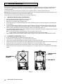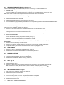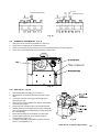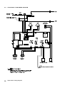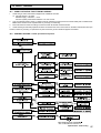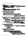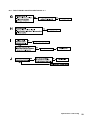
1
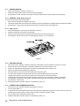
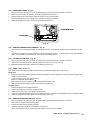
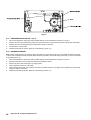
Installation and Servicing
Instructions
Alpha SY9-24
Wall Mounted, Fan Assisted, Room Sealed, Gas Fired
System Boiler
For Technical help or for Service call ...
ALPHA HELPLINE
Tel: 0870 3001 964
Nepicar House, London Road,
Wrotham Heath, Sevenoaks,
Kent TN15 7RS
Service Listed
Alpha SY9-24
G.C. No. 41 532 01
For use with Natural Gas only
Leave these instructions with the User
CONTENTS
1
2
3
4
5
6
Introduction ....................................... 2
Technical data ................................... 3
General boiler information .................. 6
Installation ......................................... 10
Commissioning ................................. 15
Boiler operation ................................. 17
1
7
8
9
10
11
12
Routine servicing ............................... 18
Component replacement ................... 19
Wiring diagrams ................................ 25
Fault finding ...................................... 27
Short parts list ................................... 30
Service history .................................. 31
INTRODUCTION
The Alpha SY9-24 boiler is a wall mounted, fan assisted room-sealed system boiler. The burner is lit electronically and the
heat output is controlled by a modulating gas valve.
The boiler, provides central heating, and is designed for use with a fully pumped, sealed and pressurised heating system using
only Natural Gas.
The boiler is supplied with a pump, pressure relief valve, expansion vessel and pressure gauge fully assembled and tested.
As supplied, the Alpha SY9-24 boiler will automatically modulate to provide central heating outputs between 9.3 and 23.3 kW
(31 700 and 79 500 Btu/h).
IMPORTANT
It is the law that all gas appliances are installed by a competent person, ie CORGI registered personnel, in accordance with
the following recommendations:Current Gas Safety (Installation and Use) Regulations
All current Building Regulations issued by the Department of the Environment i.e. Approved Document L1
Building Standards (Scotland) (Consolidation) Regulations issued by the Scottish Development Department
Health & Safety Document No. 635 (The Electricity At Work Regulations 1989)
The installation should also be in accordance with the following British Standard Codes of Practice:BS 5440:1:2000
BS 5449:1990
BS 6798:2000
BS 6891:1989
BS 7593:1992
BS 7671:2001
Flues
Forced circulation hot water systems
Installation of gas fired hot water boilers
Gas installation
Code of Practice for treatment of water in heating systems
Requirements for electrical installations, IEE Wiring Regulations
If installation is in a timber framed building, refer to the Institute of Gas Engineers document IGE/UP/7.
This appliance meets the requirements of IPX4D, ie degree of protection against moisture.
Failure to install this appliance correctly could lead to prosecution. It is in your own interest and that of safety to ensure that the
law is complied with.
Manufacturer's instructions must NOT be taken in anyway as over-riding statutory obligations.
Note: Ensure that the Benchmark Log Book has been completed after the boiler has been installed and commissioned.
2
Alpha SY9-24 - Contents/Introduction
2
2.1
TECHNICAL DATA
PERFORMANCE - NATURAL GAS
Central Heating
MAX.
MIN.
Heat Input
(Gross)
kW
Btu/h
28.4
96 900
12.1
41 300
Heat Output (modulating)
kW
Btu/h
23.3
79 500
9.3
31 700
Burner Pressure
mbar
in wg
10.7
4.28
2.2
0.9
m³/h
ft³/h
2.71
95.70
1.16
40.96
Settings
Room sealed chamber
panel fitted
Gas Rate
2.2
SYSTEM
Central Heating (Sealed System)
Max. Working System Pressure
2.5 bar
Min. System Pressure
Max. System temperature
0.5 bar
82°C
Pressure Relief Valve Setting
3 bar (44 PSI)
Expansion Vessel Size (pre-charge press.) 8 L at 0.8 bar
Flow Connection
Return Connection
22 mm
22 mm
Relief Valve Connection
Recommended System Pressure (cold)
15 mm
1.0 bar
CH Water Temp. (Approx. max.)
2.3
82°C (180°F)
COMPONENTS
Burner
Stainless steel
Main Heat exchanger
Main Burner Injectors
Copper
1.30 mm (x12)
Flue - Outer Duct
Flue - Inner Duct
2.4
White
Aluminium
INSTALLATION
Min. Clearances for Servicing
(from casing)
Top
Bottom
220 mm
250 mm
Sides
Front
5 mm
450 mm
Flue Terminal Size
Flue Terminal Protruding
100 mm Dia.
145 mm
Hole Size Required For Flue Assy.
Lift Weight
110 mm Dia.
38 kg
Alpha SY9-24 - Technical Data
3
2.5
GENERAL
2.6
ELECTRICAL
Case Dimensions
Height
720 mm
Supply
(without bottom tray)
Width
Depth
450 mm
330 mm
External Fuse
Power Consumption
3A
170 W
Gas Connection
Primary Water Content
22 mm
1.6 L
Internal Fuse
Electrode Spark Gap
F2 A
2 to 4 mm
Air Duct Diameter
Flue Duct Diameter
100 mm
60 mm
2.7
230/240 V ~ 50 Hz
FLUE LENGTHS
Flue length = 0.75 m (not including the terminal, which is supplied with the boiler)
Note: Additional flues (of the same length) are available.
Length of Flue Required:Rear Flue = wall thickness + 175 mm
Side Flue = wall thickness + distance between wall and side of boiler + 185 mm
Vertical Flue = distance from top of boiler side panel to required roof position minus 1 m for vertical terminal assembly
Maximum flue length = 4 m
Each additional 90° Bend is equivalent to 1 m of flue length
Each 45° Bend is equivalent to 0.5 m of flue length
The Vertical Flue terminal assembly is equivalent to 1 m of flue length
2.8
AVAILABLE PUMP HEAD FOR CENTRAL HEATING
Output
kW
Btu/h
Pressure loss across boiler
Flow rate
Available pump head
17°C
17°C
20°C
metres
feet
metres
feet
20°C
litre/min gal/min litre/min gal/min metres
20°C
feet
metres
feet
23.3
79 500
2.4
7.9
3.2
10.5
19.6
4.3
16.7
3.7
2.5
8.2
2.3
7.5
17.58
60 000
3.8
12.5
4.4
14.4
14.8
3.3
12.6
2.8
1.9
6.2
1.3
4.3
14.65
50 000
4.5
14.8
4.8
15.8
12.3
2.7
10.5
2.3
1.25
4.1
0.95
3.1
11.63
40 000
5.1
16.7
5.35
17.5
9.8
2.2
8.3
1.8
0.8
2.6
0.65
2.1
9.3
31 700
5.45
17.9
5.65
18.5
7.8
1.7
6.7
1.5
0.5
1.6
0.4
1.3
This information is based on 17°C and 20°C system design temperature difference.
2.9
ELECTRICAL CONNECTIONS
Note: This Appliance Must Be Earthed
Fig. 1 - Boiler terminal block
4
17°C
Alpha SY9-24 - Technical Data
2.10 BOILER SCHEMATIC
1
-
Gas valve
12
-
Pump
2
-
Primary temperature sensor
13
-
Drain point
3
-
Main burner
14
-
Pressure relief valve
4
-
Main heat exchanger
15
-
Ignition electrodes
5
-
Room sealed chamber
16
-
Flame sensing electrode
6
-
Fan
17
-
Flue sampling point
7
-
Air pressure switch
18
-
Gas service cock
8
-
Flue hood
19
-
Primary pressure switch
9
-
Overheat thermostat
20
-
On/off valve (2 off)
10
-
Expansion vessel
21
-
Automatic by-pass
11
-
Automatic air vent
Fig. 2
Alpha SY9-24 - Technical Data
5
3
3.1
GENERAL BOILER INFORMATION
GAS SUPPLY
The Alpha SY24 boiler requires a gas rate of 2.71 m³/h (95.7 ft³/h).
The meter and supply pipes must be capable of delivering this quantity of gas in addition to the demand from any other
appliances in the house. The boiler requires at least a 22 mm gas supply pipe.
The complete installation, including the meter, must be tested for gas soundness and purged as described in BS 6891.
3.2
ELECTRICAL SUPPLY
The boiler requires a 230/240 V ~ 50 Hz mains supply, fused at 3 A
The boiler must be earthed.
There must only be one common isolator, providing complete electrical isolation, for the boiler and any external controls.
This boiler has been fitted with a supply cable, however, if it is necessary to fit a cable use PVC insulated cable not less than
0.75 mm² (24 x 0.2 mm) to BS 6500 Table 16. The boiler should be connected to a fused three pin plug and unswitched
shuttered socket outlet (both complying with BS 1363), or a fused double pole switch with a contact separation of at least 3 mm
in both poles.
Wiring external to the boiler must be in accordance with the current IEE Wiring Regulations (BS 7671).
Note: If a room thermostat is fitted, it must be suitable for 230/240 V switching.
3.3
AIR SUPPLY
The boiler does not require any air vents for cooling in the room in which it is installed or when installed in a cupboard or
compartment. The minimum clearances for servicing must always be maintained.
Note: A cupboard or compartment used to enclose the boiler must be designed and constructed specifically for the purpose,
i.e. comply with the Building Regulations.
3.4
FLUE SYSTEM - Fig. 3
The flue system must be installed in accordance with BS 5440:1.
For horizontal flues ensure there is a slight downward slope towards the terminal.
Flue components are available as follows:Top easy-flue 500 mm (includes 90° bend), refer to separate instructions
0.75 m flue
90° bend
45° bend
Vertical flue terminal assembly. Refer to the separate installation instructions supplied with the assembly.
A Twin Pipe Flue system is available for use with all the boilers in the range. Refer to the separate instructions for details.
The following methods determine the correct length of flue required.
For rear exit flue L = B + 175 mm
For side exit flue L = B + C + 185 mm (min. side clearance required is 5 mm)
For vertical flue L = H minus 1000 mm for vertical terminal assembly
Where
L = Required flue length
B = Finished wall thickness
C = Distance from the inside wall to the side of the boiler
H = Distance from top of boiler side panel to roof position
Note: 1. If an extra 90° bend is used, this reduces the maximum flue length by 1 m. Each 45° bend used reduces the maximum
flue length by 500 mm.
2. Under no circumstances must the flue length (including allowances for extra bends) exceed 4 metres.
3. Failure to use Alpha flue components with the boiler will invalidate the boilers CE approval, guarantee and may be unsafe.
6
Alpha SY9-24 - General Boiler Information
HORIZONTAL FLUE OPTIONS - Lmax = 4 metres
L = B + C + 185 mm
L = B + C + E + 185 mm
B
C
B
C
E
B
F
E
C
L = B + E + F + 185 mm + (90° bend = 1 metre)
B
L = B + C + 185 mm + (2 x 45° bends = 1 metre)
VERTICAL FLUE OPTIONS
Fig. 3
Alpha SY9-24 - General Boiler Information
7
3.5
FLUE TERMINAL LOCATION - Fig. 4
Fig. 4
Terminal position
Min. distance
A
Directly below an opening, air brick, windows, etc.
300 mm
B
C
Below gutters, soil pipes or drain pipes
Below eaves
75 mm
25 mm
D
Below balconies or car port roof
25 mm
E
From a vertical drain pipe or soil pipe
25 mm
F
From an internal or external corner
25 mm
G Above ground, roof or balcony level
300 mm
H
I
From a surface facing the terminal
From a terminal facing the terminal
600 mm
1200 mm
J
From an opening in the car port (e.g. door, window) into dwelling
1200 mm
K
Vertically from a terminal on the same wall
1500 mm
L
Horizontally from a terminal on the same wall
300 mm
M Horizontally from an opening, air brick, window, etc.
300 mm
The flue terminal must be exposed to the external air and the position must allow the free passage of air across it at all times.
In certain weather conditions the terminal may emit a plume of steam. Avoid positioning the terminal where this may cause a nuisance.
If the terminal is fitted within 850 mm of a plastic or painted gutter or 450 mm of painted eaves or 300 mm of a plastic car port
roof, an aluminium shield at least 1 m long should be fitted to the underside of the gutter or painted surface. If the terminal is
fitted less than 2 m above a surface to which people have access, the terminal must be protected by a terminal guard.
A suitable guard is available from:
Tower Flue Components Ltd., Vale Rise, Tonbridge, Kent TN9 1TB
3.6
BOILER LOCATION
The boiler is not suitable for external installation.
The boiler must be installed on a flat vertical wall which is capable of supporting the weight of the boiler. The boiler can be fitted
to or adjacent to a wall comprising of a combustible material without the need for a special thermal insulation barrier.
If the boiler is to be fitted in a timber framed building, it should be fitted in accordance with the British Gas publication 'Guide for
Gas Installations in Timber Frame Housing', reference DM2.
The boiler may be installed in any room or internal space, although particular attention is drawn to the requirements of the
current IEE Wiring (BS7671) Regulations, and in Scotland, the electrical provisions of the Building Regulations applicable in
Scotland, with respect to the installation of the boiler in a room or internal space containing a bath or shower. Where a roomsealed boiler is installed in a room containing a bath or shower, it must not be possible for a person using the bath or shower
to touch any electrical switch or boiler control utilising mains electricity.
The boiler may be installed in a cupboard or compartment, provided it is correctly designed for that purpose, i.e. complies with
the Building Regulations and the requirements of BS 6798.
8
Alpha SY9-24 - General Boiler Information
3.7
CENTRAL HEATING SYSTEM - Fig. 5
The boiler is designed for use in a sealed central heating system in accordance with the requirements of BS 5449 and BS 6798.
The system should be designed to operate with flow temperatures of up to 82°C. When designing the system, the pump head, expansion
vessel size, mean radiator temperature, etc must all be taken into account. Refer to the pump performance table for guidelines.
System volume - The expansion vessel incorporated into the boiler is suitable for a sealed heating system with a maximum
water content of 80 litres (18 gal). For guidance on water contents contact Alpha Therm Ltd. for Technical Data Sheet 15.
Above 80 litres, consideration should be given to fitting an additional expansion vessel fitted in the position shown in Fig. 5. To
check correct operation of the expansion vessel(s) the system pressure should not be more than 2.5 bar when the system is at
maximum operating temperature (for further guidance refer to BS 7074:1).
The boiler is supplied with the following components built in:Pressure relief valve - complying with BS 6759 and set to operate at 3 bar. The discharge pipe must be routed clear of the
boiler, in such a manner that it can be seen, but cannot cause injury to persons or property.
Pressure gauge - To indicate the system pressure to be maintained.
Expansion vessel - Conforming to BS 4814 with a capacity of 8 litres and pre-charged to a pressure of 0.8 bar.
By-pass - The boiler incorporates a by-pass. However, where all radiators are fitted with thermostatic radiator valves it is
recommended a system by-pass, preferably automatic, is fitted.
Make up vessel
Static head of system
Boiler
casing
Automatic
air vent
Additional expansion
vessel (if required)
Double check valve assy.
Heating
by-pass
(If required)
Note: If required, an automatic by-pass is
preferred.
Filling point
Heating flow
Heating return
Note: A drain tap should be installed at the lowest
point of the heating circuit and beneath the appliance.
System
drain tap
Fig. 5
3.8
FILLING THE CENTRAL HEATING SYSTEM - Figs. 6, 7
The system design pressure (cold) should be set to 1.0 bar. This pressure is equivalent to a static head (see Fig. 5) of 10.2 metres of water.
Provision should be made to replace water lost from the system. This can be by manual or automatic means, as shown in Figs.
6 and 7. The position for connecting an automatic make-up vessel is indicated in Fig. 5. A double check valve assembly must
be used, as shown in Fig. 7.
Filling of the system must be carried out in a manner approved by the local Water Undertaking. Where allowed, the system may
be filled via a temporary connection as shown in Fig. 6. After filling, always disconnect the flexible hose of the filling loop.
All fittings used in the system must be able to withstand pressures up to 3 bar.
Drain taps (to BS 2879) must be used to allow the system to be completely drained.
The heating system should be thoroughly flushed before the boiler is connected and again after the first heating.
If it is required to add inhibitor to the system, refer to Alpha Therm Ltd. for guidance.
Refer to BS 5449 and BS 6798 for further information.
Overflow
Hose
unions
Heating circuit
return
Double check
valve assembly
Stop
valve
Stop
valve
Test cock
Mains
water
supply
Heating circuit
return
Mains
water
supply
Double check
valve assembly
Test cock
Stop
valve
Feed cistern to be
located above highest
point in the system
Filling loop
temporarily connected
Fig. 6
Fig. 7
Alpha SY9-24 - General Boiler Information
9
4
4.1
1.
INSTALLATION
UNPACKING
The boxes required when the boiler is installed with a horizontal flue are as follows:Box 1
Cased boiler fitted with water and gas valves, union bends and washers
Mounting bracket plus screws and wall plugs
Flue terminal and flue sealing collar plus 2 screws
Literature pack and Wall template
Box 2
90° flue bend (not required for vertical flue)
Box 3
0.75 m flue (for side and rear flue) with two clamps and inner duct support
Note: If an Easy flue 500 mm is ordered, this will be supplied instead of boxes 2 and 3.
2.
Unpack boiler and remove the loose items packs, i.e. mounting bracket, flue terminal and collar.
Note: The boiler can be stood in an upright position supported by the bottom tray, (to allow this, the union bends have
been turned upwards so that they do not protrude beneath the bottom tray - check this before standing the boiler on the
bottom tray).
4.2
CLEARANCES REQUIRED - Fig. 8
Fig. 8
4.3
PREPARE THE WALL - Figs. 9, 10
1.
Decide upon the position of the boiler taking into
account the clearances required for servicing and
the flue terminal position.
2.
Tape the template to the wall (ensure it is level and
the right way up) and mark the position of the holes
for the boiler mounting bracket and bottom fixings. If
rear exit flue is used, mark the position of the hole
for the flue.
3.
Side exit flue - Continue the horizontal centre line of
the flue across the wall to the side wall, then along the
side wall 215 mm (ensure the lines are horizontal). This
will give the position of the centre of the hole for the flue.
4.
Cut the 110 mm diameter hole (or use a 107 mm
core drill) in the wall for the flue.
Note: For internal fitting of the flue, using the flue
sealing collar supplied, cut a 127 mm dia. flue hole
using a 127 mm core drill.
5.
Drill the fixing holes (10 mm dia.) to accept the No.10
plugs supplied. Using the screws supplied, fit the
mounting bracket.
6.
Top pipe connections - Preform the pipework at the back of the boiler before hanging the boiler, see Fig. 10, and secure in
the clips provided.
10
Alpha SY9-24 - Installation
Fig. 9
4.4
FIT THE BOILER - Refer to Fig. 10
1.
Lift the boiler and locate it on the mounting bracket.
2.
Fit the bottom screws to secure the boiler in position.
Fig. 10
4.5
CONNECT THE PIPEWORK - Fig. 11
1.
Thoroughly flush out all the water pipework.
2.
The valves/fittings have been factory fitted, however, check that all the connections underneath the boiler have been
tightened, especially the union bends.
To gain access to all the connections remove the bottom tray by removing the four fixing screws. When all the connections
have been checked for soundness replace the tray and secure with the four screws previously removed.
The heating union bends have been designed to enable the heating pipes to be routed from above and/or below using the
same fitting.
Note: When soldering to the boiler union bends, ensure the bends are not connected to the valves, otherwise the internal
seals may be damaged.
3.
Connect the system pipework to the boiler.
Note: Do not forget that the pressure relief valve discharge pipe must be routed clear of the boiler to a drain in such a
manner that it may be seen, but cannot cause injury to persons or property.
4.
Ensure that all the valves are closed (spindle flats at right angles to valve) and do not turn on the water or gas supplies at this stage.
E
A - Heating flow (22 mm)
B - Heating return (22 mm)
C - Gas inlet (22 mm)
D - Pressure relief valve (15 mm)
E - Heating drain point
23
70
212.5
C
47.5
D
70
B
50
A
Fig. 11
Alpha SY9-24 - Installation
11
4.6
1.
FIT THE FLUE - Figs. 12, 13
The following procedure applies to both rear or side exit flue. The only difference being the lengths to which the ducts are cut.
Rear flue Outer air duct length = finished wall thickness + 135 mm.
Inner flue duct length = finished wall thickness + 172 mm.
Side flue Outer air duct length = finished wall thickness + the distance from the inside wall to the side of the boiler + 145 mm.
Inner flue duct length = finished wall thickness + the distance from the inside wall to the side of the boiler + 182 mm.
2.
If the overall length of the inner duct is greater than 750 mm then a flue extension is required. To fit an extension refer to
the following section.
3.
Withdraw the inner flue duct from the outer air duct.
4.
Mark the outer air duct to match the length given above, measure from the end of the tube as shown in Figs. 12 and 13.
5.
Mark the inner flue duct to match the length given above.
6.
Cut both the inner and outer ducts to length.
Note: Do not cut the outer duct end with the two holes, these are for securing the terminal.
Ensure that all cuts are square and burr free.
7.
Fit the flue terminal to the outer duct ensuring it is fully located and secure with the two screws provided.
8.
Place the inner flue duct back into the outer duct.
9.
Pass the flue assembly through the wall (from inside or outside).
Note: Internal fitting - If there is no access to make good the outside wall, locate and secure the flue sealing collar onto
the outer duct of the flue immediately before the terminal. Push the flue assembly through the 127 mm flue hole, so that
the collar completely passes through the wall. Then pull the flue assembly back into the correct position. Visually check
that the collar is sealing the outside wall and that it is not restricting any of the openings of the flue terminal.
10. Position the seal and clamp (two screws), supplied with the bend, over the boiler flue adaptor. Fit the bend and rotate to
the correct position, then secure in position. See Fig 12.
Note: Ensure that the seal is located over both the bend and the flue adaptor.
11. Place the inner (no seal) duct clamp in position over the bend outlet as shown in Figs. 12 and 13, and position the outer
duct seal over the bend.
12. Push the outer duct into the wall slightly at the same time as pulling the inner duct towards the bend, inserting it fully into
the clamp on the bend. Tighten the clamp to secure the inner duct.
Note: Ensure the inner duct clamp screwed joint is at the bottom.
13. Pull the outer duct towards the bend. Check that the flue terminal protrudes 130 mm out of the wall, then position the seal
equally over the joint between the bend and the outer duct. Dismantle the clamp, position it over the seal (if applicable)
and secure in position.
14. Make good the inside and outside walls. The flue sealing collar could be used for making good either the outside or inside
by locating it over the outer duct of the flue and pushing it tight against the wall. If fitting the collar externally, ensure it does
not restrict any of the openings of the flue terminal.
Fig. 12 - Rear flue
12
Alpha SY9-24 - Installation
Fig. 13 - Side flue
4.7
FIT A FLUE EXTENSION - Figs. 12, 13
Note: 1. The maximum flue assembly length must not exceed a length of 4 metres.
2. If the flue is more than 1.5 m, the restrictor must be removed from the flue adaptor (see Fig. 13).
1.
Withdraw the inner flue duct from the outer air duct supplied with the boiler.
2.
Withdraw the inner flue duct from the extension. Secure the two ducts together using the clamp supplied with the
extension, ensure that the ducts are butted together and the clamp is central over the joint.
3.
Secure the outer ducts together using the silicone seal (if applicable) and clamp supplied with the extension.
4.
With all the ducts assembled together, cut to the following lengths:Rear flue Outer air duct length = finished wall thickness + 135 mm.
Inner flue duct length = finished wall thickness + 172 mm.
Side flue Outer air duct length = finished wall thickness + the distance from the inside wall to the side of the boiler + 145 mm.
Inner flue duct length = finished wall thickness + the distance from the inside wall to the side of the boiler + 182 mm.
5.
When measuring the outer duct, measure from the end of the tube as shown in Figs. 12 and 13.
6.
Cut both the inner and outer ducts to length. Ensure that all cuts are square and burr free.
7.
Fit the flue terminal to the outer duct ensuring it is fully located and secure with the two screws provided.
8.
Place the inner flue duct back into the outer duct. Use the inner duct supports to centralise the duct in the outer duct.
9.
Fit the flue assembly as described in the previous section. Due to the size of the flue clamps the flue must be fitted from
inside the building.
10. It may be necessary to support the flue with suitable brackets (every metre) when flue lengths approaching the maximum
are used.
Alpha SY9-24 - Installation
13
4.8
CONNECT THE MAINS SUPPLY - Fig. 14
1.
Gain access to the boiler terminal block by releasing the
two fixing screws (one each side) securing the control
panel and lowering the panel. Refer to Technical Data,
section 2.9 for connection details.
2.
Note: This boiler has been fitted with a mains supply
cable. However, if it is necessary to fit an alternative
supply cable, ensure the cable clamp that has been
fitted is removed and connect as follows:Remove the two screws securing the terminal block
cover from the back of the control box (see Fig. 14).
Pass the mains supply cable through the cable clamp
and connect as follows:- Brown to L, Blue to N and
Green/Yellow to
. Ensure correct polarity.
Note: Ensure that the length of the earth wire is such
that if the supply cable is pulled out of its clamp the live
and neutral wires become taut before the earth wire.
The main terminal block can be removed by pulling it
off the pins to give easy access to the terminals.
Do not switch on the electrical supply at this stage.
Fig. 14
3.
If an external control, i.e. room thermostat or external clock is to be fitted, remove the terminal block cover and remove the
link between terminals 1 and 2. Pass the cable through the cable clamp and connect it to terminals 1 and 2. Replace the
terminal block cover. (Refer to section 2.9).
4.
Replace the terminal block, ensuring it is located correctly on the plastic pins and replace the cover.
5.
Ensure that there is sufficient free cable to allow the control panel to be raised and lowered then tighten the cable clamp screws.
6.
Leave the control panel open until commissioning procedures have been completed.
7.
Carry out electrical system checks - Short circuit, Polarity, Earth continuity and Resistance to earth with a suitable multimeter.
14
Alpha SY9-24 - Installation
5
COMMISSIONING
When commissioning the boiler, ensure the Benchmark Log Book is completed.
5.1
FILL THE SYSTEM
1.
The boiler is fitted with an automatic air vent positioned on the pump (see Fig. 2). The vent is always open and has no
sealing cap.
2.
Open the central heating flow and return valves (slot in-line with valve) (see Fig. 11).
3.
Open the fill point valve on the filling loop until water is heard to flow. To aid venting, the boiler drain point (see Fig. 2) may
be opened until water flows out. Close the drain point as soon as water appears.
4.
To remove the air - Vent each radiator in turn, starting with the lowest in the system.
5.
It is important that the pump is properly vented to avoid it running dry and damaging its bearings. Unscrew and remove the cap
from the centre of the pump. Using a suitable screwdriver rotate the exposed spindle about half a turn, then replace the cap.
6.
Check the operation of the pressure relief valve (see Fig. 2) by turning the head anti-clockwise until it clicks. The click is
the valve lifting off its seat allowing water to escape from the system - check that this is actually happening.
7.
Continue to fill the system until the pressure gauge indicates 1.0 bar. Close the fill point valve and check the system for
water soundness, rectifying where necessary. Disconnect the filling loop from the mains supply.
Water may be released from the system by manually operating the drain point (see Fig. 2) until the system design
pressure is obtained. The system design pressure (cold) should be between 0.75 and 1.25 bar.
Refer to sections 3.7 and 3.8. System volume and Filling the system.
5.2
BOILER CONTROLS - Fig. 15
Fig. 15
5.3
TEST FOR GAS SOUNDNESS AND PURGE THE SUPPLY
1.
With the boiler gas service cock closed (slot at right angles to valve). Pressure test the gas supply and inlet pipework
connection to the boiler gas service cock for soundness in accordance with BS 6891.
2.
Loosen the gas inlet pressure test point screw on the gas valve (see Fig. 16). Ensure the gas supply is on and open the
boiler service cock to purge in accordance with BS 6891.
3.
Retighten the test point screw and test for gas soundness. Close the boiler gas service cock.
5.4
INITIAL LIGHTING - Refer to Fig. 15
1.
Ensure that the gas and electrical supplies to the boiler are off and that the central heating flow and return valves are open.
2.
Turn on the gas and electrical supplies to the boiler.
3.
Ensure all external controls are calling for heat. If the optional Clock is fitted, refer to the User's instructions, set the time
and ensure the Clock is in an 'on' mode.
4.
Set the central heating temperature selector to maximum.
5.
Set the selector switch to ON. The pump will start, the fan will start; once the pressure switch is proved, the main gas valve
solenoid will open allowing the main burner to light from the ignition electrodes.
Alpha SY9-24 - Commissioning
15
5.5
CHECK THE BURNER PRESSURES - Fig. 16
Set the central heating selector to 0 to turn the boiler off. Loosen the
burner pressure test point screw on the gas valve and connect a
pressure gauge. Allow the boiler to run for 10 minutes and check the
burner pressures.
1.
Set the selector switch to ON.
2.
The burner will light at the ignition rate and will increase to the
factory pre-set maximum output.
Note: The burner pressure settings have been factory set and do
not require adjusting. If incorrect, check that the inlet gas pressure
is 20 mbar. If the inlet gas pressure is not 20 mbar, either the
pipework is too small or the gas supply to the house is insufficient,
in which case contact your gas supplier.
3.
Turn off the boiler. Disconnect the pressure gauge and tighten the
test point screw.
Fig. 16
Test for gas soundness using suitable leak detection fluid.
Note: Refer to Technical Data, section 2.1 for burner pressure settings.
5.6
1.
2.
3.
4.
5.7
1.
2.
3.
4.
5.
5.8
FINAL COMMISSIONING
Allow the heating system to heat up, then balance the system to achieve the necessary temperature difference across the
heating flow and return pipes at the boiler and check the system volume and pressure. (Refer to Technical Data, sections
2.2 and 2.8).
Turn off the boiler.
Thoroughly flush out the water pipework.
Re-pressurise the system as described in section 5.1.
FINAL ASSEMBLY
Raise the control panel and secure in position with the screws provided.
If the boiler is to be left in service with the User, set the controls, clock (if fitted, see User's Operating manual) and room
thermostat (if fitted) to the User's requirements.
If the boiler is not to be handed over immediately, close the boiler gas service cock and switch off the electrical supply.
If there is any possibility of the boiler being left during frost conditions, then the boiler and system should be drained (refer to section
8.2). It is recommended that a label is attached to the boiler drawing attention to the fact that the system has been drained.
Complete the details of the installation on the back page of this manual and the Benchmark log book.
USER INFORMATION
The User must be advised (and demonstrated if necessary) of the following important points:1. How to light and turn off the boiler and how to operate the system controls.
2. The importance of annual servicing of the boiler to ensure safe and efficient operation.
3. That any servicing or replacement of parts must only be carried out by CORGI registered personnel.
4. Ensure that the boiler controls and room thermostat (if fitted) are set to the User's requirements.
5. Tell the User about the sealed system pressure.
6. Tell the User that if the electrical supply is on and the boiler has not operated for 24 hours, the pump will automatically
operate for 5 minutes.
7. Explain to the User that an internal frost thermostat is fitted in the boiler, and that the electrical supply to the boiler must be
left on and the selector switch set to
for the thermostat to operate.
8. Show the User the position of the pressure relief valve discharge pipe.
9. Hand the User's instructions and the Benchmark Log Book to the User.
10. Leave these Installation and Servicing instructions with the User for use on future calls.
11. Inform the User that the boiler bottom tray has the facility to store the instructions and log book.
16
Alpha SY9-24 - Commissioning
6
BOILER OPERATION
The boiler operation is controlled by the selector switch on the facia panel. When set to ON, it will provide central heating.
6.1
CENTRAL HEATING
If there is a call for heat, the pump will start to circulate the central heating water. The fan will run at full speed; once the air
pressure switch is proved the burner will light. The burner output then automatically adjusts to suit the system demand; as the
temperature of the water in the boiler approaches that set by the adjustable central heating thermostat (see Fig. 15), the burner
output is reduced. When the set temperature is reached, the burner is turned off. The fan continues to run for 20 seconds and
the pump continues to run for three minutes to remove residual heat build up in the boiler before allowing the burner to relight. If
the CH sensor has not registered the pre-set temperature but the room thermostat is satisfied the burner is turned off. The fan
continues to run for 20 seconds and the pump continues to run for 30 seconds. In this instance there is no 3 minute delay
before the burner will relight.
Note: If the system pressure is very low, the primary pressure switch will prevent the boiler from operating.
6.2
FROST THERMOSTAT
The boiler incorporates a built in frost thermostat which automatically turns on the boiler and pump if the water in the boiler falls
below 8°C, providing the electrical supply is on and the selector switch set to . The boiler will operate until the water
temperature in the system reaches approximately 40°C.
6.3
PUMP
If the electrical supply is on and the boiler has not operated for 24 hours, the pump will operate automatically for five minutes
every 24 hours.
6.4
INDICATOR NEONS
When neon A (red) and neon B (yellow) are illuminated, the following conditions apply:Neon
B
Flashing very slowly (every 5 seconds) - Electricity supply to the boiler is on.
B
Illuminated continuously - Indicates the burner is alight.
B
Flashing on and off - Temperature sensor fault.
A
Flashing on and off - Overheat thermostat has operated. Rotate selector switch to the reset position (3) to reset.
A
Illuminated continuously - Burner has failed to light. Rotate the selector switch to the reset position (3) and the
ignition sequence will restart after a delay of about 30 seconds.
A and B Flashing on and off at the same time - Blocked flue or fan fault.
A and B Flashing on and off alternatively - System pressure is very low and re-pressurisation is required.
A Illuminated continuously and B flashing - Pump fault or restricted flow.
Alpha SY9-24 - Boiler Operation
17
7
ROUTINE SERVICING
To ensure efficient operation of the boiler it is recommended that it is checked and serviced as necessary at regular intervals.
The frequency of servicing will depend upon the particular installation conditions and usage, but in general once per year
should be adequate.
It is the law that any service work must be carried out by a competent person, ie CORGI registered personnel.
Warning: Before servicing the boiler, isolate the electrical supply and close the boiler gas service cock. Allow the boiler to cool.
The data label is positioned on the inside of the left hand side panel.
Always test for gas soundness after servicing any gas carrying components.
7.1
IMPORTANT NOTES PRIOR TO SERVICING
1.
Check the flue terminal outside and ensure it is not blocked.
2.
Run the boiler and check the operation of its controls.
3.
Refer to Fig. 2 for location of flue sampling point.
4.
Ensure that all system connections and fittings are sound. Remake any joints and check the tightness of any fittings that
may be leaking.
5.
It is recommended that the operation of the safety valve is checked by turning the head anti-clockwise until it clicks. The
click is the safety valve lifting off its seat allowing water to escape from the system - check that this is actually happening.
6.
Refill, vent and re-pressurise the system as necessary. (Refer to Commissioning, section 5.1).
If the system pressure exceeds 2.5 bar when operating at maximum temperature, the heating expansion vessel should be
checked and re-pressurised, if necessary.
Note: 1. Check the expansion vessel charge only when the system pressure is zero.
2. The expansion vessel pressure test point is accessible from the top and rear of the boiler.
7.
Record details of the service in the Service History section on page 31 of this manual and in the Benchmark Log Book.
7.2
PREPARE FOR SERVICING - Fig. 17
1.
Ensure the electrical supply is isolated and the gas supply is off.
2.
Unscrew the two screws securing the control panel and lower the panel.
3.
Lift the case front panel upwards slightly and pull it forwards to remove it from the boiler.
4.
Remove the four screws securing the room sealed chamber panel and remove the panel, taking care not to damage the seal.
5.
Remove the four screws securing the combustion chamber front cover and remove the cover.
6.
Disconnect the electrode leads from the electrodes and the in-line connector to the flame sensing electrode.
7.
Remove the four screws securing the burner and withdraw it out of the boiler. Take care not to damage the side insulation
panels.
Fig. 17
18
Alpha SY9-24 - Routine Servicing
7.3
CLEANING THE BOILER
1.
Remove any deposits from heat exchanger using a suitable soft brush. Do not use a brush with metallic bristles.
2.
Check the condition of the combustion chamber insulation panels. Any damaged panels must be replaced. (Refer to
Component Replacement, section 8.23).
3.
Check the condition of the burner injectors on the manifold, carefully clean them with a soft brush if necessary.
Do not use a brush with metallic bristles as this might damage the injectors.
4.
Remove any fallen deposits from the bottom of the inner case.
5.
Unscrew and replace any injector that appears damaged.
6.
Clean the top of the burner with a soft brush and check that the flame ports are clear. Blockages may be removed with a
stiffer brush. Tap the burner, open end down, to remove any deposits from inside.
7.
Check the condition of the electrodes.
9.
Check the spark gap, positioning and height of the electrodes (see Fig. 18).
10. Check that the fan impeller is clean and free to rotate.
7.4
RE-ASSEMBLE THE BOILER
1.
Replace the burner, ensuring it is located correctly and secure it in position using the four screws previously removed.
2.
Replace the combustion chamber front cover, ensuring it is correctly located.
3.
Ensure the electrode leads are connected and the seals are in position in the bottom of the inner case.
4.
Test the connections for gas soundness and check the burner pressures. (Refer to Commissioning, sections 5.4 and 5.5).
5.
Ensure that the room sealed chamber panel seal is intact and in position, replace the panel ensuring it has been located
correctly (especially on the sides) and secure it in position with the screws previously removed.
6.
Place the front case panel in position as shown in Fig. 17 and secure in position.
7.
Raise the control panel and secure in position with the two screws provided.
8.
Check the operation of the boiler. (Refer to Boiler Operation, section 6).
9.
Return all controls to their original settings.
8
COMPONENT REPLACEMENT
It is the law that any service work must be carried out by a competent person, ie CORGI registered personnel.
Warning: Before replacing any boiler components, isolate the electrical supply and close the boiler gas service cock. Allow the
boiler to cool.
Always test for gas soundness after replacing any gas carrying components or disturbing any gas connections.
Check the operation of the boiler. (Refer to Boiler Operation, section 6).
Ensure that all the controls are returned to their original settings.
The replacement of components in sections 8.3 to 8.13 does not require draining of the boiler.
8.1
GENERAL ACCESS - Fig. 17
Ensure the electrical supply is isolated and the gas supply is off.
1.
If access is required behind the control panel - Release the two fixing screws (one each side) securing the control panel
and lower the panel.
2.
To gain access behind the casing - Lift the case front panel upwards slightly and pull it forwards to remove it from the boiler
(see Fig. 18). If required, remove the side panels by removing the bottom fixing screw and lifting forwards and upward.
3.
To gain access to the combustion chamber - Remove the four screws securing the room sealed chamber panel and
remove the panel, taking care not to damage the seal.
Note: When replacing the panel, ensure the seal is intact and that the panel has been located correctly, especially on the sides.
4.
To gain access to the control panel components - Remove the five screws securing the rear cover and carefully raise
the cover from the front. When replacing the cover, ensure no wires are trapped and all wiring is secured. Secure with five
screws - do not overtighten.
Alpha SY9-24 - Routine Servicing/Component Replacement
19
8.2
DRAINING THE BOILER - Refer to Figs. 2 or 11
Isolate the electricity supply and close the boiler gas service cock (see Fig. 11). Allow the boiler to cool.
1.
Heating circuit
Close the central heating flow and return valves (see Fig. 11).
Connect a suitable pipe to the drain point (see Fig. 2) and route it to a suitable container. Open the drain point.
Note: Some water will remain in the components and care must be taken when removing them.
8.3
IGNITION ELECTRODE LEAD - Refer to Fig. 21
1.
Gain access to the combustion chamber as in section 8.1.
2.
Disconnect the lead from the electrode.
3.
Disconnect the lead from the PCB, noting its position (see Fig. 21).
4.
Fit the new lead ensuring it passes through the locations in the control panel and grommets in the base of the combustion chamber.
5.
Re-assemble in reverse order.
8.4
ELECTRODES - Fig. 18
Gain access to the combustion chamber as in section 8.1.
1.
Remove the four screws securing the combustion chamber front cover and remove the cover.
2.
Disconnect the leads from the electrodes. Remove the grommet in the bottom of the chamber, disconnect the flame
sensing electrode in-line connector and withdraw the lead.
3.
Withdraw the main burner out of the boiler. Take care not to damage the side insulation panels.
4.
Flame sensing electrode
Remove the screw securing the electrode and withdraw the electrode.
Fit the new electrode, ensuring it is positioned correctly (see Fig. 18).
5.
Ignition electrodes
Remove the screw securing the electrode and withdraw the electrode.
Fit the new electrode, ensuring both are positioned correctly and the spark gap is correct (see Fig. 18).
Re-assemble
1.
Replace the burner, ensuring it is located correctly.
2.
Replace the combustion chamber front cover, ensuring it is correctly located, especially on the sides.
3.
Complete re-assembly as described in Routine Servicing, section 7.4 paragraphs 4 to 9.
8.5
MAIN BURNER
1.
Remove the burner as described in Routine Servicing, section 7.2.
2.
Re-assemble with a new burner as described in Routine Servicing, section 7.4.
8.6
1.
BURNER INJECTORS
Remove the burner as described in Routine Servicing, section 7.2.
2.
Unscrew the damaged injector and screw in a replacement.
3.
Re-assemble as described in Routine Servicing, section 7.4.
8.7
1.
FAN - Fig. 19
Gain access to the combustion chamber as in section 8.1.
2.
Disconnect the fan wiring.
3.
Remove the three screws securing the fan to the flue hood. Fit the new fan and re-assemble in reverse order.
Note: Connect the fan wiring, blue to terminal N, brown to terminal L and green/yellow to terminal
.
4.
Re-assemble and test the boiler as described in Routine Servicing, section 7.4 paragraphs 5 to 9.
8.8
AIR PRESSURE SWITCH - Fig. 19
1.
Gain access to the combustion chamber as in section 8.1.
2.
Disconnect the pressure sensing tube.
3.
Remove the fixing screw and disconnect the wiring.
4.
Connect the wiring to the new switch. The polarity of the wires is not important.
5.
Secure the new switch in position and connect the pressure sensing tube to the connection nearest the front.
6.
Re-assemble in reverse order.
20
Alpha SY9-24 - Component Replacement
2 to 4 mm
Flame sensing electrode
Ignition electrodes
5 to 6 mm
5 to 6 mm
Fig. 18
8.9
OVERHEAT THERMOSTAT - Fig. 19
1.
Gain access to the combustion chamber as in section 8.1.
2.
Disconnect the wiring from the overheat thermostat.
3.
Remove the two fixing screws and remove the overheat thermostat from the heat exchanger.
4.
Fit the new overheat thermostat and re-assemble in reverse order.
Fig. 19
8.10 GAS VALVE - Fig. 20
1.
Gain access behind the casing as in section 8.1.
2.
Disconnect the coil wires and pressure tube from the gas
valve.
3.
Loosen the one screw securing the electrical plug and
disconnect the plug.
4.
Disconnect the burner manifold union and the gas inlet pipe
union from the manifold.
5.
Remove the two manifold screws from beneath the boiler.
6.
Carefully push the valve towards the rear of the boiler (take
care not to damage the manifold sealing washer) and lift out
the valve assembly.
7.
Fit the new assembly and re-assemble in reverse order.
8.
Light the boiler and test for gas soundness. (Refer to
Commissioning, section 5.4).
9.
Complete re-assembly as described in Routine Servicing,
section 7.4 paragraphs 5 to 9.
Fig. 20
Alpha SY9-24 - Component Replacement
21
8.11 VIEWING WINDOW
1.
Gain access behind the casing as in section 8.1.
2.
Remove the rubber window frame and remove the damaged glass.
3.
Re-assemble in reverse order with a new glass. Ensure the rubber frame is located correctly in the front panel.
8.12 INTERNAL FUSE - Refer to Fig. 14
The fuse is located in the boiler terminal block.
1.
Gain access as described in Installation, section 4.8.
2.
Lift out the fuse holder and remove the fuse. Fit a fast blow 2 A fuse as a replacement, ensuring that the holder snaps into position.
3.
Re-assemble in reverse order, ensuring the terminal block is located correctly on the plastic pins.
8.13 PCB - Fig. 21
1.
Gain access behind the control panel as described in section 8.1.
2.
Disconnect all the wiring connectors from the PCB.
3.
Remove the five fixing screws and carefully withdraw the board from the switch spindles.
4.
Re-assemble in reverse order. Refer to the wiring diagram in section 9.1 for connections.
Fig. 21
8.14 HEAT EXCHANGER
1.
Gain access to the combustion chamber and drain the boiler heating circuit as described in sections 8.1 and 8.2.
2.
Remove the four screws securing the combustion chamber front cover and remove the cover.
3.
Remove the overheat thermostat (section 8.9) and the CH temperature sensor (section 8.17).
4.
Remove the right hand side baffle plate by lifting it up.
5.
Disconnect the two unions from the heat exchanger flow and return pipes.
6.
Lift up the heat exchanger off the pipes and remove it by carefully withdrawing it out of the boiler.
7.
Carefully prise off the two clips and remove the flow and return pipes from the heat exchanger.
8.
Fit the flow and return pipes to the new heat exchanger, ensuring the new 'O' rings are in position in the flanges.
Lubricating the 'O' rings with a soap solution will aid assembly. Ensure the heat exchanger is correctly located.
9.
Re-assemble in reverse order.
10. Refill and pressurise the system. (Refer to Commissioning, section 5.1).
8.15 COMBUSTION CHAMBER INSULATION
1.
Gain access to the combustion chamber as described in section 8.1.
2.
The front panel slides out.
3.
To replace the rear and side panels remove the heat exchanger as described in section 8.14. Prise out the top of the rear
insulation panel and lift it up and out of the boiler, then slide out the side insulation panels.
4.
Fit a new panel and re-assemble in reverse order.
5.
Refill and pressurise the system. (Refer to Commissioning, section 5.1).
22
Alpha SY9-24 - Component Replacement
8.16 PRESSURE GAUGE - Fig. 22
1.
Gain access behind the casing and drain the boiler heating circuit as described in sections 8.1 and 8.2.
2.
Remove the nut securing the pressure gauge sensor and withdraw the sensor.
3.
Depress the two lugs on the pressure gauge and push it out of the control panel.
4.
Fit the new gauge using a new washer on the manifold connection if necessary.
5.
Refill and pressurise the system. (Refer to Commissioning, section 5.1).
Fig. 22
8.17 PRIMARY TEMPERATURE SENSOR - Fig. 19
1.
Gain access to the combustion chamber as described in section 8.1 and drain the heating circuit as described in section
8.2.
2.
The sensor is positioned on the right hand side of the heat exchanger, see Fig. 19. Disconnect the wiring and unscrew the
sensor. Re-assemble in reverse order with a new sensor and sealing washer.
8.18 AUTOMATIC AIR VENT - Fig. 23
1.
Gain access behind the casing and drain the boiler heating circuit as described in sections 8.1 and 8.2.
2.
Unscrew the automatic air vent from the pump outlet. Fit a new one using a new 'O' ring.
3.
Refill and pressurise the system. (Refer to Commissioning, section 5.1).
8.19 PUMP - Refer to Fig. 23
Gain access behind the casing and drain the boiler heating circuit as described in sections 8.1 and 8.2.
Pump head
1.
Remove the four socket head screws securing the pump head to the body. Withdraw the head, remove the wiring cover
and disconnect the wiring.
2.
Connect the wiring to the new head as follows:Brown to L, Blue to N, Green/yellow to
.
Ensure the pump is set to maximum (3) and re-assemble in reverse order.
3.
Refill and pressurise the system. (Refer to Commissioning, section 5.1).
Complete pump
1.
Remove the pump head as described above.
2.
Unscrew the automatic air vent from the pump outlet.
3.
Disconnect the pump unions and withdraw the pump body.
4.
Connect the wiring as described above, ensure that pump is set to maximum and re-assemble using new sealing washers.
5.
Refill and pressurise the system. (Refer to Commissioning, section 5.1).
8.20 PRIMARY PRESSURE SWITCH - Fig. 23
1.
Gain access behind the casing and drain the boiler heating circuit as described in sections 8.1 and 8.2.
2.
Disconnect the wiring from the pressure switch.
3.
Unscrew the switch from the primary flow pipe.
4.
Using the new washer supplied, re-assemble in reverse order.
When connecting the wiring to the new switch the polarity of the wires is not important.
Alpha SY9-24 - Component Replacement
23
Fig. 23
8.21 PRESSURE RELIEF VALVE - Fig. 23
1.
Gain access behind the casing and drain the boiler heating circuit as described in sections 8.1 and 8.2.
2.
Remove the four screws securing the bottom tray and remove the tray. Disconnect the pressure relief valve outlet fitting.
3.
Release the screw retaining the pressure relief valve and pull out the valve.
4.
Re-assemble in reverse order.
5.
Refill and pressurise the system. (Refer to Commissioning, section 5.1).
8.22 EXPANSION VESSEL
Note: If there is less than 450 mm clearance above the boiler or a rear exit flue is used, it is not possible to replace the vessel,
in which case an additional vessel should be fitted external to the boiler in the central heating return pipe, as close to the boiler
as possible (see Fig. 5).
1.
Gain access behind the casing and drain the boiler heating circuit as described in sections 8.1 and 8.2.
2.
Disconnect the pipe from the pump inlet manifold and expansion vessel.
3.
Remove the four screws securing the top support plate.
4.
Lift the expansion vessel out of the boiler.
5.
When replacing the vessel, ensure that the connection is towards the front of the boiler and re-assemble in reverse order
using new seals as necessary.
6.
Refill and pressurise the system. (Refer to Commissioning, section 5.1).
24
Alpha SY9-24 - Component Replacement
9
9.1
WIRING DIAGRAMS
ILLUSTRATED WIRING DIAGRAM
Alpha SY9-24 - Wiring Diagrams
25
9.2
FUNCTIONAL FLOW WIRING DIAGRAM
26
Alpha SY9-24 - Wiring Diagrams
10 FAULT FINDING
10.1 CARRY OUT INITIAL FAULT FINDING CHECKS
1.
Check that gas, water and electrical supplies are available at the boiler.
i.e. Inlet gas pressure = 20 mbar
Electrical supply = 230/240 V ~ 50 Hz
CH water system pressurised to between 0.75 and 1.25 bar
2.
Carry out electrical system checks, i.e. Earth Continuity, Resistance to Earth, Short Circuit and Polarity with a suitable meter.
Note: These checks must be repeated after any servicing or fault finding.
3.
Ensure all external controls are calling for heat and check all external and internal fuses.
4.
Check that the gas and water pipework has been connected to the correct connections on the boiler and all valves are open.
However, before any servicing or replacement of parts ensure the gas and electrical supplies are isolated.
10.2 CENTRAL HEATING - Follow operational sequence
Alpha SY9-24 - Fault Finding
27
10.3 FAULT FINDING SOLUTION SECTIONS A to F
28
Alpha SY9-24 - Fault Finding
10.4 FAULT FINDING SOLUTION SECTIONS G to J
Alpha SY9-24 - Fault Finding
29
11 SHORT PARTS LIST
Reference
Description
Fig. 2, item 3
Burner assembly
Main injector 1.30 mm
Fig. 2, item 4
Heat exchanger
Gas valve - Honeywell VK4105M5009
Fig. 2, item 1
Fig. 24
Fig. 20
Fig. 20
Fig. 19
Fig. 22
Fig. 20
Fig. 14
Fig. 20
Fig. 2, item 10
Fig. 24
Fig. 24
Fig. 23
Fig. 2, item 15
Fig. 2, item 15
Fig. 2, item 16
Fig. 2, item 21
Pump
Fan assembly
Air pressure switch
Primary pressure switch
PCB
Primary temperature sensor
Fuse F2A
Overheat thermostat
Expansion vessel 8 Litre
Pressure relief valve 3 bar
Automatic air vent
Pressure gauge
Ignition electrode - right
Ignition electrode - left
Flame sensing electrode
Ignition electrode lead
Flame sensing electrode lead
By-pass assembly
Combustion chamber insulation panel set
30
Alpha SY9-24 - Short Parts List
Qty.
Alpha Pt. No. British Gas GC No.
1
1.015368
E57-720
12
1
1.4270
1.014805
E57-733
E57-736
1
1
1.015803
1.015610
E57-665
E57-666
1
1
1.017264
1.8396
E76-342
E57-668
1
1
1.017496
1.017118
E76-320
E76-374
1
1
1.015970
1.6098
E76-317
E76-378
1
1
1.015673
1.015394
E57-700
E57-702
1
1
1.011126
1.010771
E57-703
E57-709
1
1
1.016151
1.2408
E57-710
E57-712
1
1
1.2405
1.010645
E57-713
E57-714
2
1
3.013212
3.013213
E65-195
E57-717
1
1
3.013801
3.013838
E65-222
E74-960
12 SERVICE HISTORY
DETAILS OF BOILER INSTALLATION
Date of Installation: ......................................................................
Name of Installer: .........................................................................
Address: ......................................................................................
....................................................................................................
....................................................................................................
....................................................................................................
Postcode: ....................................................................................
Telephone No: .............................................................................
Boiler Serial Number: ...................................................................
(see data label on inside of left hand case panel)
DETAILS OF BOILER SERVICE HISTORY
Date of Service
Details of Service
Service Engineer
................................
.............................................................................................
.......................................
.............................................................................................
.............................................................................................
.............................................................................................
Alpha SY9-24 - Service History
31
Alpha Therm Limited.
Nepicar House, London Road, Wrotham Heath,
Sevenoaks, Kent TN15 7RS
Tel: 0870 3001964
These instructions have been carefully prepared but we reserve the right to
alter the specification at any time in the interest of product improvement.
© Alpha Therm Limited 2003.
email: [email protected]
website: www.alpha-boilers.com
Part No. 1.019801
Manual compiled and designed by Publications 2000 - Tel: (01670) 356211
07/03/D122