1
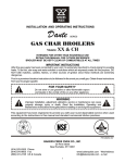
INSTALLATION AND OPERATING INSTRUCTIONS Gas Char Broilers Model: SGBR and GG INTENDED FOR OTHER THAN HOUSEHOLD USE RETAIN THIS MANUAL FOR FUTURE REFERENCE FOR YOUR SAFETY Do not store or use gasoline or other flammable vapors or liquids in the vicinity of this or any other appliance. WARNING Improper installation, adjustment, alteration, service or Maintenance can cause property damage, injury or death. Read the Installation, Operating and Maintenance Instructions thoroughly before installing or servicing this equipment. This equipment has been engineered to provide you with year round dependable service when used according to the instructions in this manual and standard commercial kitchen practices. Instructions must be posted in a prominent location. All safety precautions must be taken in the event the user smells gas. Safety information can be obtained from your local gas supplier. G DESI N ® CE R TIFIED R CERTIFIED R BAKERS PRIDE OVEN CO., INC. (914) 576-0200 Phone (914) 576-0605 Fax 30 Pine Street New Rochelle, NY 10801 1 P/N U4010A 5/97 (800) 431-2745 US & Canada www.bakerspride.com WebAddress TABLE OF CONTENTS 1. INSTALLATION INSTRUCTIONS SECTION 1 2 3 4 5 6 7 Additional Installation Requirements 8 Installation with Casters PAGE 3 3 3 4 5 5 5 5 5 6 6 6 7 7 2. OPERATING INSTRUCTIONS 5 Warranty 12 2 1. INSTALLATION INSTRUCTIONS 1. INSTALLATION: (a) In USA, installation of this broiler must conform with the latest edition of the American National Standard Z-223.1 National Fuel Gas Code and/or local codes. In Canada, installation must conform with the latest edition of CAN/CGA-B149.1 or 2 Installation Code and/or local codes. (b) This broiler when installed, must be electrically grounded in accordance with local codes, and/or the latest edition of the National Electrical Code ANSI/NFPA No. 70 in USA (Canadian Electrical Code CSA C22.2 in Canada). 2. ACCEPTABLE CLEARANCES: Due to intense heat generated by radiation, these broilers should be installed in noncombustible locations only, including above the grate level. MINIMUM CLEARANCE FROM NON-COMBUSTIBLE"CONSTRUCTION: RIGHT SIDE LEFT SIDE 0 0 BACK 0 3. GAS CONNECTION: The gas pressure regulator supplied must be installed at the gas inlet of each broiler. Each regulator is adjusted to yield a manifold pressure of 5" water column (12.5 mbar) for Natural Gas or 10" water column (25 mbar) for Propane Gas. No pressure regulator is required for propane gas in Canada. Recommended minimum gas supply lines are listed below: All GG Models 1" (25 mm) SGBR-1 thru SGBR-3 1" (25 mm) SGBR-4 thru SGBR-9 1 1/2" (38 mm) 3 For units using Propane Gas, supply lines with less than 1/2D (12.7 mm) inside diameter should not be used, even for a small unit. On the GG Series, the gas may be connected either in the rear or the bottom of the unit. NOTE: Be sure plug is installed in the connection not being used. On the SGBR Series the gas manifold extends out on each side near the front of the unit. Gas can be connected from either side. Be sure to cap whichever side is not connected. NOTE: A shut-off valve in a readily accessible location must be mounted on the gas supply line before the unit. When making gas pipe connections, pipe joint compound resistant to the action ofJiquefied petroleum gases should be used. The broiler and its individual shutoff valve must be disconnected from the gas supply piping system during any pressure testing of that system at test pressures in excess of 1/2 psig (3.45 kpa). The broiler must be isolated from the gas supply piping system by closing its individual manual shutoff valve during any pressure testing of the gas supply piping system at test pressures equal to or less than 1/2 psig (3.45 kpa). 4. BURNERS: Check to see that AIR MIXER CAPS on the front of all burners are adjusted and tightened allowing half the opening in the burner to show. Install burners following the steps below: Please note that the straight burner (without the arm) is installed on the extreme right side on models GG-2, GG-4 and GG-6 (see figure 5 ). On the model GG-8 which has two straight burners (without arms), install one burner to the extreme right of the unit and the second straight burner to the left of the center divider. On the SGBR Series, only straight burners are used. 4 Step 1. Place the front of the burner (flat side up) into the valve assembly by fitting the center hole of the air mixer cap over the brass orifice. Step 2. Swing the rear end of the burner and seat it into place over the burner support pin on the back of the unit. NOTE: Due to the compactness of the design, it is usually necessary to swing one burner away to get the next one out. 5. ASSEMBLY PROCEDURES: a. Bottom Grates: GG Series: Place the Cast Iron Bottom Grates on the front and rear ledge of the bucket assembly above the burners with the flat side facing up and the tapered edge facing down toward the burners. SGBR Series: Place the Stainless Steel Mesh Bottom Grates on the angle iron supports above the burners. b. Glo-Stones: Spread one layer of Glo-Stones covering all bottom grates. Do not use more than one ,layer as this will reduce the amount of heat reaching the top grates and could reduce the life of the bottom grates. c. Top Grates: Place the Top Grates over the glo-stones with the wavy ribs face up. These grates are designed to give a minimum of meat to metal contact. The top grates should be positioned so that the grease drains built into each rib carry excess fat to the grease chute. The grease chute is located in the rear on the GG series and in the front on theSGBR Series. d. Griddle Plates If Griddle Plates are used, they should not cover more than 50% of the broiling area. Each Griddle Plate covers the same area as two top grates. For GG Series broilers, the Griddle Plates should be placed on top of the top grates. For SGBR Series broilers, the Griddle Plates should replace the top grates. 5 6. LIGHTING PROCEDURE: a. GG Series There are two pilot burners and shut off valves, (except for model GG-2 which only has one) one for the right half and another for the left half of the unit. To light the pilot burners: 1. Turn all broiler valves to the "OFF" position. 2. Open main gas shut off valve (supplied by customer) 3. Allow air to bleed from the gas line through the pilot burners. 4. Light the pilot burners using a lit taper through the open areas above the salamander rack below the burners. The pilot burner can also be lit by using a lit taper from above the burners before the top grates, bottom grates and glo-stones are installed. 5. With a screwdriver adjust the pilot valves to provide a 1/2" (12.7 mm) flame. 6. Turn right burner control valve "ON" to light burners on the right half of the unit, 7. If any burner fails to light, turn the burner valves to "OFF", wait five minutes and repeat the above procedure. 8. To shut down the unit, turn both burner control valves "OFF". Turn clockwise to reduce or counter clockwise to increase the pilot burner. and turn left burner control valve "ON" to light burners on the left side of the unit. CAUTION: THE PILOT BURNERS WILL STAY LIT UNTIL THE MAIN GAS SUPPLY TO THE UNIT IS TURNED "OFF". WAIT AT LEAST 5 MINUTES BEFORE ATTEMPTING TO RELIGHT. b. SGBR Series Each burner has a standing pilot burner which must be lit before the burners can be lit. To light the pilot burners: 1. Turn all broiler valves to the off position. 2. Open main gas shut off valve (supplied by customer). 3. Allow air to bleed from the gas line through the pilot burners. 4. Light the pilot burners using a lit taper through the open areas above the salamander rack below the burners. The pilot burners can also be lit by using a lit taper from above the burners before the top grates, bottom grates and glo-stones are installed. 5. With a screwdriver, adjust the pilot valves to provide a 1/2" (12.7 mm) flame. Turn clockwise to reduce or counter clockwise to increase the pilot burner. 6. Turn each burner control valve "ON" to light burners. 7. If any burner fails to light, turn the valve to "OFF", wait five minutes and repeat the above procedure. 6 8. Each burner may now be adjusted to the desired flame size by turning the individual burner valve handle. 9. To shut down the unit, turn all valves "OFF". NOTE: THE PILOT BURNERS WILL STAY LIT UNTIL THE MAIN GAS SUPPLY TO THE UNIT IS TURNED "OFF". CAUTION: AFTER TURNING BROILER CONTROL VALVES OFF, ALWAYS WAIT AT LEAST 5 MINUTES BEFORE ATTEMPTING TO RELIGHT IF PILOT BURNER GOES OUT. 7. ADDITIONAL INSTALLATION REQUIREMENTS: a. Keep the area around the broiler free and clear of combustible materials. b. The provisions of an adequate air supply to your broiler is essential. Provide for sufficient air to enter the broiling area and assure that this air flow is not obstructed. c. Air enters the burner area from the front and bottom of your broiler. Assure that these areas are kept open and unobstructed. d. . Servicing is accomplished through the front and top of the broiler. Assure. that these areas are kept unobstructed for proper servicing and operation. 8. INSTALLATION WITH CASTERS: a. b. Install the casters with wheel brakes on the front of the appliance. Installation should be made with a connector that complies with the latest edition of the Standard connectors for Movable Gas Appliances ANSI Z21.69 in USA (CAN CGA6.16 in Canada) and a quick disconnect Device that complies with the latest edition of the Standard for Quick Disconnect Devices for use with gas fuel ANSI Z21.41 in USA (CAN 16.7 in Canada) and adequate means must be provided to limit the movement of the appliance without depending on the connector and any quick disconnect device or its associated piping to limit the appliance movement. c. The restraint should be attached to one of the legs on which the casters are mounted. d. If disconnection of the restraint is necessary, the restraint should be reconnected after the appliance has been returned to its originally installed position. 7 II. OPERATING INSTRUCTIONS 1. LIGHTING PROCEDURE: See Section 6 of Installation Instructions. Once the pilot burners are lit, the broiler may be turned ON or OFF by turning the control valves ON or OFF as necessary. 2. BROILING PROCEDURE: BROILER TOP GRATES MUST BE HOT ENOUGH TO MAKE BLACK CHAR-MARKS WHEN STARTING TO BROIL. Adequate pre-heating time is necessary for the food to release from the broiler and to cook properly. Allow the unit to pre-heat for 45 minutes to 1 hour before broiling. (a) Do not press the juice out of the meat because that will cause dry products. (b) After broiling, allow the meat to sit covered on a heated platter for 2-5 minutes before cutting. This will allow the juices to "Settle" and the product will be more moist. (c) Do not use forks or other sharp objects to poke holes in the meat. Do not cut the meat as it cooks. (d) Thick pieces of meat require a longer broiling time with less flare-up. Reduce flare up by trimming excess fat for a longer broiling time without burning. (e) Keep the unit clean. Food caught between the grate will not allow hot air to rise around the product. This will result in uneven heating and increase the cooking time. 3. MAINTENANCE: (a) SERVICE: Shut off the main gas supply before attempting any maintenance on the unit. If required, contact your Dealer, the Factory, or a local Service Company to obtain qualified maintenance and repairs. 8 (b) CARE AND CLEANING OF TOP GRATES: The top grates should be cleaned using a stiff wire brush. If this is done daily, the accumulation of food and fat caught in the grates and work necessary to keep them clean will be reduced. Periodically they should be turned over and brushed and then put back. In the event that an extra amount of fat is accumulated on the top, due to use of low heat, we recommend turning up the flame of this section for about an hour, which will burn off much of the fat and residue and the Under no circumstances should the grates be placed in a dishwasher. Soap, water, or any detergent should never be used on the cast iron grates. NOTE: The following procedures should only be done when the unit is cold. DO NOT attempt steps c, d, or e when the unit is hot. brushing operation will be easier. (c) CARE OF GLO-STONES: On a weekly basis, the top grates should be removed and the Glo-Stones mixed about to break away any carbon deposit so that it falls through the bottom grates. Spread the Glo-Stones evenly and add only the amount necessary for a single layer. (d) CARE OF BOTTOM GRATES: Periodically,'push all the Glo-Stones to one side and inspect the bottom grates. If necessary brush the grates with a wire brush. If the grates are cracked, broken or deteriorated they should be replaced. (e) CARE OF THE BURNERS: All the burners should be checked at the same time as the bottom grates. Grease build up on the burners should be removed with a wire brush. Make sure all the burner ports are clean. A thin sharp object can be used to clean the burner ports if necessary. (f) GREASE COLLECTION: GG series char-broilers are designed to bring grease to the rear of unit from where the grease drips into the grease collection pan in the lower section of the broiler. SGBR Series char-broilers are designed to bring grease into the front channel which in turn drains the grease into the grease collection pan in the lower section of the broiler. The grease collection pans in the lower section should be cleaned daily or more often if necessary. The channel should be cleaned periodically with a stiff brush or scraper. (g) CLEANING TOOLS: Several models of specially designed top grate brushes and grease drain scrapers are available from Bakers Pride. Contact Bakers Pride for more information. 9 4. ILLUSTRATIONS FIG. 1 SGBR SERIES AIR MIXER CAP AND PILOT BURNERS ORIFICE HOLDER PILOT BURNERS BURNER BURNER VALVE EXTENSION (STRAIGHT) AIR MIXER CAP VALVE HANDLE PILOT FLAME ADJUSTING SCREW MANIFOLD ORIFICE BURNER VALVE MANIFOLD VALVE EXTENSION (CURVED) FIG. 3 GG SERIES FIG. 4 GG SERIES - TYP. SIDE VIEW PILOT BURNER BURNER ORIFICE VALVE HANDLE MANIFOLD VALVE 10 FIG. 5 GG SERIES FIG. 6 SGBR SERIES 11 5. BAKERS PRIDE LIMITED WARRANTY 30 Pine Street New Rochelle, New York 10801 914 / 576 - 0200 US & Canada: 1 - 800 - 431 - 2745 fax 914 / 576 - 0605 WHAT IS COVERED This warranty covers defects in material and workmanship under normal use, and applies only to the original purchaser providing that: The equipment has not been accidentally or intentionally damaged, altered or misused; ! The equipment is properly installed, adjusted, operated and maintained in accordance with National and local ! codes, and in accordance with the installation instruction provided with the product; The serial number rating plate affixed to the equipment has not been defaced or removed. ! WHO IS COVERED This warranty is extended to the original purchaser and applies only to equipment purchased for use in the U.S.A. COVERAGE PERIOD Cyclone Convection Ovens: BCO Models: One (1) Year limited parts and labor; GDCO Models: Two (2) Year limited parts and labor; CO11 Models: Two (2) Year limited parts and labor; (5) Year limited door warranty. All Other Products: One (1) Year limited parts and labor. Warranty period begins the date of dealer invoice to customer or ninety (90) days after shipment date from BAKERS PRIDE whichever comes first. WARRANTY COVERAGE This warranty covers on-site labor, parts and reasonable travel time and travel expenses of the authorized service representative up to (100) miles, round trip, and (2) hours travel time. The purchaser, however, shall be responsible for all expenses related to travel, including time, mileage and shipping expenses on smaller counter models that may be carried into a Factory Authorized Service Center, including the following models: PX-14, PX-16, P18, P22S, P24S, PD-4, PDC, WS Series and BK-18. EXCEPTIONS All removable parts in BAKERS PRIDE Char-broilers, including but not limited to: Burners, Grates, Radiants, Stones and Valves, are covered for a period of SIX MONTHS. All Ceramic Baking Decks are covered for a period of THREE MONTHS. The installation of these replacement decks is the responsibility of the purchaser. The extended Cyclone door warranty years 3 through 5 is a parts only warranty and does not include labor, travel, milage or any other charges. EXCLUSIONS Failures caused by erratic voltages or gas supplies, Unauthorized repair by anyone other than a BAKERS PRIDE Factory Authorized Service Center, Damage in shipment, Alteration, misuse or improper installation, Thermostats and safety valves with broken capillary tubes, Accessories spatulas, forks, steak turners, grate lifters, oven brushes, scrapers, peels, etc., Freight other than normal UPS charges, Ordinary wear and tear. Negligence or acts of God, Thermostat calibrations after (30) days from equipment installation date, Air and Gas adjustments, Light bulbs, Glass doors and door adjustments, Fuses, Char-broiler work decks and cutting boards, Tightening of conveyor chains, Adjustments to burner flames and cleaning of pilot burners, Tightening of screws or fasteners, INSTALLATION Leveling and installation of decks, as well as proper installation and check out of all new equipment per appropriate installation and use materials is the responsibility of the dealer or installer, not the manufacturer. REPLACEMENT PARTS BAKERS PRIDE genuine Factory OEM parts receive a (90) day materials warranty effective from the date of installation by a BAKERS PRIDE Factory Authorized Service Center. This Warranty is in lieu of all other warranties, expressed or implied, and all other obligations or liabilities on the manufacturers part. BAKERS PRIDE shall in no event be liable for any special, indirect or consequential damages, or in any event for damages in excess of the purchase price of the unit. The repair or replacement of proven defective parts shall constitute a fulfillment of all obligations under the terms of this warranty. Form #U4177A 1/03 4/02 12