1
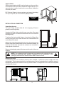
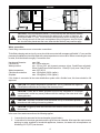
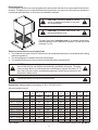
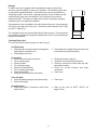
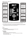
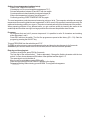
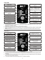
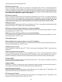
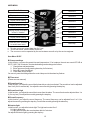
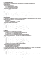
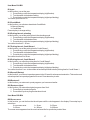
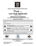
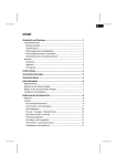
SERVICE & INSTALLATION MANUAL
COMBI KING
Models: C & K
Phone:
Fax:
Toll Free:
Website:
E-mail:
Edition 1.2X 8/08
(864) 963-3471
(864) 963-5316
(800) 927-6887
www.bkideas.com
[email protected]
BKI Worldwide Headquarters
PO Box 80400
Simpsonville, SC 29680-0400 USA
1
TABLE OF CONTENTS
ITEM
PAGE
Approval plate
3
INSTALLATION AND CONNECTION
Unpacking the Oven
Installing the Oven
Water connection
Drain connection
Electrical connection/survey of supply lines
Supply Lines - Survey
Exhaust
Checking Before Use
On the Outside
Connections
Oven Chamber
3
3
3
4
5
5
5
6
6
6
6
6
OPERATION PANEL
Settings
Setting of Temperature
Setting of Time
Setting of Core Temperature
Programs
Entering and Changing Text
7
7
7
7
8
8
8
START MENU
9
OVEN SET-UP
Set-up Mode U
Set-up mode U1 to U15
Test Mode
Test Mode D0 To D6
Test Mode D7 To D15
Test Mode D16 To D20
Test Functions D21 To D28
Test Mode D29 To D47
9
10
10
11
11
12
13
13
14
USER MENU
User Menu B1 TO B7
User Menu B8 TO B13
User Menu B14 TO B21
User Menu B22 TO B24
15
15
16
17
17
ERROR CODES
18
ANNUAL SERVICE CHECK
20
APPENDIX 1
BKI Installation Checklist
21
21
APPENDIX 2
BKI Instruction Checklist
22
22
Warranty
24
2
Approval Plate
When communicating with BKI, we kindly ask you inform us of the
serial number of the oven that is stated on the approval plate. The
approval plate is usually located on the oven cabinet, behind the
oven door, as shown.
BKI Technical Support, whose experience and expert knowledge
are at your disposal, can be contacted at (800) 927-6887.
APPROVAL
PLATE
INSTALLATION & CONNECTION
Unpacking the oven
The oven is best handled while still in its wrapping. Wherever
possible, use a lifting trolley.
Introduce the lifting trolley under the lower cross tube of the stand
and place a couple of wooden blocks between the cross tube and
the lifting trolley.
To achieve the best possible balance, introduce the lifting trolley
from the front of the oven or from the motor side. Note that the oven
can be lifted off the stand.
Remove the original packaging from the oven. Do not remove the
foil that covers the surfaces until the oven has been installed, as
once the foil has been removed the surfaces are vulnerable to
sharp objects such as tools.
Remove all packaging material that secures the racks in the oven
chamber.
!
NOTE: The packaging should be destroyed in accordance with national rules and
regulations governing waste disposal. Information on the composition of the
packaging material can be obtained from the BKI Customer Center.
!
Installing the oven
To ensure that the oven functions correctly when installed, it should be placed upright and level
(horizontally). This is measured at the front and side edge of the roof, and adjustment is made by means of
the adjusting screws on the stand or on the legs of table models. The height of the oven can also be adjusted
to fit the trolley for rack.
CORRECT
3
WRONG
!
CAUTION: The oven should be placed 2” (5 cm) from the rear wall and the distance
between the right side of the oven and the nearest wall or piece of furniture, etc.
should be at least 3” (7 cm). This is to ensure the necessary flow of cooling air to the
oven. Strong sources of heat such as hotplates, tilting frying pans, deep fat fryers,
etc. should not be placed near the oven, otherwise the warranty may cease to apply.
!
Water connection
Combi King ovens have one or two water connections.
To facilitate cleaning and service, the oven should be connected with an approved flexible ½” hose and the
permanent installations should be fitted with a stop-tap and a non-return valve. Before connecting the oven
to water, flush the tubes thoroughly. Connect the oven.
Hardness of the water:
Conductivity:
Water pressure:
Water temperature:
Chloride concentration:
Sulphate:
max. 3 dH
min. 75 microsiemens
min. 2.5 bar (36.3 psi) dynamic pressure (when CombiClean activated).
When CombiClean not activated: min. 1.5 bar (21.8 psi), max. 6 bar (87 psi).
max. 68°F (20°C)
max. 100 mg/litre (.083 lb./gallon)
max. 150 mg/litre (.125 lb./gallon)
If the feeder is connected to the water distribution system with a flexible hose, this hose should be VA
approved.
!
CAUTION: If the water temperature exceeds 68°F (20°C), problems with regard to
ClimaOptima calibration and cooling of the oven may occur.
!
!
CAUTION: Ovens with a steam generator must not be connected to a reversed
osmosis plant, as this may cause problems with the reading of the water level in the
steam generator.
!
!
CAUTION: The water connection must be carried out by an authorised plumber in
accordance with existing rules and regulations.
!
!
CAUTION: Clogged up water filters and dirt in the solenoid valves are not covered by
the warranty.
!
In the case of two water connections, the following applies:
1. 1 connection for raw water for the condensation jet (cold water).
2. 1 connection for the steam generator and the jet in the oven chamber. Must meet the requirements
applying to water supplied to household appliances; however, hot water with a temperature not
exceeding 122°F (50°C) can be used.
4
Drain connection
From the factory, the BKI ovens are equipped with a drain system that removes surplus water from the oven
chamber. This water may be condensed water from the products, or it may occur when the oven chamber is
cooled down with cold water, or when the oven chamber is cleaned.
!
CAUTION: Connection must be carried
out by an authorised plumber, to an open
or to a closed drain.
!
!
CAUTION: The drain must never end
directly beneath the oven.
!
The drain must be of stainless steel or an equally temperatureresistant material, have a diameter of at least 2” (50 mm) and a fall
of at least 3° or 5%.
Electrical connection/survey of supply lines
The electrical connection must be carried out by an authorised electrician in accordance with existing
rules and regulations.
! The wiring diagram is located in the motor compartment.
! The terminal for the electrical connection is located behind the right side plate.
!
!
CAUTION: An approved plug outlet or a safety cutout must be located close to the
oven so that the oven can be disconnected during installation and repair. The safety
cutout must be able to cut off all poles with a total distance of break of at least .12” (3
mm). Each of the two units in a stacked arrangement (CombiPlus) must have its own
plug outlet or safety cutout
!
!
The warranty does not cover incorrect connection.
!
Supply lines - survey (applies to all models (C, B, K, CPE, BPE, KPE)
(All cross sections in mm² )
1.06
400V 3N ~ 50/60 Hz
400V 3 ~ 50/60 Hz
415V 3N ~ 50/60 Hz
440V 3 ~ 50/60 Hz
200V 3 ~ 50/60 Hz
230V 3 ~ 50/60 Hz
230V 1 ~ 50/60 Hz
480V 3 ~ 50/60 Hz
208V 3 ~ 50/60 Hz
9 kW
5x2,5
4x2,5
5x2,5
4x2, 5
4x4
4x4
3x10
4x2,5
4x4
1.08 - 1.10 - 1.08 - 1.10 1.12
1.12
Fuse
18 kW
Fuse
16A
5x4
35A
16A
4x4
35A
16A
5x4
25A
4x4
16A
25A
35A
63A
4x16
25A
50A
4x10
3x25
50A
80A
16A
25A
4x4
25A
4x10
50A
1.06
*Not Possible
Fuse
2.10
2.14
27 kW
2.10
2.14
Fuse
5x16
4x16
5x10
4x10
4x35
4x35
63A
63A
50A
50A
125A
100A
5x10
4x10
5x10
4x6
4x25
4x25
50A
50A
50A
35A
80A
80A
*
4x10
4x35
*
50A
100A
*
4x6
4x25
*
35A
80A
1.16
1.16
1.20
1.20
24 kW
5x10
4x10
5x10
4x10
4x25
4x25
Fuse
50A
50A
50A
50A
100A
80A
36 kW
*
4x6
4x25
*
35A
80A
Recommended Supply Line: H07RN-F
5
Exhaust
The BKI ovens are equipped with an open/direct exhaust system that
removes surplus humidity from the oven chamber. The exhaust system has
an electrically operated damper. The exhaust tube can be connected to a
ventilating system. In that case, a special extraction funnel is fitted to avoid
suction directly from the oven chamber. This extraction funnel can be
ordered from BKI. The scope of supply also includes a specially designed
extraction hood, see adjacent illustration.
If an extraction hood is installed in the ceiling above the oven, it should project
20” (50 cm) over the front of the oven. The suction effect should be 400 – 800
m3/h (523 - 1046 yd3/h).
The ventilation motor can be controlled directly from the oven. This means that
the ventilation starts when a program is started and runs for 10 minutes after the
program is completed.
Checking Before Use
The oven should be checked before you start using it.
On The Outside
Check that the oven has not been damaged in
transit (dents, scratches, etc.)
! Check/adjust oven door
!
!
Check/adjust the height and check that the
oven is placed level (horizontally)
!
!
!
!
Check connection to trip tray
Check for correct mounting of drip tray
Check for correct fall of hose from drip tray,
and check for leaks
Check for correct exhaust and drain
connection
Clean oven
Oven chamber
Check that filter housing is mounted correctly
Check interior light
!
Clean oven
Operation panel
! Check and adjust, if necessary, each of the
preset values
!
Heat up the oven at 482°F (250°C) for
approx. 5 min.
Connections
! Check for correct water connection
! Turn on water supply
! Check for leaks
! Turn off water supply
! Check and clean dirt filter
! Turn on water supply again
! Check handshower
! Check for correct electrical connection
!
!
!
6
OPERATION PANEL - MODELS C & K
Main switch
TEMPERATURE SETTING.
Press once and set
temperature with TURN
SWITCH. Enter by
pressing symbol again.
HOT AIR 30-250°C. All
modes and all optional
extras are described on
following pages.
Preheating up to 300°C
is a standard feature on
models C and K.
TIME SETTING. Press once
andset time with TURN
SWITCH. 4 hours is
maximum. Confirm by
pressing TIME.
SETTING CORE TEMP.
PROBE (optional extra).
Press once and set with
TURN SWITCH. Deactivate
by turning switch past the
permitted temp. Range of
30-99°C.
PROGRAMS. Press once
and choose program with
TURN SWITCH. Editing and
deleting are described on
following pages.
888
88:88
888
PRG
REGENERATING /
COMBI STEAMING
Change between the
modes by pressing
REGENERATING
COMBI STEAMING 1
COMBI STEAMING 2
8888888888
8
½
STEAMING 30-120°C (2).
Used for manual humidity
pulsing in HOT AIR during
preparation.
EXHAUST is open when
control lamp is on. Low
FAN SPEED is active
when control lamp is on.
STEP shows current step
when PROGRAM mode is
active. Control lamp next to
ALARM lights up when
alarm after a step has been
chosen (when PRG is
active).
Turn switch
ON/OFF
(1) If the oven does not incorporate CombiWash, the manually operated cleaning system can be activated
by pressing the PRG key and turning the turn switch until CLEANING appears in the display.
(2) The C model has no steam generator, but this mode makes it possible to steam in the oven anyway. At
temperatures between 65 and 100°C, you can steam all kinds of vegetables, rice, pasta, meat and fish.
In the following, this mode will be referred to as “Combi steaming 3”.
Settings
Setting of temperature:
Press TEMPERATURE key once and set temperature with turn switch.
Confirm by pressing TEMPERATURE key again.
Setting of time:
Press TIME key.
Time flashes.
Choose desired time (hours and minutes) with turn switch.
If switch is turned all the way down to 0,”-:--” (continuous operation) appears in the display.
Max. time setting is 4 hours.
Confirm by pressing TIME key again.
7
Setting of core temperature (optional extra):
Press CORE TEMPERATURE key.
If the display is off, the core temperature appears as 75°C.
Set core temperature between 30 and 99°C with turn switch.
Core temperature is deactivated by turning switch past 30.
When core temperature is chosen, time changes to ”-:--” .
Confirm by pressing CORE TEMPERATURE key again.
The core temperature probe has several measuring points on its tip. The computer calculates an average
temperature thus ensuring that the core temperature is 100% correct. If the probe is inserted incorrectly, the
advanced technology notifies you at once. The probe is inserted vertically in the thickest part of the product.
When preparing products of very different sizes, you get a uniform quality by inserting the sensor in the
smallest product and then moving it to a larger product when the core temperature alarm sounds.
Programs:
10 programs that can hold 3 process steps each. It is possible to write 10 characters and entering
alarm after steps 1 and 2.
Press PRG and turn the switch. The first five programs are preset at the factory (P0 – P4). Start the
program by pressing the ON/OFF key.
To leave PROGRAM, turn the switch beyond ”P O”.
To delete an entire program, press core temperature key and alarm key simultaneously for 2 seconds.
When the keys or the turn switch is idle for 20 seconds, the oven returns to manual operation.
Entering and changing text:
To enter or change text, press PRG for 3 seconds.
The first digit or the relevant letter/”_” flashes alternately. Change the flashing character with the turn
switch. You can choose between all the letters of the alphabet and the digits 0 – 9.
The space sign is next to the letter A.
Move on to the next digit by pressing PRG briefly.
Store text by pressing PRG until “SAVED” appears in the display.
To leave text editing without storing, press ALARM. The original text reappears.
8
START MENU
HOT AIR selected if control
lamp on
Main switch
Change oven temperature
with turn switch
COMBI STEAMING selected
if upper or middle control
lamp is on. REHEATING is
selected if lower control lamp
is on.
Change time with turn switch
Core temperature on C & K
Models. Injection time on
B model.
Steaming on C & K.
Preheating on B.
Exhaust open if
control lamp on.
Program key
Step key
!
!
!
!
Alarm key
Fan speed can be set between
20 and100%. Control lamp is
on when speed < 100.
Start/Stop
Turn switch
Set temperature (press temperature key, temperature flashes, set temperature with turn switch, press
temperature key again to save).
Set time (press time key, time flashes, set time with turn switch).
Set core temperature (press core temperature key, set temperature with turn switch). C and K models
only.
Set injection time (press injection key, time flashes, set injection time with turn switch). B model only.
OVEN SET-UP
Main switch
Press HOT AIR and
STEAMING for 2 seconds
Display shows setting
Possible to change to “d” test
mode with combi steam key
Not active
Display shows “U” No.
Press STEAMING/
PREHEATING and HOT AIR
for 2 seconds
Display shows description of
“U” function
Not active
Display shows setting
Not active
Confirmation of special
settings
Select “U” settings with
turn switch
Not active
!
!
!
!
To enter set-up mode, press hot-air key and steaming/preheating key for 2 sec.
To leave set-up mode, turn switch to the left. Change between set-up and test mode by pressing combisteam key.
The set-up mode is only intended for service engineers who wish to change the set-up of the computer
control of the oven model in question.
The program display shows a description of the "U" function in question.
9
Set-up Mode U
In the set-up function, it is possible to set the oven controller to match the mechanical set-up and the choice
of software.
If the set-up has been changed in U1, U4 or U15, the oven will be reset.
U1 Oven model
You select the oven model (B, C or K) by pressing the step key. 1= K, 2= C, 3= B.
You press the temperature key to select a Pass-Through model (two doors).
1= one door (standard) 2= two doors
When you have selected the oven model, confirm by pressing the alarm key if the control lamp flashes.
After that, the controller initialises. NOTE: ALL settings and programs are reset.
U2 Oven size
You choose the oven size by pressing the step key: 0-7.0= 1.06, 1= 1.08, 2= 1.10, 3= 1.12, 4= 1.16, 5= 1.20,
6= 2.10, 7= 2.14. The oven size you have chosen is shown in the field next to the temperature key.
U3 CombiClean
You activate or deactivate CombiClean by pressing the step key. 0=OFF, 1=ON.
U4 Temperature scale
You choose between Celsius and Fahrenheit as scale of temperature by pressing the step key.
0= Celsius 1= Fahrenheit.
You can ”even out” the current temperature by pressing the temperature key.
0=OFF, 1=ON When you have chosen the temperature scale, confirm by pressing the alarm key if the
control lamp flashes. After that, the controller initialises. NOTE: ALL settings and programs are reset.
U5 Not in use
U6 Low-temperature steaming
You activate and deactivate low-temperature steaming by pressing the step key.
0= OFF, steaming only possible at 212°F (100°C), 1= ON, steaming only possible between 86°F (30°C) and
248°F (120°C).
NOTE: This function is available on K models only. If chosen on a B or C model, nothing happens.
U7 Preheating at 572°F (300°C)
You activate and deactivate preheating by pressing the step key. 0= OFF, 1= ON.
NOTE: Preheating at temperatures above 484 °F (250°C) is only possible for max. 15 minutes.
U8 Setting water level sensor
When you press the temperature key, the water level value starts flashing and can then be set between 40
and 80 (default 70). If the conductivity of the water is low, set the water level higher.
U9 Automatic restart
You activate and deactivate automatic restart by pressing the step key.
0= OFF, 1= 10 minutes, 2= 30 minutes, 3= 60 minutes. This means that if there is a power cut, the program
that was interrupted will be resumed provided that the power returns within the time set.
U10 Programs
You activate the program mode by pressing the step key. 0= OFF, 1= 10 programs with 3 process steps.
NOTE: It is still possible to activate the cleaning program even though the program mode is active.
0= OFF.
U11 Core temperature probe
You activate and deactivate the core temperature probe by pressing the step key. 0= OFF, 1= ON.
U12 Drain cooling
You activate and deactivate drain cooling by pressing the step key. 0= OFF, 1= ON.
U13 Timer start
You activate or deactivate timer start by pressing the step key. 0= OFF, 1= ON.
10
U14 Demo
You activate or deactivate the demo mode by pressing the step key. 0= OFF, 1= ON.
NOTE: If the demo mode is on (1= ON), the oven will run without heating elements and steam
generator being switched on. When the oven starts, it will let you know whether the demo mode is
on.
U15 Initializing
You reset the controller by pressing the alarm key.
Test Mode
For test mode, press HOT
AIR and COMBI
STEAMING for 2 seconds
Main Switch
Display shows setting
For test mode, press
COMBI STEAMING and
HOT AIR for 2 seconds
Display shows setting
Display shows “d” No.
Possible to change to”U”
setting by pressing
STEAMING/PRE-HEATING
Display shows description
of the “d” function
Display indicates whether
the function is active
Not active
Activates each function
briefly
Not active
Possible to choose a “d”
function with turn switch
Not active
!
!
!
!
To enter test mode, press hot-air key and combi-steam key for 2 sec.
To exit test mode, turn switch left. Change between set-up mode and test mode by pressing
steaming/preheating key.
How to operate the selected component: You turn the component on (1) and off (2) by pressing the step
key. Or, you press the alarm key, and the component is active for as long as you press the key.
The set-up mode is only intended for service engineers who wish to test the various modes/functions.
TEST MODE D0-D6
In the test mode, it is possible to activate all electrical components. This is very useful in connection with
fault detection and the testing and adjusting of replacement parts.
D0 Main contactor(s)
This function activates contactor K1. You activate or deactivate the function by pressing the step key. The
function can, however, only be activated when the fan is on. To pulse, press the alarm key. 0= OFF, 1= ON.
Status for the main alarms appear in the display as follows:
Digit 4 Solid State Relay
Digit 1 fan
Digit 2 oven Digit 3 generator
If ER28 appears, the alarm sensor circuit board or wiring harness is defective.
D1 Oven heat
This function activates contactor K2. You activate or deactivate the function by pressing the step key.
Humidity pulsing is possible by pressing the alarm key. 0= OFF, 1= ON.
11
D2 Steam generator heat
Available on K models only This function activates contactor K3. You activate or deactivate the function by
pressing the step key. However, this function can only be activated when there is water in the steam
generator. To pulse, press the alarm key. 0= OFF, 1= ON.
D3 Fan, right-hand, high/low
This function activates the frequency exchanger. You can test the speed of the motor by pressing the step
key. 0= OFF, 2= ON
By pressing the time key, it is possible to adjust the speed of the motor from 0 to 100%. The RPM appears in
the temperature display.
Note: The main contactor K1 must be active for this function to work, as the frequency transformer
is connected via K1
D4 Fan, left-hand, high/low
This function activates the frequency exchanger. You can test the speed of the motor by pressing the step
key. 0= OFF, 2= ON
By pressing the time key, it is possible to adjust the speed of the motor from 0 to 100%. The RPM appears in
the temperature display.
Note: The main contactor K1 must be active for this function to work, as the frequency transformer
is connected via K1
D6 Solenoid valve
This function activates solenoid valve MV1. You activate or deactivate the function by pressing the step key
To pulse, press the alarm key. 0= OFF, 1= ON.
TEST MODE D7-D15
D7 Filling valve (Available on K models only).
This function activates solenoid valve Mv2. You activate or deactivate the function by pressing the step key.
To pulse, press the alarm key. 0= OFF, 1= ON.
D8 Drain pump (Available on K models only).
This function activates motor M2. You activate or deactivate the function by pressing the step key. To pulse,
press the alarm key. 0= OFF, 1= ON.
D9 Drain cooling (This function is not available on B models).
This function activates solenoid valve Mv3. You activate or deactivate the function by pressing the step key.
To pulse, press the alarm key. 0= OFF, 1= ON.
D10 Damper motor
This function activates motor M3. In the display next to ”Time”, it is possible to read the status of the damper
motor switch. OFF= damper open, ON= damper closed. You activate or deactivate the function by pressing
the step key. To pulse, press the alarm key. 0= OFF, 1= ON.
D11 Exhaust
This function activates the outlet for controlling the external ventilation, terminals 4 and 5. In the display next
to ”Time”, it is possible to read which outlet is active. OFOF= both outlets are off, ONOF= outlet 4 is active
and outlet 5 is off. OFON= outlet 4 is off and outlet 5 is active. ONON= both outlets are active. You activate or
deactivate the function by pressing the step key. 0= OFOF, 1= OFON, 2= ONOF, 3= ONON.
D12 Cooling fan
This function activates motors M7 and M7A. You activate or deactivate the function by pressing the step
key. To pulse, press the alarm key. 0= OFF, 1= ON.
D14 Interior light
This function activates H1. You activate or deactivate the function by pressing the step key. To pulse, press
the alarm key. 0= OFF, 1= ON.
12
D15 Oven temperature
Here it is possible to read the current oven temperature, P1. In the field next to ”Temperature”, the current
temperature is shown. If ERR appears, the sensor circuit is defective. In the field next to ”Time”, an
adjustment value between 80 and 120 (default 100) is shown. To adjust the temperature, press the time key
until the digit in the display flashes. Then adjust upwards or downwards until the correct temperature is
shown. Finally, press the time key again to save the setting. The temperature can be adjusted by +- 50°F (+10°C).
TEST MODE D16-D20
D16 Core temperature (This function is not available on B models).
C and K models can use only one core temperature probe, it is possible, however, to test core
temperature probes 1 and 2.
Here it is possible to read the current temperature of the core temperature sensor, P2 + P2A. In the field next
to ”Temperature”, the current temperature is shown. If ERR appears, the sensor circuit is defective. In the
field next to ”Time”, an adjustment value between 80 and 120 (default 100) is shown. To adjust the
temperature, press the time key until the digit in the display flashes. Then adjust upwards or downwards
until the correct temperature is shown. Finally, press the time key again to save the setting.
The temperature can be adjusted by +- 50°F (+- 10°C). You change between the various measuring points
of the core temperature probe by pressing the step key.
1= Core temp.probe 1, point 1, 2= Core temp.probe, point 2, 3= Core temp.probe 1, point 3.
4= Core temp.probe 2, point 1, 5= Core temp.probe, point 2, 6= Core temp.probe 2, point 3.
D17 Steam generator temperature (Available on K models only).
Here it is possible to read the current steam generator temperature, P3. In the field next to ”Temperature”,
the current temperature is shown. If ERR appears, the sensor circuit is defective. In the field next to ”Time”,
an adjustment value between 80 and 120 (default 100) is shown. To adjust the temperature, press the time
key until the digit in the display flashes. Then adjust upwards or downwards until the correct temperature is
shown. Finally, press the time key again to save the setting. The temperature can be adjusted by +-50°F (+10°C).
D18 Drain temperature
Here it is possible to read the current steam generator temperature, P4. In the field next to ”Temperature”,
the current temperature is shown. If ERR appears, the sensor circuit is defective. In the field next to ”Time”,
an adjustment value between 80 and 120 (default 100) is shown. To adjust the temperature, press the time
key until the digit in the display flashes. Then adjust upwards or downwards until the correct temperature is
shown. Finally, press the time key again to save the setting. The temperature can be adjusted by +- 50°F (+10°C) (approx. 33°F [0.5°C] per step).
D20 Door sensor
Here it is possible to read the status of and calibrate door sensor 1 = SE1 and 2 = SE1A. You change
between door sensor 1 and 2 by pressing the step key. After some time, the text “DOOR SENSOR” changes
to show the status of the sensor: >CLOSED<, >OPEN<, >SENS ERROR<. You start the calibration by
pressing the exhaust key.
How to calibrate:
3. Close the door
1. Press damper key 2. >CLOSE< flashes
4. Press damper key 5. >OPEN< flashes
6. Open door in the first step
7. Press damper key 8. >CALIB OK< or >CALIB ERR< appears 9. Press damper key to confirm
In the display next to the temperature key, it is possible to read the current value (0 – 120). In the display
next to the time key, it is possible to read the set point.
TEST FUNCTIONS D21-28
D21 Water level (Available on K models only).
Here it is possible to read the status of Se2. In the display next to ”Time”, the conductivity is shown and it is
indicated whether the water level is high or low. XX|LO= low water level, XX|HI= high water level. XX =
conductivity of the water. Default setting is approx. 80 with no water and 40.60 with water. The better the
13
conductivity, the lower the measured value.
D22 Thermo-switch oven
Here it is possible to read the status of Q1 and Q1A. In the display next to ”Time”, it is shown whether the
circuit is connected or disconnected. OF= disconnected ON= connected. In the event of defects, it is
possible to reset thermo-switches Q1 and Q2 that are located at the bottom of the oven below the operation
panel. Note: Q2 is only found in ovens with 2 fan motors (1.16 and 1.20). Q1 and Q1A are series
connected which is why there is only one input signal.
D23 Thermo-switch fan
Here it is possible to read the status of S2 and S2A In the display next to ”Time”, it is shown whether the
circuit is connected or disconnected. OF= disconnected ON= connected. In the event of defects, wait for 10
– 20 minutes, then try again. Note: Q2 is only found in ovens with 2 fan motors (1.16 and 1.20). S1 and
S1A each have their own input on the IO board hence 2 x status (On On / OF OF / On OF / OFOn).
D24 Damper switch
Here it is possible to read the status of M3. In the display next to ”Time”, it is possible to read the status of the
damper motor switch. OF= damper open, ON= damper closed.
D27 Pump for detergent (Only possible on ovens with CombiWash).
This function activates pump M5. You activate or deactivate the function by pressing the step key. To pulse,
press the alarm key. 0= OFF, 1= ON.
D28 Pump for rinse aid (Only possible on ovens with CombiWash).
This function activates pump M6. You activate or deactivate the function by pressing the step key. To pulse,
press the alarm key. 0= OFF, 1= ON.
TEST MODE D29-D47
D29 CombiWash water (Only possible on ovens with CombiWash).
This function activates solenoid valve Mv4. You activate or deactivate the function by pressing the step key.
To pulse, press the alarm key. 0= OFF, 1= ON.
D34 Water pressure sensor
Here it is possible to read the status of P7. OF|HI= water pressure inadequate, ON|LO= water pressure
inadequate.
D36 Steam generator thermo-switch
Here it is possible to read the status of Q3 In the display next to ”Time”, it is shown whether the circuit is
connected or disconnected. OF= disconnected ON= connected. In the event of defects in the oven, it is
possible to reset thermo-switch Q3 which is located at the bottom of the oven below the operation panel.
D37 Motor RPM 1
Here it is possible to read the number of revolutions for fan motor 1. The number of revolutions is shown in
the display next to the temperature key.
D38 Motor RPM 2
Available on 1.16 and 1.20 models only. Here it is possible to read the number of revolutions for fan motor 2.
The number of revolutions is shown in the display next to the temperature key.
D46 Temperature CPU board
Here it is possible to read the temperature of the CPU board. In the display next to ”Temperature”, the
temperature of the CPU board is shown. Max 140°F (60°C).
D47 Temperature IO board
Here it is possible to read the temperatures of the IO board. In the display next to ”Temperature”, the
temperature of the IO board is shown. Max 140°F (60°C).
14
USER MENU
Main Switch
Not active
Display shows setting
Not active
Display shows setting
Not active
Display shows “b” No.
Not active
!
!
!
Display shows description
of the “b” function
Not active
Display shows setting
Turn switch
Press key for 5 seconds
to access user menu
Start/Stop
To enter user menu, press alarm key for 5 sec.
To exit user menu, turn the switch to the left.
The user menu can be operated by the end-customer as well as by the service engineer.
User Menu B1-B7
B1 Save presettings
In this function, you save the preset time and temperature. If, for instance, the end user uses HOT AIR at
356°F (180°C) for 30 minutes, the standard setting can be changed as follows:
1. Change time and temperature.
2. Enter user menu (keep pressing alarm key for 5 minutes)
3. Select B1 (save presettings).
4. Press alarm key to accept.
You can only save the settings when the control lamp next to the alarm key flashes.
B2 Timer start
(Please see user manual)
B3 Sound level low
In this function, you adjust the sound that is heard when a key is activated. The sound level can be adjusted
from 0 to 9 (0 is no sound at all). You adjust the sound level by pressing the step key.
B4 Sound level high
In this function, you adjust the sound that comes from the alarm. The sound level can be adjusted from 1 to
9 (1 is very low). You adjust the sound by pressing the step key.
B5 Sound frequency
In this function, you adjust the sound frequency. The sound frequency can be adjusted from 1 to 9. You
adjust the sound by pressing the step key. You test the sound by pressing the alarm key.
B6 Interior light
In this function, you adjust the interior light. The light can be set at 0 or 5.
0= Light is always on.
5= Light goes out when the oven has been idle for 5 minutes.
You adjust the interior light by pressing the step key.
15
B7 Current temperature
In this function, you choose whether the oven should display the current temperature or the
preset temperature.
You choose between 0 and 1
0= The preset temperature is shown.
1= The current temperature is shown.
You change the setting with the step key.
User Menu B8-B13
B8 Exhaust
In this function, you choose whether the oven should start up the extraction hood.
0= Extraction hood not controlled by oven
1= Extraction hood runs for 10 minutes after oven has stopped.
This applies to an extraction hood mounted on the oven as well as for an external extraction hood.
B9 Time graphics
In this function, you determine whether the oven should be able to show graphically how long time has
passed of a cooking sequence. You choose between 0 and 1.
0= No graphics
1= Graphics, for instance ”llllll------”, appear
You change the setting with the step key.
B10 Minutes
In this function, you set the minutes of the oven’s clock.
1. Press the key next to the temperature display (digit flashes).
2. Turn the switch to the desired setting of minutes.
3. Press the key next to the temperature display (digit stops flashing)
You can set the minutes from 0 to 59. The oven’s clock may appear as screen saver.
B11 Hours
In this function, you set the hours of the oven’s clock.
1. Press the key next to the temperature display (digit flashes)
2. Turn the switch to the desired setting of hours.
3. Press the key next to the temperature display (digit stops flashing)
You can set the hours from 0 to 23. The oven’s clock may appear as screen saver.
B12 Day/weekday
In this function, you set the day of the month and of the week.
1. Press the key next to the temperature display (digit flashes)
2. Turn the switch to the desired day of the month (1-31).
3. Press the key next to the temperature display (digit stops flashing)
4. Press the key next to the time display (digit flashes)
5. Turn the switch to the desired day of the week (1-7).
6. Press the key next the time display (digit stops flashing)
You select automatic updating to summer time.
0= No automatic updating to summer time.
1= Automatic updating to summer time.
If you choose not to have the oven update to summer time automatically, you cannot set the weekday.
Automatic updating to summer time only functions correctly in Western Europe.
B13 Month
In this function, you set the month.
1. Press the key next to the temperature display (digit flashes).
2. Turn the switch to the desired month.
3. Press the key next to the temperature display (digit stops flashing). You can set the month from 1 to
12.
16
User Menu B14-B21
B14 year
In this function, you set the year.
1. Press the key next to the temperature display (digit flashes).
2. Turn the switch to the desired setting.
3. Press the key next to the temperature display (digit stops flashing).
You set the year from 6 to 20.
B15 CombiWash
In this function, you activate or deactivate CombiWash.
0= Manual cleaning
1= CombiWash
Press step key to change setting.
B16 Pulsing interval, reheating
In this function, you set the pulsing time in the reheating mode.
1. Press the key next to the temperature display (digit flashes).
2. Turn the switch to the desired time.
3. Press the key next to the temperature display (digit stops flashing)
You set the time from 5 – 50 sec.
B17 Pulsing interval, Combi Steam 1
In this function, you set the pulsing time for Combi Steam 1.
1. Press the key next to the temperature display (digit flashes).
2. Turn the switch to the desired time.
3. Press the key next to the temperature display (digit stops flashing)
You set the time from 2 to 50 sec.
B18 Pulsing interval, Combi Steam 2
In this function, you adjust the pulsing time for Combi Steam 2.
1. Press the key next to the temperature display (digit flashes).
2. Turn the switch to the desired time.
3. Press the key next to the temperature display (digit stops flashing)
You set the time from 1 sec. to the number of seconds specified to be the pulsing time for Combi Steam 1.
B19 Save all (Backup)
In this function, you save set-up and programs to the IO board for subsequent restoration. This can be used
as backup when set-up and programs are correct. Press alarm key to save.
B20 Restore all
In this function, you restore set-up and programs you have saved earlier.
B21 Restore original
In this function, you restore the original programs from 0 to 4.
1. Press step key to select program.
2. Press alarm key when program has been found.
User Menu B22-B24
B22 Screen saver
In this function, you set the time that should pass until the clock appears in the display. Press step key to
select time.
0= no screen saver
1= 10 sec.
2= 30 sec.
3= 60 sec.
4= 180 sec.
5= 600 sec.
The screen saver appears when the oven has been idle for a particular period of time.
17
B23 Language
In this function, you change the language of the computer. Press step key and select 1, 2, 3 or 4. There are
also four language variants: A – D (see below).
1
2
3
4
A
Danish
Swedish
English
Finnish
B
English
German
Kroatian
Slovenian
C
English
French
Spanish
Italian
D
English
Estonian
Hungarian
Russian
To change the language, you need to update again (see B24).
B24 Software update
In this function, you update the computer software by means of a special memory key (not a USB key).
1. Insert memory key.
2. Press alarm key to view software version and language variants.
3. Press step key to select language variant.
4. Press alarm key again to start updating process.
The software version of the oven in question is also shown in the start-up sequence when the oven is
switched on.
ERROR CODES
Main Switch
Display shows error “Er” No
Display shows description
of error
Turn switch
NOTE: All keys can be used to
acknowledge an error message
Start/Stop
18
Error Codes
ERROR
CODE
DISPLAY
TEXT
INFORMATION:
2
DOOR OPEN
Oven door open
3
GENRA HOT
Generator too hot
4
OVEN HOT
Oven too hot
5
FAN HOT
Fan too hot
6
DRAIN > 75
Drain too hot 167°F (above 75°C for 5 minutes)
7
OVEN SENS
Oven sensor defective
8
PROBE SENS
Core temperature probe defective
9
GENER SENS
Steam generator sensor defective
10
DRAIN SENS
Drain sensor defective
11
WATER SHOR
Water shortage (steam generator was not filled within 2 minutes)
12
SSR HOT
Solid State relay cooling plate too hot
13
GENER > 130
Temperature sensor in generator reports temp. exceeds 266°F (130°C)
14
FAN SPEED
Fan too slow
15
CPU HOT
Temperature of CPU board too high >140°F (> 60 °C)
16
IO BRD HOT
Temperature of IO board too high >140°F (> 60 °C)
17
Not in use
18
DATA ERROR
Memory error
19
WRONG LANG
Wrong language
20
NO COM IO
No data communication between CPU and IO board
21
PROGRAM ER
Program error
22
NO RESTART
Restart not possible, too long without power
23
OVEN WARM
Oven too hot when CombiWash starts 248°F (120°C)
24
DRAIN ERR
Drain blocked, after 10 sec. of draining, water level in generator still high.
25
PROBE ERR
1 or 2 of the 3 elements in core temperature probe defective
26
Not in use
27
Not in use
28
ALARM ERR
Configuration error in main alarms (3, 4, 5, 12)
29
Not in use
30
Not in use
31
Not in use
32
Not in use
33
Not in use
34
WATER PRES
35
36
Water pressure too low
Not in use
NO SOAP
Detergent insufficient
37
Not in use
38
Detergent in oven chamber
39
Not in use
19
ANNUAL SERVICE CHECK
Customer:__________________________________________________________________________
Address:________________________________ City:_____________ State:____ Zip code:_________
Serial No:_________________ Model:___________________________ By:____________________
Functions
Correctly
YES
NO
Functions
Correctly
YES
NO
1.
Connection:
5.
Water connection – dirt filter
Motor room:
Connection to heating elements
(may need tightening)
Load distribution on phases
Electrical connection
Wire connection
(may need tightening)
(overloading, bad connection, & tightening)
Drain connection
Exhaust motor
(may need tightening)
Fan motor
Positioning of oven
(may need tightening)
Frequency transformer
2.
(check regulation)
Door:
ClimaOptima
Closing device
Cooling fan
(may need adjusting)
Filter for intake
Catch
(may need cleaning)
(may need adjusting)
Sealing
Check for moisture
(must be tight at 100°C steam or combi steam)
Hinging
6.
(may need adjusting)
Steam generator:
Heating elements
Interior glass
(check for leaks)
(hinging, fastening)
Load distribution on phases
Level sensor – to be cleaned
3.
Inside:
Drain pump
Interior light
May need descaling
Jets
(may need cleaning)
7.
Fan
Functional test:
Components
(should rotate freely and be tightly fitted)
(Use test function)
Heating element
Core temperature probe
(may need tightening)
Operation modes
CombiWash
4.
Beneath oven:
Drain system
(Check for leaks and blocks)
Condensation jet and drain sensor
Drip tray
Drip slide on oven door
20
APPENDIX NO 1
BKI INSTALLATION CHECKLIST FOR COMBI KING OVENS
To be filled out at each installation of a BKI oven.
In order for the oven to qualify for warranty, this check list must be filled out by the service engineer installing
the oven and returned to BKI within 30 days of the date of installation.
Serial No:__________Installed by:____________________________Date of installation:____________
The installation was carried out
not carried out
on the basis of the requirements specified in the
service and installation manual, please tick. If the measurements do not correspond with the values stated
in the service and installation manual, your BKI distributor should be notified.
We confirm that the installation has been carried out on the basis of the attached check list and in
compliance with the rules/requirements applying in the country/area in question. When the oven was
handed over, it was free from any kind of defect.
_____________________________________
Customer: Signature / Date
______________________________________
Service Engineer: Signature / Date
Send this form by e-mail to: [email protected] or fax it through at (864) 963-5316.
Access to the oven:
All Ovens
50 mm (2”)
50 mm (2”)
400 mm (15”)
Left Side Minimum
Rear Side Minimum
Right Side Minimum
Distance Measured in mm
Drain Connection:
Heat-resistant drain tube connected.
YES
NO
Fall of at least 3° or 5%
YES
NO
CombiPlus fitted with open drain for both ovens.
YES
NO
Does the voltage on site comply with the voltage stated on the approval plate?
YES
NO
Dirt filter fitted?
YES
NO
All electrical connections are tight?
YES
NO
All water connections are tight and have been fastened?
YES
NO
All functions are operable?
YES
NO
All equipment is operable?
YES
NO
The drain must never end directly beneath the oven.
Voltage and Water Supply:
(Please insert the measured value)
Voltage measured at:
Water Pressure measured at: (minimum 2 bar/28,5 psi - maximum 6 bar/88 psi)
Function Test:
21
APPENDIX NO 2
BKI INSTRUCTION CHECKLIST FOR VISUAL COMBI KING OVENS
To be filled out at each installation of a BKI oven.
In order for the oven to qualify for warranty, this check list must be filled out by the service engineer installing
the oven and returned to BKI within 30 days of the date of instruction.
Customer:________________________________________________ Serial No._________________
Address:________________________________ City:_____________ State:____ Zip code:________
Serial No:_________________ Model:____________________________ By:___________________
Telephone No.:__________________ Fax No.:________________ E-mail:______________________
Instruction carried out by:_____________________________ Date of instruction:_________________
(Please tick the appropriate box)
Customer has been instructed in the manual use and programming of the oven.
YES
NO
Customer has been instructed in the daily cleaning of the oven.
YES
NO
Customer has been instructed in the maintenance of the oven.
YES
NO
When the oven was handed over, it was free from any kind of defect. The handling, maintenance and
cleaning of the oven have been explained to the customer.
_______________________________________
Sales person: Signature / Date
____________________________________
Customer: Signature / Date
Send this form by e-mail to: [email protected] or fax it through at: (864) 963-5316
Notes:
22
Notes:
23
BKI LIMITED WARRANTY
PO Box 80400 Simpsonville, SC 29680-0400 USA
(864) 963-3471 ♦ Toll Free: (800) 927-6887 ♦ Fax: (864) 963-5316
WHAT IS COVERED
This warranty covers defects in material and workmanship under normal use, and applies only to the original purchaser
providing that:
♦ The equipment has not been accidentally or intentionally damaged, altered or misused;
♦ The equipment is properly installed, adjusted, operated and maintained in accordance with National and local codes. and
in accordance with the installation instruction provided with the product;
♦ The serial number rating plate affixed to the equipment has not been defaced or removed.
WHO IS COVERED
This warranty is extended to the original purchaser and applies only to equipment purchased for use in the U.S.A.
COVERAGE PERIOD
Convection Ovens: COB Models: One (1) Year limited parts and labor; COM Models: Two (2) Year limited parts and labor;
CO1 Models: Two (2) Year limited parts and labor; (5) Year limited door warranty.
Warranty period begins the date of dealer invoice to customer or ninety (90) days after shipment date from BKI - whichever
comes first.
WARRANTY
COVERAGE
This warranty covers on-site labor, parts and reasonable travel time and travel expenses of the authorized service
representative up to (100) miles. round trip, and (2) hours travel time.
EXCEPTIONS
The extended door warranty years 3 through 5 is a parts only warranty and does not include labor, travel, milage or any other
charges.
EXCLUSIONS
♦
♦
♦
♦
♦
♦
♦
♦
♦
♦
♦
♦
♦
♦
♦
INSTALLATION
Leveling. as well as proper installation and check out of all new equipment - per appropriate installation and use materials - is
the responsibility of the dealer or installer, not the manufacturer.
REPLACEMENT
PARTS
BKI genuine Factory OEM parts receive a (90) day materials warranty effective from the date of installation by a BKI Factory
Authorized Service Center.
Negligence or acts of God,
Thermostat calibrations after (30) days from equipment installation date,
Air and Gas adjustments,
Light bulbs,
Glass doors and door adjustments.
Fuses,
Adjustments to burner flames and cleaning of pilot burners,
Tightening of screws or fasteners.
Failures caused by erratic voltages or gas supplies,
Unauthorized repair by anyone other than a BKI Factory Authorized Service Center,
Damage in shipment,
Alteration, misuse or improper installation,
Thermostats and safety valves with broken capillary tubes.
Freight - other than normal UPS charges,
Ordinary wear and tear.
This Warranty is in lieu of all other warranties, expressed or implied, and all other obligations or liabilities on the manufacturers part. BKI shall in no
event be liable for any special, indirect or consequential damages, or in any event for damages in excess of the purchase price of the unit. The repair or
replacement of proven defective parts shall constitute a fulfillment of all obligations under the terms of this warranty.
Form #U4177A-BKI 7/07
24