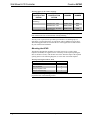
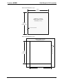
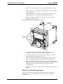
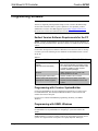
1
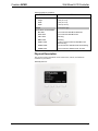
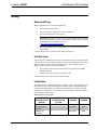
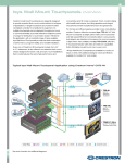
Crestron APAD Wall Mount LCD Controller Operations & Installation Guide This document was prepared and written by the Technical Documentation department at: Crestron Electronics, Inc. 15 Volvo Drive Rockleigh, NJ 07647 1-888-CRESTRON All brand names, product names and trademarks are the property of their respective owners. ©2006 Crestron Electronics, Inc. Crestron APAD Wall Mount LCD Controller Contents Wall Mount LCD Controller: APAD 1 Introduction ............................................................................................................................... 1 Features and Functions ................................................................................................ 1 Specifications .............................................................................................................. 2 Physical Description.................................................................................................... 3 Industry Compliance ................................................................................................... 6 Setup .......................................................................................................................................... 7 Network Wiring........................................................................................................... 7 Identity Code ............................................................................................................... 7 Installation ................................................................................................................... 7 Hardware Hookup ..................................................................................................... 11 Configuring the APAD.............................................................................................. 12 Setup Mode................................................................................................................ 12 Programming Software ............................................................................................................ 14 Earliest Version Software Requirements for the PC ................................................. 14 Programming with Crestron SystemBuilder.............................................................. 14 Programming with SIMPL Windows ........................................................................ 14 Programming with VisionTools Pro-e....................................................................... 16 Example Program ...................................................................................................... 16 Uploading and Upgrading........................................................................................................ 17 Establishing Communication..................................................................................... 17 Programs, Projects, and Firmware............................................................................. 17 Operation ................................................................................................................................. 18 Problem Solving ...................................................................................................................... 19 Troubleshooting......................................................................................................... 19 Check Network Wiring.............................................................................................. 19 Reference Documents................................................................................................ 20 Further Inquiries ........................................................................................................ 20 Future Updates .......................................................................................................... 21 Return and Warranty Policies .................................................................................................. 22 Merchandise Returns / Repair Service ...................................................................... 22 CRESTRON Limited Warranty................................................................................. 22 Operations & Installation Guide – DOC. 6455 Contents • i Crestron APAD Wall Mount LCD Controller Wall Mount LCD Controller: APAD Introduction Features and Functions • Stylish, affordable wall mount controller • Pleasing white-on-black LCD graphic display • Translucent white backlit “softkey” pushbuttons • Intuitive navigation wheel with “key click” audible feedback • Cresnet® communications — 2-Series compatible Graphic Display The white-on-black LCD display presents the user with a large amount of information in a small space. With graphical support for scrolling text, icons, and bargraphs, the APAD delivers an ideal user interface for controlling audio and a range of other possible functions throughout the home or office. Four "softkey" buttons beneath the display permit intuitive menu navigation and function selection. Nav Wheel The APAD's navigation wheel (Nav Wheel) enables easy navigation of menus, scrolling through lists of items and/or functions, and adjusting values that appear on the display. The built-in "key click" feature audibly enhances the Nav Wheel's natural feel, and the “soft” button to the right quickly executes the desired selection set by the Nav Wheel. A dedicated, programmable power button is also included for fast, easy power on/off control of system devices. Backlit Buttons The buttons on the APAD are translucent with adjustable white LED backlighting for a luxurious, luminous appearance and easy operation under low lighting conditions. Operations & Installation Guide – DOC. 6455 Wall Mount LCD Controller: APAD • 1 Wall Mount LCD Controller Crestron APAD True-Feedback Simplified connectivity using the Crestron® 4-wire Cresnet control bus makes installation a breeze. Fully bidirectional communications enables true-feedback for display of current status of audio, lighting, or climate control settings. Versatile Mounting Options Several mounting options are available for the APAD to facilitate a clean, attractive installation in any wall or similar flat surface. Specifications Specifications for the APAD are listed in the following table. APAD Specifications SPECIFICATION DETAILS LCD Display Display Type Transmissive LCD dot matrix Size 2.72 in (6.9 cm) wide x 1.44 in (3.7 cm) high Resolution 128 x 64 pixels Color Monochrome, white on black, invertible Illumination White LED backlit Controls Nav Wheel (1) Continuous turn rotary encoder; used to navigate menu, scroll through lists and adjust values. Functions (5) “softkey” pushbuttons, programmable, normally used to select menu functions. The pushbutton to the right of the nav wheel is normally used to execute a selected command.* Power (1) pushbutton, programmable, normally used to execute a power command* * All pushbuttons translucent, white backlit, dimmable Graphics Monochrome, white on black (invertible), supports dynamic text and icon graphics Audio Built-in speaker (rear) for key click sound Power Requirements Cresnet Power Usage 3 Watts (0.125 Amps @ 24 Volts DC) Default NET ID 2E Minimum 2-Series Control System Update File 3.155.0 or later Environmental Temperature 32 to 104° F (0 to 40° C) Humidity 10% to 90% RH (non-condensing) Enclosure Construction Injection-molded plastic, flush wall-mountable Faceplate Injection-molded plastic, white (Continued on next page) 2 • Wall Mount LCD Controller: APAD Operations & Installation Guide – DOC. 6455 Crestron APAD Wall Mount LCD Controller APAD Specifications (continued) SPECIFICATION DETAILS Dimensions Height 4.8 in (12.2 cm) Width 4.9 in (12.5 cm) Depth 1.94 in (4.93 cm) Weight 9.2 oz (257.6 gm) AVAILABLE ACCESSORIES BB-1000L Pre-Construction Wall Mount Back Box PMK-1000L Pre-Construction Wall Mount Kit TMK-1000L Trim Ring MMK-1000L Mud Ring WMKT-1000L Lectern or Post-Construction Wall Mount Kit with Trim Ring WMKM-1000L Post-Construction Wall Mount Kit with Mud Ring WMKB-1000L Post Construction Wall Mount Kit - Bracket Physical Description This section provides information on the connections, controls, and indicators available on your APAD. APAD Physical View Operations & Installation Guide – DOC. 6455 Wall Mount LCD Controller: APAD • 3 Wall Mount LCD Controller Crestron APAD APAD Overall Dimensions 4.9 in (12.5 cm) 1.94 in (4.93 cm) 4.8 in (12.2 cm) 0.59 in (1.50 cm) 3.74 in (9.50 cm) 0.43 in (1.09 cm) 0.33 in (0.83 cm) 1.67 in (4.27 cm) 0.62 in (1.57 cm) 3.58 in (9.08 cm) 3.95 in (10.03 cm) 4.16 in (10.56 cm) 0.43 in (1.09 cm) 4.06 in (10.30 cm) 0.78 in (1.96 cm) 3.36 in (8.53 cm) 4 • Wall Mount LCD Controller: APAD Operations & Installation Guide – DOC. 6455 Crestron APAD Wall Mount LCD Controller APAD Front and Rear Face (Bezel Removed) APAD Controls, Connectors, & Indicators # CONNECTORS, CONTROLS, & INDICATORS DESCRIPTION 1 Display Screen Programmable display shows pages, menus, and soft button functions of a project used to control one or more devices in a Cresnet system. 2 Reset Button Used alone to reset system defaults. When pressed while another soft button is pressed, APAD immediately goes into Setup mode. 3 Power Button Used to execute a power command to one or more devices in the system. 4 Nav Wheel Used to navigate menus, scroll through lists and adjust values shown on the display. 5 Soft Buttons Five programmable buttons used with the Nav Wheel to select the functions and parameters used to control devices in the system. Each button can be programmed to provide a different function on every page of a given project. 6 NET 24 Y Z G 7 Operations & Installation Guide – DOC. 6455 Speaker Four-position terminal block connector for data and power. Connects to Cresnet control network. An interface connector is provided. Pin 1 (24) Power Pin 2 (Y) Data Pin 3 (Z) Data Pin 4 (G) Ground Built-in transducer for key click sound. Wall Mount LCD Controller: APAD • 5 Wall Mount LCD Controller Crestron APAD Industry Compliance As of the date of manufacture, the APAD has been tested and found to comply with specifications for CE marking and standards per EMC and Radiocommunications Compliance Labelling. NOTE: This device complies with part 15 of the FCC rules. Operation is subject to the following two conditions: (1) this device may not cause harmful interference, and (2) this device must accept any interference received, including interference that may cause undesired operation. This equipment has been tested and found to comply with the limits for a Class B digital device, pursuant to part 15 of the FCC Rules. These limits are designed to provide reasonable protection against harmful interference in a residential installation. This equipment generates, uses and can radiate radio frequency energy and, if not installed and used in accordance with the instructions, may cause harmful interference to radio communications. However, there is no guarantee that interference will not occur in a particular installation. If this equipment does cause harmful interference to radio or television reception, which can be determined by turning the equipment off and on, the user is encouraged to try to correct the interference by one or more of the following measures: Reorient or relocate the receiving antenna. Increase the separation between the equipment and receiver. Connect the equipment into an outlet on a circuit different from that to which the receiver is connected. Consult the dealer or an experienced radio/TV technician for help. 6 • Wall Mount LCD Controller: APAD Operations & Installation Guide – DOC. 6455 Crestron APAD Wall Mount LCD Controller Setup Network Wiring When wiring the network, consider the following: • Use Crestron Certified Wire. • Use Crestron power supplies for Crestron equipment. • Provide sufficient power to the system. CAUTION: Insufficient power can lead to unpredictable results or damage to the equipment. Please use the Crestron Power Calculator to help calculate how much power is needed for the system (http://www.crestron.com/calculators). • For larger networks, use a Cresnet Hub/Repeater (CNXHUB) to maintain signal quality. For more details, refer to “Check Network Wiring” on page 19. Identity Code The Net ID of the APAD has been factory set to 2E. The Net IDs of multiple APAD devices in the same system must be unique. Net IDs can be changed from the “Setup Mode” on page 12 or from a personal computer (PC) via the Crestron Toolbox. When setting the Net ID, consider the following: • The Net ID of each unit must match an ID code specified in the SIMPL Windows program. • Each network device must have a unique Net ID. For more details, refer to the Crestron Toolbox help file. Installation The APAD installs simply and cleanly into existing or newly constructed walls, with an assortment of pre- and post-construction mounting options. All listed mounting options are provided separately from the actual APAD. Refer to the table after this paragraph for a complete list of mounting options and respective Installation Guides for the APAD LCD Controller. Mounting Options for the APAD PRECONSTRUCTION OPTION POSTCONSTRUCTION OPTION MODEL NUMBER DOCUMENT NUMBER Back Box Kit BB-1000L 6060 Pre-Construction Mount Kit PMK-1000L 6061 Mud Mount Kit (accessory) MMK-1000L 6062 (Continued on next page) Operations & Installation Guide – DOC. 6455 Wall Mount LCD Controller: APAD • 7 Wall Mount LCD Controller Crestron APAD Mounting Options for the APAD (continued) PRECONSTRUCTION OPTION POSTCONSTRUCTION OPTION MODEL NUMBER Trim Mount Kit (accessory) DOCUMENT NUMBER TMK-1000L 6063 Wall Mount Kit – Mud WMKM-1000L 6062 Wall Mount Kit – Trim WMKT-1000L 6063 Wall Mount Kit – Bracket * WMKB-1000L 6283 *One set of brackets is supplied with the APAD NOTE: Pre-construction refers to framed walls prior to hanging drywall. Post-construction refers to framed walls with drywall hung. The only tools required for the procedures presented here are masking tape (or equivalent), a gypsum board saw (or equivalent), and a #1 Phillips tip screwdriver. The following procedures are based on the use of the supplied screws and brackets for post-construction installation. Mounting the APAD The APAD is designed for mounting in a wall or lectern. Two overlay cutout templates (0V40087) are supplied. One is in the shape of the required opening; the other is similar to a frame, with the inner area of the frame the shape of the required opening. (Refer to the following diagrams.) Use the most convenient template. Mounting Parts Supplied with the APAD PART DESCRIPTION QUANTITY Screw #4-40 x 1-½”, Pan Head 4 Mounting Bracket 2 Overlay Template Cutout 1 Four-pin Connector Plug 1 NOTE: The following drawings are not to scale. Do not attempt to use them to prepare the hole in the mounting surface. 8 • Wall Mount LCD Controller: APAD Operations & Installation Guide – DOC. 6455 Crestron APAD Wall Mount LCD Controller APAD Cutout Dimensions (1 of 2) 4.17 in (10.60 cm) TEMPLATE - 0V40087 FOR LC–1000, CT–1000 OR APAD ( 1 OF 2 ) 4.27 in (10.85 cm) CUT ALONG THIS EDGE APAD Cutout Dimensions (2 of 2) TEMPLATE - 0V40087 FOR LC–1000, CT–1000 OR APAD ( 2 OF 2 ) CUT ALONG THIS EDGE 4.27 in (10.85 cm) 4.17 in (10.60 cm) Operations & Installation Guide – DOC. 6455 Wall Mount LCD Controller: APAD • 9 Wall Mount LCD Controller Crestron APAD 1. Locate an area on the wall that is free of studs and miscellaneous wiring. 2. Make a small hole near the middle of the designated site, and verify that the location is suitable. 3. Using masking tape (or equivalent), fasten the template to the wall; verify that the template is level, and trace the opening shape on the wall. 4. Remove the template, and then cut out and remove the traced shape to produce the required opening. APAD Mounting Example (Mounting Surface Not Shown) Mounting Brackets Mounting Screws 5. Connect the Cresnet cable, using the supplied mating connector, to the Cresnet port as described in “Hardware Hookup” on page 11. 6. Insert the mounting screws through the APAD front plate as shown and thread into the mounting brackets a few turns. 7. Insert the APAD into the mounting hole and tighten the screws evenly to bring the mounting brackets into contact with the back of the drywall. 8. Make sure the APAD is positioned squarely in the mounting hole, and then, using a #1 Phillips screwdriver, tighten the mounting screws slightly, about an additional 1/2 turn, to hold the unit securely in position. Do not overtighten screws. 9. Place the bezel in position over the unit. The bezel is held firmly in place by magnets. Removal from the Mounting Surface If it is necessary to remove the APAD after it has been installed, complete the following steps in the order provided. The only tool required is a #1 Phillips screwdriver. 10 • Wall Mount LCD Controller: APAD Operations & Installation Guide – DOC. 6455 Crestron APAD Wall Mount LCD Controller NOTE: If it becomes necessary to remove the APAD from the mounting surface, the original mounting brackets may fall into the wall and will have to be replaced. Additional brackets are available in the optional Wall Mount Kit – Bracket, Model Number WMKB-1000L. 1. Pull the bezel away from the APAD. 2. Loosen and remove the two screws that secure the top of the APAD to the mounting surface. 3. Loosen but do not remove the two screws that secure the bottom of the APAD to the mounting surface, and shift the APAD in the hole so the brackets will fall away from their top position on the mounting surface. 4. Pull the top portion of the APAD away from the mounting surface first and attempt to remove the unit from the opening with the brackets hanging from the bottom mounting screws. 5. If necessary, secure the attached cable before disconnecting it from the back of the APAD, to keep it from falling into the wall. Hardware Hookup NOTE: To prevent overheating, do not operate this product in an area that exceeds the environmental temperature range listed in the specifications table. Consideration must be given if installed in a closed or multi-unit rack assembly, inside a closed desk, or in a closed podium since the operating ambient temperature of these environments may be greater than the room ambient. Contact with thermal insulating materials should be avoided on all sides of the unit. Connecting the Device Make the necessary connections as called out in the illustration that follows this paragraph. Refer to “Network Wiring” on page 7 before attaching the 4-position terminal block connector (supplied). Apply power to the network after all connections have been made. Hardware Connections for the APAD Operations & Installation Guide – DOC. 6455 Wall Mount LCD Controller: APAD • 11 Wall Mount LCD Controller Crestron APAD Configuring the APAD Project not Found Screen MAIN MENU Prior to normal operation, it is necessary to configure the unit using a series of setup screens. If the project for the APAD has not been loaded prior to configuring the APAD, the screen shown to the left is displayed instead of the MAIN MENU. You can choose to load the project at this time (refer to “Uploading and Upgrading” on page 17), or follow the screen instruction and press any button to enter the Setup Mode. If the APAD project has already been loaded, the MAIN MENU for configuring the APAD, shown to the left, appears when any button is pressed and held (approximately five seconds) when power is applied. Note that holding any of the soft buttons for more than 10 seconds while going into setup mode will reset the brightness and contrast to their default levels. The MAIN MENU displays three soft button choices: About, Setup, and Save and Exit. ABOUT Screen Selecting About displays an information screen that shows the firmware, project name, and version number. Selecting Setup displays the Setup screen (Refer to “Setup Mode,” below) that provides all the parameters that are used to configure the APAD. The Save and Exit selection is used after performing all setup functions to save the configuration and exit to normal operation. Load in Progress Screen If you choose to load the project at this time, the screen displays a progress bar as the project is loaded (shown to the left). Setup Mode Screen Setup Mode Setup Mode can be entered from the Main Menu, as stated above, or, if the APAD has not yet been installed, by pressing and holding any button when power is applied. If the unit is installed and power is already applied, the easiest method is to remove the bezel, press and hold any button, and press the Reset button; the unit immediately enters Setup Mode. In the Setup Mode, use the Nav Wheel to scroll through the menu options, and then press the soft button to the right to select the option. Press the Back soft button to return to the Main Menu. The following paragraphs describe each of the setup options in the order listed in the menu. Cresnet ID Screen Cresnet ID Use the Nav Wheel to select the desired ID number, from 03 to FE, in least significant digit steps (e.g., 03, 04, 05), or use the << and >> soft buttons to change the number in most significant digit steps (e.g., 03, 13, 23). Press the Default soft button to select the default ID value (2E), press the Ok soft button to accept the selection and return to the Setup Mode screen. 12 • Wall Mount LCD Controller: APAD Operations & Installation Guide – DOC. 6455 Crestron APAD LCD Brightness Wall Mount LCD Controller LCD Brightness Use the Nav Wheel to select the desired brightness percentage value, from 01 to 99, in single digit steps (01, 02, 03, etc.), or use the << and >> soft buttons to change the number in most significant digit steps (10, 20, 30, etc.). Note that holding any of the soft buttons for more than 10 seconds while going into setup mode will reset the brightness to the default (22%). Press the Default soft button to return to the default setting; press Ok to accept the new setting and return to the Setup Mode screen. Screen Invert Screen Invert Use the soft buttons to turn screen inversion on or off. (“Off” is normal appearance – white text on black screen. “On” is inverted appearance – black text on white screen.) Press the Default soft button to return to the default setting; press Ok to accept the new setting and return to the Setup Mode screen. LCD Contrast LCD Contrast Use the Nav Wheel to select the desired LCD contrast percentage value, from 01 to 99, in single-digit steps (01, 02, 03, etc.), or use the << and >> soft buttons to change the number in most significant digit steps (10, 20, 30, etc.). Note that two contrast settings are required: one for invert on, and one for invert off. Note that holding any of the soft buttons for more than 10 seconds while going into setup mode will reset the contrast to the defaults (non-inverted contrast 72%; inverted contrast 66%). Press the Default soft button to return to the default setting; press Ok to accept the new setting and return to the Setup Mode screen. Key Backlight Key Backlight Use the Nav Wheel to select the desired key backlight percentage value, from 01 to 99, in single-digit steps (01, 02, 03, etc.), or use the << and >> soft buttons to change the number in most significant digit steps (10, 20, 30, etc.). Press the Default soft button to return to the default setting (30%); press Ok to accept the new setting and return to the Setup Mode screen. Standby Standby Use the Nav Wheel to select the desired standby minutes, from 0 to 120, in singleminute increments, or use the << and >> soft buttons to change the number in tenminute increments (10, 20, 30, etc.). Press the Default soft button to return to the default setting (10 minutes); press Ok to accept the new setting and return to the Setup Mode screen. Key Click Key Click Use the ON and OFF soft buttons to turn the Key Click feature on and off (default is off). Press the Default soft button to return to the default setting; press Ok to accept the new setting and return to the Setup Mode screen. Operations & Installation Guide – DOC. 6455 Wall Mount LCD Controller: APAD • 13 Wall Mount LCD Controller Crestron APAD Programming Software Have a question or comment about Crestron software? Answers to frequently asked questions (FAQs) can be viewed in the Online Help section of the Crestron website. To post a question or view questions you have submitted to Crestron’s True Blue Support, log in at http://support.crestron.com. First-time users will need to establish a user account. Earliest Version Software Requirements for the PC NOTE: Crestron recommends that you use the latest software to take advantage of the most recently released features. The latest software is available from the Crestron website. Crestron has developed an assortment of Windows-based software tools to develop a Cresnet system. The following are the minimum recommended software versions for the PC: Software TASK REQUIRED SOFTWARE VERSION Simplify programming with wizards (optional but recommended) Crestron SystemBuilder™ version 3.0 or later with SystemBuilder Templates version 3.0 or later; Refer to software release notes or Crestron website for other required Crestron software packages Program SIMPL Windows 2.07.17 or later, with Library Update 377 or later Upload program and firmware Crestron Toolbox 1.02.17 or later Create custom LCD screens and page flips for custom programs Vision Tools® Pro-e version 3.5 or later; Requires Crestron Database version 18.0 or later Programming with Crestron SystemBuilder Crestron SystemBuilder is the easiest method of programming a Crestron system. For additional details, download SystemBuilder from the Crestron website and examine the extensive help file. For lower level control and additional programming flexibility, use SIMPL Windows. Programming with SIMPL Windows NOTE: While SIMPL Windows can be used to program the APAD, it is recommended to use SystemBuilder for configuring a system that contains the APAD. SIMPL Windows is Crestron’s premier software for programming Crestron control systems. It is organized into two separate, but equally important “Managers.” 14 • Wall Mount LCD Controller: APAD Operations & Installation Guide – DOC. 6455 Crestron APAD Configuration Manager Wall Mount LCD Controller Configuration Manager is the view where programmers “build” a Crestron control system by selecting hardware from the Device Library. • To incorporate the APAD into the system, drag the APAD from the Wired Keypads folder of the Device Library and drop it in the System Views. Locating the APAD in the Device Library • The system tree of the control system displays the device in the appropriate slot with a default Net ID as shown in the following illustration. C2Net Device, Slot 9 • Additional APAD devices are assigned different Net ID numbers as they are added. • If necessary, double click a device to open the “Device Settings” window and change the Net ID, as shown in the following figure. Operations & Installation Guide – DOC. 6455 Wall Mount LCD Controller: APAD • 15 Wall Mount LCD Controller Crestron APAD “APAD Device Settings” Window • Programming Manager The ID code specified in the SIMPL Windows program must match the Net ID of each unit. Programming Manager is the view where programmers "program" a Crestron control system by assigning signals to symbols. The symbol can be viewed by double clicking on the icon or dragging it into Detail View. A description for each signal in the symbol is described in the SIMPL Windows help file (F1). Programming with VisionTools Pro-e The APAD LCD screens should be created in VisionTools Pro-e to allow selection of functions, and control of system devices. Note that the APAD design permits the six buttons to be programmed individually per project or for each page in a project. The result is almost limitless functionality, with real time feedback of commands. Example Program An example program for the APAD is available from the Crestron website (http://www.crestron.com/exampleprograms). 16 • Wall Mount LCD Controller: APAD Operations & Installation Guide – DOC. 6455 Crestron APAD Wall Mount LCD Controller Uploading and Upgrading Crestron recommends using the latest programming software and that each device contains the latest firmware to take advantage of the most recently released features. However, before attempting to upload or upgrade, it is necessary to establish communication. Establishing Communication Use Crestron Toolbox for communicating with the APAD; refer to the Crestron Toolbox help file for details. There is a single method of communication: indirect serial communication. Indirect Serial Communication PC RUNNING CRESTRON TOOLBOX SERIAL, ETHERNET, OR USB CONTROL SYSTEM CRESNET APAD • The APAD connects to the control system via Cresnet. • Establish communications between the PC and the control system as described in the latest version of the 2-Series Reference Guide (Doc. 6256). Programs, Projects, and Firmware • Display the network device tree (Tools | Network Device Tree); to show all network devices connected to the control system. Right-click on the APAD Cresnet ID to display actions that can be performed on the APAD, such as: ⇒ Upgrade firmware ⇒ Change Net ID • Upload the SIMPL Windows file to the control system using SIMPL Windows or Crestron Toolbox. • Upload the VisionTools Pro-e file to the APAD using VisionTools Pro-e or the Crestron Toolbox. • Upgrade APAD firmware via Crestron Toolbox. ⇒ Establish serial communications with the APAD. ⇒ Select Functions | Firmware… to upgrade the APAD firmware. For details on uploading and upgrading, refer to the SIMPL Windows help file, VisionTools Pro-e help file, or the Crestron Toolbox help file. Operations & Installation Guide – DOC. 6455 Wall Mount LCD Controller: APAD • 17 Wall Mount LCD Controller Crestron APAD Operation Operation of the APAD is determined by the program developed for the system in which it is used. 18 • Wall Mount LCD Controller: APAD Operations & Installation Guide – DOC. 6455 Crestron APAD Wall Mount LCD Controller Problem Solving Troubleshooting The following table provides corrective action for possible trouble situations. If further assistance is required, please contact a Crestron customer service representative. APAD Troubleshooting TROUBLE Project cannot be uploaded to keypad: 1. Screen is black. POSSIBLE CAUSE(S) CORRECTIVE ACTION 2. Communications error. APAD is powered down. Incorrect COM port specified. Verify that power is supplied to the APAD. Verify upload preferences is set to the COM port being used to communicate to the control system. 3. Checking panel type error. Incorrect NET ID setting. Verify that panel NET ID matches the NET ID specified during upload. Refer to "Uploading and Upgrading" in this guide. Check the cable for errors or poor connections. Wrong screens appear on LCD. LCD is dark or too light. Problem with cable between control system and APAD. Screens were not uploaded. LCD brightness or contrast is improperly set. Upload screens as described in the help files found in VT Pro-e. Hold down any of the soft buttons for more than 10 seconds as power is applied. The LCD brightness and contrast are set to their default values. Check Network Wiring Use the Right Wire In order to ensure optimum performance over the full range of your installation topology, Crestron Certified Wire, and only Crestron Certified Wire, may be used. Failure to do so may incur additional charges if support is required to identify performance deficiencies because of using improper wire. Calculate Power CAUTION: Use only Crestron power supplies for Crestron equipment. Failure to do so could cause equipment damage or void the Crestron warranty. CAUTION: Provide sufficient power to the system. Insufficient power can lead to unpredictable results or damage to the equipment. Please use the Crestron Power Calculator to help calculate how much power is needed for the system (http://www.crestron.com/calculators). When calculating the length of wire for a particular Cresnet run, the wire gauge and the Cresnet power usage of each network unit to be connected must be taken into consideration. Use Crestron Certified Wire only. If Cresnet units are to be daisychained on the run, the Cresnet power usage of each network unit to be daisy-chained must be added together to determine the Cresnet power usage of the entire chain. If the unit is a home-run from a Crestron system power supply network port, the Cresnet Operations & Installation Guide – DOC. 6455 Wall Mount LCD Controller: APAD • 19 Wall Mount LCD Controller Crestron APAD power usage of that unit is the Cresnet power usage of the entire run. The wire gauge and the Cresnet power usage of the run should be used in the following equation to calculate the cable length value on the equation’s left side. Cable Length Equation L< 40,000 RxP Where: L = Length of run (or chain) in feet. 2 R = 6 Ohms (Crestron Certified Wire: 18 AWG (0.75 MM )) P = Cresnet power usage of entire run (or chain). Make sure the cable length value is less than the value calculated on the right side of the equation. For example, a Cresnet run drawing 20 watts should not have a length of run more than 333 feet. NOTE: All Crestron certified Cresnet wiring must consist of two twisted pairs. One twisted pair is the +24V conductor and the GND conductor, and the other twisted pair is the Y conductor and the Z conductor. Strip and Tin Wire When daisy-chaining Cresnet units, strip the ends of the wires carefully to avoid nicking the conductors. Twist together the ends of the wires that share a pin on the network connector, and tin the twisted connection. Apply solder only to the ends of the twisted wires. Avoid tinning too far up the wires or the end becomes brittle. Insert the tinned connection into the Cresnet connector and tighten the retaining screw. Repeat the procedure for the other three conductors. Add Hubs For larger networks (i.e., greater than 28 network devices), it may become necessary to add a Cresnet Hub/Repeater (CNXHUB) to maintain signal quality throughout the network. Also, for networks with lengthy cable runs, it may be necessary to add a Hub/Repeater after only 20 devices. Reference Documents The latest version of all documents mentioned within the guide can be obtained from the Crestron website (http://www.crestron.com/manuals). This link will provide a list of product manuals arranged in alphabetical order by model number. List of Related Reference Documents DOCUMENT TITLE 2-Series Control Systems Reference Guide CAT5 Reference Guide RoomView Reference Guide Further Inquiries If you cannot locate specific information or have questions after reviewing this guide, please take advantage of Crestron's award winning customer service team by calling the Crestron corporate headquarters at 1-888-CRESTRON [1-888-273-7876]. For assistance in your local time zone, refer to the Crestron website (http://www.crestron.com/) for a listing of Crestron worldwide offices. You can also log onto the online help section of the Crestron website to ask questions about Crestron products. First-time users will need to establish a user account to fully benefit from all available features. 20 • Wall Mount LCD Controller: APAD Operations & Installation Guide – DOC. 6455 Crestron APAD Wall Mount LCD Controller Future Updates As Crestron improves functions, adds new features, and extends the capabilities of the APAD, additional information may be made available as manual updates. These updates are solely electronic and serve as intermediary supplements prior to the release of a complete technical documentation revision. Check the Crestron website periodically for manual update availability and its relevance. Updates are identified as an “Addendum” in the Download column. Operations & Installation Guide – DOC. 6455 Wall Mount LCD Controller: APAD • 21 Wall Mount LCD Controller Crestron APAD Return and Warranty Policies Merchandise Returns / Repair Service 1. No merchandise may be returned for credit, exchange, or service without prior authorization from CRESTRON. To obtain warranty service for CRESTRON products, contact an authorized CRESTRON dealer. Only authorized CRESTRON dealers may contact the factory and request an RMA (Return Merchandise Authorization) number. Enclose a note specifying the nature of the problem, name and phone number of contact person, RMA number, and return address. 2. Products may be returned for credit, exchange, or service with a CRESTRON Return Merchandise Authorization (RMA) number. Authorized returns must be shipped freight prepaid to CRESTRON, 6 Volvo Drive, Rockleigh, N.J. or its authorized subsidiaries, with RMA number clearly marked on the outside of all cartons. Shipments arriving freight collect or without an RMA number shall be subject to refusal. CRESTRON reserves the right in its sole and absolute discretion to charge a 15% restocking fee, plus shipping costs, on any products returned with an RMA. 3. Return freight charges following repair of items under warranty shall be paid by CRESTRON, shipping by standard ground carrier. In the event repairs are found to be non-warranty, return freight costs shall be paid by the purchaser. CRESTRON Limited Warranty CRESTRON ELECTRONICS, Inc. warrants its products to be free from manufacturing defects in materials and workmanship under normal use for a period of three (3) years from the date of purchase from CRESTRON, with the following exceptions: disk drives and any other moving or rotating mechanical parts, pan/tilt heads and power supplies are covered for a period of one (1) year; touchscreen display and overlay components are covered for 90 days; batteries and incandescent lamps are not covered. This warranty extends to products purchased directly from CRESTRON or an authorized CRESTRON dealer. Purchasers should inquire of the dealer regarding the nature and extent of the dealer's warranty, if any. CRESTRON shall not be liable to honor the terms of this warranty if the product has been used in any application other than that for which it was intended, or if it has been subjected to misuse, accidental damage, modification, or improper installation procedures. Furthermore, this warranty does not cover any product that has had the serial number altered, defaced, or removed. This warranty shall be the sole and exclusive remedy to the original purchaser. In no event shall CRESTRON be liable for incidental or consequential damages of any kind (property or economic damages inclusive) arising from the sale or use of this equipment. CRESTRON is not liable for any claim made by a third party or made by the purchaser for a third party. CRESTRON shall, at its option, repair or replace any product found defective, without charge for parts or labor. Repaired or replaced equipment and parts supplied under this warranty shall be covered only by the unexpired portion of the warranty. Except as expressly set forth in this warranty, CRESTRON makes no other warranties, expressed or implied, nor authorizes any other party to offer any warranty, including any implied warranties of merchantability or fitness for a particular purpose. Any implied warranties that may be imposed by law are limited to the terms of this limited warranty. This warranty statement supersedes all previous warranties. Trademark Information All brand names, product names, and trademarks are the sole property of their respective owners. Windows is a registered trademark of Microsoft Corporation. Windows95/98/Me/XP and WindowsNT/2000 are trademarks of Microsoft Corporation. 22 • Wall Mount LCD Controller: APAD Operations & Installation Guide – DOC. 6455 Crestron APAD Wall Mount LCD Controller This page intentionally left blank Operations & Installation Guide – DOC. 6455 Wall Mount LCD Controller: APAD • 23 Crestron Electronics, Inc. 15 Volvo Drive Rockleigh, NJ 07647 Tel: 888.CRESTRON Fax: 201.767.7576 www.crestron.com Operations & Installation Guide – DOC. 6455 (2014585) 04.06 Specifications subject to change without notice.