1
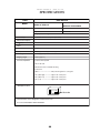
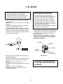
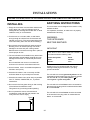
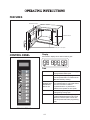
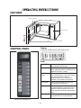
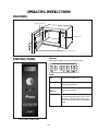
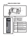
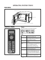
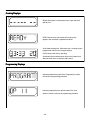
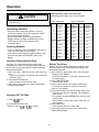
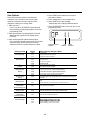
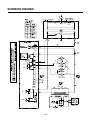
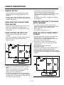
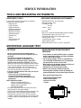
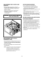
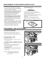
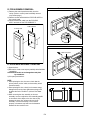
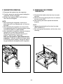
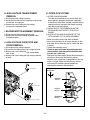
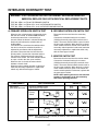
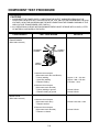
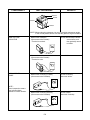
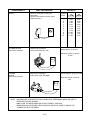
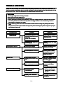
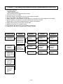
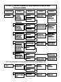
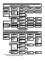
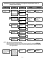
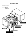
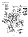
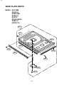
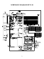
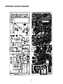
Microwave Oven
Service Manual
RS511P
RS511MB
RCS10MPA
RCS511A
RCS10MPSA
RFS511G
RFS12MPSA
URS511MB
RFS12G
URS511P
URCS511A
RFS511SW2A
CAUTION
BEFORE SERVICING THE UNIT, READ THE
SAFETY PRECAUTIONS IN THIS MANUAL.
SAFETY PRECAUTIONS
This device is to be serviced only by properly qualified service personnel.
Consult the service manual for proper service procedures to assure continued safety operation and for precautions to be
taken to avoid possible exposure to excessive microwave energy.
PRECAUTIONS TO BE OBSERVED BEFORE AND
DURING SERVICING TO AVOID POSSIBLE
EXPOSURE TO EXCESSIVE MICROWAVE ENERGY
A) Do not operate or allow the oven to be operated with the door open.
B) Make the following safety checks on all ovens to be serviced before activating the magnetron or other
microwave source, and make repairs as necessary; (1) interlock operation, (2) proper door closing, (3)
seal and sealing surfaces (arcing, wear, and other damage), (4) damage to or loosening of hinges and
latches, (5) evidence of dropping or abuse.
C) Before turning on microwave power for any service test or inspection within the microwave generating
compartments, check the magnetron, wave guide or transmission line, and cavity for proper alignment,
integrity, and connections.
D) Any defective or misadjusted components in the interlock, monitor, door seal, and microwave generation
and transmission systems shall be repaired, replaced, or adjusted by procedures described in this manual
before the oven is released to the owner.
E) A microwave leakage check to verify compliance with the Federal Performance Standard should be
performed on each oven prior to release to the owner.
CONTENTS
(Page)
SAFETY PRECAUTIONS - - - - - - - - - - - - - - - - - - - - - - - - - - - - - - - - - - - - - - - - - - - - - - - - - - - - - - - - - - - - - - - - - - - - - Inside front cover
SPECIFICATIONS - - - - - - - - - - - - - - - - - - - - - - - - - - - - - - - - - - - - - - - - - - - - - - - - - - - - - - - - - - - - - - - - - - - - - - - - - - - - - - - - - - - - - - - - - - - - - - - - - - - - - 1-1
CAUTIONS - - - - - - - - - - - - - - - - - - - - - - - - - - - - - - - - - - - - - - - - - - - - - - - - - - - - - - - - - - - - - - - - - - - - - - - - - - - - - - - - - - - - - - - - - - - - - - - - - - - - - - - - - - - - - - 2-1
INSTALLATIONS - - - - - - - - - - - - - - - - - - - - - - - - - - - - - - - - - - - - - - - - - - - - - - - - - - - - - - - - - - - - - - - - - - - - - - - - - - - - - - - - - - - - - - - - - - - - - - - - - - - - - - 3-1
OPERATING INSTRUCTIONS - - - - - - - - - - - - - - - - - - - - - - - - - - - - - - - - - - - - - - - - - - - - - - - - - - - - - - - - - - - - - - - - - - - - - - - - - - - - - - - - - - - - 4-1
COOKING DISPLAYS - - - - - - - - - - - - - - - - - - - - - - - - - - - - - - - - - - - - - - - - - - - - - - - - - - - - - - - - - - - - - - - - - - - - - - - - - - - - - - - - - - - - - - - - - - - - - - - - - - - - - - - - - 4-6
PROGRAMMING DISPLAYS - - - - - - - - - - - - - - - - - - - - - - - - - - - - - - - - - - - - - - - - - - - - - - - - - - - - - - - - - - - - - - - - - - - - - - - - - - - - - - - - - - - - - - - - - - - - - - - - 4-6
OPERATION- - - - - - - - - - - - - - - - - - - - - - - - - - - - - - - - - - - - - - - - - - - - - - - - - - - - - - - - - - - - - - - - - - - - - - - - - - - - - - - - - - - - - - - - - - - - - - - - - - - - - - - - - - - - - - - - - - - - - - - 4-7
PROGRAMMING - - - - - - - - - - - - - - - - - - - - - - - - - - - - - - - - - - - - - - - - - - - - - - - - - - - - - - - - - - - - - - - - - - - - - - - - - - - - - - - - - - - - - - - - - - - - - - - - - - - - - - - - - - - - - - - - 4-8
SCHEMATIC DIAGRAM - - - - - - - - - - - - - - - - - - - - - - - - - - - - - - - - - - - - - - - - - - - - - - - - - - - - - - - - - - - - - - - - - - - - - - - - - - - - - - - - - - - - - - - - - - - - - - - - - - - - 4-10
CIRCUIT DESCRIPTION - - - - - - - - - - - - - - - - - - - - - - - - - - - - - - - - - - - - - - - - - - - - - - - - - - - - - - - - - - - - - - - - - - - - - - - - - - - - - - - - - - - - - - - - - - - - - - - - - - - 4-11
SERVICE INFORMATION - - - - - - - - - - - - - - - - - - - - - - - - - - - - - - - - - - - - - - - - - - - - - - - - - - - - - - - - - - - - - - - - - - - - - - - - - - - - - - - - - - - - - - - - - - 5-1
TOOLS AND MEASURING INSTRUMENTS - - - - - - - - - - - - - - - - - - - - - - - - - - - - - - - - - - - - - - - - - - - - - - - - - - - - - - - - - - - - - - - - - - - - - - - - - - - 5-1
MICROWAVE LEAKAGE TEST - - - - - - - - - - - - - - - - - - - - - - - - - - - - - - - - - - - - - - - - - - - - - - - - - - - - - - - - - - - - - - - - - - - - - - - - - - - - - - - - - - - - - - - - - - - - 5-1
MEASUREMENT OF MICROWAVE POWER OUTPUT - - - - - - - - - - - - - - - - - - - - - - - - - - - - - - - - - - - - - - - - - - - - - - - - - - - - - - - - - - - 5-3
DISASSEMBLY AND ADJUSTMENT - - - - - - - - - - - - - - - - - - - - - - - - - - - - - - - - - - - - - - - - - - - - - - - - - - - - - - - - - - - - - - - - - - - - - - - - - - - - - - - - - - - - - 5-3
INTERLOCK CONTINUITY TEST- - - - - - - - - - - - - - - - - - - - - - - - - - - - - - - - - - - - - - - - - - - - - - - - - - - - - - - - - - - - - - - - - - - - - - - - - - - - - - - - - - - - - - - - - - 5-7
COMPONENT TEST PROCEDURE - - - - - - - - - - - - - - - - - - - - - - - - - - - - - - - - - - - - - - - - - - - - - - - - - - - - - - - - - - - - - - - - - - - - - - - - - - - - - - - - - - - - - - 5-8
TROUBLE SHOOTING - - - - - - - - - - - - - - - - - - - - - - - - - - - - - - - - - - - - - - - - - - - - - - - - - - - - - - - - - - - - - - - - - - - - - - - - - - - - - - - - - - - - - - - - - - - - - - - - - - - - - - 5-11
EXPLODED VIEW - - - - - - - - - - - - - - - - - - - - - - - - - - - - - - - - - - - - - - - - - - - - - - - - - - - - - - - - - - - - - - - - - - - - - - - - - - - - - - - - - - - - - - - - - - - - - - - - - - - - - 6-1
SCHEMATIC DIAGRAM OF P.C.B. - - - - - - - - - - - - - - - - - - - - - - - - - - - - - - - - - - - - - - - - - - - - - - - - - - - - - - - - - - - - - - - - - - - - - - - - - - - - - - 7-1
PRINTED CIRCUIT BOARD - - - - - - - - - - - - - - - - - - - - - - - - - - - - - - - - - - - - - - - - - - - - - - - - - - - - - - - - - - - - - - - - - - - - - - - - - - - - - - - - - - - - - - - - - - - - - - - - - 7-2
SPECIFICATIONS
SPECIFICA
SPECIFICATIONS
ITEM
MODEL
Power Requirement
DESCRIPTION
RS511P / RS511MB
URS511MB / URS511P
RCS511A / RFS511G
URCS511A / RFS511SW2A
230 Volts AC 50 Hz
240 Volts AC 50 Hz
1,60
, 0 Watts
1,70
, 0 Watts
Single phase, 3 wire grounded
Power Output
1,100 Watts full microwave power (IEC 60705)
Microwave Frequency
2,450 MHz
Magnetron
2M282
Timer
0 ~ 60 min.
Outside Dimensions
21 3/4” (W) x 14 1/4” (H) x 17 7/8”(D)
Cavity Dimensions
14 1/4” (W) x 8 7/8” (H) x 16 3/8”(D)
Net Weight
51 lbs (approx.)
Shipping weight
58 lbs (approx.)
Control Complement
Touch Control System
Clock : 00 ~ 60
Microwave Power for Variable Cooking
Power level
HIGH -------------------------------Full power throughout the cooking time
70% (Med.-High)----------------approx. 70% of Full power
50% (Med.-Low) ---------------approx. 50% of Full power
20% (Low) -----------------------approx. 20% of Full power
Nameplate Location
Back side
This microwave oven is designed for commercial use only.
It is not recommended for built-in Installation.
SPECIFICATIONS
1-1
CAUTIONS
Unlike other appliances, the microwave oven is
high-voltage and high-current equipment.
Though it is free from danger in ordinary use,
extreme care should be taken during repair.
MICROWAVE RADIATION
Personnel should not be exposed to the
microwave energy which may radiate from the
magnetron or other microwave generating
device if it is improperly used or connection.
All input and output microwave connections,
waveguide, flange, and gasket must be secure
never operate the device without a microwave
energy absorbing load attached.
Never look into an open waveguide or antenna
while the device is energized.
¥ DO NOT operate on a 2-wire extension cord during
repair and use.
¥ NEVER TOUCH any oven components or wiring during
operation.
¥ BEFORE TOUCHING any parts of the oven, always
remove the power plug from the outlet.
¥ For about 30 seconds after the oven stops, an electric
charge remains in the high voltage capacitor. When
replacing or checking, you must discharge the high
voltage capacitor by shorting across the two terminals
with an insulated screwdriver.
¥ Proper operation of the microwave oven requires that
the magnetron be assembled to the waveguide and
cavity. Never operate the magnetron unless it is
properly installed.
¥ Be sure that the magnetron gasket is properly
installed around the dome of the tube whenever
installing the magnetron.
ANTENNA
Gasket
COOLING FIN
FILAMENT
TERMINALS
MAGNETRON
CHASSIS GROUND
MAGNETRON
¥ Remove your watches whenever working close to or
replacing the Magnetron.
¥ DO NOT touch any parts of the control panel circuit. A
resulting static electric discharge may damage this
P.C.B.
¥ NEVER operate the oven with no load.
¥ NEVER injure the door seal and front plate of the oven
cavity.
¥ NEVER put iron tools on the magnetron.
¥ NEVER put anything into the latch hole and the
interlock switches area.
THE OVEN IS TO BE SERVICED ONLY
BY PROPERLY QUALIFIED SERVICE
PERSONNEL.
2-1
INSTALLATIONS
BEFORE YOU BEGIN, READ THE FOLLOWING INSTRUCTIONS COMPLETELY AND CAREFULLY.
INSTALLING
EARTHING INSTRUCTIONS
1. Empty the microwave oven and clean inside it with
a soft, damp cloth. Check for damage such as
misaligned door, damage around the door or dents
inside the cavity or on the exterior.
This microwave oven is designed to be used in a fully
earthed condition.
It is imperative, therefore, to make sure it is properly
earthed before servicing
2. Put the oven on a counter, table, or shelf that is
strong enough to hold the oven and the food and
utensils you put in it. (The control panel side of the
oven is the heavy side. Use care when handling.)
WARNINGTHIS APPLIANCE
MUST BE EARTHED
3. Do not block the vent and the air intake openings.
Blocking vent or air intake openings can cause
damage to the oven and poor cooking results.
Make sure the microwave oven legs are in place to
ensure proper air flow.
IMPORTANT
The wires in this mains lead are colored in
accordance with the following code:
4. The oven should not be installed in any area where
heat and steam are generated, because they may
damage the electronic or mechanical parts of the
unit.
Do not install the oven next to a conventional
surface unit or above a conventional wall oven.
Green-and-yellow:
Blue:
Brown:
Earth
Neutral
Live
As the colors of the wires in the mains lead of this
appliance may not correspond with the colored
markings identifying the terminals in your plug,
proceed as follows.
5. Use microwave oven in an ambient temperature
less than 104°F(40°C).
6. Place the microwave oven on a sturdy and flat
surface at least 10 cm(4 inches) from the wall.
The wire which is colored green-and-yellow must be
connected to the terminal in the plug which is marked
with the letter E or by the earth symbol ( ) or
colored green or green-and-yellow.
7. Place the microwave oven as far away as possible
from TV, RADIO, COMPUTER, etc., to prevent
interference.
The wire which is colored blue must be connected to
the terminal in the plug which is marked with the letter
N or colored black.
8. Do not touch the front glass during or after cooking
of the Grill and Combination mode.
This glass is very hot during heater operating.
9. Do not operate the oven at microwave and
combination mode with Grill rack placed in the
cavity when the oven is empty.
The wire which is colored brown must be connected
to the terminal in the plug which is marked with the
letter L or colored red.
10cm
3-1
FEATURES
Window Door Screen
Electronic Control
Safety Door Lock System
CONTROL PANEL
Display
Some items in display can be seen but will not glow.
Pads
TIME ENTRY
Pads 1-0
HOLD 0%,
DEFROST 20%,
MEDUIM 50%,
MED-HI 70%
STOP/RESET
START
RS511P / URS511P
4-1
Use to enter heating time without changing
preprogrammed number pads.
Use to begin heating with preprogrammed
times and power levels or to enter times for
“Manual Time Entry” cooking.
Use to select power level. Oven can heat at
full or reduced power. If oven power level is
set to 0% oven does not heat for
programmed time. If no power level is
selected, oven operates at 100% power.
Use to exit programming mode and stop
cooking during cooking cycle.
Use to start “Manual Time Entry” program
or restart interrupted cooking cycle. Use to
advance to next user option. Use to save
times and power levels when programming
pads.
FEATURES
Window Door Screen
Electronic Control
Safety Door Lock System
CONTROL PANEL
Display
Some items in display can be seen but will not glow.
Pads
TIME ENTRY
Pads 1-0
POWER
LEVEL
STOP/RESET
START
QTY2x
RCS511A / URCS511A
4-2
Use to enter heating time without changing
preprogrammed number pads.
Use to begin heating with preprogrammed
times and power levels or to enter times for
“Manual Time Entry” cooking.
Use to select power level. Oven can heat at
full or reduced power. If oven power level is
set to 0% oven does not heat for
programmed time. If no power level is
selected, oven operates at 100% power.
Use to exit programming mode and stop
cooking during cooking cycle.
Use to start “Manual Time Entry” program
or restart interrupted cooking cycle. Use to
advance to next user option. Use to save
times and power levels when programming
pads.
Use to automatically increase the
programmed time for double quantities.
FEATURES
Window Door Screen
Electronic Control
Safety Door Lock System
CONTROL PANEL
Display
Some items in display can be seen but will not glow.
Pads
DIAL
Use to enter cooking time.
QUICK SET
Use to begin heating with preprogrammed
times and power levels.
70%,
50%,
DEFROST
Use to select power level. Oven can heat at
full or reduced power.
START
Use to start “Manual Time Entry” program
or restart interrupted cooking cycle. Use to
advance to next user option. Use to save
times and power levels when programming
pads.
8
9
0
RCS511MB / URS511MB
4-3
FEATURES
Window Door Screen
Electronic Control
Safety Door Lock System
CONTROL PANEL
Display
Some items in display can be seen but will not glow.
Pads
TIME ENTRY
Pads 1-0
HOLD 0%,
DEFROST 20%,
MEDUIM 50%,
MED-HI 70%
STOP/RESET
START
RFS511SW2A
4-4
Use to enter heating time without changing
preprogrammed number pads.
Use to begin heating with preprogrammed
times and power levels or to enter times for
“Manual Time Entry” cooking.
Use to select power level. Oven can heat at
full or reduced power. If oven power level is
set to 0% oven does not heat for
programmed time. If no power level is
selected, oven operates at 100% power.
Use to exit programming mode and stop
cooking during cooking cycle.
Use to start “Manual Time Entry” program
or restart interrupted cooking cycle. Use to
advance to next user option. Use to save
times and power levels when programming
pads.
OPERATING INSTRUCTIONS
FEATURES
Window Door Screen
Electronic Control
Safety Door Lock System
CONTROL PANEL
TIME
POWER
ENTRY LEVEL
-
Display
Some items in display can be seen but will not glow.
QTY
2X
Pads
+
8
9
TIME ENTRY
Use to enter heating time without changing
preprogrammed number pads.
Pads 1-0
Use to begin heating with preprogrammed
times and power levels or to enter times for
“Manual Time Entry” cooking.
DIAL
Use to enter times for “Manual Time Entry”
cooking.
POWER
LEVEL
Use to select power level. Oven can heat at
full or reduced power. If oven power level is
set to 0% oven does not heat for
programmed time. If no power level is
selected, oven operates at 100% power.
STOP/RESET
Use to exit programming mode and stop
cooking during cooking cycle.
START
Use to start “Manual Time Entry” program
or restart interrupted cooking cycle. Use to
advance to next user option. Use to save
times and power levels when programming
pads.
QTY2x
Use to automatically increase the
programmed time for double quantities.
0
RFS511G
4-5
Cooking Displays
Shows when power is connected to oven. Open and close
door to clear.
READY shows when oven control will accept entries.
Appears after oven door is opened and closed.
33:33 shows heating time. When more than 1 heating stage is
programmed, total time for all stages displays.
COOK shows when oven is operating.
20 indicates the microwave power level used. If power level
does not show, oven is heating at 100% power.
Programming Displays
Indicates programming mode. See “Programming” section
of manual for programming procedure.
Indicates programming user options mode. See “User
Options” section of manual for programming procedure.
4-6
Operation
CAUTION
Preprogrammed Times and Cook Level
All preprogrammed pads arrive set at full power.
To avoid fire, do not dry newspapers or clothes in
microwave oven.
Interrupting
Option: Double Digit
Option: Single Digit
Pads
Operation
• Open oven door to interrupt operation. Oven fan
continues to operate. Close door and press START
pad to resume oven operation.
• Press STOP/RESET pad to interrupt operation.
Display continues to show countdown time. Press
START pad to resume oven operation and
countdown timing.
Canceling Mistakes
• If oven is operating, press STOP/RESET pad once to
stop oven, then again to clear display.
• If oven door is open and time shows in display, close
oven door and press STOP/RESET pad to clear
display.
Heating
Times
Pads
Heating Pads
Times
Heating
Times
1
10 sec.
01
10 sec.
11
20 sec.
2
20 sec.
02
20 sec.
12
40 sec.
3
30 sec.
03
30 sec.
13
1 min.
4
45 sec.
04
45 sec.
14
1:30 min.
5
1 min.
05
1 min.
15
2 min.
6
1:30 min.
06
1:30 min.
16
3 min.
7
2 min.
07
2 min.
17
4 min.
8
3 min.
08
3 min.
18
6 min.
9
4 min.
09
4 min.
19
8 min.
0
5 min.
10
5 min.
20
10 min.
Operating Preprogrammed Pads
Oven has 10 ~ 20 preprogrammed number pads.
Instructions are written for factory programmed ovens.
Ovens that are reprogrammed can respond differently
than described below.
1. Open oven door , place food in oven, and close oven
door
• If pad is not pressed in 30 seconds, open and close
oven door again.
2. Press desired number pad.
• Oven operates and time counts down.
3. Oven stops heating and oven signal sounds when
heating timing elapses.
Operating QTY 2X Pads
1. Press
QTY
2X
Pad.
2. Press desired number pad
• Example : press QTY
+
2X
1 = 18 sec.
Manual Time Entry
Manual Time Entry feature allows the operator to enter
time and power levels, and heat without changing the
preprogrammed pads.
1. Open oven door, place food in oven, and close door.
• Display shows "READY".
• If pad is not pressed in 30 seconds, open and close
oven door again.
2. Press TIME ENTRY pad.
• Display shows "00:00".
3. Press number pads to enter desired cooking time.
• For example, to heat for 2 minutes 30 seconds,
press 2, 3, and 0 pads.
4. Press desired power level pad to change power level.
• If a power level pad is not pressed, oven defaults to
100% power.
• For example, pressing MEDIUM 50% pad sets oven
to 50% power.
• Display shows current power level if other than 100
percent power.
5. Press START pad.
• Oven operates and time counts down.
6. Oven stops heating and oven signal sounds when
heating timing elapses.
4-7
PROGRAMMING
Preprogrammed Number Pads
Multiple Heating Stages
Oven has 10 preprogrammed number pads. Follow
instructions below to program heating times and power
levels for customized cooking.
Follow instructions below to program oven to perform 3
consecutive heating cycles without interruption.
1. Open oven door.
¥ If door is closed or STOP/RESET pad is pressed
before finishing programming sequence, oven exits
programming mode.
1. Open oven door.
¥ If door is closed or STOP/RESET pad is pressed
before finishing programming sequence, oven exits
programming mode.
2. Press pad 1 for approximately 5 seconds.
¥ After 5 seconds, signal sounds.
2. Press and hold pad 1 for approximately 5 seconds.
¥ After 5 seconds, signal sounds. Display shows
ÒPROGRAMÓ indicating program mode..
3. Press desired number pad.
¥ Display shows heating time and preprogrammed
number.
3. Press desired number pad.
¥ Display shows heating time, ÒCOOK LEVELÓ and
power level if other than 100 percent power.
4. Press number pads to enter desired cooking time.
¥ For example, to heat for 2 minutes 30 seconds,
4. Press number pads to enter desired cooking time.
¥ For example, to heat for 2 minutes 30 seconds,
press 2, 3, and 0 pads.
5. Press desired power level pad to change power level.
¥ If a power level pad is not pressed, oven defaults to
100% power.
¥ For example, pressing MEDIUM 50% pad sets oven
to 50% power.
¥ Display shows current power level if other than 100
percent power.
5. Press desired power level pad to change power level.
¥ If a power level pad is not pressed, oven defaults to
100% power.
¥ For example, pressing MEDIUM 50% pad sets oven
to 50% power.
¥ Display shows current power level if other than 100%
power.
6. Press TIME ENTRY pad
¥ Display briefly shows ÒSTAGE 2Ó . Then cook time
and power level for stage show in display.
¥ Repeat steps 5-6 to create additional stages.
6. Press START pad to save new heating time and
power level in oven memory.
¥ Repeat step 3-6 to program additional pads.
7. Press START pad to save new heating time and
power level in oven memory.
8. Press STOP/RESET pad or close oven door to exit
programming mode.
7. Press STOP/RESET pad or close oven door to exit
programming mode.
4-8
4. Press START pad to advance to next option.
See table for options.
User Options
Follow the instructions below to customized the
microwave ovenÕs operation. End-of-cycle signal,
maximum heating time and other options can be
changed to meeting your cooking needs.
5. Press number pad (0,1-3) to change option.
6. Press START pad to save changes.
¥ Repeat steps 4-6 to change additional options.
1. Open oven door.
¥ If door is closed or STOP/RESET pad is pressed
before finishing programming sequence, oven exits
programming mode.
7. Press STOP/RESET pad or close oven door to exit
programming mode.
2. Press and hold pad 2 for approximately 5 seconds.
¥ After 5 seconds, signal sounds. Display shows
ÒOPTIONÓ.
3. Press number pad that matches desired option.
¥ ÒOPÓ represents optional program mode, first number
represents option number and second number
represents functions currently selected for option.
Optional Program
Indicator
Numbered Pads
Display
1
OP:10
3 second beep.
End of Cycle Beep
OP:11
Continuous beep until door is opened.
OP:12
5 beep bursts until door is opened.
2
OP:20
Eliminates beep.
Speaker Volume
OP:21
Sets volume to low.
OP:22
Sets volume to medium.
Pad
Number
Option
Selected
Options (Factory Settings in Bold)
OP:23
Sets volume to high.
3
OP:30
Prevents beep when pad is pressed.
Key Beep
OP:31
Allows beep when pad is pressed.
4
OP:40
15 seconds after oven door is opened, keyboard disabled.
Keyboard Enable
Window
OP:41
30 seconds after oven door is opened, keyboard disabled.
OP:42
1 minute after oven door is opened, keyboard disabled.
OP:43
2 minutes after oven door is opened, keyboard disabled.
5
OP:50
Prevents adding heating time while oven is heating.
Add Time During
Heating
OP:51
Allows heating time to be changed while oven is heating when a memory pad
is pressed.
6
OP:60
Allows oven to resume heating time countdown after door is opened during
cycle.
Reset Door Open
OP:61
Cancels heating time count down after door is opened during cycle.
7
OP:70
Allows 60 minutes of heating time (some models).
(some models)
OP:71
Allows 10 minutes of heating time.
Maximum Heating Time
8
OP:80
Allows use of preprogrammed pads only.
Manual Operation
OP:81
Allows use of manual time entry and preprogrammed pads.
9
OP:90
Allows 10 (0-9) preprogrammed pads.
(some models)
OP:91
Allows 100 (00-99) preprogrammed pads.
0
OP:00
Do not display message.
Clean Filter Message
OP:01
Display messag e for 24 hours every 7 days.
OP:02
Display message for 24 hours every 30 days.
OP:03
Display message for 24 hours every 90 days.
Double Digit Operation
4-9
SCHEMATIC DIAGRAM
4-10
CIRCUIT DESCRIPTION
• A high voltage of approximately 2100 volts AC is
generated in the secondary of the high voltage
transformer which is increased by the action of the high
voltage diode and charging of the high voltage
capacitor.
• The negative 4,000 Volts DC is applied to the filament
of the magnetron.
GENERAL DETAILS
• The low voltage transformer supplies the necessary
voltage to the micom controller when power cord is
plugged in.
• When the door is closed, the primary switch is ON, the
secondary switch is ON, and the monitor switch opens
(contact COM and NO).
WHEN THE OVEN IS SET AT ANY LEVEL
EXCEPT MAXIMUM.
WHEN SELECTING COOKING POWER
LEVEL AND TIME
• The micom controller controls the ON-OFF time of
relay 3 by the applied signal to vary the average output
power of microwave oven as POWER LEVEL.
(refer to page 1-1)
• One complete cycle of relay 3 is 12.
• The micom controller memorizes the function you set.
• The time you set appears in the display window.
• Each indicator light turns on to indicate that the stage
has been set.
WHEN TOUCHING THE START PAD
WHEN THE DOOR IS OPENED DURING
COOKING
• The coil of the relay is energized by the micom
controller.
• Power input is supplied to the high voltage transformer
through the fuse to primary switch and realy 3.
• Stirrer fan rotates.
• Both the primary switch and relay 3 cut off the primary
winding voltage of the high voltage transformer.
• ON-OFF of relay 3 is coupled electrically with opening
and closing of the secondary switch.
• When the door is opened, the secondary switch is
opened and when the door is closed, the secondary
switch is closed.
• The cooking time stops counting down.
• Relay stops functioning.
• As the door is opened, if the contact of primary switch
and relay 3 and/or secondary switch fail to open,
the fuse opens due to the large current surge caused by
the monitor switch activation, which in turn stops magnetron
oscillation.
FUSE
L
PRIMARY
INTERLLOCK
SWITCH
H.V.
TRANSFORMER
INTERLLOCK
MONITOR
SWITCH
N
FUSE
RELAY 3
SECONDARY
SWITCH
L
PRIMARY
INTERLLOCK
SWITCH
MICOM CONTROLLER
H.V.
TRANSFORMER
INTERLLOCK
MONITOR
SWITCH
• The fan motor rotates and cools the magnetron by
blowing the air (coming from the intake on the baseplate).
• The air is also directed into the oven to exhaust the
vapor in the oven through the upper plate.
• Cooking time starts counting down.
• 3.3 volts AC is generated from the filament winding of
the high voltage transformer. This 3.3 volts is applied to
the magnetron to heat the magnetron filament through
two noise-preventing choke coils.
N
RELAY 3
SECONDARY
SWITCH
MICOM CONTROLLER
4-11
SERVICE INFORMATION
TOOLS AND MEASURING INSTRUMENTS
NECESSARY TOOLS
NECESSARY MEASURING INSTRUMENTS
Tools normally used for TV servicing are sufficient.
Standard tools are listed below.
¥ Diagonal pliers
¥ Long nose pliers
¥ Phillips screwdriver
¥ Flat blade screwdriver
¥ Wrench (size 5mm)
¥ Nutdriver (size 5mm)
¥ Adjustable wrench
¥ Soldering iron
¥ Solder
¥ Vinyl insulation tape
¥ Polishing cloth
¥ TESTER (VOLTS-DC, AC, Ohmmeter)
¥ Microwave survey meter
- Holaday HI-1500
HI-1501
- Narda 8100
8200
¥ Inch scale
¥ 600 cc non conductive material beaker (glass or plastic),
inside diameter: approx. 8.5 cm (31/2 in.)
¥ Cylindrical and made of borosilicate glass vessel.
max. thickness: 3 mm
outside diameter: approx. 190mm
height: approx. 90mm
¥ Glass thermometer: 100¡C or 212¡F (1 deg scale)
MICROWAVE LEAKAGE TEST
CAUTIONS
MEASURING MICROWAVE ENERGY
LEAKAGE
¥ Be sure to check microwave leakage prior to
servicing the oven if the oven is operative prior to
servicing.
¥ The service personnel should inform the
manufacturer, importer, or assembler of any
certified oven unit found to have a microwave
emission level in excess of 5 mW/cm2 and should
repair any unit found to have excessive emission levels
at no cost to the owner and should ascertain the cause
of the excessive leakage. The service personnel
should instruct the owner not to use the unit until the
oven has been brought into compliance.
¥ If the oven operates with the door open, the service
personnel should:
- Tell the user not to operate the oven.
- Contact the manufacturer and CDRH
(Center for Devices and Radiological Health)
immediately.
NOTE: Address on CDRH
Office of Compliance(HFZ-312)
Center for Devices and Radiological
Healthe 1390, Piccard Drive,
Rockville. MD 20850
¥ The service personnel should check all surface and
vent openings for microwave leakage.
¥ Check for microwave leakage after every servicing. The
power density of the microwave radiation leakage
emitted by the microwave oven should not exceed
4 mW/cm2. Always start measuring of an unknown field
to assure safety for operating personnel from radiation
leakage.
¥ Pour 275±15cc of 20±5¡C(68±9¡F) water in a beaker
which is graduated to 600 cc, and place the beaker
on the center of the turntable.
¥ Set the energy leakage monitor to 2,450 MHz and
use it following the manufacturer's recommended
test procedure to assure correct result.
¥ When measuring the leakage, always use the 2-inch
(5cm) spacer supplied with the probe.
¥ Operate the oven at its maximum output.
¥ Measure the microwave radiation using and
electromagnetic radiation monitor by holding the
probe perpendicular to the surface being measured
Move probe along shaded area
Probe scanning speed
Less than 2.5 cm/sec
( 1in/sec)
5-1
MEASUREMENT WITH OUTER CASE
REMOVED
NOTES WHEN MEASURING
¥ Do not exceed meter full scale deflection.
¥ The test probe must be removed no faster than
1 inch/sec (2.5 cm/sec) along the shaded area,
otherwise a false reading may result.
¥ The test probe must be held with the grip portion of the
handle.
A false reading may result if the operator's hand is
between the handle and the probe.
¥ When testing near a corner of the door, keep the probe
perpendicular to the surface making sure the probe
horizontally along the oven surface; this may possibly
cause probe damage.
¥ When you replace the magnetron, measure for
microwave energy leakage before the outer case is
installed and after all necessary components are
replaced or adjusted.
Special care should be taken in measuring the
following parts. (Circled area of Fig. below)
- Around the magnetron
- The waveguide
WARNING : AVOID CONTACTING ANY
HIGH VOLTAGE PARTS
RECORD KEEPING AND NOTIFICATION
AFTER MEASUREMENT
¥ After adjustment and repair of any microwave energy
interruption or microwave energy blocking device,
record the measured values for future reference. Also
enter the information on the service invoice.
¥ The microwave energy leakage should not be more
than 4 mW/cm.sq. after determining that all parts are in
good condition, functioning properly and genuine
replacement parts which are listed in this manual have
been used.
¥ At least once a year, have the electromagnetic energy
leakage monitor checked for calibration by its
manufacturer.
MEASUREMENT WITH A FULLY
ASSEMBLED OVEN
¥ After all components, including the outer case, are fully
assembled, measure for microwave energy leakage
around the door viewing window, the exhaust opening,
and air inlet openings.
¥ Microwave energy leakage must not exceed the values
prescribed below.
NOTE: Leakage with the outer case removed less than
5 mW/cm.sq. Leakage for a fully assembled
oven (Before the latch switch (primary) is
interrupted) with the door in a slightly opened
position-less than 2 mW/cm.sq.
5-2
MEASUREMENT OF MICROWAVE POWER OUTPUT
• Microwave power output measurement is made with
the microwave oven supplied at its rated voltage and
operated at its maximum microwave power setting with
a load of (1000±5) g of potable water.
• The water is contained in a cylindrical borosilicate glass
vessel having a maximum material thickness of 3 mm
and an outside diameter of approximately 190mm.
• The oven and the empty vessel are at ambient
temperature prior to the start of the test.
• The initial temperature (T1) of the water is (10±2)°C It
is measured immediately before the water is added to
the vessel. After addition of the water to the vessel,
the load is immediately placed on the center of the
ceramic plate which is in the lowest position and the
microwave power switched on.
• The time T for the temperature of the water to rise by a
value ∆ T of (10±2)°K is measured, where T is the time
in seconds and ∆T is the temperature rise. The initial
and final water temperatures are selected so that the
maximum difference between the final water
temperature and the ambient temperature is 5°K.
• The microwave power output P in watts is calculated
from the following formula :
P=
4187 x (∆T)
T
is measured while the microwave generator is
operating at full power. Magnetron filament heat-up
time is not included. (about 3 sec)
• The water is stirred to equalize temperature throughout
the vessel, prior to measuring the final water
temperature.
• Stirring devices and measuring instruments are
selected in order to minimize addition or removal of
heat.
WATER LOAD
CERAMIC PLATE
DISASSEMBLY AND ADJUSTMENT
A. OUTER CASE REMOVAL
Remove the screw
1) Disconnect the power supply cord from the outlet.
2) Remove the screws from the rear of the case.
The outer case must be moved backward to be lifted
off.
securing
screw
B. POWER SUPPLY CORD
1) Remove the outer case.
2) Disconnect two terminals, and remove one screw of
the ground terminal.
C. CONTROL PANEL ASSEMBLY RMOVAL
1) Open the door.
2) Remove the screw for securing the control panel.
3) Disconnect the leadwire from RELAY (RY3)
of the PCB SUB ASS’Y.
4) Disconnect the leadwire from connector (CN1) of the
PCB SUB ASS’Y.
5) Lift up and pull out control panel assembly carefully
from the cavity.
Lift up and pull out control panel
CAUTION: DISCHARGE THE HIGH VOLTAGE
CAPACITOR BEFORE SERVICING
(refer to page 2-1)
5-3
Remove
Remove choke
choke cover
cover
D. PCB ASSEMBLY REMOVAL
1) Remove the control panel assembly from the
cavity. (Refer to control panel assembly removal
on previous page.)
2) Remove screws which hold the PCB SUB ASSÕY to
the control panel.
3) Disconnect the flat cable from the PCB SUB
ASSÕY and take off the PCB SUB ASSÕY
PCB Sub Asm
Control Panel
Remove
Remove door
door
Door seal plate
E. DOOR MAIN ASSEMBLY REMOVAL
1) Open the door.
2) Remove the choke cover cap very carefully with a flat-blade
screwdriver.
CAUTION: Be careful not to damage door seal plate
by screwdriver.
3) Lift up and push the door.
NOTE:
1. After replacing the door, be sure to check that the
primary switch, monitor switch, and secondary switch
operate normally.
2. After replacing the door, check for microwave energy
leakage with a survey meter. Microwave energy must
be below the limit of 4 mW/cm2. (with a 275 ml water
load)
3. When mounting the door assembly to the oven
assembly, be sure to adjust the door assembly parallel
to the chassis. Also adjust so the door has no play
between the inner door surface and oven frame
assembly. If the door assembly is not mounted
properly, microwaves may leak from the clearance
between the door and the oven.
Spacer
5-4
F. MAGNETRON REMOVAL
G. REMOVING THE STIRRER
FAN MOTOR
1) Disconnect the leadwire from the magnetron.
2) Carefully remove the mounting screws holding the
magnetron and the waveguide.
3) Remove the magnetron ASS’Y until the tube is
clear from the waveguide.
1) Disconnect the leadwire from the stirrer fan motor
terminals.
2) Remove the screw securing the stirrer fan motor to
the oven cavity ASS’Y
3) After repairing the motor, replace the removed
leadwire.
NOTE:
1. When removing the magnetron, make sure its
dome does not hit any adjacent parts, or it may be
damaged.
2. When replacing the magnetron, be sure to install
the magnetron gasket in the correct position and be
sure that the gasket is in good condition.
3. After replacing the magnetron, check for microwave
leakage with a survey meter around the
Microwave energy must be below the limit of 5
mW/cm2. (With a 275 ml. water load).
Make sure that gasket is rigidly attached to the
magnetron. To prevent microwave leakage, tighten
the mounting screws properly, making sure there is
no gap between the waveguide and the magnetron.
NOTE:
1. Remove the wire lead from the stirrer fan motor
VERY CAREFULLY.
2. Be sure to grasp the connector, not the wires, when
removing.
Stirrer fan motor
Magnetron
5-5
H. HIGH VOLTAGE TRANSFORMER
REMOVAL
K. INTERLOCK SYSTEM
1) INTERLOCK MECHANISM
The door lock mechanism is a device which has
been specially designed to eliminate completely
microwave activity when the door is opened during
cooking and thus to prevent the danger resulting
from the microwave leakage.
2) MOUNTING OF THE PRIMARY/MONITOR/
SECONDARY SWITCHES TO THE LATCH
BOARD
3) INSTALLATION AND ADJUSTMENT OF THE
LATCH BOARD TO THE OVEN ASSEMBLY
1) Discharge the high voltage capacitor.
2) Disconnect the leadwire from magnetron, high voltage
transformer, and capacitor.
3) Remove the screw holding the high voltage
transformer to the bottom plate.
I. BLOWER MOTOR ASSEMBLY REMOVAL
1) Disconnect the leadwire from blower motor.
2) Remove the two screws holding the blower motor
to the bottom plate.
• Mount the latch b oard to the oven assembly.
• Adjust the latch board in the arrow direction so that
oven door will not have any play in it when the door
is closed.
• Tighten the mounting screw.
• Check for play in the door by pushing the door
release button. Door movement should be less
than 0.5 mm. (1/64 inch)
Don't push the door release button while making this
adjustment. Make sure that the latch moves
smoothly after adjustment is completed and that the
screws are tight. Make sure the primary, monitor,
and secondary switches operate properly by
following the continuity test procedure.
J. HIGH VOLTAGE CAPACITOR AND
DIODE REMOVAL
1) Discharge the high voltage capacitor.
2) Disconnect the leadwire from high voltage capacitor.
3) Remove the screw holding the high voltage diode
earth screw.
4) Remove the screw holding the high voltage capacitor
bracket.
ADJUSTMENT
DIRECTION
H.V. Capacitor
MONITOR
SWITCH
H.V. Transformer
PRIMARY
SWITCH
Bottom plate
SECONDARY
SWITCH
Blower motor assembly
5-6
INTERLOCK CONTINUITY TEST
WARNING : FOR CONTINUED PROTECTION AGAINST EXCESSIVE RADIATION
EMISSION, REPLACE ONLY WITH IDENTICAL REPLACEMENT PARTS.
TYPE NO. SZM-V 21-FC-93 FOR PRIMARY SWITCH
TYPE NO. SZM-V 16-FD-62 OR V-16-2C 25 FOR MONITOR SWITCH
TYPE NO. SZM-V 16-FD-63 OR V-16-3C 25 FOR SECONDARY SWITCH
B. SECONDARY INTERLOCK SWITCH TEST
A. PRIMARY INTERLOCK SWITCH TEST
Disconnect the wire lead from the secondary
switch.
Connect the ohmmeter leads to the common
(COM) and normally open (NO) terminals of the
switch. The meter should indicate a open circuit in
the door open condition. When the door is closed,
meter should indicate an closed circuit. When the
secondary switch operation is abnormal, make the
necessary adjustment or replace the switch only
with the same type of switch.
When the door release button is depressed slowly
with the door closed, an audible click should be
heard at the same time or successively at
intervals. When the button is released slowly, the
latches should activate the switches with an
audible click.
If the latches do not activate the switches when
the door is closed, the switches should be a
adjusted in accordance with the adjustment
procedure. Disconnect the wire lead from the
primary switch. Connect the ohmmeter leads to
the common (COM) and normally open (NO)
terminal of the switch. The meter should indicate
an open circuit in the door open condition.
When the door is closed, the meter should
indicate a closed circuit.
When the primary switch operation is abnormal,
make the necessary adjustment or replace the
switch only with the same type of switch.
COMPONENTS
SWITCHES
(Wire leads removed)
C. MONITOR SWITCH TEST
Disconnect the wire lead from the monitor switch.
Connect the ohmmeter leads to the common
(COM) and normally closed (NC) terminals of the
switch. The meter should indicate closed circuit in
the door open condition. When the door is closed,
meter should indicate an open circuit. When the
monitor switch operation is abnormal, replace with
the same type of switch.
NOTE: After repairing the door or the interlock
system, it is necessary to do this continuity
test before operating the oven.
TEST PROCEDURE
Check for continuity of the
switch with an Ohm-meter
Primary
Switch
Monitor
Switch
RESULTS
Door
open
Door
closed
NO
COM
NC
COM
Secondary
Switch
NO
COM
NOTE : After checking for the continuity of switches, make sure that they are
connected correctly.
5-7
COMPONENT TEST PROCEDURE
CAUTIONS
1. DISCONNECT THE POWER SUPPLY CORD FROM THE OUTLET WHENEVER REMOVING THE
OUTER CASE FROM THE UNIT. PROCEED WITH THE TEST ONLY AFTER DISCHARGING THE HIGH
VOLTAGE CAPACITOR AND REMOVING THE WIRE LEADS FROM THE PRIMARY WINDING OF THE
HIGH VOLTAGE TRANSFORMER. (SEE PAGE 2-1)
2. ALL OPERATIONAL CHECKS WITH MICROWAVE ENERGY MUST BE DONE WITH A LOAD (1 LITER
OF WATER IN CONTAINER) IN THE OVEN.
COMPONENTS
TEST PROCEDURE
RESULTS
HIGH VOLTAGE
TRANSFORMER
(Wire leads removed)
SECONDARY
TERMINAL
FILAMENT
WINDING
PRIMARY
TERMINAL
1. Measure the resistance.
(Ohm-meter scale: Rx1 and Rx100)
¥ Primary winding
¥ Secondary winding
¥ Filament winding
Approx.: 1.81 ~ 2.4 ohm
Approx.: 100 ~ 125 ohm
Less than: 1 ohm
2. Measure the resistance.
(Ohm-meter scale: Rx1000)
¥ Primary winding to ground
¥ Filament winding to ground
Normal: Infinite
Normal: Infinite
MAGNETRON
(Wire leads removed)
1. Measure the resistance.
(Ohm-meter scale: Rx1)
¥ Filament terminal
Normal: Less than 1 ohm
2. Measure the resistance.
(Ohm-meter scale: Rx1000)
¥ Filament to chassis
Normal: Infinite
5-8
COMPONENTS
TEST PROCEDURE
RESULTS
Antenna
Gasket
Chassis
Filament
NOTE: When testing the magnetron, be sure to install the magnetron gasket
in the correct position and be sure that the gasket is in good condition.
HIGH VOLTAGE
CAPACITOR
HIGH VOLTAGE
DIODE
NOTE :
Some inexpensive meters
may indicate infinite
resistance in both direction.
Measure the resistance.
(Ohm-meter scale: Rx1000)
¥ Terminal to terminal.
Normal: Momentarily indicates
several ohms, and
then gradually returns
to infinite.
Measure the resistance.
(Ohm-meter scale: Rx1000)
¥ Terminal to case.
Normal: Infinite.
Measure the continuity (Forward).
(Ohm-meter scale: Rx10000)
Normal: Continuity.
Abnormal: Infinite.
Measure the continuity (Reverse).
(Ohm-meter scale: Rx10000)
Normal: Infinite.
Abnormal: Continuity.
5-9
COMPONENTS
RELAY 3
TEST PROCEDURE
Check for continuity of relay 3 an
ohm-meter.
(Remove wire leads from relay 3 and
operate the unit.)
RESULTS
POWER
LEVEL
1
2
3
4
5
6
7
8
9
10
3 sec
4 sec
5 sec
6 sec
7 sec
8 sec
9 sec
10 sec
11 sec
12 sec
9 sec
8 sec
7 sec
6 sec
7 sec
4 sec
3 sec
2 sec
1 sec
0 sec
Relay 3
BLOWER MOTOR
(Wire leads removed)
Measure the resistance.
(Ohm-meter scale: R x 100)
Normal: Approx. 72~82 ohm
Abnormal: Infinite or several
K-ohm.
STIRRER
MOTOR
(Wire leads removed)
Measure the resistance.
(Ohm-meter scale: R x 1000)
Normal: Approx. 12.8~13.5 kohm
Abnormal: Infinite or several
ohm.
NOTE : • A MICROWAVE LEAKAGE TEST MUST ALWAYS BE PERFORMED WHEN THE UNIT IS
SERVICED FOR ANY REASON.
• MAKE SURE THE WIRE LEADS ARE IN THE CORRECT POSITION.
• WHEN REMOVING THE WIRE LEADS FROM THE PARTS, BE SURE TO GRASP THE
CONNECTOR, NOT THE WIRES.
5-10
TROUBLESHOOTING
SHOOTING
TROUBLE
WHEN YOU GET A COMPLAINT FROM YOUR CUSTOMER, EVALUATE THE COMPLAINT CAREFULLY. IF
WHEN YOU GET A COMPLAINT FROM YOUR CUSTOMER, EVALUATE THE COMPLAINT CAREFULLY. IF
THE FOLLOWING SYMPTOMS APPLY, PLEASE INSTRUCT THE CUSTOMER IN THE PROPER USE OF THE
THE FOLLOWING SYMPTOMS APPLY, PLEASE INSTRUCT THE CUSTOMER IN THE PROPER USE OF THE
MICROWAVE OVEN. THIS CAN ELIMINATE AN UNNECESSARY SERVICE CALL.
MICROWAVE OVEN. THIS CAN ELIMINATE AN UNNECESSARY SERVICE CALL.
CAUTIONS
CAUTIONS
1. Check grounding before checking for trouble.
1.2.Check
grounding
checking
for trouble.
Be careful
of the before
high voltage
circuit.
2.3.Be
careful ofthe
thehigh
highvoltage
voltage
circuit. (See page 2-1)
Discharge
capacitor.
3.4.Discharge
the high
capacitor.
(See page
2-1)
When checking
thevoltage
continuity
of the switches
or of
the high voltage transformer, disconnect one lead wire
4. When
the
continuity
of the
switches
or the
of the
transformer,
disconnect
one lead
from checking
these parts
and
then check
continuity
with
AChigh
plug voltage
removed.
To do otherwise
may result
in a wire
from
parts
thento
check
with the AC plug removed. To do otherwise may result in a
falsethese
reading
or and
damage
your continuity
meter.
reading
damage
meter.
5.false
Do not
touchorany
part of to
theyour
circuit
on the PCB since static electric discharge may damage this control
5. Do
not touch any part of the circuit on the PCB since static electric discharge may damage this control
panel.
panel.
Always touch yourself to ground while working on this panel to discharge any static charge built up in your
Always
touch yourself
to ground while working on this panel to discharge any static charge built up in your
body. (Micom
model only)
body. (Micom model only)
CONDITION
CAUSE
REMEDY
Microwave oven
does not work.
Inserting many plugs into one
outlet and using them at the
same time.
(blown fuse or breaker)
Avoid using other electrical
appliances when you use the
microwave oven.
Microwave oven plug is not
inserted tightly.
Insert microwave oven plug
securely.
Low AC input voltage.
Use the microwave oven at
adequate line voltage.
Food temperature is too low.
This may not be a defect.
It is possible that the food
should be cooked for a
longer time period.
Using metallic ware and
allowing it to touch the oven
wall.
Do not use metallic ware for
cooking except that noted in
the cooking guide.
Ceramic ware trimmed in
gold or silver powder is used.
Do not use any type of
cookware with metallic
trimming.
Inconsistent intensity of
microwave by their
characteristics.
1. Use plastic wrap or lid.
2. Stir once or twice while
cooking soup, cocoa or
milk, etc.
Display "CALL SERVICE"
This may be cause
incomplete connect to H.V.
transformer.
Output power is too low.
Sparks occur.
Uneven cooking.
5-11
(TROUBLE 1) The following visual conditions indicate a probable defective control circuit.
1. Incomplete segments.
¥ Segment missing.
¥ Partial segment missing.
¥ Digit flickering (NOTE: Slight flickering is normal.)
2. Colon does not turn on or blink.
3. A distinct change in the brightness of one or more numbers in display.
4. One or more digits in the display are not lighting.
5. Display indicates a number different from one touched, for example, key in 5 and 3 appears in the display.
6. Specific numbers (for example 7 or 9) will not display when key pad is touched.
7. Display does not count down with time blinking or up with clock operation.
8. Display obviously jumps in time while counting down.
9. Display counts down too fast while cooking.
10. Each indicator light does not turn on after setting cooking cycle.
11. Display time of day does not reappear when cooking is finished.
CONDITION
CHECK
1. No input can be
programmed.
Check the connection between
membrane key
assembly and
PCB assembly.
Continuity
Defective PCB
assembly.
Replace PCB
assembly.
No continuity
Loose
connection.
Connect them
tightly.
Replace key
membrane
assembly and
check operation.
Everything works
as specified.
Defective key
membrane
assembly.
Replace key
membrane
assembly.
Defective PCB
assembly.
Replace PCB
assembly.
2. Some inputs
cannot be
programmed.
3. Display shows a
number or figure
different from one
touched.
RESULT
Still have trouble.
4. Random
programming
when touching
other pads.
5. Display is fixed
at some figure
and can not
accept any
input.
5-12
CAUSE
REMEDY
(TROUBLE 2) Oven does not operate at all, Display window does not display any figures,
and no input is accepted.
CONDITION
CONDITION
1. Fuse blows.
CHECK
Check continuity
of monitor
switch (with
door closed).
RESULT
Continuity.
CAUSE
Malfunction of the
monitor switch.
No continuity.
REMEDY
Replace fuse,
primary, monitor,
secondary
switches, and
RELAY(RY3)
of P.C.B Assembly.
Replace fuse
Check continuity
of primary
switch (with
door opened).
Continuity.
Check continuity
of secondary
switch (with
door opened).
Continuity.
Disconnect one
side of the wire
lead connected
from transformer
to the high voltage
capacitor and
operate the unit.
Measure to
resistance high
voltage capacitor
(refer to page 5-9)
Shorted contact at
the primary switch.
No continuity.
Malfunction of
secondary switch.
No continuity.
Fuse blows again
Defective high voltage transformer.
Replace fuse,
primary, monitor,
secondary
switches, and
RELAY(RY3 )
of P.C.B Assembly.
Replace fuse,
primary, monitor,
secondary
switches, and
RELAY(RY3)
of P.C.B Assembly.
Replace high voltage transformer.
Normal.
Set is good condition
(defective fuse only)
Normal.
Abnormal.
Defective high
voltage capacitor.
Replace high
voltage capacitor.
NOTE : All these switches must be replaced at the same time. Refer to page 5-7, 5-8
2. Fuse does not
blow.
Check continuity
of thermostat.
No continuity.
Defective
thermostat.
Replace
thermostat.
Defective power
supply cord.
Replace power
supply cord.
Continuity.
Check continuity
of power supply
cord.
No continuity.
5-13
(TROUBLE 3) Display shows all figures set, but oven does not start cooking while desired
program times are set and START pad is touched.
CONDITION
CONDITION
CHECK
1. Setting time
does not count
down when
touching START
pad.
Check continuity
of secondary
switch (with
door closed).
2. Blower motor
or oven lamp
do not turn on.
RESULT
No continuity.
CAUSE
REMEDY
Defective
secondary switch.
Replace
secondary switch.
Continuity.
Check the connection between
CN1 connector
and PCB
assembly.
Continuity
Defective PCB
assembly.
Replace PCB
assembly.
No continuity
Loose connection.
Connect them
tightly.
Check blower motor.
Abnormal
Defective blower motor.
Replace blower motor.
Check oven lamp.
Abnormal
Defective oven lamp.
Replace oven lamp.
Normal
(TROUBLE 4) Oven seems to be operating but little heat is produced in oven load.
CONDITION
Output is low
CHECK
Check the
power source
voltage.
RESULT
CAUSE
REMEDY
Lower than 90% of
rating voltage.
Decrease in power
source voltage
with load.
Suggest customer
contact local
electric power
utility co. or
qualified
electrician.
Defective PCB
assembly.
Replace PCB
assembly.
Defective
magnetron.
Replace
magnetron.
Normal
Disconnect the
wire leads from
relay 3
and check
on and off time
with multitester.
Measure the
output power.
Abnormal
Normal
Abnormal
NOTE : Simple test of power output-conducted by heating one liter water for one min. if available.
Minimum 8.5°C temperature rise is normal condition.
5-14
(TROUBLE 5) No microwave oscillation even though oven lamp and blower motor run.
(Display operates properly)
CONDITION
CONDITION
No microwave
oscillation.
CHECK
RESULT
Disconnect the
wire leads from
relay 3 and check
No continuity.
continuity of relay 3
(Operate the unit)
Continuity.
Check high voltage transformer
Abnormal
CAUSE
REMEDY
Defective PCB
assembly.
Replace PCB
assembly.
Defective high
voltage
transformer.
Replace high
voltage
transformer.
Defective high
voltage capacitor.
Replace high
voltage capacitor.
Defective high
voltage diode.
Replace high
voltage diode.
Defective
magnetron.
Replace
magnetron.
Normal
Check high voltage capacitor.
Abnormal
Normal
Check high voltage diode.
Abnormal
Normal
Check
magnetron.
Abnormal
NOTE : • Make sure the wire leads correct position.
• When Removing the wire leads from the parts, be sure to grasp the connector,, not the wires.
• When removing the magnetron, be sure to install the magnetron gasket in the correct position
and in good condition.
Output is full power
when you set lower
power level.
Disconnect the
wire leads from
relay 3 and check
continuity relay 3
(Operate the unit)
Abnormal.
5-15
Defective PCB
assembly.
Replace PCB
assembly.
EXPLODED VIEW
INTRODUCTION
MODEL : RS511MB
RFS511G
URS511MB
OVEN CAVITY PARTS
INTERIOR PARTS
BASE PLATE PARTS
DOOR PARTS
LATCH BOARD PARTS
CONTROL PANEL PARTS
6-1
#EV#
EXPLODED VIEW
INTRODUCTION
MODEL : RCS511A
RS511P
RFS511SW2A
URS511P
URCS511A
OVEN CAVITY PARTS
INTERIOR PARTS
BASE PLATE PARTS
DOOR PARTS
LATCH BOARD PARTS
CONTROL PANEL PARTS
6-2
#EV#
DOOR PARTS
MODEL : RS511MB
RFS511G
URS511MB
RCS511A
RS511P
RFS511SW2A
URS511P
URCS511A
1013
1005
1004
1385
1002
1000
W136
1006
1007
W108
1384
1009
W206
1386
W207
6-3
W105
#EV#
CONTROL PANEL PARTS
MODEL : RFS511G
2012
W102
2006
2381
W130
2000
2005
2400
6-4
#EV#
CONTROL PANEL PARTS
MODEL : RS511MB
URS511MB
2012
W102
2381
2002
2006
W130
2000
2005
2400
6-5
#EV#
CONTROL PANEL PARTS
MODEL : RS511P
URS511P
2004
W102
2006
2381
W130
2000
2002
6-6
#EV#
CONTROL PANEL PARTS
MODEL : RCS511A
RFS511SW2A
URCS511A
2004
W102
2381
2006
W130
2000
6-7
#EV#
OVEN CAVITY PARTS
MODEL : RS511MB
RFS511G
URS511MB
RCS511A
RS511P
RFS511SW2A
URS511P
URCS511A
5045
W109
3001
W158
W121
W109
W121
W105
3009
W109
5024
3004
9000
7037
W109
W108
6-8
#EV#
LATCH BOARD PARTS
MODEL : RS511MB
RFS511G
URS511MB
RCS511A
RS511P
RFS511SW2A
URS511P
URCS511A
4001
W102
4003
4009
W117
W160
4008
4002
4004
4000
6-9
#EV#
INTERIOR PARTS
MODEL : RS511MB
RFS511G
URS511MB
RCS511A
RS511P
RFS511SW2A
URS511P
URCS511A
Discord original for parts supplied.
Change pieces simultaneously.
5014
After
Before
4810WRC002A
5203
5000
W109
5010
5201
W101
0CZZW1H009A
3381
W108
5102
5016
W109
3006
W136
9000
3007
6021W3B001L
6851W1A001G
W101
5013
W101
3383
3031
3028
W109
5104
W108
5103
W101
5202
W108
W101
W109
W109
5059
W130
5041
5009
5001
5067
5020
W104
5061
5302
5019
W101
5051
5008
6-10
#EV#
BASE PLATE PARTS
MODEL : RS511MB
RFS511G
URS511MB
RCS511A
RS511P
RFS511SW2A
URS511P
URCS511A
6001
W121
6000
3901
W162
3902
3026
W121
6013
W108
6-11
SCHEMATIC DIAGRAM OF P.C.B
7-1
PRINTED CIRCUIT BOARD
7-2