1
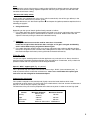
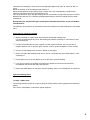
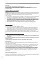
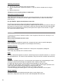
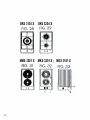
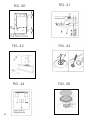
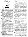
Instructions Booklet built-in cooktops Gebrauchsanweisungen kochmulden, Einbauversion GKS 3134 X MMS 3201 X MGS 3101 X GKS 3204 X MKS 3201 X Important warnings and tips for use ♦ ♦ ♦ ♦ ♦ ♦ ♦ ♦ ♦ ♦ ♦ ♦ IMPORTANT! This manual constitutes an integral part of the appliance. It must be kept intact and within easy reach during the entire life of the cooktop. Please carefully read this manual and all the instructions contained herein before using the appliance. Keep any spare parts supplied with the appliance. Installation must be carried out by a qualified technician and in compliance with current regulations. This appliance is intended solely for domestic use and is designed for the following functions: cooking and reheating food. Any other use is considered as improper. The manufacturer declines all liability resulting from poor installation, tampering, inexpert use and use for purposes other than those specifically stated. Check that the appliance has not been damaged during transport. Keep all packaging materials (plastic bags, polystyrene foam, nylon, etc.) away from children, as they are potentially dangerous. . Dispose of The packaging material is recyclable, and marked with the recycling symbol the appliance responsibly. This appliance must be used by adults only. Make sure children do not touch the controls or play with the appliance. Installation and gas/electrical connections must be carried out by a qualified technician in accordance with the manufacturer's instructions and in full compliance with current laws and safety regulations. Electrical safety can only be guaranteed if the product is connected to a suitable earth connection. It is dangerous to modify or attempt to modify the appliance. In the event of a malfunction, do not attempt to repair the appliance yourself, but contact a qualified technician. After using the cooktop, ensure the indicator on the knob is turned to the "off" position and close the mains gas delivery tap or the gas cylinder tap. Should you decide not to use the appliance any longer, before scrapping it make it unusable in accordance with current environmental health and safety laws, ensuring any parts which might constitute a danger to children are rendered harmless. The appliance data plate, with technical specifications, is positioned at a visible point under the safety cover and is also enclosed with this manual. The data plate below the safety cover must under no circumstances be removed. Illustrations for the use of the appliance are grouped together at the end of this manual. Declaration of Conformity This appliance conforms to the following EC directives: − 90/396/EEC “Gas safety requirements” − 73/23/EEC “Low voltage” − 89/336/EEC “Electromagnetic compatibility” − 93/68/EEC “General Standards” − 89/109/EEC “Materials or objects destined to come into contact with foodstuffs” These instructions are valid only for those countries whose ID initials appear on the data plate found on the instructions handbook and on the appliance. 1 COOKTOP SPECIFICATIONS Warnings: This appliance is designed to be built into a housing unit. ♦ The installation class is type 3 for gas and type Y for electric parts. ♦ Housing units must be designed to withstand temperatures of up to 90°C or over. ♦ For correct installation, refer to the relevant paragraph and reference drawings. ♦ The use of a gas cooking appliance produces heat and humidity in the room in which it is installed. Ensure the kitchen is well ventilated: keep natural ventilation openings open, or install a mechanical ventilation device (extractor hood with exhaust duct). In the case of intensive or prolonged use of the appliance it may be necessary to provide additional ventilation, for example, by opening a window, or more efficient ventilation, for example by increasing the hood speed. This handbook is valid for several types of cooktop. Refer to the data plate on the back in order to identify the model (Mod. Tc) that corresponds to your appliance. These initials, together with the instructions in the following paragraphs and the illustrations at the back of the manual (Fig1-33) will show the particular composition of your appliance. 2 USING THE COOKTOP Gas burners The delivery of gas to the burners is controlled by the knobs shown in fig. 36 that in turn control the taps. The symbols, depending on the various versions, may be printed on the knobs or on the control panel. By moving the indicator to coincide with the printed symbols, the following adjustments can be made: OTap closed, no gas delivery Maximum capacity, maximum gas delivery Minimum capacity, minimum gas delivery Burner ignition - Burners with electric ignition Models with ignition incorporated in the control knobs These models are identified by the symbol ( (Maximum delivery). To light one of the burners, press the knob down and turn it to the maximum delivery position, holding down until the burner lights. Next adjust the flame by turning the knob to obtain the desired intensity. 3 Note: If the particular nature of the local gas supply makes it difficult to ignite the burners with the knob turned to the maximum setting, repeat the operation without a pan in position and with the knob turned to the minimum setting. - Burners with safety valves Some models are equipped with safety valves which automatically shut off the gas delivery in the event the burner should, for any reason, go out. To relight the burner, turn the knob to position O and repeat the ignition procedure explained in the following paragraphs. Using the burners Depending on the type of electric ignition fitted, proceed as follows: ) For models fitted with ignition incorporated in the knobs, turn the gas tap knob to the maximum delivery position, then press and hold down for about 4÷5 seconds. Release the knob and adjust the flame by turning the knob to the desired intensity. ) 'Warning': The ignition device must not be used for more than 15 seconds. If after this length of time the burner does not light, or if it goes out again accidentally, wait 1 minute before trying to ignite the burner again. ) For models fitted with ignition switch, turn the gas tap knob to the maximum delivery position, then press the ignition switch and the knob, holding down for about 4÷5 seconds. Then release the knob and adjust the flame by turning the knob to the desired intensity. Using the grids The panstand grids are designed to make the appliance easy and safe to use. Always check the panstand grids are properly positioned before using the appliance. Furthermore, always check the protective rubber feet are all present and correctly positioned. Special “WOK” support grid (Fig. 35 optional) This is placed on top of the triple crown burner when using a “WOK” (concave bottom pan). In order to prevent serious malfunction of the burner, never use a wok without this special grid and never use the wok grid for flat bottomed pans Choosing the right burner The symbols stamped on the control panel (fig.36) next to the knobs indicate which knob corresponds to which burner. To choose the most suitable burner, take into account the diameter of the pan as well as the pan capacity (see table). The diameter of the pan must be proportionate to the burner power in order to ensure high yield. Pan diameter Burner Auxiliary Rapid Triple crown Fish kettle Minimum diameter Maximum diameter 60 mm (with 140 mm reducer) 200 mm 240 mm 240 mm 260 mm Maximum dimensions: 140X350 mm 4 Electric hotplates Never cook food directly on the electric hotplates; always use suitable pots or containers Switching on the hotplate To switch on the electric hotplate, turn the knob to the desired position. Numbers 1 to 6, depending on whether the cooktop is fitted with a power switch or regulator, indicate the settings in progressing temperature (See Table). When the electric hotplate is in operation an indicator led on the control panel lights up. Using the electric hotplate Once the pan has reached the boil, adjust the power to suit the intensity of heating required, bearing in mind that the hotplate will continue to emit heat for several minutes after being switched off. When using the hotplate, remember: ) Never under any circumstances use the hotplate without a suitable receptacle. Idle operation of the hotplate, especially for prolonged periods of time, can cause fires. ) Take all precautions possible to avoid spilling liquids onto the hotplate when it is hot. ) Use flat bottomed pans only with a diameter such as covers the entire burner surface. Knob position 0 1 2 Type of cooking Off For melting (butter or chocolate) 2 For keeping food warm or reheating small amounts of liquids 3 Reheating larger quantities, whipping creams and sauces 4 Simmering, soups, pasta, risottos, continuation of steaming, cooking steaks and fries in general 4 5 Browning meats, roast potatoes, fried fish and for bringing large quantities of water to the boil 6 Brisk frying, griddling steaks etc. Type of hotplate The cooktop equipped with rapid hotplate. For technical specifications refer to “Cooktop Specifications– Cooking point” Essentially, the rapid hotplate differs from the conventional one because it offers : ) Greater power. ) More rapid reaching of desired temperature. Glass-ceramic cooktop. The glass-ceramic cooktop permits rapid vertical transmission of heat from the heating element below the cooktop to the pots or pans placed on top of it. Heat does not spread horizontally, thus at a distance of just a few centimetres from the cooking zone, the glass remains ” cool” to the touch. The cooking zones are controlled by a power switch with 7 different positions or by a continuous regulator with 10 positions, as shown in figure 37 5 The intensity of heating for each zone can be adjusted progressively from “0” (off) to “6” 0R “11” (max). When the cooktop is on the indicator light remains lit. When the temperature of the cooking zone is above 70°C, the corresponding “residual heat” indicator lamp lights up to warn that the zone is hot. This lamp remains lit even after the cooking zone is switched off, to signal that the zone is still hot. Residual heat persists for a relatively prolonged period of time after the cooking zone has been switched off. During this time, avoid touching the cooking zone and take precautions to ensure children cannot touch it. The indicator lamp switches off automatically once the temperature of the cooking zone falls below 70°C. Safety tips for using the cooktop ) Before switching on, check which knob controls the desired cooking zone. It is best to place the pot or pan on the cooking zone before switching on, and remove it only after switching off. ) Use only flat bottomed pans with a regular surface (exercise caution with cast iron pans). Irregular bottoms can scratch the glass-ceramic surface. Check the bottom is clean and dry ) Do not use the cooktop if the surface is broken or damaged. ) Bear in mind that the cooking zones remain hot for a relatively long time (about 30 min.) after switching off. ) Do not allow heavy or sharp objects to fall on the glass-ceramic cooktop. ) If you find a crack on the cooktop, disconnect the appliance from the mains electricity immediately and contact the After-sales Service. ) Never cook food directly on the glass-ceramic cooktop; always use suitable pots or containers. Types of cooking zones “hi-light” radiant zone The heating element comprises a tape heating coil which reaches working temperature extremely quickly. This zone is controlled by a continuous power regulator. 6 INSTALLATION INSTRUCTIONS Important! These instructions are intended for qualified technicians. The appliance must be installed correctly, in compliance with current laws. Before carrying out any operation on the appliance, it must be disconnected from the electricity supply. Fitting the appliance in the worktop The cooktop may be fitted into any worktop, as long as it is heat resistant (minimum temperature of 90°C). The dimensions of the hole to be made in the worktop and the minimum distances between rear and side walls and those above the appliance are shown in figures 38 and 39. Bear in mind that: ) If the cooktop is installed without an oven below it, a separator panel must be placed between the bottom of the cooktop and the housing below it, at a minimum distance of 10 mm. ) If the cooktop is installed over an oven, place a separator panel at a minimum distance of 15 mm and follow the oven manufacturer's instructions, ensuring nonetheless sufficient aeration as specified in fig. 40. In any event, the electrical connection of the two appliances must be carried out separately, both for electrical purposes and to facilitate removal. It is advisable to use an oven equipped with an internal forced cooling system. Fixing the cooktop To fix the cooktop in the housing, proceed as follows: ) Position the special gasket supplied along the outer perimeter of the worktop, following the diagram shown in fig. 38, so that the ends of the gasket meet exactly without overlapping. ) Position the cooktop into the worktop, taking care to ensure it is placed exactly in the centre. ) Fix the cooktop to the worktop using the special brackets supplied, as shown in fig. 41. Correct installation of the sealing gasket ensures complete protection against infiltration of liquids. Installation area and removal of combustion fumes The appliance must be installed and operated in suitable areas, and in compliance with ) current laws. The installation technician must observe current laws governing ventilation and removal of combustion fumes. The air required for combustion is 2m/h per kW of power (gas) installed. Installation area In the room where the gas appliance is installed, there must be a sufficient natural air supply to allow the gas to burn correctly. The natural flow of air must take place through an opening made on an outside wall of the room 2 and having a working section of at least 100 cm (A). In the case of appliances without safety 2 valves, this opening must have a minimum working section of 200 cm (fig. 42). This opening must be made in such a way that it cannot be obstructed from inside or outside. It should be positioned near floor level, preferably on the side opposite the fume exhaust devices. If it is not possible to make the necessary openings, the air can be supplied from an adjacent, suitably ventilated room, as long as this room is not a bedroom, a dangerous area or a lowpressure area. Removal of combustion fumes Combustion fumes produced by gas appliances must be removed by means of a hood connected directly either to an exhaust duct or to the outside (fig. 42). 7 If a hood cannot be installed, an electric extractor fan must be fitted to the outside wall or the window. This electric extractor fan must have a sufficient capacity to guarantee a change of air of the kitchen of at least 3-5 times its volume. Components shown in fig. 4 A : Opening for air supply C : Hood for exhaust removal of combustion fumes E : Electric extractor fan for removal of combustion fumes Connection to gas supply ) Before installation, make sure the type and pressure of the local gas supply are compatible with the cooktop settings. To do this, check the data on the appliance data plate on the cooktop as well as on this handbook. The gas connection must be carried out by a qualified technician in compliance with local current regulations. If using metal hoses, ensure these do not come into contact with any movable parts and are at no point crushed. Carry out the connection in such a way as does not cause any stress whatsoever on the appliance. The gas supply connector is threaded G½”. For ISO R7 connections, the gasket is not required. For ISO R228 connections, the washer supplied must be fitted. ) After connection operations, check for leaks using a soapy solution. Electrical connection (Fig. 44) Before connecting the appliance to the electricity supply, check that the voltage corresponds to that on the data plate and that the power supply cable is suitable for the appliance load also stated on the data plate. If the appliance is connected directly to the mains, fit an all-pole disconnect switch with minimum contact gap of 3 mm, adequate for the appliance load and complying to regulations. ) Do not use reducers, adapters or switches for connection to the mains, since these could overheat and cause burns. ) Regulations require that the appliance is earthed. The manufacturer declines all liability resulting from failure to observe this regulation. If the power cable must be replaced, use a cable having identical characteristics to the original supplied by the manufacturer, suitable for the load and temperature (type T90°C). This is available from After-sales service. Furthermore, the end of the power cable to be connected to the appliance must have the Yellow-Green earth conductor 20 mm longer than the other conductors. Refer to the table below for the size of the power cable Type of cooktop Only gas burners With electric power up to 1000W With electric power above 1000W Size 3X0.50 mm2 3 X 0.75 mm2 3 X 1.5 mm2 ADJUSTMENT TO DIFFERENT TYPES OF GAS If a different type of gas from the one indicated on the rating plate is used, the injectors must be replaced. If spare injectors are not supplied with the appliance, they are available from the After-sales service. For the choice of replacement injectors, refer to the injectors table. The injectors are identified by their diameter, which is expressed in hundredths of mm, stamped on the body of the injector itself. 8 Replacing the injectors Remove the grids and burner caps from the cooktop Using a socket wrench, replace the injectors “J” (fig. 43) with the suitable ones for the gas used. Replace the burners. The burners do non require primary air adjustment. Adjustment of minimum setting After replacing the injectors, light the burner and remove the knob. Turn the tap to the minimum setting and insert a screwdriver in the rod: tighten to reduce the flame, loosen to increase the flame. (fig. 43) For gas G30/G31, tighten the adjustment screw fully The flame must be small, uniform and regular all around the burner crown. Finally, check that the flame does not go out by rapidly turning the tap from the maximum setting to the minimum. For burners with a safety device, check that the flame slightly licks the thermocouple. Make sure that the adjustment is correct by leaving the burner alight for a few minutes. If it goes out, increase the minimum setting. CLEANING To maintain the cooktop in optimum condition, clean it regularly after each use, allowing it to cool before cleaning. Never remove the knobs from their seats Cast Iron Parts All enamelled parts should be cleaned with a sponge and soapy water or specific detergents. Never use abrasive cleaning products. Dry thoroughly after cleaning. Stainless steel top The stainless steel top should be cleaned with a damp cloth and proprietary detergents commercially available. After rinsing, dry preferably with a chamois leather. Grids Stainless steel panstand grids may take on a bluish tinge on parts around the burners as a result of the high temperatures. This effect can be reduced by using commercially available steel wool pads Burners The burners, comprising two parts, can be removed and cleaned using suitable detergents. After cleaning, dry the burners thoroughly and reposition them carefully in their seats. In models with electric ignition, always check that the electrode “E” (fig. 45) is clean. In models with safety device, clean the probe “T” (fig. 45) in order to allow regular operation of the safety valve. Both the electrode and probe must be cleaned with care. Upon completion of cleaning, replace the burners accurately in their seats. To prevent damaging the electric ignition, avoid using it when the burners are not in place. Electric hotplates The electric hotplates should be cleaned when they are only slightly warm. Clean with a damp cloth, then finish off with a cloth dampened with mineral oil. 9 . MAINTENANCE The appliances do not require any particular maintenance, nonetheless it is advisable to have them checked at least once every two years. If the knobs become difficult to turn, or if there is a smell of gas, shut the gas supply tap and call After-sales service. Faulty taps must be replaced along with their gasket. 10 Cat.: II 2H 3+ IT GB ES PT CH IE Tipo di gas/ gas type/ type de gaz/ tipo de gas/ tipo de gás/ gaz type Pressione del gas/ gas pressure/ pression gaz/ presion gas/ pressão gas Bruciatori/ burners/ bruleurs/ quemodores/ bocas de gás/ branders A SR R TC P/F Portata/power inputs/débit gas/capacidad/va zão /debiet Portata/power inputs/débit gas/capacidad/va zão /debiet Max (kW) 1.00 1.75 3.00 3.30 2.90 Min (kW) 0.30 0.44 0.75 1.50 1.50 Tipo di gas/ gas type/ type de gaz/ tipo de gas/ tipo de gás/ gaz type Pressione del gas/ gas pressure/ pression gaz/ presion gas/ pressão gas Bruciatori/ burners/ bruleurs/ quemodores/ bocas de gás/ branders A SR R TC P/F Portata/power inputs/débit gas/capacidad/va zão /debiet Portata/power inputs/débit gas/capacidad/va zão /debiet Max (kW) 1.00 1.75 3.00 3.30 2.90 Min (kW) 0.30 0.44 0.75 1.50 1.50 G20 20 mbar Ø Iniettore/injectors/ injecteur/inyector/ injector/sproeier 0.72 0.97 1.15 1.24 1.20 G30/G31 28-30/37 mbar Ø Iniettore/injectors/ injecteur/inyector/ injector/sproeier 0.50 0.65 0.85 0.91 0.85 Only for Australian and New Zealand Tipo di gas/ gas type/ type de gaz/ tipo de gas/ tipo de gás/ gaz type Pressione del gas/ gas pressure/ pression gaz/ presion gas/ pressão gas Bruciatori/ burners/ bruleurs/ quemodores/ bocas de gás/ branders A SR R TC P/F Portata/power inputs/débit gas/capacidad/va zão /debiet Portata/power inputs/débit gas/capacidad/va zão /debiet Max (kW) 1.00 1.75 3.00 3.30 2.90 Min (kW) 0.30 0.44 0.75 1.50 1.50 Tipo di gas/ gas type/ type de gaz/ tipo de gas/ tipo de gás/ gaz type Pressione del gas/ gas pressure/ pression gaz/ presion gas/ pressão gas Bruciatori/ burners/ bruleurs/ quemodores/ bocas de gás/ branders A SR R TC P/F 11 Portata/power inputs/débit gas/capacidad/va zão /debiet Portata/power inputs/débit gas/capacidad/va zão /debiet Max (kW) 1.00 1.75 3.00 3.30 2.90 Min (kW) 0.30 0.44 0.75 1.50 1.50 G20 1.0 kPa Ø Iniettore/injectors/ injecteur/inyector/ injector/sproeier 0.90 1.18 1.55 1.60 1.55 G30/G31 2.75 kPa Ø Iniettore/injectors/ injecteur/inyector/ injector/sproeier 0.53 0.69 0.90 0.97 0.90 GKS 3134 X GKS 3204 X MMS 3201 X MKS 3201 X MGS 3101 X 12 FIG.35 FIG. 37 FIG. 36 0 0 6 1 FIG.34 2 FIG. 38 4 2 10 5 3 1 9 3 4 8 7 6 5 FIG. 39 13 FIG. 40 FIG. 41 C:Min. 3 mm D;E; Min.10 mm 14 FIG. 42 FIG. 43 FIG. 44 FIG. 45 H01A262