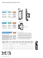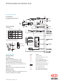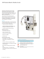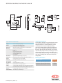
1
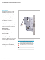
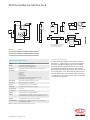
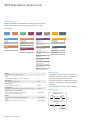
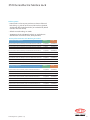
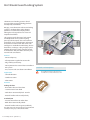
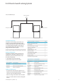
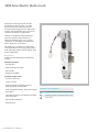
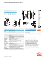
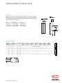
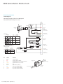
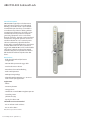
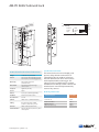
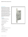
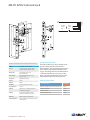
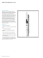
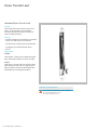
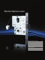
Electric Mortice Locks
3570 Series Electric Mortice Lock
30
3579 Series Electric Mortice Lock
36
3579HS Series Electric Mortice Lock
38
Hi-O Room Guard Locking System
40
3580 Series Electric Mortice Lock
42
EL402 Solenoid Lock
48
EL502 Solenoid Lock
50
EL648 Motor lock
52
Power Transfer Lead Cover
54
3570 Series Electric Mortice Lock
General Information
Designed and manufactured in Australia,
the 3570 series electric mortice is a high
performance lock of superior quality. It is
constructed from high grade zinc alloy, with a
stainless steel latch bolt and face plate and is
suited for all commercial applications.
The lock can be operated by push buttons,
intercom systems and key switches; or
integrated with electronic access control
systems for use with higher security devices
such as keypads or card readers.
Key Features
Designed with flexibility in mind, the one lock
can cover all functions and is easily configured
on site for the required application.
Available in non monitored and monitored
versions.
Monitoring features:
• Dead latched and Locked
• Door position/Reed switch
• Dual key override monitoring
• Request to exit/REX
• LED indication
Field Changeable settings:
• Fail safe/fail secure configuration.
•Multi-voltage - will work on 12-24 Vdc systems.
• Handing - left hand and right hand doors
• Selection of free lever or locked lever on both
sides of the door
• Key override monitoring either side of the door
• Monitoring contacts – normally closed,
normally open (for key override and request
to exit only)
Standards and Compliance
S3
(Security) Australian Lock Standard (AS4145.2.1993)
(when used with equivalent security level keying system)
D3
(Durability) Australian Lock Standard (AS4145.2.1993)
4
Hour
Successfully fire rated up to 4hrs on fire door assemblies
in accordance with AS1905.1. 2005
(Part 1: Fire resistant door sets)
C-Tick Certified
3570 Series: SCEC endorsed for intruder resistant areas
3579 Series: SCEC endorsed for secure areas
30 assaabloy.com.au (Version 1.1)
3570 Series Electric Mortice Lock
A
37
26
A
37
28.5
124
26
64 14
14
175
24
57
68
68
28.5
64
124
175
4
57
39
18
30
70
15
25
B
54
15
19
Dimension
Backset
A
18
60
89
127
B
100
129
167
1.5
28.5
18
1.5
Note: width of case increases
from 19mm46
to 23 mm for
32
3579 series
SCEC lock
28.5
15
54
19
70
4
Reed Magnet
25
B
15
30
39
32
46
38
38
3570 Technical Information
Voltage
12Vdc - 24Vdc Operating Voltage
Current
500mA (max) 80mA holding @ 12Vdc
275mA (max) 50mA holding @ 24Vdc
LED Current
When LED’s are fitted, add 15mA (max) to total current draw
Monitoring
Dual Key override
Deadlatched
Locked
Door closed
Request to exit
Microswitches: 500mA (max) @ 30Vdc each circuit.
Reedswitch: 100mA (max) @ 30Vdc
Environment
Operational temperature range -20c to + 60c
Case/ Cover
High purity Zinc alloy construction
Backset
60mm standard, 89 & 127 mm available
Latch bolts
Reversible with Stainless Steel construction.
Door Clearance
3 – 6.5 mm
Door thickness
Standard applications 32 to 50mm.
Cylinder
Standard Lockwood oval shaped cylinders.
Cabling
1.6 metre length of cable with 12 pin socket supplied with each lock.
Recommended cable: 18AWG (0.82mm²) cable runs up to 30m.
Furniture
Compatible with Lockwood series door furniture.
Standard Finishes
Satin Chrome(SC) standard. Bright Chrome (CP) and Polished
Brass(PB) finishes available
Specification Statement
The lock should be capable of operation on voltages
between 12 – 24Vdc and have a current consumption
not more than 80mA (holding) @12Vdc and 50mA
(holding) @24Vdc. Monitored locks must be capable
of monitoring the following functions: Key override,
door position / reed switch, selectable hub / Request to
exit, & locking bar status. All monitoring outputs must
have the ability to be wired independently. All settings
– including: fail safe / fail secure, handing, hub selection
must be field configurable.
Note: For detailed electrical specifications, turn to page 5
assaabloy.com.au (Version 1.1)
31
3570 Series Electric Mortice Lock
Ordering Procedure
Sample Part Number 3572ELAM2RSC is made up of several sections.
Choose your product by selecting an option from each section.
For example:
Backset
3
Fixing
Lock
Functions
5
Electric
Lock
72
Backset
Safety
Function
EL
A
60 mm
3
Primary lock
70
89 mm
4
Vestibule lock
72
127 mm
5
Combination lock
74
Secure Area Rated Lock
79
Standard
5
Electric Lock
Electric Lock
EL
Finish
R
M2
SC
Right Handing
Safety Function
Lock Functions
Fixing
Handing
Sub
Function
Fail Safe
(Power to lock)
A
Fail Secure
(Power to unlock)
E
Right Handing
R
Left Handing
L
Finish
Sub Function
Non-monitored lock
(0 Cylinders) N0
Non-monitored lock
(1 Cylinders) N1
Non-monitored lock
(2 Cylinders) N2
Satin Chrome
SC
Chrome Plate
CP
Polished Brass
PB
Fully monitored lock including
KOM (0 Cylinders)
M0
Fully monitored lock including
KOM (1 Cylinder)
M1
Fully monitored lock including
KOM (2 cylinders)
M2
KOM(Key override monitored)
Ordering Notes
Backset
Nominate backset as required, eg 60mm
3
Fixing
Select the desired fixing method, eg Standard Fixing 35
35
Lock Function
Select function, eg Vestibule Lock
3572
Electrical Variant
Indicate that this is an Electric Lock
3582EL
Safety Function
Select whether lock should be Fail Secure or Fail Safe, eg Fail Safe
3572ELA
Monitoring and Key Override Options
Select monitoring and cylinders to be supplied,
eg Monitored Lock with two cylinders
Handing
Determine left or right handing, eg Right Handed
F inish
Specify appropriate finish, eg Satin Chrome
• 3570 Primary Locks can be set to achieve all
lock functions post purchase, and should be
the preferred option when ordering.
• Customised locks are available upon request
and incur an additional surcharge and 10 day
lead time.
• See over page for Primary Lock part numbers.
Handing Chart
3572ELAM2
3572ELAM2R
DOOR OPENING IN
RIGHT
HAND
INSIDE
LEFT
HAND
OUTSIDE
3572ELAM2RSC
DOOR OPENING OUT
INSIDE
RIGHT
HAND
32 assaabloy.com.au (Version 1.1)
OUTSIDE
LEFT
HAND
3570 Series Electric Mortice Lock
Ordering Notes
• Primary locks can be set post purchase to achieve all desired
lock settings e.g. fail safe or fail secure, left hand or right hand,
combination lock (locked both sides) or vestibule lock (locked
outside & free lever inside)
• All locks are Multi-voltage 12-24Vdc
• 3570 Primary locks (std 60mm backset) are stocked items.
All other items are made to order, 10 day lead time.
Primary Electric Mortice Lock Ordering Procedure
Description - Non-Monitored
Cylinders
Part No
Electric Mortice Lock 3570 Primary Lock 60 mm Backset Non Monitored
No Cylinder
3570ELN0SC
Electric Mortice Lock 3570 Primary Lock 60 mm Backset Non Monitored
1 Cylinder
3570ELN1SC
Electric Mortice Lock 3570 Primary Lock 60 mm Backset Non Monitored
2 Cylinder
3570ELN2SC
Electric Mortice Lock 4570 Primary Lock 89mm Backset Non Monitored
No Cylinder
4570ELN0SC
Electric Mortice Lock 4570 Primary Lock 89 mm Backset Non Monitored
1 Cylinder
4570ELN1SC
Electric Mortice Lock 4570 Primary Lock 89 mm Backset Non Monitored
2 Cylinder
4570ELN2SC
Electric Mortice Lock 5570 Primary Lock 127 mm Backset Non Monitored
No Cylinder
5570ELN0SC
Electric Mortice Lock 5570 Primary Lock 127 mm Backset Non Monitored
1 Cylinder
5570ELN1SC
Electric Mortice Lock 5570 Primary Lock 127 mm Backset Non Monitored
2 Cylinder
5570ELN2SC
Description - Monitored
(hub, deadlatch, solenoid, door position, key override monitoring all as standard)
Cylinders
Part No
Electric Mortice Lock 3570 Primary Lock 60 mm Backset Monitored
No Cylinder
3570ELM0SC
Electric Mortice Lock 3570 Primary Lock 60 mm Backset Monitored
1 Cylinder
3570ELM1SC
Electric Mortice Lock 3570 Primary Lock 60 mm Backset Monitored
2 Cylinder
3570ELM2SC
Electric Mortice Lock 4570 Primary Lock 89 mm Backset Monitored
No Cylinder
4570ELM0SC
Electric Mortice Lock 4570 Primary Lock 89 mm Backset Monitored
1 Cylinder
4570ELM1SC
Electric Mortice Lock 4570 Primary Lock 89 mm Backset Monitored
2 Cylinder
4570ELM2SC
Electric Mortice Lock 5570 Primary Lock 127 mm Backset Monitored
No Cylinder
5570ELM0SC
Electric Mortice Lock 5570 Primary Lock 127 mm Backset Monitored
1 Cylinder
5570ELM1SC
Electric Mortice Lock 5570 Primary Lock 127 mm Backset Monitored
2 Cylinder
5570ELM2SC
assaabloy.com.au (Version 1.1)
33
3570 Series Electric Mortice Lock
12.7
14.1
4
Accessories - Rebate Kits
“A”
Finish
1.5
Part Number
Chrome Plate
32
46
3P72-RK32CP
3P72-RK46CP
Polished Brass
32
46
3P72-RK32PB
3P72-RK46PB
Satin Stainless Steel
32
46
3P72-RK32SS
3P72-RK46SS
177
184
51
75
26.5
13.5
29
Accessories - Long Lipped Strikes
“A”
Finish
1.5
Part Number
46
Bright Chrome
43.5
47.5
3570-5353CP
3570-5653CP
Polished Brass
43.5
47.5
3570-5353PB
3570-5653PB
Satin Stainless Steel
43.5
47.5
3570-5253SSS
3570-5453SSS
28.5
70
54
38
Long Lipped Strike
A
Accessories Ordering Information
Product Description
Extended Cylinders
Part Number
LED assembly to suit 3570/3580
(suits furniture for monitored locks) Extended cylinders should be considered when a
door thickness is 50mm or greater or when the lock
is mounted off centre in the door. Use Lockwood’s
new Modular Cylinder Extensions to produce an
extended cylinder. Virtually any length cylinder can
be made by stacking as many or as few extension
pieces as required together and screwing them into
the back of a special extended cylinder base.
SP572-3129
7.5m extended 12 wire cable
SP3570-1055
9/12 wire adaptor to suit 3570 series electric lock
SP3570-5861
323mm Power Transfer Cable
LC8810
543mm Power Transfer Cable
LC8811
Extended Cylinders
Overall
cylinder length
required
Cylinder
projection
(A)
Door thickness
Extended
base
cylinder
7mm
extension
kit
10mm
extension
kit
34
36
35
50
41
43
50
63
51
53
63
83
1
1
1
61
63
83
103
1
1
2
72
74
103
123
1
2
82
84
123
143
1
94
143
163
1
A
32mm
assembly
screw
42mm
assembly
screw
65mm
assembly
screw
A
Standard Mortice Cylinder
1
92
34 assaabloy.com.au (Version 1.1)
24mm
extension
kit
1
2
2
2
1
1
2
2
2
2
2
A
3570 Series Electric Mortice Lock
Electrical Specifications
12 Pin
Connector
Circuit Diagram
Note: Diagram depicts fail safe RH opened
door, with handle and key in rest state.
DIL Switch Settings
Hub Monitor
Lock
Side
Switch Number
1
2 3
4
Normal
Function
ON
OF F
A
N/C
ON
OF F
A
N/O
ON
OF F
B
N/C
ON
OF F
B
N/O
Deadlatched and locked
centre tap (White)
Key Override Monitor Selection
SIDE B
Key
Override
Monitor
Selection
Key Override
N/O Monitor Selection
N/C
K.O.M
SWITCH
SELECTION
Set the 2 way switch
to desired setting
Hub
Monitor
Selecion
Solenoid Activation
Colour
Function
Operating Voltage:
12 - 24Vdc
Black
Solenoid (0Vdc)
Red
Solenoid Positive (12Vdc - 30Vdc)
Operating Current:
500mA (max) 80mA holding @ 12Vdc
275mA (max) 50mA holding @ 24Vdc
Green
LED (12Vdc - 30Vdc)
Yellow
Door closed Reedswitch (NC)
Pink
Door closed Reedswitch (common)
Light Blue
Deadlatched and Locked (NC)
Grey
Deadlatched and Locked (common)
White
Deadlatched and Locked centre tap
LED Current
Brown
Hub monitor (NO or NC)
Where LEDs are fitted, add 20mA (max) to total
operating current.
Blue
Hub monitor (common)
Orange
Key override monitor (NO or NC)
Violet
Key override monitor (common)
For confirmation of the above mentioned
operating current, please see installation manual.
Monitoring Circuits
Microswitches: 500mA (max) @ 30Vdc each circuit
Reedswitch: 100mA (max) @ 30Vdc
assaabloy.com.au (Version 1.1)
35
3579 Series Electric Mortice Lock
Designed and manufactured in Australia,
the 3579 series electric mortice is a high
performance lock of superior quality. It is
constructed from high grade zinc alloy secured
between stainless plates making suitable for
high security applications.
The 3579 lock can be operated by push
buttons, intercom systems and key switches;
or integrated with electronic access control
systems for use with higher security devices
such as keypads or card readers.
Features
Designed with flexibility in mind, the one lock
can cover all functions and is easily configured
on site for the required application.
• Stainless Steel Latch and Faceplate
•S
tainless steel plates that encapsulate the
body against attempted vandalism
• Available in Monitored versions only
Monitoring Features
• Dead latched and Locked
• Door position/Reed switch
• Dual key override monitoring
• Request to exit/REX
• LED indication
Field Changeable Settings
• Fail safe/fail secure configuration.
•M
ulti-voltage - will work on 12-24 Vdc
systems.
• Handing - left hand and right hand doors
•S
election of free lever or locked lever on both
sides of the door
Standards and Compliance
SL8
Australian Lock Standard (AS4145.2.1993)
(when used with equivalent security level keying system)
D8
(Durability) Australian Lock Standard (AS4145.2.1993)
4
Hour
•K
ey override monitoring either side of the
door
•M
onitoring contacts – normally closed,
normally open (for key override and request to
exit only)
36 assaabloy.com.au (Version 1.1)
Successfully fire rated up to 4hrs on fire door assemblies in
accordance with AS1905.1.2005
(Part 1: Fire resistant door sets)
C-Tick Certified
SCEC endorsed for secure areas
3579 Series Electric Mortice Lock
A
37
26
A
37
28.5
124
64 14
26
14
175
24
57
68
68
28.5
64
124
175
4
57
39
18
30
70
15
25
B
54
23
70
4
Reed Magnet
25
B
15
30
39
1.5
28.5
54
18
1.5
32
46
15
28.5
15
19
18
32
46
38
38
3579 Technical Information
Specification Statement
The lock body should be encapsulated with stainless
steel The lock should be capable of operation on
voltages between 12 – 24Vdc and have a current
consumption not more than 80mA (holding)
@12Vdc and 50mA (holding) @24Vdc. Monitored
locks must be capable of monitoring the following
functions: Key override, door position / reed switch,
selectable hub / Request to exit, & locking bar status.
All monitoring outputs must have the ability to be
wired independently. All settings – including: fail safe
/ fail secure, handing, hub selection must be field
configurable.
Voltage
12Vdc - 24Vdc Operating Voltage
Current
500mA (max) 80mA holding @ 12Vdc
275mA (max) 50mA holding @ 24Vdc
LED Current
When LED’s are fitted, add 15mA (max) to total current draw
Monitoring
Dual Key override Deadlatched
Locked
Door closed
Request to exit Microswitches:
500mA (max) @ 30Vdc each
circuit. Reedswitch: 100mA
(max) @ 30Vdc
Environment
Operational temperature range -20c to + 60c
Case/ Cover
High purity Zinc alloy construction with Stainless Steel plates
Backset
60mm standard, 89 & 127 mm available
Latch bolts
Reversible with Stainless Steel construction
Door Clearance
3 – 6.5 mm
Door thickness
Electric Mortice 3579 Primary Lock 60 mm Mon
3579ELM0SC
Standard applications 32 to 50mm
Electric Mortice 3570 Primary Lock 89 mm Mon
4579ELM0SC
Cylinder
Standard Lockwood oval shaped cylinders
Electric Mortice 3570 Primary Lock 127 mm Mon
5579ELM0SC
Cabling
1.6 metre length of cable with 12 pin socket supplied with each lock.
Recommended cable: 18AWG (0.82mm²) cable runs up to 30m
Furniture
Compatible with Lockwood series door furniture
Standard Finishes
Satin Chrome(SC) standard. Bright
assaabloy.com.au (Version 1.1)
Ordering Information
Product Description
Part Number
37
3579HS Series Electric Mortice Lock
Designed and manufactured in Australia, the
3579HS series electric mortice is designed
for unique applications where fail secure
functionality is required externally with fail
safe functionality on the inside. To achieve this
function the lock must be used in conjunction
with an electric strike.
The 3579HS is constructed from the same
material as the 3579 counterpart.
Features
Designed with flexibility in mind, the one lock
can cover all functions and is easily configured
on site for the required application.
• Stainless Steel Latch and Faceplate
•S
tainless steel plates that encapsulate the
body against attempted vandalism
• Available in Monitored versions only
Monitoring Features
• Dead latched and Locked
• Door position/Reed switch
• Dual key override monitoring
• Request to exit/REX
• LED indication
Field Changeable Settings
• F ail safe/fail secure configuration.
•M
ulti-voltage - will work on 12-24 Vdc
systems.
• Handing - left hand and right hand doors
•S
election of free lever or locked lever on both
sides of the door
•K
ey override monitoring either side of the
door
•M
onitoring contacts – normally closed,
normally closed
Note: this lock is designed to operate in conjunction with an
electric strike. The lock will never unlock electrically from the
external side.
38 assaabloy.com.au (Version 1.1)
Standards and Compliance
SL8
Australian Lock Standard (AS4145.2.1993)
(when used with equivalent security level keying system)
D8
(Durability) Australian Lock Standard (AS4145.2.1993)
4
Hour
Successfully fire rated up to 4hrs on fire door assemblies in
accordance with AS1905.1.2005
(Part 1: Fire resistant door sets)
C-Tick Certified
SCEC endorsed for secure areas
3579HS Series Electric Mortice Lock
A
37
26
A
37
28.5
124
26
64 14
14
175
24
57
68
68
28.5
64
124
175
4
57
39
18
30
70
15
25
B
54
23
70
4
Reed Magnet
25
B
15
30
39
1.5
28.5
54
18
1.5
32
46
15
28.5
15
19
18
32
38
46
38
Lock Functions
Specification Statement
The 3579HS series lock is designed to provide
internal emergency egress on doors whereby
the door remains secure on the outside in the
event of a fire alarm or break glass event.
The lock body should be encapsulated with stainless
steel The lock should be capable of operation on
voltages between 12 – 24Vdc and have a current
consumption not more than 80mA (holding)
@12Vdc and 50mA (holding) @24Vdc. Monitored
locks must be capable of monitoring the following
functions: Key override, door position / reed switch,
selectable hub / Request to exit, & locking bar status.
All monitoring outputs must have the ability to be
wired independently. All settings – including: fail safe
/ fail secure, handing, hub selection must be field
configurable. The lock must be capable of operating in
fail safe mode internally and fail secure mode externally
when used in conjunction with an electric strike.
A typical door set up would include the
following hardware:
• Proximity readers on both sides of the door to
gain access either way
• 3579HS Electric Mortice Lock set to fail safe
inside. Note the lock remains in the locked
state (externally)100% of the time if power is
applied or not.
• Electric strike set to fail secure
• Break glass or Fire Panel connected to the
mortice lock only
To enter or exit the door the user would
swipe a proximity card to the reader. Upon
authorisation from the EAC panel the electric
strike would unlock, allowing the user to open
the door. The electric mortice lock does not
change state.
Ordering Information
Product Description
Part Number
High Security Elec Mortice 3579HS
Primary Lock 60 mm
3579HSELM0SC
High Security Elec Mortice 3579HS
Primary Lock 89 mm
4579HSELM0SC
High Security Elec Mortice 3579HS
Primary Lock 127 mm
5579HSELM0SC
In the event of an emergency (fire alarm or
break glass activation), power is cut to the
electric mortice lock & places it in a fail safe
mode on the internal side only. The mortice lock
remains in a fail secure state on the external
side.
NOTE: The 3579HS Series lock can never be electrically
unlocked from the outside. A secondary locking device (electric
strike) must be used in conjunction with this lock.
assaabloy.com.au (Version 1.1)
39
Hi-O Room Guard Locking System
The Room Guard Locking System is based
on state of the art Hi-O technology platform
developed by ASSA ABLOY.
Bringing a new dimension to electronic locking
systems as we know them today, the Hi-O
platform has enabled this unique product
offering that is designed for ease of use and
simplified installation.
The system provides electronic lock control
of multiple doors for any room requiring
privacy by the occupants. The most common
applications are shared bathrooms in hospitals
and conference rooms with dual entries. The
intelligence is embedded in the locking devices
themselves, resulting in a plug and play system
without the need for a door controller to lock
and unlock the door; therefore extremely easy
to install and cost effective.
Features
• One touch privacy
• All components supplied in one neat kit
• Plug and Play connectivity
• No requirement for external door controller or
EAC system
Standards and Compliance
• Fast, accurate and cost effective installation
Applications
• Shared bathrooms
• Conference rooms
• Laboratories
Function
Locking the door
• Enter either door and close door
• Activate internal turn knob
• Both doors automatically lock - outside
• External handles indicate red (locked)
To unlock/exit
• Activate internal lever on either door
• Both doors automatically unlock
• External handles indicate green (unlocked)
Note: In the event of an emergency, the doors may be unlocked
externally via emergency override switches if fitted.
40 assaabloy.com.au (Version 1.1)
4
Hour
Successfully fire rated up to 4hrs on fire door
assemblies in accordance with AS1905.1.2007
Hi-O Room Guard Locking System
Two Door Installation Layout
24V power supply
Hi-O Termination
Emergency override
Emergency override
Installation Overview
The Room Guard Locking System does not
require an external door controller to lock
or unlock the door. The electric mortice locks
are simply plugged together, connected to
the emergency override switches and then
plugged into the power supply.
Note: The use of emergency override switches may not be required.
In that case, the power supply is connected directly to mortice locks.
Ordering Information
The Room Guard Kit contains all necessary
components and power supply to install a
two door system. The door furniture must
be ordered separately.
1. Order Room Guard two door kit
2. Order door furniture for two doors
Room Guard Kit - Contents
Qty
Hi-O Room Guard Mortice Lock
2
Power Transfer
2
Room Guard Turn Knob Assembly
2
24Vdc Power supply unit
1
4 Way Adaptor
1
Override Switch Wire – 15M
2
8M Extension Cable
2
Terminal Strip Adaptor (PAIR)
1
Hi-O Termination Socket
1
Emergency Switch
2
Faceplate for Emergency Switch
2
Spare Part no Description
3570ELHRG0SC
Hi-O Room Guard Mortice Lock
EA280
Power Transfer
Room Guard Kit – 2 doors
RG3SC
Room Guard Turn Knob Assembly
1822/70SC
Exterior door furniture with LED
HPS-24VDC
24Vdc Power supply unit
1920/70SC
Interior door furniture
HLM-004
4 Way Adaptor
HLM-018
Override Switch Wire – 15M
Additional Information
HLM-008
8M Extension Cable
• For alternative door furniture options and
finishes, refer to Lockwood Product Catalogue
Section 3.70 – Plate Door Furniture
HLM-011
Terminal Strip Adaptor (PAIR)
HLM-012
Hi-O Termination Socket
HPM-SW1
Emergency Switch
• Locks are designed to work in fail safe mode
HPM-FP1
Faceplate for Emergency Switch
Part Number
Description
3570HRGKIT
• Locks are non handed and can be configured
on site
assaabloy.com.au (Version 1.1)
41
3580 Series Electric Mortice Lock
Designed and manufactured in Australia,
the 3580 series electric mortice is a high
performance lock of superior quality. It is
constructed from high grade zinc alloy, with a
stainless steel latch bolt and face plate and is
suited for all commercial applications.
The lock can be operated by push buttons,
intercom systems and key switches; or
integrated with electronic access control
systems for use with higher security devices
such as keypads or card readers.
The 3580 series is available in a wide variety
of configurations to suit varying requirements
and is especially suited to narrow style or short
backset applications.
Key Features
Available in non monitored and monitored
versions.
Monitoring features:
• Dead latched
• Door position/reed switch
• Key override
• Request to exit/REX
Available configurations:
• Fail safe or fail secure
• 12Vdc or 24Vdc
• Field changeable monitoring contacts –
normally closed, normally open
• Field changeable handing - Left hand and right
hand doors
• Selection of free lever or locked lever on both
sides of the door
• Key override monitoring
• LED indication
42 assaabloy.com.au (Version 1.1)
Standards and Compliance
S2
(Security) Australian Lock Standard (AS4145.2.1993)
D3
(Durability) Australian Lock Standard (AS4145.2.1993)
C-Tick Certified
3580 Series Electric Mortice Lock
Dimension
Backset
X
23
Y
25
3
15
30
39
43.6
Y
X
X
25.4
36.4
36.5
Y
Limiting Dimensions
15
32
38
15
15
51.7
90
18
212.5
155.5
28
18
79
260
1.5
15
46
15
20
1.5
24
260
1.5
46
32
1.5
24
32
Y
70
54
38
X
24
100 54
86
39
70
54
38
100 54
39
86
15
18
28.5
1.5
27
15
t
28.5 Reed Magne
25
18
27
Available in 12Vdc or 24Vdc
Current
12Vdc ± 5% 250mA (max)
24Vdc ± 5% 125mA (max)
1.5
Product Description
46
24
Anti-Clockwise Rebate Kit Replace ## with finish code (SC, CP, PB)
32
LED Current
When LED’s are fitted, add 15mA (max) to total current draw
Monitoring
Key override
LED Assembly to suit 3570/3580
70
54
Request to exit
Hub/Deadlatch/Key override monitor: max ratings 500mA@30Vdc
Door Status Monitor: max ratings 3W, 250mA (max) @ 12Vdc,
28.5
125mA (max) @24Vdc
Environment
Operational temperature range -20°c to + 60°c
Case/ Cover
High purity zinc alloy construction
Backset
23mm standard. 25.4, 30 & 38 mm extended available
Latch bolts
15mm Stainless Steel construction
Door Clearance
3 – 6.5 mm
Door thickness
Standard applications 32 to 50mm
Extension kits available
Cylinder
Standard Lockwood oval shaped cylinders
Cabling
3.6 metre length of cable with 9 pin socket supplied with each lock.
Recommended cabling: 18AWG (0.82mm²) cable runs up to 30m
Furniture
Compatible with Lockwood series door furniture
Standard Finishes
Satin Chrome(SC) standard. Bright Chrome (CP) and Polished
Brass(PB) finishes available
38
100 54
86
7.5m extended 9 wire cable 39
260
Part Number
15
lockwise Rebate Kit
C
Replace ## with finish code (SC, CP, PB)
Deadlatched and door closed
25
Accessories Ordering Information
3580 Series Technical Information
Voltage
1.5
1.5
3580-2902AC##
35802902CW##
SP572-3129
SP3580-1052
Specification Statement
25
1.5
The lock should27be capable of operation
on voltages of 12 or 24Vdc and have a
current consumption not more than
250mA (max) @12Vdc and 125mA (max)
@24Vdc. Monitored locks must be capable
of monitoring the following functions:
Key override, door position/reed switch
& independent hub/ Request to exit. All
monitoring outputs must have the ability to
be wired independently. The lock must be
capable of operating fail safe or fail secure,
left or right hand, and have field configurable
hub selection.
Note: For detailed electrical specifications, turn to page 48.
assaabloy.com.au (Version 1.1)
43
3580 Series Electric Mortice Lock
Ordering Procedure
Sample Part Number 3582ELAM2RSC62 is made up of several sections.
Choose your product by selecting an option from each section.
For example:
Backset
3
Door
Material
Lock
Function
58
2
Backset
New
Product
Safety
Function
EL
A
Lock Function
3
Vestibule lock
2
25.4 mm
4
Combination Lock
4
30 mm
5
38 mm
6
Metal
58
Timber
59
Handing
M2
R
Safety Function
23 mm
Door Material
Sub
Function
Options
SC
62
Handing
Fail Safe
(Power to lock)
A
E
New Product
Fail Secure
(Power to unlock)
EL
Sub Function
Right Handing
R
Left Handing
L
Finish
Bright Chrome CP
Polished Brass
PB
SC
Non-monitored lock
(0 Cylinders)
N0
Satin Chrome
Non-monitored lock
(1 Cylinder)
N1
Options
Non-monitored lock
(2 Cylinders)
N2
Monitored Lock
(0 Cylinders)
M0
Monitored Lock
(1 Cylinder)
M1
Monitored Lock
(2 Cylinders)
M2
24 volt model
Monitored Lock including
M4
KOM (0 Cylinder)
Monitored Lock including
KOM (1 Cylinder) M5
KOM(Key override monitoring)
Backset
Nominate backset as required, eg 23mm
3
Door Material
Nominate door material, eg Metal
358
Lock Function
Select function, eg Vestibule Lock
3582
Electrical Variant
Indicate that this is an Electric Lock
3582EL
Safety Function
Select whether lock should be Fail Secure or Fail Safe, eg Fail Safe
3582ELA
Monitoring and Key Override Options
Select monitoring and cylinders to be supplied,eg Monitored Lock with 2 cylinders
3582ELAM2
Handing
Determine left or right handing, eg Right Handed
3582ELAM2R
F inish
Specify appropriate finish, eg Satin Chrome
3582ELAM2RSC
Options
Specify 24Vdc opion when required
3582ELAM2RSC62
44 assaabloy.com.au (Version 1.1)
Finish
62
3580 Series Electric Mortice Lock
Accessories
Rebate kits to suit 13 mm rebated timber doors with a minimum backset
of 30 mm includes an adaptor to mount the lock and a special strike plate.
Handing of the rebate kits is determined by the opening movement of the
door on which the lock is fitted.
14
4
12.7
29
1.5
26.5
Finish
Anti-clockwise
Clockwise
Satin Chrome
3580-2902ACWSC
3580-2902CWSC
Bright Chrome
3580-2902ACWCP
3580-2902CWCP
Polished Brass
3580-2902ACWPB
3580-2902CWPB
177
51
184
75
A
Extended Cylinders
Overall
cylinder length
required
Cylinder
projection
(A)
Door thickness
Extended
base
cylinder
7mm
extension
kit
10mm
extension
kit
34
36
35
50
41
43
50
63
1
1
51
53
63
83
1
1
1
2
24mm
extension
kit
32mm
assembly
screw
42mm
assembly
screw
65mm
assembly
screw
A
Standard Mortice Cylinder
61
63
83
103
1
1
72
74
103
123
1
2
82
84
123
143
1
92
94
143
163
1
2
1
2
2
1
2
2
2
2
2
A
A
A
assaabloy.com.au (Version 1.1)
45
3580 Series Electric Mortice Lock
Electrical Specifications
Circuit Diagram
Note: Diagram depicts fail safe 12V RH opened
door, with handle and key in rest state.
9 Pin
Connector
1
Red
Solenoid
2
EXTERNAL
LED
Resistor
C
Lock
Side
4
Normal
Function
ON
OFF
A
N/C
ON
OFF
A
N/O
ON
OFF
B
N/C
ON
OFF
B
N/O
(1)
(2)
NO
C
LHS
Set the 2 WAY DIL SWITCH to desired
setting, refer to table.
Normal
Function
ON
OFF
N/O
ON
OFF
N/ C
C
NO
NO
C
(1)
NC
RHS
NC
(2)
DIL
SWITCH
PinColour
Function
1
Black
Common (0Vdc)
2
Red
Solenoid (12Vdc or 24Vdc)
3
Grey
Deadlatch and door closed status (common)
4
Yellow
Deadlatch and door closed status
5
GreenLED
6
Brown
Hub monitor (common)
7
Blue
Hub monitor (RH/LH, NO/NC)
8
Orange
Key override monitor (NO/NC)
9
Violet
Key override monitor (common)
46 assaabloy.com.au (Version 1.1)
4
5
6
Common
Deadlatch and
door closed status
Deadlatch and
door closed status
LED
Hub monitor
common
(3)
NC
Key Override Monitor Selection
Solenoid
12V dc
NO
NC
Hub Monitor
Switch No.
1 2
3
Reedswitch
Green
Switch No.
1
2 3
Common
Protection
Diode
(4)
7
Hub monitor
( LH/RH, NO/NC )
8
Key override
monitor ( NO/NC )
9
Key override
monitor common
DIL
SWITCH
Plug Housing
From electrical lock
To power supply
Receptacle
Housing
Electric Mortice Locks
assaabloy.com.au (Version 1.1)
47
ABLOY EL402 Solenoid Lock
General Description
ABLOY EL402 is typically used in the interior
doors of business premises and educational
buildings. The locks include a special double
action bolt for quick and easy use and offer a
cost-effective way of electric locking without
compromising performance. The locks can be
controlled by a variety of electrical impulse
generating equipment such as card readers,
keypads and timers. The locks can be connected
to automatic swing door operators and are an
excellent solution for access control systems.
The new revolutionary adjustable backset
feature offers unique flexibility that’s never been
available before. Because of its symmetrical
trigger bolt, ABLOY EL402 can be used in double
swing doors. The lock can always be opened
mechanically by key or by thumb turn and the
bolt deadlocks automatically when the door
closes.
Key Features
• Field selectable Fail Safe/Fail Secure
configuration
• Non Handed Symmetrical trigger bolt
• Visual Lock Status indicator
• Immediate release of Deadlocking
• Push or Pull operation
• Wide Operating Voltage
•Adjustable Backset Between 25 – 35 to suit
most narrow style applications.
Applications
• Offices
• Narrow Style Doors
• Storage rooms
• Suitable for use with 5002 swingdoor operator
• Consulting rooms
(All Narrow style)
• Top of glass doors 180°
The EL402 is not recommended
• For use in doors with seal force
• For use in fire doors
Note: EL 402 replaces EL412 and EL413
48 assaabloy.com.au (Version 1.1)
ABLOY EL402 Solenoid Lock
+
50
48 /
45 /
43 /
5
40 /
3/3
0/3
3
/
28
25 /
12 - 24 Vdc
Common
Locked
Open
12
1.5
19
24
5.5x2
black
yellow
blue
red
black
yellow
blue
green
23.5
15
-
87
14.5
129.5
13
24
200
225
4
153.5
47.5
8
41.5
25
3
40
EL402 Solenoid Lock Technical Information
Specification Statement
The mortice lock must consist of High grade
pure zinc alloy, the lock needs to have an
adjustable backset 25,28,30,33 and 35mm.
The latch bold must be no less than 14.5mm
with complete double action trigger. The
voltage must be variable between 12-24Vdc
with tolerance of 10% up or down. The lock and
unlocked status must be fully monitored by
means of dry contacts.
Voltage
12-24 Vdc -10%/ +15% STAB
Current
550mA (max) 240mA holding @12Vdc
270mA (max) 110mA holding @24Vdc
Monitoring
Microswitch 0.4A 30V AC
(deadlock status)
Environment
Operational temperature range
-20°C to +60°C
Case/Cover
High Purity zinc alloy
Forend
25mm
Backset
25, 28, 30, 33, 35mm (adjustable)
Latchbolts
Double action latch 14.5mm
Door Clearance
3-5 mm
ABLOY EL 402 Narrow Style Electric Mortice
Cylinder
ABLOY classic or ABLOY Disklock Pro
Solenoid Lock
Cabling
Recommended cable: 18AWG
(0.82mm2) cable runs up to 30m
Cable 6m for EL402EA211
Furniture
ABLOY Architectural Hardware
Standard Finishes
Chrome plated forend, lock case yellow
chrome plated
assaabloy.com.au (Version 1.1)
Ordering Information
Product Description
Part Number
EL402
ABLOY Lead Cover EA280
ABLOY Lead Cover Long
EA281
49
ABLOY EL502 Solenoid Lock
General Description
ABLOY EL502 is typically used in the interior
doors of business premises and educational
buildings. The locks include a special double
action bolt for quick and easy use and offer a
cost-effective way of electric locking without
compromising performance. The locks can be
controlled by a variety of electrical impulse
generating equipment such as card readers,
keypads and timers. The locks can be connected
to automatic swing door operators and are an
excellent solution for access control systems.
The new revolutionary adjustable backset
feature offers unique flexibility that’s never been
available before. Because of its symmetrical
trigger bolt, ABLOY EL502 can be used in double
swing doors. The lock can always be opened
mechanically by key or by thumb turn and
the bolt deadlocks automatically when the
door closes.
Key Features
• Field selectable Fail Safe/ Fail Secure
configuration
• Non Handed Symmetrical trigger bolt
• Visual Lock Status indicator
• Immediate release of Deadlocking
• Push or Pull operation
• Wide Operating Voltage
• Backset 50mm
Applications
• Offices
• Timber doors
• Storage rooms
• Suitable for use with 5002 swingdoor operator
• Consulting rooms
The EL502 is not recommended
• For use in doors with seal force
• For use in fire doors
Note: EL 502 replaces EL512 and EL513
50 assaabloy.com.au (Version 1.1)
ABLOY EL502 Solenoid Lock
+
75
12 - 24 Vdc
37.5
50
29
12
Common
Locked
Open
19
-
10.5
8
15
102
25.5
6.5
black
yellow
blue
red
black
yellow
blue
green
6.5
147
13
14.5
24
225
203
4
105
30
30
5.5
22
3
EL502 Solenoid Lock Technical Information
Specification Statement
This mortice lock must consist of High grade
pure zinc alloy, the lock needs to have a
backset 50mm. The latch bold must be no less
than 14.5mm with complete double action
trigger. The voltage must be variable between
12-24Vdc with tolerance of 15% up or 10%
down. The lock and unlocked status must be
fully monitored by means of dry contacts.
Voltage
12-24 Vdc -10%/ +15% STAB
Current
12V Max 550 mA, Normal 240mA
24V Max 270mA, Normal 110mA
Monitoring
Microswitch 0.4A 30V AC
(Deadlock status)
Environment
Operational temperature range
-20°C to +60°C
Case/ Cover
High Purity zinc alloy
Forend
22mm
Backset
50mm
Latchbolts
Double action latch 14.5mm
Door Clearance
3-5 mm
ABLOY EL 502 Electric mortice Solenoid Lock
EL502
Cylinder
ABLOY classic or ABLOY Disklock Pro
Scandinavian oval type
Cable 6m for EL502
EA211
ABLOY Lead Cover
EA280
Cabling
Recommended cable: 18AWG
(0.82mm2) cable runs up to 30m
ABLOY Lead Cover Long
EA281
Furniture
ABLOY Architectural Hardware
Standard Finishes
Chrome plated forend, lock case yellow
chrome plated
assaabloy.com.au (Version 1.1)
Ordering Information
Product Description
Part Number
51
ABLOY EL648 Motor Lock
General Information
The EL648 is a heavy duty motor lock with
hook bolt for narrow style doors. They provide
superior mechanical strength against physical
attack. The EL648 is used in high security
auxiliary lock in applications such as gates and
exterior doors of industrial premises, shopping
centres, business premises etc. The lock is
especially suited for sliding doors as it can be
installed in the door frame or the door leaf.
EL648 is ideal for night locking that requires
greater strength and security. The lock can be
controlled by a variety of electrical impulse
generating equipment such as a card reader,
keypad or timer. This lock is suitable for use with
sliding door operators.
Key Features
• High security motor bolt.
• Lock case is connected with a separate control
unit.
• 12-24Vdc operating voltage
• Configuration of deadbolt either 14mm or
20mm
• Increased protection against manipulation
• Striker plate includes door position magnet.
• Fully monitored, bolt in/bolt out, door position
manual operation
• Can configure lock in fail safe and fail secure
(Backup card required to set the lock case to
go to desired position in case of power failure)
Note: Lock requires EA460 Control unit to operate.
52 assaabloy.com.au (Version 1.1)
ABLOY EL648 Motor Lock
EL648 Motor Lock Technical Information
Voltage
24Vdc ± 15% stabilised
Current
Idle 70mA, Normal 150mA and
Max 750mA
Monitoring
Door position, Bolt Position
Mechanical trigger
Environment
Operational temperature range
-25°C to +70°C
Case/ Cover
High purity Zinc alloy construction
Backset
25mm or 35mm
Latchbolts
Bolt throw: 22mm Hook bolt
Cylinder
Scandinavian oval type, Finnish type
Cabling
Recommended cable: 18AWG
(0.82mm2) cable runs up to 30m
Furniture
ABLOY Architectural Hardware
Standard Finishes
Chrome plated steel forend, yellow
chrome, lacquered lock body.
assaabloy.com.au (Version 1.1)
Specification Statement
The mortice lock must consist of high grade pure
zinc alloy. The bolt must be controlled by means of
motor and the shape of the bolt must be in hook
shape for added security. A separate controller
needs to be connected to the lock to enable trigger
and monitoring functions. The voltage must be
variable between 12-24Vdc with tolerance of 15%
up or down. The following parts need to be fully
monitored; bolt position, door position by means
of dry contacts. The lock must be suitable for
internal and external use.
Ordering Information
Product Description
Part Number
ABLOY EL 648 Electric mortice Solenoid Lock
EL648
Cable 6m for EL648
EA214
Strike plate with integrated magnet
EA300
Accessories
Control Unit
EA460
ABLOY Lead Cover
EA280
ABLOY Lead Cover Long
EA281
53
Power Transfer Lead
Lockwood Power Transfer Lead
LC8810
The LC8810 and LC8811 Power Transfer Lead
Covers are designed to ensure unbroken
transfer of wires between door and frame in
electric locking situations.
Features:
• Provides unbroken connection from controller
to lock, for cable up to 8 mm diameter.
• Vandal-resistant chrome plated steel flexable.
• Completely concealed when the door is
closed.
Applications
LC8810
The LC8810 is a shorter unit suitable for hinged
doors which open to 90° (maximum of 120°).
LC8811
The LC8811 is designed for use on doors which
open more than 120°, or have a gap from pin
hinge to door frame of more than 20 mm. NB.
Not suitable for centrally pivoted doors.
Standards and Compliance
4
Hour
54 assaabloy.com.au (Version 1.1)
Successfully fire rated up to 4hrs on fire door assemblies
in accordance with AS1905.1. 2005
(Part 1: Fire resistant door sets)
Power Transfer Lead
LC8810
LC8811
The LC8810 is a shorter unit suitable for hinged
doors which open to 90° (maximum of 120°).
The LC8811 is designed for use on doors which
open more than 120°, or have a gap from pin
hinge to door frame of more than 20 mm.
NB. Not suitable for centrally pivoted doors.
90°
120°
120°
Frame
Door
Frame
20
29
Door
20
29
29
O10
O10
20
29
20
O10
478
519
478
543
O12
519
543
250
250
258
258
O12
O12
O12
O12
O12
299
299
323
323
460
460
O10
O12
17
23.8
17
23.8
O12
17
17
17
23.8
17
17
23.8
Ordering Information
Product Description
Part Number
323mm Power Transfer Cable
LC8810
543mm Power Transfer Cable
LC8811
assaabloy.com.au (Version 1.1)
17
55
ASSA ABLOY is the global leader in door opening
solutions, dedicated to satisfying end-user needs
for security, safety and convenience.
ASSA ABLOY is represented in all major regions,
in both mature and emerging markets, with
leading positions in Australia, Europe and
North America.
As the world’s leading lock group, ASSA ABLOY
offers a more complete product range of door
opening solutions than any other company
on the market.
1300 LOCK UP (1300 562 587)
[email protected]
assaabloy.com.au
ASSA ABLOY Australia Pty Limited ABN 90 086 451 907 ©2012 MC00271
AAA-CAT-081
Head Office
ASSA ABLOY Australia Pty Limited
235 Huntingdale Road, Oakleigh
Victoria, 3166 Australia