1
XN125
XN150
2000
5MF1-AE2
SERVICE MANUAL
EASM0000
XN125 / XN150
SERVICE MANUAL
© 2000 by MBK Industrie
2nd edition, April 2001
All rights reserved.
Any reproduction or unauthorized
use without the written
permission of MBK Industrie
is expressly prohibited.
EASM0001
NOTICE
This manual was produced by the MBK Industrie primarily for use by Yamaha and MBK dealers and
their qualified mechanics. It is not possible to include all the knowledge of a mechanic in one manual.
Therefore, anyone who uses this book to perform maintenance and repairs on Yamaha and MBK
vehicles should have a basic understanding of mechanics and the techniques to repair these types
of vehicles. Repair and maintenance work attempted by anyone without this knowledge is likely to
render the vehicle unsafe and unfit for use.
MBK Industrie is continually striving to improve all of its models. Modifications and significant changes in specifications or procedures will be forwarded to all authorized Yamaha and MBK dealers and
will appear in future editions of this manual where applicable.
NOTE:
Designs and specifications are subject to change without notice.
TECHNICAL DOCUMENTATION
MBK INDUSTRIE
EAS00005
IMPORTANT MANUAL INFORMATION
Particularly important information is distinguished in this manual by the following.
The Safety Alert Symbol means ATTENTION! BECOME ALERT! YOUR SAFETY
IS INVOLVED!
WARNING
Failure to follow WARNING instructions could result in severe injury or death to
the scooter operator, a bystander or a person checking or repairing the scooter.
CAUTION:
A CAUTION indicates special precautions that must be taken to avoid damage
to the scooter.
NOTE:
A NOTE provides key information to make procedures easier or clearer.
EAS00007
HOW TO USE THIS MANUAL
This manual is intended as a handy, easy-to-read reference book for the mechanic. Comprehensive
explanations of all installation, removal, disassembly, assembly, repair and check procedures are
laid out with the individual steps in sequential order.
햲 The manual is divided into chapters. An abbreviation and symbol in the upper right corner of each
page indicate the current chapter. Refer to "SYMBOLS".
햳 Each chapter is divided into sections. The current section title is shown at the top of each page,
except in Chapter 3 ("PERIODIC CHECKS AND ADJUSTMENTS"), where the sub-section title(s)
appears.
햴 Sub-section titles appear in smaller print than the section title.
햵 To help identify parts and clarify procedure steps, there are exploded diagrams at the start of each
removal and disassembly section.
햶 Numbers are given in the order of the jobs in the exploded diagram. A circled number indicates
a disassembly step.
햷 Symbols indicate parts to be lubricated or replaced. Refer to "SYMBOLS".
햸 A job instruction chart accompanies the exploded diagram, providing the order of jobs, names of
parts, notes in jobs, etc.
햹 Jobs requiring more information (such as special tools and technical data) are described
sequentially.
햳
햲
CYLINDER AND PISTON
햵
햴
ENG
CYLINDER AND PISTON
EASM0025
ENG
EAS00253
CYLINDER AND PISTON
햳
햷
햶
햲
햴
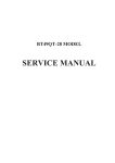
REMOVING THE CYLINDER AND PISTON
1. Remove:
• piston pin clip 햲
• piston pin 햳
• piston 햴
CAUTION:
Do not use a hammer to drive the piston pin
out.
NOTE:
• Before removing the piston pin clip, cover the
crankcase opening with a clean rag to prevent
the piston pin clip from falling into the crankcase.
• Before removing the piston pin, deburr the
piston pin clip’s groove and the piston’s pin
bore area. If both areas are deburred and the
piston pin is still difficult to remove, remove it
with the piston pin puller.
6
4
5
3
Piston pin puller
90890-01304
9
1
FW
햸
Order
1
2
3
4
5
6
7
8
9
10
11
T.R
10
11
8
7
2. Remove:
• top ring
• 2nd ring
• oil ring
12 Nm (1.2 m•kg)
NOTE:
When removing a piston ring, open the end gap
with your fingers and lift the other side of the ring
over the piston crown.
2
D
Job/Part
Q’ty
Removing the cylinder and piston
Cylinder head
Cylinder bolt
Timing chain guide (exhaust side)
Cylinder
Dowel pin
Cylinder gasket
Piston pin clip
Piston pin
Piston
Piston ring (top)
Piston ring (2nd)
Oil ring
Remarks
Remove the parts in the order listed.
Refer to “CYLINDER HEAD” section.
2
1
1
2
1
2
1
1
1
1
1
EAS00255
For installation, reverse the removal
procedure.
4 - 23
CHECKING THE CYLINDER AND PISTON
1. Check:
• piston wall
• cylinder wall
Vertical scratches → Rebore or replace the
cylinder, and replace the piston and piston
rings as a set.
4 - 24
햹
햲
EAS00008
햳
GEN
INFO
SYMBOLS
The following symbols are not relevant to every
vehicle.
Symbols 햲 to 햺 indicate the subject of each
chapter.
햲 General information
햳 Specifications
햴 Periodic checks and adjustments
햵 Engine
햶 Cooling system
햷 Carburetor
햸 Chassis
햹 Electrical system
햺 Troubleshooting
SPEC
햴
햵
CHK
ADJ
ENG
햶
햷
COOL
CARB
햸
햹
ELEC
CHAS
햺
Symbols 햻 to 헃 indicate the following.
햻 Serviceable with engine mounted
햽 Filling fluid
햾 Lubricant
햿 Special tool
헀 Tightening torque
헁 Wear limit, clearance
헂 Engine speed
헃 Electrical data
햻
TRBL
SHTG
햽
햾
햿
헀
T.
헁
헂
헃
헄
헅
헆
쎻
21
쎻
22
쎻
23
쎻
24
쎻
25
R
Symbols 헄 to 쎻
23 in the exploded diagrams indicate
the types of lubricants and lubrication points.
헄 Engine oil
헅 Gear oil
헆 Molybdenum disulfide oil
쎻
21 Wheel bearing grease
쎻
22 Lithium soap base grease
쎻
23 Molybdenum disulfide grease
Symbols 쎻
24 to 쎻
25 in the exploded diagrams
indicate the following.
쎻
24 Apply locking agent (LOCTITE®)
쎻
25 Use a new one
EAS00010
TABLE OF CONTENTS
GENERAL INFORMATION
GEN
INFO
1
SPEC
2
PERIODIC CHECKS AND
ADJUSTMENTS
CHK
ADJ
3
ENGINE OVERHAUL
ENG
4
COOL
5
CARB
6
CHAS
7
ELEC
8
TRBL
SHTG
9
SPECIFICATIONS
COOLING SYSTEM
CARBURETOR
CHASSIS
ELECTRICAL SYSTEM
TROUBLESHOOTING
GEN
INFO
1
GEN
INFO
CHAPTER 1.
GENERAL INFORMATION
SCOOTER IDENTIFICATION ........................................................................ 1-1
VEHICLE IDENTIFICATION NUMBER .................................................... 1-1
MODEL LABEL ........................................................................................ 1-1
FEATURES ................................................................................................... 1-2
OIL INDICATOR LIGHT ........................................................................... 1-2
ODOMETER/TRIPMETER READING MODE ......................................... 1-2
BATTERY VOLTAGE/FUEL GAUGE ...................................................... 1-2
THE CLOCK ............................................................................................. 1-3
AUTO-CHOKE SYSTEM ......................................................................... 1-3
IMPORTANT INFORMATION ......................................................................
PREPARATION FOR REMOVAL AND DISASSEMBLY ........................
REPLACEMENT PARTS ........................................................................
GASKETS, OIL SEALS AND O-RINGS ..................................................
LOCK WASHERS/PLATES AND COTTER PINS ...................................
BEARINGS AND OIL SEALS ..................................................................
CIRCLIPS ................................................................................................
1-4
1-4
1-4
1-4
1-5
1-5
1-5
CHECKING THE CONNECTIONS ............................................................... 1-6
SPECIAL TOOLS .......................................................................................... 1-7
SCOOTER IDENTIFICATION
GEN
INFO
EAS00015
GENERAL INFORMATION
SCOOTER IDENTIFICATION
햲
EASM0002
VEHICLE IDENTIFICATION NUMBER
The vehicle identification number 햲 is stamped
into the frame.
ZAUM0071
EASM0003
MODEL LABEL
The model label 햲 is affixed under the seat.
This information will be needed to order spare
parts.
햲
ZAUM0072
1-1
FEATURES
GEN
INFO
EASM0004
FEATURES
OIL INDICATOR LIGHT
• FUNCTION
Pulses (travel distance signals) from the speedometer are counted and cause the oil indicator light
to come on at 500 km for the first time and thereafter every 3,000 km. In this way, the light indicates
the time for oil change.
• RESETTING PROCEDURE
To reset the oil change indicator light
1) Press the “TRIP” button while turning the key to “ON”.
2) Release the button and the oil change indicator light will go off.
NOTE:
To reset the oil change indicator light before the periodic oil change interval has been reached, follow
the above procedure.
ODOMETER/TRIPMETER READING MODE
The odometer and tripmeter can be set to count in either miles or kilometers according to the following
procedure.
1) Turn the key to “ON”.
2) Press the “TRIP” button until the current mode appears in the dispaly:
“CONT” (continental) for kilometer mode and “EnGL” (English) for the mile mode.
3) Press the “TRIP” button to switch mode.
4) Press the “TRIP” button for two seconds to confirm the setting.
NOTE:
• The odometer/tripmeter reading mode can be changed any number of times while the odometer
reading is below 10, but it cannot changed anymore after the reading has reached 10.
• Switching between the mile and the kilometer mode does not change or convert the current odometer/
tripmeter reading.
BATTERY VOLTAGE/FUEL GAUGE
When the key is turned to “OFF”, the voltage/fuel gauge indicates the battery voltage.
NOTE:
If the battery voltage drops to 10V, refer to “CHECKING THE BATTERY” section in chapter 3.
When the key is turned to “ON”, the voltage/fuel gauge indicates the amount of fuel in the fuel tank
after indicating the battery voltage for two seconds.
1-2
FEATURES
GEN
INFO
THE CLOCK
• Setting the clock
To set the clock:
1) Make sure that the key is turned to “OFF”.
2) Press the “TRIP” button for two seconds and the hour display will flash.
3) Press the “TRIP” button to set the hours.
4) Press the “TRIP” button for two seconds, and the first minute digit will flash.
5) Press the “TRIP” button to set the first minute digit.
6) Press the “TRIP” button for two more seconds, and the second minute digit will flash.
7) Press the “TRIP” button to set the second minute digit.
8) Press the “TRIP” button for two seconds to set the clock.
AUTO-CHOKE SYSTEM
This system is the parallel connection of the ignitor unit circuit and the thermo switch as shown,
detecting the engine temperature, and facilitates the restarting with the warm engine.
• Circuit diagram
Ignitor unit
Main switch
Thermo
switch
Fuse
Ignition
C.P.U
Battery
Auto-choke
• Auto-choke operation
Engine condition Start with the
cold engine
Thermo switch
OFF
Crank with the
cold engine
OFF
Crank with the
warm engine
ON
Restart with the
warm engine
ON
Ignitor unit circuit OFF
Auto-choke
Activates
ON
Activates
ON
Not activate
OFF
Not activate
1-3
IMPORTANT INFORMATION
GEN
INFO
EAS00020
IMPORTANT INFORMATION
PREPARATION FOR REMOVAL AND
DISASSEMBLY
1.Before removal and disassembly, remove all
dirt, mud, dust and foreign material.
2.Use only the proper tools and cleaning equipment.
Refer to the “SPECIAL TOOLS”.
3.When disassembling, always keep mated parts
together. This includes gears, cylinders, pistons and other parts that have been “mated”
through normal wear. Mated parts must always be reused or replaced as an assembly.
4.During disassembly, clean all of the parts and
place them in trays in the order of disassembly. This will speed up assembly and allow for
the correct installation of all parts.
5.Keep all parts away from any source of fire.
EAS00021
REPLACEMENT PARTS
1.Use only genuine Yamaha and MBK parts for
all replacements. Use oil and grease recommended by Yamaha or MBK for all lubrication
jobs. Other brands may be similar in function
and appearance, but inferior in quality.
EAS00022
GASKETS, OIL SEALS AND O-RINGS
1.When overhauling the engine, replace all gaskets, seals and O-rings. All gasket surfaces,
oil seal lips and O-rings must be cleaned.
2.During reassembly, properly oil all mating
parts and bearings and lubricate the oil seal
lips with grease.
1-4
IMPORTANT INFORMATION
GEN
INFO
EAS00023
LOCK WASHERS / PLATES AND COTTER
PINS
1.After removal, replace all lock washers / plates
햲 and cotter pins. After the bolt or nut has
been tightened to specification, bend the lock
tabs along a flat of the bolt or nut.
햲
EAS00024
BEARINGS AND OIL SEALS
1.Install bearings and oil seals so that the manufacturer’s marks or numbers are visible. When
installing oil seals, lubricate the oil seal lips
with a light coat of lithium soap base grease.
Oil bearings liberally when installing, if appropriate.
햳 Oil seal
햳
CAUTION:
Do not spin the bearing with compressed air
because this will damage the bearing surfaces.
햲
햲 Bearing
EAS00025
CIRCLIPS
1.Before reassembly, check all circlips carefully
and replace damaged or distorted circlips.
Always replace piston pin clips after one use.
When installing a circlip 햲, make sure the
sharp-edged corner 햳 is positioned opposite
the thrust 햴 that the circlip receives.
햵 Shaft
햲
햴
햳
햵
1-5
CHECKING THE CONNECTIONS
GEN
INFO
EAS00026
CHECKING THE CONNECTIONS
Check the leads, couplers, and connectors for
stains, rust, moisture, etc.
1.Disconnect:
• lead
• coupler
• connector
2.Check:
• lead
• coupler
• connector
Moisture → Dry with an air blower.
Rust/stains → Connect and disconnect several times.
3.Check:
• all connections
Loose connection → Connect properly.
햲
NOTE:
If the pin 햲 on the terminal is flattened, bend it
up.
4.Connect:
• lead
• coupler
• connector
+
NOTE:
Make sure all connections are tight.
-
5.Check:
• continuity
(with the pocket tester)
Pocket tester
90890-03112
+
NOTE:
• If there is no continuity, clean the terminals.
• When checking the wire harness, perform steps
1 to 3.
• As a quick remedy, use a contact revitalizer
available at most part stores.
1-6
-
SPECIAL TOOLS
GEN
INFO
EAS00027
SPECIAL TOOLS
The following special tools are necessary for complete and accurate tune-up and assembly. Use
only the appropriate special tools as this will help prevent damage caused by the use of inappropriate
tools or improvised techniques. Special tools, part numbers or both may differ depending on the
country.
When placing an order, refer to the list provided below to avoid any mistakes.
Tool No.
90890-01083
90890-01084
Tool name/usage
Slide hammer bolt (M6)
Weight
These tools are used to remove or
installing the rocker arms shafts.
90890-01235
Rotor holding tool
This tool is used to remove the flywheel
magneto.
90890-01268
90890-01403
Ring nut wrench 햲
Steering nut wrench 햳
These tools are used to loosen and tighten
the steering ring nuts.
90890-01294
90890-01326
Damper rod holder
T-handle
These tools are used for disassembling
or assembling the front fork.
90890-01304
Piston pin puller
This tool is used to remove the piston pins.
90890-01312
Fuel level gauge
This tool is used to measure the fuel level
in the float chamber.
90890-01337
90890-01464
Clutch spring holder
Clutch spring holder arm
These tools are used for removing the nut
with holding the compression spring.
1-7
Illustration
SPECIAL TOOLS
Tool No.
90890-01367
90890-01368
Tool name/usage
Fork seal driver weight
Frok seal driver attachment
These tools are used when installing the
fork seal.
90890-01701
Sheave holder
This tool is used to hold the secondary
sheave when removing or installing the
nut.
90890-03111
Valve adjusting tool
This tool is necessary for adjusting valve
clearance.
90890-03112
Pocket Tester
This instrument is invaluable for checking
the electrical system.
90890-03113
Engine tachometer
This tool is needed for detecting the
engine rpm.
90890-03141
Timing light
This tool is needed for detecting ignition
timing.
90890-04019
90890-04108
Valve spring compressor
Attachment
These tools are used when removing or
installing the valve and the valve spring.
90890-04116
Valve guide remover
This tool is used to remove the valve
guide.
1-8
GEN
INFO
Illustration
SPECIAL TOOLS
Tool No.
90890-04117
Tool name/usage
Valve guide installer
This tool is needed to install the valve
guide spring.
90890-04118
Valve guide reamer
This tool is used to rebore the valve guide.
90890-06754
Ignition checker
This instrument is necessary for checking
the ignition system components.
90890-85505
Yamaha bond No. 1215
This sealant (bond) is used for crankcase
mating surface, etc.
90890-03081
Compression gauge
This gauge is used to measure the engine
compression.
1-9
GEN
INFO
Illustration
SPEC
2
SPEC
CHAPTER 2.
SPECIFICATIONS
GENERAL SPECIFICATIONS ...................................................................... 2-1
MAINTENANCE SPECIFICATIONS ............................................................. 2-4
ENGINE ................................................................................................... 2-4
CHASSIS ................................................................................................. 2-8
ELECTRICAL ......................................................................................... 2-10
CONVERSION TABLE ............................................................................... 2-12
GENERAL TIGHTENING TORQUE SPECIFICATIONS ............................ 2-13
TIGHTENING TORQUES ........................................................................... 2-14
TIGHTENING TORQUES (ENGINE) ..................................................... 2-14
TIGHTENING TORQUES (CHASSIS) ................................................... 2-16
LUBRICATION POINTS AND LUBRICANT TYPES .................................. 2-17
ENGINE ................................................................................................. 2-17
CHASSIS ............................................................................................... 2-18
COOLING SYSTEM DIAGRAMS ............................................................... 2-19
LUBRICATION DIAGRAMS ....................................................................... 2-21
CABLE ROUTING ....................................................................................... 2-23
GENERAL SPECIFICATIONS
SPEC
SPECIFICATIONS
GENERAL SPECIFICATIONS
Item
XN125 [XN150]
Dimensions
Overall length
Overall width
Overall height
Seat height
Wheelbase
Minimum ground clearance
Minimum turning radius
1.868 mm
740 mm
1.096 mm
777 mm
1.315 mm
105 mm
1.800 mm
Weight
Wet (with oil and a full fuel tank)
Dry (without oil and fuel)
123 kg
116 kg
Engine
Engine type
Cylinder arrangement
Displacement
Bore x stroke
Compression ratio
Standard compression pressure (at sea level)
Starting system type
Lubrication system
Liquid cooled 4-stroke, SOHC
Forward inclined single cylinder
124 cm3 [152 cm3]
53.7 x 54.8 mm [59.5 x 54.8 mm]
11: 01
1.400kPa/500r/min (14kgf/cm2/500r/min)
Electric starter
Wet sump
Oil capacity
Engine oil
-20
-10
Temp.
0
10
20
30
40
10W/30
10W/40
API STANDARD:
SE or higher grade
20W/40
20W/50
1.2 L
1.4 L
Periodic oil change
Total amount
Final gear case oil
Total amount
0.15 L
Coolant system
Radiator capacity (including all routes)
Coolant reservoir capacity
<from low to full level>
1.1 L
0.35 L
<0.25 L>
Air filter type
Dry element
Fuel
Recommended fuel
Fuel tank capacity
Regular unleaded gasoline
10 L
2-1
GENERAL SPECIFICATIONS
Item
SPEC
XN125 [XN150]
Carburator
Type/quantity
Manufacturer
TK 5DS/1 [TK 5KD/1]
TEIKEI
Spark plug
Type
Manufacturer
Spark plug gap
CR8E
NGK
0.5~0.7 mm
Clutch type
Dry, centrifugal automatic
Transmission
Primary reduction system
Primary reduction ratio
Secondary reduction system
Secondary reduction ratio
Transmission type
Operation
Helical gear
40/15 (2.666)
Spur gear
44/12 (3.666) [42/14 (3)]
V-belt automatic
Centrifugal automatic type
Chassis
Frame type
Caster angle
Trail
Steel tube backbone
26°
80 mm
Tyre
Tyre type
Size (front)
Size (rear)
Manufacturer (front)
Manufacturer (rear)
Type (front)
Type (rear)
Tubeless
120/70-12
120/70-12
METZELER
METZELER
7-TEEN
7-TEEN
Tyre pressure (cold)
Maximum load*-except motorcycle
Loading condition A
Front
Rear
Loading condition B
Front
Rear
180 kPa (1.80 kgf/cm2)
200 kPa (2.00 kgf/cm2)
Front wheel
Wheel type
Rim size
Cast wheel
12 x MT3.50
Rear wheel
Wheel type
Rim size
Cast wheel
12 x MT3.50
187 kg
200 kPa (2.00 kgf/cm2)
220 kPa (2.20 kgf/cm2)
2-2
GENERAL SPECIFICATIONS
Item
SPEC
XN125 [XN150]
Brake
Front brake type
Front brake operation
Rear brake type
Rear brake operation
Single disc brake
Right hand operation
Drum brake
Left hand operation
Suspension
Front suspension
Rear suspension
Telescopic fork
Unit swing
Shock absorber
Front fork type
Rear shock absorber assembly type
Coil spring/oil damper
Coil spring/oil damper
Wheel travel
Front wheel travel
Rear wheel travel
90 mm
80 mm
Electrical
Ignition system type
Charging system type
Battery type
Battery voltage/capacity
C.D.I
Flywheel magneto
CB7L-B2 or YB7L-B2
12V 8Ah
Headlight type
Bulbs (voltage/wattage x quantity)
Headlight
Position light
Brake/tail light
Front flasher light
Rear flasher light
Meter light
High beam indicator light
Turn indicator light
Coolant temperature warning light
Bulb
12V 35W/35W x 2
12V 5W x 1
12V 21W/5W x 1
12V 21W x 2
12V 10W x 2
12V 1.2W x 2
12V 1.2W x 1
12V 1.2W x 2
12V 1.2W x 1
Amperage for fuses
Main fuse
Radiator fan fuse
20 A
7.5 A
2-3
MAINTENANCE SPECIFICATIONS
SPEC
MAINTENANCE SPECIFICATIONS
ENGINE
*[XN150]
Item
Standard
Limit
Cylinder head
Warp limit
•••
0.03 mm
Cylinder
Bore size
Out of round limit
53.700 ~ 53.705 mm [59.500 ~ 59.505mm]*
•••
•••
0.05 mm
Camshaft
Drive system
Cam dimensions
Intake “A”
“B”
“C”
Exhaust “A”
“B”
“C”
Camshaft runout limit
Chain drive (left)
C
A
B
30.811 ~ 30.911 mm
25.145 ~ 25.245 mm
5.666 m
30.811 ~ 30.911 mm
25.152 ~ 25.252 mm
5.659 m
•••
Cam chain
Cam chain type/No. of links
82 RH2005/94
Rocker arm/rocker armshaft
Rocker arm inside diameter
Rocker shaft outside diameter
12.000 ~ 12.018 mm
11.981 ~ 11.991 mm
Valve,valve seat, valve guide
Valve clearance (cold)
IN
EX
Valve dimensions
•••
30.711 mm
25.045 mm
•••
30.711 mm
25.052 mm
•••
0.03 mm
•••
12.030mm
11.950 mm
0.10 ~ 0.14 mm
0.16 ~ 0.20 mm
•••
•••
C
B
A
“A” head diameter
IN
EX
“B” face width
IN
EX
“C” seat width
IN
EX
Stem outside diameter
IN
EX
Guide inside diameter
IN
EX
Stem-to-guide clearence IN
EX
Stem runout limit
Valve seat width
IN
EX
Face width
26.9 ~ 27.1 mm
22.9 ~ 23.1 mm
2.687 ~ 3.252 mm
2.687 ~ 3.252 mm
0.9 ~ 1.1 mm
0.9 ~ 1.1 mm
4.475 ~ 4.490 mm
4.460 ~ 4.475 mm
4.500 ~ 4.512 mm
4.500 ~ 4.512 mm
0.01 ~ 0.037 mm
0.025 ~ 0.052
•••
0.9 ~ 1.1 mm
0.9 ~ 1.1 mm
2-4
Seat width
•••
•••
•••
•••
•••
1.6 mm
4.445 mm
4.430 mm
4.542 mm
4.542 mm
0.08 mm
0.10 mm
0.01 mm
1.6 mm
1.6 mm
MAINTENANCE SPECIFICATIONS
SPEC
*[XN150]
Item
Valve spring
Inner spring
Free length
Set length (valve closed)
Compressed pressure
Tilt limit
Standard
IN/EX
IN/EX
IN/EX
IN/EX
Piston
Piston to cylinder
clearence
Piston size “D”
Measuring point “H”
D
Piston pin bore inside diameter
Piston pin outside diameter
Piston rings
Top ring:
Type
End gap (installed)
Side clearance (installed)
2 nd ring:
Type
End gap (installed)
Side clearence (installed)
Oil ring:
End gap (installed)
H
Limit
41.94 mm
37.5 mm
45.1 ~ 50.9 N
2.5° / 1.9 mm
39.84 mm
•••
•••
•••
0.025 ~ 0.035 mm
0.15 mm
53.670 ~ 53.687 mm [59.470 ~ 59.487 mm]*
•••
4.5 mm
•••
15.002 ~ 15.013 mm
15.045 mm
14.991 ~ 15.000 mm
14.975 mm
Barrel
0.15 ~ 0.25 mm
0.03 ~ 0.07 mm
•••
0.50 mm
0.12 mm
Taper
0.15 ~ 0.30 mm
0.02 ~ 0.06 mm
•••
0.65 mm
0.12 mm
0.2 ~ 0.7 mm
•••
Crankshaft
Crank width “A”
Runout limit “C”
Big end side clearance “D”
47.950 ~ 48.000 mm
•••
0.15 ~ 0.45 mm
Automatic centrifugal clutch
Clutch shoe thickness
Clutch housing inside diameter
Weight outside diameter
Clutch-in revolution
Clutch-stall revolution
2.0 mm
120 mm [135 mm]*
20.0 mm
3,550 ~ 4,050 rpm [3,250 ~ 3,750 rpm]*
5,900 ~ 6,900 rpm [5,600 ~ 6,400 rpm]*
V-Belt
V-belt width
22 mm
2-5
•••
0.03 mm
•••
1.0 mm
120.5 [135.5 ]*
19.5 mm
•••
•••
19 mm
MAINTENANCE SPECIFICATIONS
SPEC
*[XN150]
Item
Standard
Limit
Carburetor
Type
I.D mark
Main jet (M.J)
Main air jet (M.A.J)
Jet needle (J.N)
Pilot air jet (P.A.J.1)
Needle jet (N.J)
Pilot jet (P.J)
Pilot screw (P.S)
Valve seat size (V.S)
Starter jet 1 (G.S.1)
Float height (F.L)
Engine idle speed
TK 5DS [TK 5KD]*
•••
#116 [#114]*
ø1.0 [ø1.4]*
4E31 (3/5) [4E32 (3/5)]*
ø1.30
2.590
#38 [#36]
2 1/4 ~ 2 3/4 [2 ~ 4]*
ø2.00
#0.45
5 ~ 6 mm
1.600 ~ 1.800 rpm
Oil pump
Type
Tip clearence
Side clearance
Housing and rotor clearence
Trochoid
•••
•••
•••
Radiator
Type
Width/height thickness
Radiator cap opening pressure
Reservoir tank capacity
Cooling fin with electric fan
170 / 282 / 29 mm
90 ~ 110 kPa
0.35 L
•••
•••
•••
•••
Thermostatic valve
Manufacturer
Valve opening temperature
Valve full open temperature
ANGLI
82 ±3°C
95 ±3°C
•••
•••
•••
2-6
•••
•••
•••
•••
•••
•••
•••
•••
•••
•••
•••
•••
•••
0.15 mm
0.15 mm
0.17 mm
MAINTENANCE SPECIFICATIONS
Item
SPEC
Size
Crankshaft oil seal (left)
Crankshaft oil seal (right)
Crankshaft oil seal (right)
Camshaft bearing (left)
Camshaft bearing (right)
Starter clutch bearing
Primary drive gear bearing (left)
Primary drive gear bearing (right)
Primary drive gear oil seal
Main axle bearing (left)
Main axle bearing (right)
Drive axle bearing (left)
Drive axle bearing (right)
Drive axle oil seal
22 x 32 x 7
19 x 30 x 8 (Reinforced)
19 x 30 x 8 (Double lips)
20 x 42 x 12
15 x 32 x 9
17 x 35 x 10
25 x 52 x 15
17 x 40 x 12
25 x 42 x 6 (Double lips)
15 x 25 x 12 (Needle bearing)
12 x 37 x 12
17 x 47 x 14 (Sphere)
22 x 50 x 14 (Sphere)
32 x 52 x 7
2-7
MAINTENANCE SPECIFICATIONS
SPEC
MAINTENANCE SPECIFICATIONS
CHASSIS
Item
Standard
Limit
Steering system
Steering bearing type
No./size of steel balls Upper
Lower
Ball bearing
15 pcs 4.75 mm
15 pcs 4.75 mm
•••
•••
•••
Front suspension
Front fork travel
Spring rate
(K1)
Stroke
(K1)
Oil capacity
Oil grade
Inner tube outer diameter
Optional spring
90 mm
11 N/mm
0 ~ 90 mm
125 cm3
SAE20
33 mm
No
•••
•••
•••
•••
•••
•••
•••
Rear suspension
Shock absorber travel
Fitting length
Spring rate
(K1)
(K2)
Stroke
(K1)
(K2)
80 mm
229 mm
18 N/mm
53.5 N/mm
0 ~ 60 mm
60 ~ 80 mm
•••
•••
•••
•••
•••
•••
Front wheel
Type
Rim size
Rim material
Rim runout limit Radial
Lateral
Cast wheel
MT 3.50 x 12
Aluminium
•••
•••
•••
•••
•••
1 mm
0.5 mm
Rear wheel
Type
Rim size
Rim material
Rim runout limit Radial
Lateral
Cast wheel
MT 3.50 x 12
Aluminium
•••
•••
•••
•••
•••
1 mm
0.5 mm
Front disc brake
Type
Disc outside diameter x thickness
Pad thickness
Master cylinder inside diameter
Caliper cylinder outside diameter
Brake fluid type
Single
220 x 4.5 mm
4 mm
11 mm
32 mm
DOT #3 or DOT #4
•••
•••
0.8 mm
•••
•••
•••
Rear drum brake
Type
Drum inside diameter
Shoe thickness
Shoe spring free length
Leading, trailing
130 mm
4.0 mm
54 mm
2-8
•••
130.5 mm
2.0 mm
•••
MAINTENANCE SPECIFICATIONS
Item
Brake lever
Brake lever free play (front)
Brake lever free play (rear)
Throttle cable free play
Standard
10 ~ 20 mm
10 ~ 20 mm
1.5 ~ 3.0 mm
2-9
SPEC
Limit
•••
•••
•••
MAINTENANCE SPECIFICATIONS
SPEC
MAINTENANCE SPECIFICATIONS
ELECTRICAL
Item
Ignition timing
Ignition timing (B.T.D.C)
Advanced timing (B.T.D.C)
Advanced type
T.C.I
Pickup coil resistance/color
Source coil resistance/color
Standard
Limit
10° at 1.700 rpm
32° at 5.000 rpm
Digital
•••
•••
•••
248 ~ 372 Ω at 20°C /
white / red-white / blue
720 ~ 1080 Ω at 20°C /
green/white - brown/black
•••
•••
Ignition coil
Minimum spark gap
Primary winding resistance
Secondary winding resistance
6 mm
0.32 ~ 0.48 Ω at 20°C
5.7 ~ 8.5 kΩ at 20°C
•••
•••
•••
Spark plug cap
Type
Resistance
Resin type
10 kΩ
•••
•••
Charging system
Type
Normal output
Stator coil resistance/color
Flywheel magneto
14 V 10.5 A at 5.000 rpm
0.6 ~ 0.9 Ω at 20°C/white - white - white
•••
•••
Rectifier/regulator
Model/manufacturer
No load regulated voltage
Capacity
Withstand voltage
14.5 V
25 A
200 V
•••
•••
•••
Battery
Specific gravity
1.280
•••
Constant mesh type
•••
Electric starting system
Type
Starter motor:
Operation voltage
Output
Armature coil resistance
Brush overall length
Brush quantity
Spring force
Commutator diameter
Mica undercut (depth)
12 V
0.3 kW
0.0306 ~ 0.0374 Ω at 20°C
10 mm
2
5.6 ~ 8.3 N
22 mm
1.5 mm
Starter relay
Model/manufacturer
Amperage rating
Coil winding resistance
9768054/JIDECO
100 A
4.2 ~ 4.6 Ω at 20°C
2-10
•••
•••
•••
3.5 mm
•••
•••
21 mm
•••
•••
•••
•••
MAINTENANCE SPECIFICATIONS
Item
Standard
SPEC
Limit
Horn
Model/manufacturer
Maximum amperage
YF-12 / NIKKO
3A
•••
•••
Flasher relay
Flasher frequency
80 ~ 160 cycle/min
•••
Fuel gauge
Model/manufacturer
Sender unit resistance - full
- empty
25.33.06/MAXIMA
4 ~ 10 Ω
90 ~ 100 Ω
•••
•••
•••
Circuit breaker
Main
Radiagtor fan fuse
20 A x 1 pcs
7.5 A x 1 pcs
•••
•••
2-11
CONVERSION TABLE
SPEC
AS00028
CONVERSION TABLE
All specification data in this manual are listed in SI and METRIC UNITS.
Use this table to convert METRIC unit data to IMPERIAL unit data.
Ex.
METRIC
MULTIPLIER
IMPERERIAL
** mm x
0.03937
=
** in
2 mm x
0.03937
=
0.08 in
CONVERSION TABLE
METRIC TO IMPERIAL
Metric unit
Multiplier
Imperial unit
Torque
m•kg
m•kg
cm•kg
cm•kg
7.233
86.794
0.0723
0.8679
ft•lb
in•lb
ft•lb
in•lb
Weight
kg
g
2.205
0.03527
lb
oz
Speed
km/h
0.6214
mph
Distance
km
m
m
cm
mm
0.6214
3.281
1.094
0.3937
0.03937
mi
ft
yd
in
in
Volume/ Capacity
cc (cm3)
cc (cm3)
L (liter)
L (liter)
0.03527
0.06102
0.8799
0.2199
oz(IMP liq.)
cu•in
qt(IMP liq.)
gal(IMP liq.)
Misc.
kg/mm
kg/cm2
Centigrade (°C)
55.997
14.2234
9/5+32
lb/in
psi(lb/in2)
Fahrenheit (°F)
2-12
GENERAL TIGHTENING TORQUE SPECIFICATIONS
SPEC
EAS00029
GENERAL TIGHTENING TORQUE SPECIFICATIONS
This chart specifies tightening torques for standard fasteners with a standard ISO thread pitch.
Tightening torque specifications for special components or assemblies are provided for each chapter
of this manual. To avoid warpage, tighten multi-fastener assemblies in a crisscross pattern and
progressive stages until the specified tightening torque is reached. Unless otherwise specified,
tightening torque specifications require clean, dry threads. Components should be at room
temperature.
A
A
(nut)
B
(bolt)
10 mm
6 mm
12 mm
8 mm
15
1.5
14 mm
10 mm
30
3.0
17 mm
12 mm
55
5.5
19 mm
14 mm
85
8.5
22 mm
16 mm
130
13.0
B
A: Width across flats
B: Thread diameter
2-13
General tightening
torques
Nm
m•kg
6
0.6
TIGHTENING TORQUES
SPEC
TIGHTENING TORQUES
ENGINE
Item
Oil check bolt
Spark plug
Cylinder, water drain bolt
Cylinder head and cylinder
Cylinder head and cylinder
Cylinder and crankcase
Camshaft bearing stopper
Camchain guide
Valve adjuster nut
Camshaft pinion bolt
Camshaft tensionner
Rocker shaft securing plate
Thermostatic valve cover
Water pump housing cover
Water pump housing
Water pump housing
Thermostatic valve cover
Oil pump
Engine drain plug
Inlet manifold on cylinder head
Air filter cover
Exhaust pipe stud bolt on cylinder
Muffler on bracket
Muffler bracket on crankcase
Muffler protector
Crankcase (left)
Cover, crankcase 1
Cover, crankcase 2
Cover, oil pump
Duct, air
Cover, magneto
Cylinder head stud bolt
Transmission oil drain plug
Engine oil drain plug
Cover, crankcase 3
Starter idle gear plate
Primary fixed sheave
Clutch carrier assembly
Clutch housing
Fastener
Bolt
Bolt
Nut
Bolt
Bolt
Bolt
Bolt
Nut
Bolt
Bolt
Bolt
Bolt
Bolt
Bolt
Bolt
Bolt
Bolt
Bolt
Bolt
Nut
Bolt
Bolt
Bolt
Bolt
Bolt
Bolt
Bolt
Bolt
Bolt
Stud
Plug
Plug
Bolt
Bolt
Nut
Nut
Nut
2-14
Thread
size
M6
M10
M6
M8
M6
M6
M6
M6
M5
M8
M6
M6
M6
M6
M6
M6
M6
M6
M35
M6
M6
M6
M8
M8
M6
M6
M6
M6
M6
M6
M6
M8
M8
M8
M6
M6
M14
M36
M12
Q'ty
1
1
1
4
2
1
1
1
2
1
2
1
1
4
2
1
2
3
1
2
8
2
2
2
2
8
11
6
3
3
3
4
1
1
2
2
1
1
1
Tightening
torque
Nm
m•kg
9
13
8
22
12
12
12
6.5
6.5
30
10
10
9
10
7
7
9
65
32
10
6.5
11
27
27
4.5
9
10
10
6.5
7
7
13
22
22
6.5
7
60
90
55
0.9
1.3
0.8
2.2
1.2
1.2
1.2
0.65
0.65
0.3
1.0
1.0
0.9
1.0
0.7
0.7
0.9
6.5
3.2
1.0
0.65
1.1
2.7
2.7
0.45
0.9
1.0
1.0
0.65
0.7
0.7
1.3
2.2
2.2
0.65
0.7
6.0
9.0
5.5
Remarks
TIGHTENING TORQUES
Item
Fastener
Rear brake shoes pin pivot
Thermo unit
Coolant drain bolt on cylinder
Starter motor
Rotor
Nut
Bolt
Bolt
Nut
Stator
Bolt
2-15
Thread
size
M10
Pt 1/8
M6
M6
M12
M16
M16
M6
Q'ty
1
1
1
2
1
1
1
3
SPEC
Tightening
torque
Nm
m•kg
120
75
8
65
70
225
225
70
12.0
7.5
0.8
6.5
7.0
22.5
22.5
7.0
Remarks
TIGHTENING TORQUES
SPEC
TIGHTENING TORQUES
CHASSIS
Item
Frame with engine bracket
Engine bracket 2 with 3
E/G bracket with E/G (with main stand)
Reinforcement tail
Rear cushion with frame
Rear cushion with engine
Steering shaft
Handle with steering shaft
Master cylinder with handle
Seat lock
Box with frame
Box with reinforcement tail
Carrier with frame
Carrier with reinforcement tail
Footrest board with frame
Mud guard with frame
Fender on front fork
Cover handle with handle
Mainstand
Rear footrest
Front wheel axle
Rear wheel axle
Rear brake cam lever
Rear brake pin pivot
Front caliper on front fork
Front brake disc on wheel
Union bolt with caliper
Union bolt with master cylinder
Fastener
Bolt
Bolt
Bolt
Bolt
Nut
Nut
Nut
Nut
Bolt
Bolt
Bolt
Bolt
Bolt
Bolt
Bolt
Bolt
Bolt
Bolt
Nut
Nut
Nut
Nut
Nut
Nut
Bolt
Bolt
Bolt
Bolt
2-16
Thread
size
M10
M10
M10
M6
M10
M8
M25
M10
M6
M6
M6
M6
M8
M8
M6
M6
M6
M5
M10
M8
M12
M14
M6
M10
M8
M8
M10
M10
Q'ty
1
2
2
4
1
1
3
1
2
2
2
2
1
2
4
2
3
2
2
2
1
1
1
1
2
4
1
1
Tightening
torque
Nm
m•kg
42
55
32
6.5
32
18
4.2
5.5
3.2
0.65
3.2
1.8
60
8.5
4
8
8
19
19
4
7
4
4.5
42
14
70
104
14
12
23
23
23
23
6.0
0.85
0.4
0.8
0.8
1.9
1.9
0.4
0.7
0.4
0.45
4.2
1.4
7.0
10.4
1.4
1.2
2.3
2.3
2.3
2.3
Remarks
See chapter 7
“STEERING
HEAD”
LUBRICATION POINTS AND LUBRICANT TYPES
SPEC
EAS00031
LUBRICATION POINTS AND LUBRICANT TYPES
ENGINE
Lubrication Point
Symbol
Oil seal lips
O-ring (Except V-belt drive unit)
Cylinder head tightening nut mounting surface
Crankshaft pin outside
Connecting rod big end thrust surface
Rotary filter inner surface
Drive gear inner surface
Cam chain outside sprocket inner surface
Piston pin
Piston outside and ring groove
Camshaft cam profile
Valve stem (IN, EX)
Valve stem end (IN, EX)
Rocker shaft
Valve rocker arm inner surface
Shaft
Shaft (Oil pump assembly)
Gasket (Oil pump assembly)
Holder
Idle gear 1 thrust surfaces
Shaft 1
Idle gear 2 thrust surfaces
Idle gear 2 inner surface
Main axle thrust surfaces
Crankcase mating surfaces
Yamaha bond No. 1215
Crankcase breather plug
Stator grommet
Yamaha bond No. 1215
Suction pipe
2-17
LUBRICATION POINTS AND LUBRICANT TYPES
SPEC
EAS00032
CHASSIS
Lubrication Point
Symbol
Front wheel oil seal lips (left/right)
Steering head pipe bearing (upper/lower)
Tube guide (throttle grip) inner surface
Brake cable (brake lever)
Brake lever and lever holder bolt sliding surface
Sidestand sliding surface
Centerstand sliding surface and mounting bolt
Centerstand stopper pivot shaft
Brake cam pivot shaft and cam surface
2-18
COOLING SYSTEM DIAGRAMS
SPEC
EAS00033
COOLING SYSTEM DIAGRAMS
A Pass the hose under inlet manifold.
Radiator cap
Radiator
Radiator fan
Thermo switch
Coolant tank
Water pump
Cylinder
Inlet manifold
A
2-19
COOLING SYSTEM DIAGRAMS
SPEC
EAS00033(bis)
COOLING SYSTEM DIAGRAMS
Radiator
Radiator fan
Radiator cap
Coolant tank
Water pump
Thermostat
A Pass the hose between radiator and radiator
filler hose.
A
2-20
LUBRICATION DIAGRAMS
SPEC
EAS00034
LUBRICATION DIAGRAMS
1Lubrication of the cylinder head
Cylinder head
Cylinder
Crankcase
2Lubrication of the crankshaft
Crankshaft
1
2
2-21
LUBRICATION DIAGRAMS
SPEC
EAS00034(bis)
LUBRICATION DIAGRAMS
1Oil flow
Cylinder head
Cylinder
Oil pump
2Lubrication table
A Oil pressure flow
B Oil return flow
1
2
A
B
Camshaft
Crankshaft
Cylinder head
Rocker arm
Oil pump
Oil strainer
Crankcase
2-22
Connecting rod
CABLE ROUTING
SPEC
EAS00035
CABLE ROUTING
Thermo switch wire
Seat lock cable
Speedometer wire
Main switch wire
Seat lock cable adjuster
Radiator
Fan
Headlight and front flasher connector
Front fork assembly
Wire harness
Horn
Horn wire
Rear brake cable
Throttle cable
Band switch
A Make the wire harness getting out here.
B Place the speedometer wire as shown.
C Pass the thermo switch lead between the
hoses.
B
C
FA
FA
A
A
A
A-A
5~10 mm
2-23
CABLE ROUTING
Starter motor
CDI unit
rectifier/Regulator
CDI magneto wire
Ignition coil assembly
Footrest board
Starter relay
Battery ground
Wire harness
SPEC
Seat lock assembly
Fuel tank
Wire lead
Mud guard
Fuel cock
A Place the wire as shown.
B Place the sidestand wire as shown (option).
C Apply grease on stater motor connector/
terminal.
A-A
5~10 mm
A
C
D-D
C-C
A
10
~1
D
D
mm
A
5~10 mm
B-B
C
B
1
C
B
B
6
2-24
SPEC
CABLE ROUTING
Battery
Starter relay
Frame
Fuses box
Relay
Sender
Fuel pipe
21 Engine air breather
22 Fuel cock
23 Seat lock assembly
A Connection for anti-thelf (option)
B Place the Starter motor ground as shown.
C Pass the carburetor breather hose between
air duct and air filter case.
Rear left flasher
Rear brake cable adjuster
Rear brake cable
Fuel overflowed pipe
Fan
Radiator
Main switch
Sidestand wire (option)
Fueal gauge wire
Rear right flasher
Taillight
Seat lock cable
Throttle cable
5
6
14
13
15
7
12
8
18
17
13
16
20
21
4
C
3
20
2
B
19
3
9
22
23
10
1
11
A
2-25
CABLE ROUTING
SPEC
A Glue the handlebar grip.
B Install the handlebar switch as shown.
Right handlebar switches
Inner handlebar cover
Left handlebar switches
Rear brake lever
Front handlebar cover
Master cylinder
Front brake lever
B-B
A-A
C-C
view D
B
30¡
1.5 ~ 3 mm
A
D
A
BC
A
2 ~ 3 mm
BC
2-26
SPEC
CABLE ROUTING
A Pass wires behind the turn signal relay bracket
B Clip all wires and cables all together
C Install the wire harness behind the turn signal
relay bracket.
Master cylinder
Inner handlebar cover
Speedometer assembly
Rear brake cable
Throttle cable
Front brake hose
Wire harness
Handlebar
Speedometer coupler
Front handlebar cover
A
B
B
A
F
C
A
C
D
B
D
B-B
view F
C
A-A
D-D
C-C
E
G
E
G
G-G
RIGHT
FRONT
LEFT
2-27
E-E
CHK
ADJ
3
CHK
ADJ
CHAPTER 3.
PERIODIC CHECKS AND ADJUSTMENTS
INTRODUCTION ............................................................................................ 3-1
PERIODIC MAINTENANCE AND LUBRICATION INTERVALS .................. 3-1
COVER AND PANEL .................................................................................... 3-3
SIDE COVERS AND SEAT ...................................................................... 3-3
FRONT COVER, INNER PANEL AND INNER FRONT COVER ............. 3-5
FOOTREST BOARD AND UNDER COVER ............................................ 3-6
HANDLEBAR COVERS ........................................................................... 3-7
ENGINE ......................................................................................................... 3-8
ADJUSTING THE VALVE CLEARANCE ................................................. 3-8
ADJUSTING THE ENGINE IDLING SPEED ............................................ 3-9
ADJUSTING THE THROTTLE CABLE FREE PLAY ............................. 3-10
CHECKING THE SPARK PLUG ............................................................ 3-11
CHECKING THE IGNITION TIMING ..................................................... 3-12
TRANSMISSION OIL REPLACEMENT ................................................. 3-13
MEASURING THE COMPRESSION PRESSURE ................................ 3-14
CHECKING THE ENGINE OIL LEVEL .................................................. 3-15
CHANGING THE ENGINE OIL .............................................................. 3-16
MEASURING THE ENGINE OIL PRESSURE ....................................... 3-17
CLEANING THE AIR FILTER ELEMENT .............................................. 3-18
CLEANING THE V-BELT CASE AIR FILTER ELEMENT ...................... 3-18
CHECKING THE FUEL AND VACUUM HOSES ................................... 3-19
EXHAUST SYSTEM INSPECTION ....................................................... 3-19
CHECKING THE COOLANT LEVEL ..................................................... 3-20
CHANGING THE COOLANT ................................................................. 3-21
INSPECTING THE COOLANT SYSTEM ............................................... 3-24
CHASSIS ..................................................................................................... 3-25
CHECKING THE FRONT BRAKE LEVER FREE PLAY ........................ 3-25
ADJUSTING THE REAR BRAKE .......................................................... 3-25
CHECKING THE BRAKE FLUID LEVEL ............................................... 3-26
CHECKING THE BRAKE PADS ............................................................ 3-27
CHECKING THE BRAKE SHOES ......................................................... 3-27
CHECKING THE BRAKE HOSES ......................................................... 3-27
BLEEDING THE HYDRAULIC BRAKE SYSTEM .................................. 3-28
CHECKING AND ADJUSTING THE STEERING HEAD ........................ 3-29
CHECKING THE FRONT FORK ............................................................ 3-31
INSPECTING THE REAR SHOCK ABSORBER ................................... 3-32
CHECKING THE TYRES ....................................................................... 3-32
CHECKING THE WHEELS .................................................................... 3-35
CHECKING AND LUBRICATING THE CABLES ................................... 3-35
LUBRICATING THE LEVERS AND PEDALS ........................................ 3-36
LUBRICATING THE CENTERSTAND ................................................... 3-36
CHK
ADJ
ELECTRICAL SYSTEM ............................................................................... 3-37
CHECKING THE BATTERY .................................................................. 3-37
CHECKING THE FUSES ....................................................................... 3-40
REPLACING THE HEADLIGHT BULBS AND THE FRONT TURN
SIGNAL LIGHT BULBS .......................................................................... 3-41
REPLACING THE REAR TURN SIGNAL LIGHT BULBS ...................... 3-42
REPLACING THE TAIL/BRAKE LIGHT BULBS .................................... 3-43
ADJUSTING THE HEADLIGHT BEAMS ............................................... 3-44
ADJUSTING THE DIGITAL CLOCK ...................................................... 3-44
PERIODIC CHECKS AND ADJUSTMENTS
CHK
ADJ
EAS00036
PERIODIC CHECKS AND ADJUSTMENTS
INTRODUCTION
This chapter includes all information necessary to perform recommended checks and adjustments. If
followed, these preventive maintenance procedures will ensure more reliable vehicle operation, a
longer service life and reduce the need for costly overhaul work. This information applies to vehicles
already in service as well as to new vehicles that are being prepared for sale. All service technicians
should be familiar with this entire chapter.
EAS00037
PERIODIC MAINTENANCE AND LUBRICATION INTERVALS
No.
ITEM
1 * Fuel line
2
Spark plug
3 * Valves
4
Air filter
5
V-belt (crankcase) air filter
6 * Battery
7 * Front brake (disc)
8 * Rear brake (drum)
9 * Brake hose
10 * Wheels
11 * Tires
12 * Wheel bearings
13 * Steering bearings
14
Chassis fasteners
15
Centerstand
CHECK, MAINTENANCE AND LUBRICATION
ODMETER READING (x1,000km)
0.5
• Check fuel hoses and vacuum hose for cracks
or damage.
• Check condition.
• Clean, regap.
• Replace.
• Check valve clearance.
• Adjust.
• Clean.
• Replace.
• Clean.
• Check electrolyte level and specific gravity.
• Make sure that the breather hose is properly
routed.
• Check operation, fluid level and vehicle for fluid
leakage.(See NOTE on page 6-4)
• Replace brake pads.
• Check operation and adjust brake lever freeplay.
• Replace brake shoes.
• Check for cracks or damage.
• Replace.
• Check runout and for damage.
• Check tread depth and for damage.
• Replace if necessary.
• Check air pressure.
• Correct if necessary.
• Checks bearing for looseness or damage.
• Check bearing play and steering for roughness.
• Lubricate with lithium soap base grease.
• Make sure that all nuts, bolts and screws are
properly tightened.
• Check operation.
• Lubricate.
3-1
6
12
18
24
Annual
check
앀
앀
앀
앀
앀
앀
앀
앀
앀
앀
앀
앀
앀
앀
앀
앀
앀
앀
앀
앀
앀
앀
앀
앀
앀
앀
앀
앀
앀
앀
앀
앀
앀
앀
앀
앀
앀
Whenever necessary
앀
앀
앀
Whenever necessary
앀
앀
앀
Every 4 years.
앀
앀
앀
앀
앀
앀
앀
앀
앀
앀
앀
앀
앀
앀
앀
앀
앀
앀
앀
앀
앀
앀
앀
앀
앀
앀
앀
앀
PERIODIC CHECKS AND ADJUSTMENTS
No.
ITEM
16 * Front fork
17 * Rear shock absorber
assembly
18 * Carburetor
19 * Engine oil
20 * Engine oil filter strainer
21 * Final gear oil
22 * Coolant system
23 * V-belt
24
Moving parts and cables
25 * Light, signals and switches
CHECK, MAINTENANCE AND LUBRICATION
• Check operation and for oil leakage.
• Check operation and shock absorber for oil
leakage.
• Check engine idling speed and starter operation.
• Change.
• Clean.
• Check vehicle for oil leakage
• Change.
• Check coolant level and vehicle for coolant
leakage.
• Change.
• Check wear and damage.
• Replace.
• Lubricate.
• Check operation.
• Adjust headlight beam.
CHK
ADJ
ODMETER READING (x1,000km)
0.5
앀
앀
앀
6
12
18
24
앀
앀
앀
앀
앀
앀
앀
앀
앀
앀
앀
앀
앀
앀
앀
Every 3,000 km.
앀
앀
앀
앀
앀
앀
앀
앀
Every 3 years.
앀
앀
앀
앀
Every 18,000 km.
앀
앀
앀
앀
앀
앀
앀
앀
앀
* Since these items require special tools, data and technical skills, they should be serviced by
a Yamaha or MBK dealer.
NOTE:
• The air filters need more frequent service if you are riding in unusually wet or dusty areas.
• Brake fluid replacement:
1. Replace the brake fluid after disassembling the master cylinder or caliper cylinder.
2. Check the brake fluid level and add fluid as required.
3. Replace the brake hoses every four years or if cracked or damaged.
3-2
앀
앀
앀
앀
앀
Annual
check
CHK
ADJ
COVER AND PANEL
EASM0005
COVER AND PANEL
SIDE COVERS AND SEAT
2
T.R
8 Nm (0.8 m¥kg)
18.5 Nm (1.85 m¥kg)
T.R
4
6
6
5
7
3
T.R
7 Nm (0.7 m¥kg)
1
8
D
FW
T.R
Order
I
1
2
II
3
III
4
IV
5
6
Job/Part
Q’ty
Removing the side covers
Remove:
Battery cover
Box and seat assembly
Seat axle circlip
Seat axle
Seat
Gasket
Unplug:
Fuel tank overflow pipe
Remove:
Rear carrier
Disconnect:
Taillight coupler
Rear flasher light (left and right)
7 Nm (0.7 m¥kg)
Remarks
Remove the parts in the order listed.
1
1
1
1
1
1
1
1
1
1
3-3
NOTE:
Open the seat to remove it.
CHK
ADJ
COVER AND PANEL
2
T.R
8 Nm (0.8 m¥kg)
18.5 Nm (1.85 m¥kg)
T.R
4
6
6
5
7
3
T.R
7 Nm (0.7 m¥kg)
1
8
D
FW
T.R
Order
V
7
8
Job/Part
Q’ty
Remove:
Side cover (right)
Side cover (left)
7 Nm (0.7 m¥kg)
Remarks
1
1
For installation, reverse the removal
procedure.
3-4
CHK
ADJ
COVER AND PANEL
EASM0007
FRONT COVER, INNER PANEL AND INNER FRONT COVER
2
7 Nm (0.7 m kg)
T.R
7 Nm (0.7 m kg)
T.R
T.R
7 Nm (0.7 m kg)
6
3
1
5
7
4
T.R
T.R
7 Nm (0.7 m kg)
7 Nm (0.7 m kg)
FW
Order
1
2
3
II
4
III
5
IV
6
7
D
Job/Part
Removing the front cover, inner
panel and the inner front cover
Remove:
Coolant tank cover
Main switch cap
Helmet holder
Untight:
Front cover
Disconnect
Headlight lead
Remove:
Front cover / Radiator panel
Inner panel
Q’ty
Remarks
Remove the parts in the order listed.
1
1
1
1
1
1/1
1
For installation, reverse the removal
procedure.
3-5
CHK
ADJ
COVER AND PANEL
EASM0008
FOOTREST BOARD AND UNDER COVER
1
7 Nm (0.7 m kg)
T.R
T.R
4 Nm (0.4 m kg)
1
3
2
T.R
13.5 Nm (1.35 m kg)
6
4
7 Nm (0.7 m kg)
T.R
5
D
FW
Order
I
II
1
2
3
4
5
6
Job/Part
Q’ty
Removing the footrest board
and under cover
Remove:
Side covers
2
Inner panel
1
Remove:
Footrest
Battery
Fuses box
Starter relay
Under cover
Side under cover/footrest board
assembly
Remarks
Remove the parts in the order listed.
2
1
Refer to “SIDE COVERS AND SEAT”
section.
Refer to “FRONT COVER, INNER PANEL
AND INNER FRONT COVER” section.
1 washer/1 spring washer/1 washer
1
1
1/1
For installation, reverse the removal
procedure.
3-6
COVER AND PANEL
CHK
ADJ
EASM0009
HANDLEBAR COVERS
T.R
T.R
7 Nm (0.7 m kg)
2
4.5 Nm (0.45 m kg)
1
3
T.R
4.5 Nm (0.45 m kg)
D
FW
Order
I
1
II
2
III
3
Job/Part
Q’ty
Removing the handlebar covers
Remove:
Front handlebar cover
Disconnect:
Speedometer assy’ lead
Remove:
Inner handlebar cover
Remarks
Remove the parts in the order listed.
1
1
For installation, reverse the removal
procedure.
3-7
ADJUSTING THE VALVE CLEARANCE
CHK
ADJ
EAS00049
ENGINE
ADJUSTING THE VALVE CLEARANCE
The following procedure applies to all of the
valves.
NOTE:
• Valve clearance adjustment should be made
on a cold engine, at room temperature.
• When the valve clearance is to be measured or
adjusted, the piston must be at top dead center
(TDC) on the compression stroke.
1. Remove:
• Battery cover
• Seat
• Side covers
• Box
Refer to “SIDE COVERS AND SEAT” section.
• Spark plug
• Plug on magneto cover
• Valve cover “inlet”
• Valve cover “exhaust”
2. Measure:
• valve clearance
Out of specification → Adjust.
Valve clearance (cold)
Intake valve
0.10 ~ 0.14 mm
Exhaust valve
0.16 ~ 0.20 mm
b
왔왔왔왔왔왔왔왔왔왔왔왔왔왔왔왔왔왔왔왔왔왔왔왔왔왔왔왔왔
a. Turn the crankshaft counterclockwise.
b. When the piston is at TDC on the compression stroke, align the mark a on the generator
rotor with the stationary pointer b on the
crankcase.
c. Measure the valve clearance with a thickness
gauge .
Out of specification → Adjust.
a
왖왖왖왖왖왖왖왖왖왖왖왖왖왖왖왖왖왖왖왖왖왖왖왖왖왖왖왖왖
3-8
ADJUSTING THE VALVE CLEARANCE/
ADJUSTING THE ENGINE IDLING SPEED
CHK
ADJ
3. Adjust:
• valve clearance
왔왔왔왔왔왔왔왔왔왔왔왔왔왔왔왔왔왔왔왔왔왔왔왔왔왔왔왔왔
a. Loosen the locknut .
b. Insert a thickness gauge between the end of
the adjusting screw and the valve tip.
c. Turn the adjusting screw in or out until the
specified valve clearance is obtained.
→ Valve clearance is
decreased.
Turning out → Valve clearance is
increased.
Turning in
Valve adjusting tool 90890-01311
Hold the adjusting screw to prevent it from
moving and tighten the locknut to specification.
T.
R
Locknut
6.5 Nm (0.65 m•kg)
d. Measure the valve clearance again.
e. If the valve clearance is still out of specification,
repeat all of the valve clearance adjustment
steps until the specified clearance is obtained.
왖왖왖왖왖왖왖왖왖왖왖왖왖왖왖왖왖왖왖왖왖왖왖왖왖왖왖왖왖
4. Install:
• Box
• Side covers
• Seat
• Battery cover
Refer to “SIDE COVERS AND SEAT” section.
EASM0010
ADJUSTING THE ENGINE IDLING SPEED
NOTE:
Prior to adjusting the engine idling speed, the air
filter element should be clean, and the engine
should have adequate compression.
1. Start the engine and let it warm up for several
minutes.
3-9
ADJUSTING THE ENGINE IDLING SPEED/
ADJUSTING THE THROTTLE CABLE FREE PLAY
CHK
ADJ
2. Attach:
• engine tachometer
(onto the spark plug lead of the cylinder)
Engine tachometer 90890-03113
3. Measure:
• engine idling speed
Out of specification → Adjust.
Engine idling speed
1,400 ~ 1,800 r / min
4. Adjust:
• engine idling speed
왔왔왔왔왔왔왔왔왔왔왔왔왔왔왔왔왔왔왔왔왔왔왔왔왔왔왔왔왔
a. Turn the pilot screw in until it is lightly seated.
b. Turn the pilot screw out the specified number
of turns.
Pilot screw setting
XN 125: 2 1/4 ~ 2 3/4
XN 150: 2 ~ 4
c. Turn the throttle stop screw in or out until the
specified engine idling speed is obtained.
왖왖왖왖왖왖왖왖왖왖왖왖왖왖왖왖왖왖왖왖왖왖왖왖왖왖왖왖왖
→ Engine idling speed is
increased.
Turning out → Engine idling speed is
decreased.
Turning in
5. Adjust:
• throttle cable free play
Refer to “ADJUSTING THE THROTTLE CABLE FREE PLAY”.
Throttle cable free play
(at the flange of the throttle grip)
1.5 ~ 3 mm
EASM0011
ADJUSTING THE THROTTLE CABLE FREE
PLAY
NOTE:
Prior to adjusting the throttle cable free play, the
engine idling speed should be adjusted.
3-10
ADJUSTING THE THROTTLE CABLE FREE PLAY /
CHECKING THE SPARK PLUG
CHK
ADJ
1. Check:
• throttle cable free play Out of specification → Adjust.
Throttle cable free play
(at the flange of the throttle grip)
1.5 ~ 3 mm
2. Adjust:
• throttle cable free play
ZAUM0051
NOTE:
When the throttle is opened, the accelerator
cable is pulled.
왔왔왔왔왔왔왔왔왔왔왔왔왔왔왔왔왔왔왔왔왔왔왔왔왔왔왔왔왔
a. Turn the adjusting nut in or out until the
specified throttle cable free play is obtained.
Turning in → Throttle cable free play is
increased.
Turning out → Throttle cable free play is
decreased.
WARNING
After adjusting the throttle cable free play,
start the engine and turn the handlebar to
the right and to the left to ensure that this
does not cause the engine idling speed to
change.
왖왖왖왖왖왖왖왖왖왖왖왖왖왖왖왖왖왖왖왖왖왖왖왖왖왖왖왖왖
EAS00060
ZAUM0035
CHECKING THE SPARK PLUG
1. Disconnect:
• spark plug cap 2. Remove:
• spark plug
CAUTION:
Before removing the spark plug, blow away
any dirt accumulated in the spark plug well
with compressed air to prevent it from falling
into the cylinder.
3. Check:
• spark plug type
Incorrect → Change.
Spark plug type (manufacturer)
CR8E (NGK)
3-11
CHECKING THE SPARK PLUG/
CHECKING THE IGNITION TIMING
CHK
ADJ
4. Check:
• electrodes Damage/wear → Replace the spark plug.
• insulator Abnormal color → Replace the spark plug.
Normal color is medium-to-light tan.
5. Clean:
• spark plug
(with a spark plug cleaner or wire brush)
6. Measure:
• spark plug gap (with a wire gauge)
Out of specification → Regap.
Spark plug gap
0.5 ~ 0.7 mm
ZAUM0037
7. Install:
• spark plug
T.R
13 Nm (1.3m•kg)
NOTE:
Before installing the spark plug, clean the spark
plug and gasket surface.
8. Connect:
• spark plug cap
EAS00061
CHECKING THE IGNITION TIMING
NOTE:
Prior to checking the ignition timing, check the
wiring connections of the entire ignition system.
Make sure all connections are tight and free of
corrosion.
1. Attach:
• timing light • engine tachometer (onto the spark plug lead of the cylinder)
Timing light
90890-03141
Engine tachometer
90890-03113
3-12
CHECKING THE IGNITION TIMING/
TRANSMISSION OIL REPLACEMENT
CHK
ADJ
2. Check:
• ignition timing
왔왔왔왔왔왔왔왔왔왔왔왔왔왔왔왔왔왔왔왔왔왔왔왔왔왔왔왔왔
a. Start the engine, warm it up for several minutes, and then let it run at the specified engine
idling speed.
Engine idling speed
1,400 ~ 1,800 r/min
a
b
b. Check that the mark a is within the required
firing range b on the timing plate.
Incorrect firing range → Check the ignition
system.
NOTE:
The ignition timing is not adjustable.
왖왖왖왖왖왖왖왖왖왖왖왖왖왖왖왖왖왖왖왖왖왖왖왖왖왖왖왖왖
TRANSMISSION OIL REPLACEMENT
NOTE:
Make sure the scooter is upright when replacing
the oil.
1. Stand the scooter on a level surface.
2. Start the engine for several minutes to warm
it up and then stop.
3. Place an oil pan under the crankcase.
4. Remove:
• oil filler cap
• drain bolt Drain the oil.
5. Tighten:
• drain bolt
22 Nm (2.2m•kg)
6. Fill:
• crankcase
T.R
Recommended oil:
SAE 10W30 motor oil (API, SE)
Oil quantity:
0.15L
CAUTION:
Wipe any spilled oil off the tire or the wheel.
7. Install:
• oil filler cap • O-ring 8. Start the engine for several minutes to warm
it up and check for the oil leakage.
3-13
MEASURING THE COMPRESSION PRESSURE
CHK
ADJ
EAS00067
MEASURING THE COMPRESSION
PRESSURE
NOTE:
Insufficient compression pressure will result in a
loss of performance.
1. Measure:
• valve clearance
Out of specification → Adjust
Refer to “ADJUSTING THE VALVE CLEARANCE” section.
2. Start the engine, warm it up for several minutes, and then turn it off.
3. Disconnect:
• spark plug cap
4. Remove:
• spark plug
CAUTION:
Before removing the spark plug, use
compressed air to blow away any dirt
accumulated in the spark plug well to prevent
it from falling into the cylinder.
5. Install:
• compression gauge Compression gauge
90890-03081
6. Measure:
• compression pressure
Out of specification → Refer to steps (c) and
(d).
• Compression pressure (at sea level)
Minimum
1,120 kPa (11.20 kg/cm2)
Standard
1,400 kPa (14.00 kg/cm2)
왔왔왔왔왔왔왔왔왔왔왔왔왔왔왔왔왔왔왔왔왔왔왔왔왔왔왔왔왔
a. Set the main switch to “ON”.
b. With the throttle wide open, crank the engine
until the reading on the compression gauge
stabilizes.
WARNING
To prevent sparking, ground the spark plug
lead before cranking the engine.
3-14
MEASURING THE COMPRESSION PRESSURE/
CHECKING THE ENGINE OIL LEVEL
CHK
ADJ
c. If the compression pressure is above the
maximum specification, check the cylinder
head, valve surfaces, and piston crown for
carbon deposits.
Carbon deposits → Remove.
d. If the compression pressure is below the
minimum specification, squirt a few drops of
oil into the cylinder and measure again.
Refer to the following table.
왖왖왖왖왖왖왖왖왖왖왖왖왖왖왖왖왖왖왖왖왖왖왖왖왖왖왖왖왖
Compression pressure
(with oil applied into the cylinder)
Reading
Diagnosis
Higher than
Piston wear or damage
without oil
→ Repair.
Piston ring(s), valves,
Same as
cylinder head gasket or
without oil
piston possibly
defective → Repair.
7. Install:
• spark plug
13 Nm (1.3m•kg)
8. Connect:
• spark plug cap T.R
EAS00070
CHECKING THE ENGINE OIL LEVEL
1. Stand the scooter on a level surface.
ZAUM0035
NOTE:
• Place the scooter on a suitable stand.
• Make sure the scooter is upright.
2. Start the engine, warm it up for several minutes, and then turn it off.
NOTE:
• Before checking the engine oil level, wait a few
minutes until the oil has settled.
• Do not screw the dipstick in when inspecting
the oil level.
3. Check:
• engine oil level
The engine oil level should be between the
minimum level mark and maximum level
mark .
Below the minimum level mark → Add the
recommended engine oil to the proper level.
ZAUM0038
3-15
CHECKING THE ENGINE OIL LEVEL/
CHANGING THE ENGINE OIL
-20° -10°
0°
10° 20° 30°
Recommended oil
Refer to the chart for the engine oil
grade which is best suited for
certain atmospheric temperatures.
API standard
SE or higher grade
(Non-friction modified)
40° 50°C
SAE 10W/30
SAE 10W/40
SAE 15W/40
SAE 20W/40
SAE 20W/50
CHK
ADJ
CAUTION:
Do not allow foreign materials to enter the
crankcase.
NOTE:
Before checking the engine oil level, wait a few
minutes until the oil has settled.
4. Start the engine, warm it up for several minutes, and then turn it off.
5. Check the engine oil level again.
NOTE:
Before checking the engine oil level, wait a few
minutes until the oil has settled.
EASM0012
ZAUM0040
T.R
ZAUM0040
32 Nm (3.2m•kg)
CHANGING THE ENGINE OIL
1. Start the engine and let it warm up for several
minutes.
2. Turn off the engine and place an oil pan under
the engine.
3. Remove:
• Oil filler plug
• Drain plug • Compression spring • Oil strainer • O-ring
Drain the crankcase of its oil.
4. Install:
• O-ring • Compression spring • Oil strainer • Drain plug 32 Nm (3.2m•kg)
• Oil filler plug
5. Fill:
• Crankcase
T.R
Oil quantity:
1.2 L
6. Check:
• Engine oil level
Refer to “CHECKING THE ENGINE OIL
LEVEL” section.
3-16
CHECKING THE ENGINE OIL/
MEASURING THE ENGINE OIL PRESSURE/
CHK
ADJ
7. Reset:
• engine oil warning circuit 왔왔왔왔왔왔왔왔왔왔왔왔왔왔왔왔왔왔왔왔왔왔왔왔왔왔왔왔왔
a. Press the “TRIP” button while turning the
key to “ON”
b. Release the “TRIP” button and oil indicator
light will go off
NOTE:
• If the oil is change before the oil indicator light
comes on (i.e. before the 3,000 km oil change
interval is reached), be sure to reset the oil
indicator light after changing oil, so that it will
indicate the next 3,000 km oil remplacement at
the correct time.
• To reset the oil change indicator light before the
periodic oil change interval has been reached,
follow the above procedure.
ZAUM0007
왖왖왖왖왖왖왖왖왖왖왖왖왖왖왖왖왖왖왖왖왖왖왖왖왖왖왖왖왖
EASM0013
T.R
10 Nm (1.0 m kg)
MEASURING THE ENGINE OIL PRESSURE
1. Remove:
• side covers
Refer to “SIDE COVERS AND SEAT” section.
2. Inspect:
• oil pressure
왔왔왔왔왔왔왔왔왔왔왔왔왔왔왔왔왔왔왔왔왔왔왔왔왔왔왔왔왔
a. Slightly loosen the oil check bolt .
b. Start the engine and keep it idling until the oil
begins to seep from the oil check bolt.
If no oil comes out after one minute, turn the
engine off so it will not seize.
c. Check oil passages and oil pump for damage
or leakage.
d. Start the engine after solving the problem(s),
and recheck the oil pressure.
e. Tighten the oil check bolt to specification.
T.
R
Oil check bolt
10Nm (1.0m•kg)
CAUTION:
• Start the engine and check the oil pressure
with the oil check bolt loosened.
• Do not apply at high speeds more than
specified when checking the pressure.
NOTE:
Wipe any spilled oil off the engine.
왖왖왖왖왖왖왖왖왖왖왖왖왖왖왖왖왖왖왖왖왖왖왖왖왖왖왖왖왖
3-17
CLEANING THE AIR FILTER ELEMENT/
CLEANING THE V-BELT CASE AIR FILTER ELEMENT
ZAUM0046
CHK
ADJ
EAS00086
CLEANING THE AIR FILTER ELEMENT
1. Remove:
• air filter case cover 2. Clean:
• air filter element Apply compressed air to the outer surface of
the air filter element.
3. Check:
• air filter element Damage → Replace.
4. Install:
• air filter element • air filter case cover CAUTION:
Never operate the engine without the air filter
element installed. Unfiltered air will cause
rapid wear of engine parts and may damage
the engine. Operating the engine without the
air filter element will also affect the
carburetor tuning, leading to poor engine
performance and possible overheating.
NOTE:
When installing the air filter element into the air
filter case cover, make sure their sealing surfaces
are aligned to prevent any air leaks.
EAS00091
ZAUM0048
CLEANING THE V-BELT CASE AIR FILTER
ELEMENT
1. Remove:
• V-belt case air filter cover • V-belt case air filter element 2. Clean:
• V-belt case air filter element Apply compressed air to the outer surface of
the primary fixed sheave air filter element.
3. Check:
• V-belt case air filter element
Damage → Replace.
CAUTION:
Since the V-belt case air filter element is a dry
type, do not let grease or water contact it.
ZAUM0050
4. Install:
• V-belt case air filter element
7 Nm (0.7m•kg)
• V-belt case air filter cover
T.R
3-18
CHECKING THE FUEL AND VACUUM HOSES/
EXHAUST SYSTEM INSPECTION
CHK
ADJ
EAS00096
CHECKING THE FUEL AND VACUUM
HOSES
The following procedure applies to all of the fuel
and vacuum hoses.
1. Remove:
• Seat
• Box
Refer to “SIDE COVERS AND SEAT” section.
2. Check:
• vacuum hose
• fuel hose
Cracks/damage → Replace.
Loose connection → Connect properly.
3. Install:
• Box
• Seat
Refer to “SIDE COVERS AND SEAT” section.
EASM0014
EXHAUST SYSTEM INSPECTION
1. Remove:
• Side covers
Refer to “SIDE COVERS AND SEAT” section.
2. Inspect:
11 Nm (1.1 m•kg)
• Nut (exhaust pipe)
Loose/Damage → Tighten/Replace.
• Gasket (exhaust pipe)
Exhaust gas leaks → Tighten/Replace
3. Inspect:
27 Nm (2.7 m•kg)
• Bolt (mufler)
Loose/Damage → Tighten/Replace
T.R
T.R
3-19
CHECKING THE COOLANT LEVEL
CHK
ADJ
EAS00103
CHECKING THE COOLANT LEVEL
1. Stand the scooter on a level surface.
NOTE:
Place the scooter on a suitable stand.
Make sure the scooter is upright.
2. Remove:
• Coolant tank cover Refer to “FRONT COVER, INNER PANEL
AND INNER FRONT COVER” section.
ZAUM0044
3. Check:
• coolant level
The coolant level should be between the
maximum level mark and minimum level
mark .
Below the minimum level mark → Add the
recommended coolant to the proper level.
CAUTION:
• Adding water instead of coolant lowers the
antifreeze content of the coolant. If water
is used instead of coolant check, and if
necessary, correct the antifreeze concentration of the coolant.
• Use only distilled water. However, if distilled
water is not available, soft water may be
used.
4. Start the engine, warm it up for several minutes, and then turn it off.
5. Check:
• coolant level
NOTE:
Before checking the coolant level, wait a few
minutes until it settles.
6. Install:
• Coolant tank cover
Refer to “FRONT COVER, INNER PANEL
AND INNER FRONT COVER” section.
3-20
CHANGING THE COOLANT
CHK
ADJ
EAS00105
CHANGING THE COOLANT
1. Remove:
• Side covers
• Seat
• Rear carrier
• Box
Refer to “SIDE COVERS AND SEAT” section.
• Front cover
• Inner panel
Refer to “FRONT COVER, INNER PANEL
AND INNER FRONT PANEL” section.
2. Disconnect:
• coolant reservoir hose
3. Drain:
• coolant
(from the coolant reservoir)
4. Remove:
• radiator cap
WARNING
A hot radiator is under pressure. Therefore,
do not remove the radiator cap when the
engine is hot. Scalding hot fluid and steam
may be blown out, which could cause
serious injury. When the engine has cooled,
open the radiator cap as follows:
Place a thick rag or a towel over the radiator
cap and slowly turn the radiator cap
counterclockwise toward the detent to allow
any residual pressure to escape. When the
hissing sound has stopped, press down on
the radiator cap and turn it counterclockwise
to remove.
The following procedure applies to all of the
coolant drain bolts and copper washers.
5. Remove:
• coolant drain bolt (water pump)
(along with the copper washer)
• coolant drain bolt (engine)
(along with the copper washer)
6. Drain:
• coolant
(from the engine and radiator)
3-21
CHANGING THE COOLANT
CHK
ADJ
7. Check:
• copper washer (coolant drain bolt-engine )
• copper washer (coolant drain bolt-water
pump)
Damage → Replace.
8. Install:
• coolant drain bolt (engine)
T.R
10 Nm (1.0m•kg)
• coolant drain bolt (water pump)
T.R
10 Nm (1.0m•kg)
9. Connect:
• coolant reservoir hose
10. Fill:
• cooling system
(with the specified amount of the
recommended coolant)
Recommended antifreeze
High-quality ethylene glycol
antifreeze containing corrosion
inhibitors for aluminum engines
Mixing ratio
1:1 (antifreeze:water)
Quantity
Total amount
1.1 L
Coolant reservoir capacity
0.35 L
Handling notes for coolant
Coolant is potentially harmful and should be
handled with special care.
WARNING
• If coolant splashes in your eyes, thoroughly
wash them with water and consult a doctor.
• If coolant splashes on your clothes, quickly
wash it away with water and then with soap
and water.
• If coolant is swallowed, induce vomiting
and get immediate medical attention.
3-22
CHANGING THE COOLANT
CHK
ADJ
CAUTION:
• Adding water instead of coolant lowers the
antifreeze content of the coolant. If water
is used instead of coolant check, and if
necessary, correct the antifreeze concentration of the coolant.
• Use only distilled water. However, if distilled
water is not available, soft water may be
used.
• If coolant comes into contact with painted
surfaces, immediately wash them with
water.
• Do not mix different types of antifreeze.
ZAUM0044
11. Install:
• radiator cap
12. Fill:
• coolant reservoir
(with the recommended coolant to the maximum level mark )
13. Install:
• coolant reservoir cap
14. Start the engine, warm it up for several
minutes, and then stop it.
15. Check:
• coolant level
Refer to “CHECKING THE COOLANT LEVEL”
section.
NOTE:
Before checking the coolant level, wait a few
minutes until the coolant has settled.
16. Install:
• Inner panel
• Front cover
Refer to “FRONT COVER, INNER PANEL
AND INNER FRONT PANEL” section.
• Box
• Rear carrier
• Seat
• Side covers
Refer to “SIDE COVERS AND SEAT” section.
3-23
INSPECTING THE COOLANT SYSTEM
CHK
ADJ
EASM0015
INSPECTING THE COOLANT SYSTEM
1. Inspect:
• Radiator
• Filler hose (radiator)
• Outlet hose (radiator)
• Pipe
• Outlet hose (radiator)
Cracks/Damage → Replace
Refer to “COOLING SYSTEM” section in
chapter 5.
3-24
CHECKING THE FRONT BRAKE LEVER FREE PLAY/
ADJUSTING THE REAR BRAKE
CHK
ADJ
EASM0016
CHASSIS
CHECKING THE FRONT BRAKE LEVER
FREE PLAY
1. Check:
• brake lever free play Out of specification → check the front brake
system.
Refer to “FRONT BRAKE” section in chapter
7.
ZAUM0055
Brake lever free play (at the end of
the brake lever)
10 ~ 20 mm
WARNING
A soft or spongy feeling in the brake lever
can indicate the presence of air in the brake
system. Before the vehicle is operated, the
air must be removed by bleeding the brake
system. Air in the brake system will
considerably reduce braking performance
and could result in loss of control and
possibly an accident. Therefore, check and,
if necessary, bleed the brake system.
EAS00114
ADJUSTING THE REAR BRAKE
1. Check:
• brake lever free play a
Out of specification → Adjust.
a
Brake lever free play
10 ~ 20 mm
2. Adjust:
• brake lever free play
• Handlebar side
• Rear wheel side
ZAUM0056
왔왔왔왔왔왔왔왔왔왔왔왔왔왔왔왔왔왔왔왔왔왔왔왔왔왔왔왔왔
a. Turn the adjusting nut in direction A or B
until the specified brake lever free play is
obtained.
Direction A → Brake lever free play is
increased.
Direction B → Brake lever free play is
decreased.
B
ZAUM0057
A
3-25
ADJUSTING THE REAR BRAKE/
CHECKING THE BRAKE FLUID LEVEL
CHK
ADJ
CAUTION:
After adjusting the brake lever free play,
make sure there is no brake drag.
왖왖왖왖왖왖왖왖왖왖왖왖왖왖왖왖왖왖왖왖왖왖왖왖왖왖왖왖왖
EAS00116
CHECKING THE BRAKE FLUID LEVEL
1. Stand the scooter on a level surface.
NOTE:
• Place the scooter on a suitable stand.
• Make sure the scooter is upright.
2. Check:
• brake fluid level
Below the minimum level mark → Add the
recommended brake fluid to the proper level.
Recommended brake fluid
DOT#3 or DOT#4
�
A Front brake
A
ZAUM0060
WARNING
• Use only the designated brake fluid. Other
brake fluids may cause the rubber seals to
deteriorate, causing leakage and poor
brake performance.
• Refill with the same type of brake fluid that
is already in the system. Mixing brake fluids
may result in a harmful chemical reaction,
leading to poor brake performance.
• When refilling, be careful that water does
not enter the reservoir. Water will
significantly lower the boiling point of the
brake fluid and could cause vapor lock.
CAUTION:
Brake fluid may damage painted surfaces
and plastic parts. Therefore, always clean up
any spilt brake fluid immediately.
NOTE:
In order to ensure a correct reading of the brake
fluid level, make sure the top of the reservoir is
horizontal.
3-26
CHECKING THE BRAKE PADS/CHECKING THE BRAKE
SHOES/
CHECKING THE BRAKE HOSES
CHK
ADJ
EASM0017
A
ZAUM0058
CHECKING THE BRAKE PADS
The following procedure applies to all of the
brake pads.
1. Operate the brake.
2. Check:
• brake pad thickness Less than specification → Replace the brake
pads as a set.
Refer to “FRONT BRAKE” section in chapter
7.
Brake pad thickness wear limit
0.8 mm
A Front brake
EAS00126
ZAUM0059
CHECKING THE BRAKE SHOES
1. Operate the brake.
2. Check:
• wear indicator Reaches the wear limit line → Replace the
brake shoes as a set.
Refer to “REAR WHEEL AND BRAKE” section
in chapter 7.
EAS00131
CHECKING THE BRAKE HOSES
The following procedure applies to all of the
brake hoses and brake hose clamps.
1. Check:
• brake hose
Cracks/damage/wear → Replace.
2. Check:
• brake hose clamp
Loose → Tighten the clamp bolt.
3. Hold the motorcycle upright and apply the
brake several times.
4. Check:
• brake hose
Activate the brake several times.
Brake fluid leakage → Replace the damaged
hose.
Refer to “FRONT WHEEL AND BRAKE DISC”
and “REAR WHEEL AND BRAKE” section in
chapter 7.
3-27
BLEEDING THE HYDRAULIC BRAKE SYSTEM
CHK
ADJ
EAS00133
BLEEDING THE HYDRAULIC BRAKE SYSTEM
WARNING
Bleed the hydraulic brake system whenever:
• the system is disassembled,
• a brake hose is loosened, disconnected or
replaced,
• the brake fluid level is very low,
• brake operation is faulty.
NOTE:
• Be careful not to spill any brake fluid or allow the
brake master cylinder reservoir to overflow.
• When bleeding the hydraulic brake system,
make sure there is always enough brake fluid
before applying the brake. Ignoring this
precaution could allow air to enter the hydraulic
brake system, considerably lengthening the
bleeding procedure.
• If bleeding is difficult, it may be necessary to let
the brake fluid settle for a few hours. Repeat the
bleeding procedure when the tiny bubbles in
the hose have disappeared.
1. Bleed:
• hydraulic brake system
왔왔왔왔왔왔왔왔왔왔왔왔왔왔왔왔왔왔왔왔왔왔왔왔왔왔왔왔왔
346002(a)
a. Fill the brake fluid reservoir to the proper level
with the recommended brake fluid.
b. Install the brake master cylinder reservoir
diaphragm.
c. Connect a clear plastic hose tightly to the
bleed screw .
d. Place the other end of the hose into a container.
e. Slowly squeeze the brake lever several times.
f. Fully squeeze the brake lever without releasing it.
g. Loosen the bleed screw.
NOTE:
Loosening the bleed screw will release the
pressure and cause the brake lever to contact
the throttle grip.
h. Tighten the bleed screw and then release the
brake lever.
3-28
BLEEDING THE HYDRAULIC BRAKE SYSTEM/
CHECKING AND ADJUSTING THE STEERING HEAD
CHK
ADJ
i. Repeat steps (e) to (h) until all of the air
bubbles have disappeared from the brake
fluid in the plastic hose.
j. Tighten the bleed screw to specification.
T.
R
Bleed screw
6 Nm (0.6 m•kg)
k. Fill the brake fluid reservoir to the proper level
with the recommended brake fluid.
Refer to “CHECKING THE BRAKE FLUID
LEVEL” section.
WARNING
After bleeding the hydraulic brake system,
check the brake operation .
왖왖왖왖왖왖왖왖왖왖왖왖왖왖왖왖왖왖왖왖왖왖왖왖왖왖왖왖왖
EAS00148
CHECKING AND ADJUSTING THE
STEERING HEAD
1. Stand the scooter on a level surface.
WARNING
Securely support the scooter so that there
is no danger of it falling over.
NOTE:
Place the scooter on a suitable stand so that the
front wheel is elevated.
2. Check:
• steering head
Grasp the bottom of the front fork legs and
gently rock the front fork.
Binding/looseness → Adjust the steering
head.
3. Remove:
• Handlebar cover
Refer to “HANDLEBAR COVERS” section.
• Handlebar
Refer to “HANDLEBAR” section in chapter 7.
4. Adjust:
• steering head
3-29
CHECKING AND ADJUSTING THE STEERING HEAD
CHK
ADJ
왔왔왔왔왔왔왔왔왔왔왔왔왔왔왔왔왔왔왔왔왔왔왔왔왔왔왔왔왔
a. Remove the lock washer , the upper ring
nut , the center ring nut and the rubber
washer.
b. Loosen the lower ring nut and then tighten
it to specification with the ring nut wrench .
NOTE:
Set the torque wrench at a right angle to the ring
nut wrench.
Steering nut wrench
90890-01403
T.
R
Lower ring nut (initial tightening
torque)
38 Nm (3.8 m•kg)
c. Loosen the lower ring nut completely and
then tighten it to specification with a ring nut
wrench .
WARNING
Do not overtighten the lower ring nut.
T.
R
Lower ring nut (final tightening
torque)
22 Nm (2.2 m•kg)
d. Check the steering head for looseness or
binding by turning the front fork all the way in
both directions. If any binding is felt, remove
the lower bracket and check the upper and
lower bearings.
Refer to “STEERING HEAD” section in
chapter 7.
e. Install the rubber washer.
f. Install the centre ring nut .
g. Finger tighten the centre ring nut, then align
the slots of both ring nuts. If necessary, hold
the lower ring nut and tighten the centre
ring nut until their slots are aligned.
h. Install the lock washer .
NOTE:
Make sure the lock washer tabs sit correctly in
the ring nut slots.
i. Hold the lower and centre ring nuts with a
exhaust and ring nut wrench and tighten the
upper ring nut with a ring nut wrench.
3-30
CHECKING AND ADJUSTING THE STEERING HEAD/
CHECKING THE FRONT FORK
CHK
ADJ
Ring nut wrench
90890-01268
T.
R
Upper ring nut
75 Nm (7.5 m•kg)
왖왖왖왖왖왖왖왖왖왖왖왖왖왖왖왖왖왖왖왖왖왖왖왖왖왖왖왖왖
5. Install:
• Handlebar
Refer to “HANDLEBAR” section in chapter 7.
• Handlebar cover
Refer to “HANDLEBAR COVERS” section.
EAS00151
CHECKING THE FRONT FORK
1. Stand the scooter on a level surface.
WARNING
Securely support the scooter so that there
is no danger of it falling over.
3115
2. Check:
• inner tube
Damage/scratches → Replace.
• oil seal
Oil leakage → Replace.
3. Hold the scooter upright and apply the front
brake.
4. Check:
• front fork operation
Push down hard on the handlebar several
times and check if the front fork rebounds
smoothly.
Rough movement → Repair.
Refer to “FRONT FORK” section in chapter 7.
3-31
INSPECTING THE REAR SHOCK ABSORBER/
CHECKING THE TYRES
CHK
ADJ
EASM0018
INSPECTING THE REAR SHOCK ABSORBER
1. Remove:
• Side covers
Refer to “SIDE COVERS AND SEAT” section.
2. Check
• Rear shock absorber mount
31.5 Nm (3.15m•kg)
Looseness → Tighten
Bolt (upper)
17.5 Nm (1.75m•kg)
Bolt (lower)
T.R
T.R
Refer to “REAR SHOCK ABSORBER AND
EXHAUST PIPE” section in chapter 7.
EAS00167
CHECKING THE TYRES
The following procedure applies to both of the
tyres.
1. Measure:
• tyre pressure
Out of specification → Regulate.
WARNING
• The tyre pressure should only be checked
and regulated when the tyre temperature
equals the ambient air temperature.
• The tyre pressure and the suspension must
be adjusted according to the total weight
(including cargo, rider, passenger and
accessories) and the anticipated riding
speed.
• Operation of an overloaded scooter could
cause tyre damage, an accident or an injury.
• NEVER OVERLOAD THE SCOOTER.
Basic weight
(with oil and
a full fuel tank)
Maximum load*
Cold tyre pressure
Up to 90 kg load*
90 kg ~
maximum load*
High-speed
riding
123 kg
187 kg
Front
180 kPa
Rear
200 kPa
(1.8 kgf/cm2)
(2.0 kgf/cm2)
200 kPa
220 kPa
2
(2.0 kgf/cm )
(2.2 kgf/cm2)
200 kPa
220 kPa
2
(2.0 kgf/cm )
(2.2 kgf/cm2)
* total of cargo, rider, passenger and accessories
(execpt the motorcycle)
3-32
CHECKING THE TYRES
CHK
ADJ
WARNING
It is dangerous to ride with a worn-out tyre.
When the tyre tread reaches the wear limit,
replace the tyre immediately.
2. Check:
• tyre surfaces
Damage/wear → Replace the tyre.
3101
Minimum tyre tread depth
0.8 mm
3103
Tyre tread depth
Side wall
Wear indicator
WARNING
• Do not use a tubeless tyre on a wheel
designed only for tube tyres to avoid tyre
failure and personal injury from sudden
deflation.
• When using tube tyres, be sure to install
the correct tube.
• Always replace a new tube tyre and a new
tube as a set.
• To avoid pinching the tube, make sure the
wheel rim band and tube are centered in
the wheel groove.
• Patching a punctured tube is not
recommended. If it is absolutely necessary
to do so, use great care and replace the
tube as soon as possible with a good
quality replacement.
Tube wheel → Tube tyre only
Tubeless wheel → Tube or tubeless tyre
• After extensive tests, the tyres listed below
have been approved by MBK Industrie for
this model. The front and rear tyres should
always be by the same manufacturer and
of the same design. No guarantee
concerning handling characteristics can be
given if a tyre combination other than one
approved by MBK Industrie is used on this
scooter.
3-33
CHECKING THE TYRES
Front tyre
Manufacturer
Model
Size
Rear tyre
Manufacturer
Model
Size
CHK
ADJ
METZELER
ME-7 TEEN
120/70-12
METZELER
ME-7 TEEN
120/70-12
WARNING
• New tyres have a relatively low grip on the
road surface until they have been slightly
worn. Therefore, approximately 100 km
should be traveled at normal speed before
any high-speed riding is done.
• After a tyre has been repaired or replaced,
be sure to tighten the tyre air valve stem
locknut to specification.
NOTE:
For tyres with a direction of rotation mark:
• Install the tyre with the mark pointing in the
direction of wheel rotation.
• Align the mark with the valve installation point.
3-34
CHECKING THE WHEELS/
CHECKING AND LUBRICATING THE CABLES
CHK
ADJ
EAS00168
CHECKING THE WHEELS
The following procedure applies to both of the
wheels.
1. Check:
• wheel
Damage/out-of-round → Replace.
WARNING
Never attempt to make any repairs to the
wheel.
NOTE:
After a tyre or wheel has been changed or
replaced, always balance the wheel.
EAS00170
CHECKING AND LUBRICATING THE
CABLES
The following procedure applies to all of the
cable sheaths and cables.
WARNING
Damaged cable sheaths may cause the cable
to corrode and interfere with its movement.
Replace damaged cable sheaths and cables
as soon as possible.
E
1. Check:
• cable sheath
Damage → Replace.
2. Check:
• cable operation
Rough movement → Lubricate.
Recommended lubricant
Engine oil or a suitable cable
lubricant
NOTE:
Hold the cable end upright and pour a few drops
of lubricant into the cable sheath or use a suitable
lubricating device.
3-35
LUBRICATING THE LEVERS AND PEDALS/
LUBRICATING THE CENTERSTAND
CHK
ADJ
EAS00171
LUBRICATING THE LEVERS AND PEDALS
Lubricate the pivoting point and metal-to-metal
moving parts of the levers and pedals.
Recommended lubricant
Engine oil
ZAUM0061
EAS00172
LUBRICATING THE CENTERSTAND
Lubricate the pivoting point and metal-to-metal
moving parts of the centerstand.
Recommended lubricant
Engine oil
ZAUM0062
3-36
CHECKING THE BATTERY
CHK
ADJ
EAS00177
ELECTRICAL SYSTEM
CHECKING THE BATTERY
WARNING
Batteries generate explosive hydrogen gas
and contain electrolyte which is made of
poisonous and highly caustic sulphuric acid.
Therefore, always follow these preventive
measures:
• Wear protective eye gear when handling or
working near batteries.
• Charge batteries in a well-ventilated area.
• Keep batteries away from fire, sparks or
open flames (e.g., welding equipment,
lighted cigarettes).
• DO NOT SMOKE when charging or handling
batteries.
• KEEP BATTERIES AND ELECTROLYTE
OUT OF REACH OF CHILDREN.
• Avoid bodily contact with electrolyte as it
can cause severe burns or permanent eye
injury.
FIRST AID IN CASE OF BODILY CONTACT:
EXTERNAL
• Skin - Wash with water.
• Eyes - Flush with water for 15 minutes and
get immediate medical attention.
INTERNAL
• Drink large quantities of water or milk
followed with milk of magnesia, beaten egg
or vegetable oil. Get immediate medical attention.
UPPER
LOWER
+
ZAUM0063
CAUTION:
First, disconnect the negative battery lead
, and the positive battery lead .
1. Remove:
• Battery cover
Refer to “SIDE COVERS AND SEAT” section.
2. Disconnect:
• battery leads
(from the battery terminals)
+
3. Remove:
• battery
om913(b)
3-37
CHECKING THE BATTERY
UPPER
LOWER
+
CHK
ADJ
4. Check:
• electrolyte level
The electrolyte level should be between the
minimum level mark and the maximum
level mark .
Below the minimum level mark → Add distilled
water to the proper level.
CAUTION:
Add only distilled water. Tap water contains
minerals which are harmful to the battery.
5. Check:
• specific gravity
Less than 1.280 → Recharge the battery.
Specific gravity
1.280 at 20°C
6. Charge:
• battery
WARNING
Do not quick charge a battery.
CAUTION:
• Loosen the battery sealing caps.
• Make sure the battery breather hose and
battery vent are free of obstructions.
• To ensure maximum performance, always
charge a new battery before using it.
• Do not use a high-rate battery charger. They
force a high-amperage current into the
battery quickly and can cause battery
overheating and battery plate damage.
• If it is impossible to regulate the charging
current on the battery charger, be careful
not to overcharge the battery.
• When charging a battery, be sure to remove
it from the scooter. (If charging has to be
done with the battery mounted on the scooter, disconnect the negative battery lead
from the battery terminal.)
• To reduce the chance of sparks, do not plug
in the battery charger until the battery charger leads are connected to the battery.
• Before removing the battery charger lead
clips from the battery terminals, be sure to
turn off the battery charger.
3-38
CHECKING THE BATTERY
CHK
ADJ
• Make sure the battery charger lead clips are
in full contact with the battery terminal and
that they are not shorted. A corroded
battery charger lead clip may generate heat
in the contact area and a weak clip spring
may cause sparks.
• If the battery becomes hot to the touch at
any time during the charging process,
disconnect the battery charger and let the
battery cool before reconnecting it. Hot
batteries can explode!
NOTE:
Replace the battery whenever:
• battery voltage does not rise to specification or
bubbles fail to rise during charging,
• sulphation of one or more battery cells occurs
(as indicated by the battery plates turning white
or material accumulating in the bottom of the
battery cell),
• specific gravity readings after a long, slow
charge indicate that one battery cell’s charge is
lower than the rest,
• warpage or buckling of the battery plates or
insulators is evident.
7. Check:
• battery breather hose and battery vent
Obstruction → Clean.
Damage → Replace.
8. Install:
• battery
9. Connect:
• battery breather hose +
om913(a)
CAUTION:
When checking the battery, make sure the
battery breather hose is properly installed
and routed correctly. If the battery breather
hose is positioned so as to allow electrolyte
or hydrogen gas from the battery to contact
the frame, the scooter and its finish may be
damaged.
10. Check:
• battery terminals
Dirt Clean with a wire brush.
Loose connection Connect properly.
3-39
CHECKING THE BATTERY/
CHECKING THE FUSES
11. Connect:
• battery leads
(to the battery terminals)
CHK
ADJ
+
CAUTION:
First, connect the positive battery lead ,
and then the negative battery lead .
om913(b)
12. Lubricate:
• battery terminals
Recommended lubricant
Dielectric grease
13. Install:
• Battery cover
Refer to “SIDE COVERS AND SEAT” section.
EAS00181
CHECKING THE FUSES
The following procedure applies to all of the fuses.
CAUTION:
To avoid a short circuit, always set the main
switch to “OFF” when checking or replacing
a fuse.
1. Remove:
• Battery cover
Refer to “SIDE COVERS AND SEAT” section.
2. Check:
• continuity
왔왔왔왔왔왔왔왔왔왔왔왔왔왔왔왔왔왔왔왔왔왔왔왔왔왔왔왔왔
a. Connect the pocket tester to the fuse and
check the continuity.
NOTE:
Set the pocket tester selector to “Ω x 1”.
Pocket tester
90890-03112
b. If the pocket tester indicates “∞”, replace the
fuse.
왖왖왖왖왖왖왖왖왖왖왖왖왖왖왖왖왖왖왖왖왖왖왖왖왖왖왖왖왖
3-40
CHECKING THE FUSES / REPLACING THE HEADLIGHT
BULBS AND THE FRONT TURN SIGNAL LIGHT BULBS
CHK
ADJ
3. Replace:
• blown fuse
왔왔왔왔왔왔왔왔왔왔왔왔왔왔왔왔왔왔왔왔왔왔왔왔왔왔왔왔왔
a. Set the main switch to “OFF”.
b. Install a new fuse of the correct amperage.
c. Set on the switches to verify if the electrical
circuit is operational.
d. If the fuse immediately blows again, check
the electrical circuit.
왖왖왖왖왖왖왖왖왖왖왖왖왖왖왖왖왖왖왖왖왖왖왖왖왖왖왖왖왖
Items
Main fuse
Fan fuse
Amperage
20A
7.5A
Q’ty
1
1
WARNING
Never use a fuse with an amperage rating
other than that specified. Improvising or
using a fuse with the wrong amperage rating
may cause extensive damage to the electrical
system, cause the lighting and ignition
systems to malfunction and could possibly
cause a fire.
4. Install:
• Battery cover
Refer to “SIDE COVERS AND SEAT” section.
EAS00183
REPLACING THE HEADLIGHT BULBS AND
THE FRONT TURN SIGNAL LIGHT BULBS.
The following procedure applies to both of the
headlight bulbs.
1. Remove:
• Front cover
Refer to “FRONT COVER, INNER PANEL
AND FRONT INNER PANEL” section.
2. Disconnect:
• Healight coupler 3. Detach:
• Headlight bulb holder 4. Remove:
• Headlight bulb •Turn signal light bulbs WARNING
Since the headlight bulb gets extremely hot,
keep flammable products and your hands
away from the bulb until it has cooled down.
3-41
REPLACING THE REAR TURN SIGNAL LIGHT BULBS
CHK
ADJ
5. Install:
• headlight bulb
Secure the new headlight bulb with the
headlight bulb holder.
CAUTION:
Avoid touching the glass part of the
headlight bulb to keep it free from oil,
otherwise the transparency of the glass, the
life of the bulb, and the luminous flux will be
adversely affected. If the headlight bulb gets
soiled, thoroughly clean it with a cloth
moistened with alcohol or lacquer thinner.
6. Attach:
• headlight bulb holder
7. Connect:
• Headlight coupler
8. Install:
• Front cover
Refer to “FRONT COVER, INNER PANEL
AND FRONT INNER PANEL” section.
EAS00183
REPLACING THE REAR TURN SIGNAL
LIGHT BULBS
The following procedure applies to both of the
turn signal light bulbs.
1. Remove:
• Turn signal light lens 2. Remove:
• Turn signal bulb (push and turn it
counterclockwise)
WARNING
Since the turn signal light bulb gets extremely
hot, keep flammable products and your hands
away from the bulb until it has cooled down.
3. Install:
• Turn signal light bulb
it clockwise until it stops)
(push and turn
CAUTION:
Avoid touching the glass part of the
headlight bulb to keep it free from oil,
otherwise the transparency of the glass, the
life of the bulb, and the luminous flux will be
adversely affected. If the headlight bulb gets
soiled, thoroughly clean it with a cloth
moistened with alcohol or lacquer thinner.
3-42
REPLACING THE TAIL/BRAKE LIGHT BULB
CHK
ADJ
CAUTION:
Do not overtighten the screw, otherwise the
lensmay break.
4. Install:
• Turn signal light lens
EAS00183
REPLACING THE TAIL/BRAKE LIGHT
BULB
1. Remove:
• Tail/brake light lens 2. Remove:
• Tail/brake bulb (push and turn it
counterclockwise)
WARNING
Since the tail/brake bulb gets extremely hot,
keep flammable products and your hands
away from the bulb until it has cooled down.
3. Install:
• Tail/brake light bulb
clockwise until it stops)
(push and turn it
CAUTION:
Avoid touching the glass part of the tail/brake
bulb to keep it free from oil, otherwise the
transparency of the glass, the life of the bulb,
and the luminous flux will be adversely
affected. If the headlight bulb gets soiled,
thoroughly clean it with a cloth moistened
with alcohol or lacquer thinner.
4. Install:
• Tail/brake light lens
3-43
ADJUSTING THE HEADLIGHT BEAMS/
ADJUSTING THE DIGITAL CLOCK
CHK
ADJ
EAS00185
ADJUSTING THE HEADLIGHT BEAMS
The following procedure applies to both of the
headlights.
1. Adjust:
• headlight beam (vertically)
왔왔왔왔왔왔왔왔왔왔왔왔왔왔왔왔왔왔왔왔왔왔왔왔왔왔왔왔왔
a. Turn the adjusting screw in or out.
Turning in → Headlight beam is raised.
Turning out → Headlight beam is lowered.
왖왖왖왖왖왖왖왖왖왖왖왖왖왖왖왖왖왖왖왖왖왖왖왖왖왖왖왖왖
EASM0019
ADJUSTING THE DIGITAL CLOCK
To adjuste the digital clock, refer to “FEATURES”
section in chapter 1.
3-44
ENG
4
ENG
CHAPTER 4.
OVERHAULING THE ENGINE
ENGINE ......................................................................................................... 4-1
WIRING HARNESS, CABLE .................................................................... 4-1
HOSES, AIR FILTER, ENGINE MOUNTING BOLT AND ENGINE ......... 4-3
CAMSHAFT ................................................................................................... 4-4
REMOVING THE ROCKER ARMS AND THE CAMSHAFT .................... 4-5
CHECKING THE CAMSHAFT ................................................................. 4-5
CHECKING THE ROCKER ARMS AND ROCKER ARM SHAFTS ......... 4-6
CHECKING THE TIMING CHAIN, CAMSHAFT SPROCKET
AND TIMING CHAIN GUIDES ................................................................. 4-7
CHECKING THE TIMING CHAIN TENSIONER ...................................... 4-7
CHECKING THE TAPPET COVERS AND CAMSHAFT SPROCKET
COVER .................................................................................................... 4-8
INSTALLING THE CAMSHAFT AND ROCKER ARMS ........................... 4-8
CYLINDER HEAD ........................................................................................ 4-10
REMOVING THE CYLINDER HEAD ..................................................... 4-12
CHECKING THE CYLINDER HEAD ...................................................... 4-12
INSTALLING THE CYLINDER HEAD .................................................... 4-13
VALVES AND VALVE SPRINGS ................................................................ 4-14
REMOVING THE VALVES .................................................................... 4-15
CHECKING THE VALVES AND VALVE GUIDES ................................. 4-16
CHECKING THE VALVE SEATS ........................................................... 4-17
CHECKING THE VALVE SPRINGS ...................................................... 4-19
INSTALLING THE VALVES ................................................................... 4-20
CYLINDER AND PISTON ............................................................................ 4-22
REMOVING THE CYLINDER AND PISTON ......................................... 4-23
CHECKING THE CYLINDER AND PISTON .......................................... 4-23
CHECKING THE PISTON RINGS ......................................................... 4-25
CHECKING THE PISTON PIN ............................................................... 4-26
INSTALLING THE PISTON AND CYLINDER ........................................ 4-26
ENG
CLUTCH ...................................................................................................... 4-28
CRANKCASE COVER ........................................................................... 4-28
V-BELT, CLUTCH AND SECONDARY/PRIMARY SHEAVE ................. 4-29
SECONDARY SHEAVE ......................................................................... 4-30
REMOVING THE PRIMARY SHEAVE .................................................. 4-31
REMOVING THE SECONDARY SHEAVE AND V-BELT ...................... 4-31
DISASSEMBLING THE SECONDARY SHEAVE .................................. 4-32
CHECKING THE CLUTCH .................................................................... 4-32
CHECKING THE CLUTCH HOUSING ................................................... 4-33
CHECKING THE CLUTCH SPRINGS ................................................... 4-33
CHECKING THE V-BELT ...................................................................... 4-33
CHECKING THE WEIGHTS .................................................................. 4-33
CHECKING THE SECONDARY SHEAVE ............................................. 4-34
ASSEMBLING THE PRIMARY SHEAVE ............................................... 4-34
INSTALLING THE SECONDARY SHEAVE ........................................... 4-35
STARTER CLUTCH AND GENERATOR .................................................... 4-37
MAGNETO COVER AND STATOR COIL .............................................. 4-37
STARTER CLUTH ................................................................................. 4-38
CHECKING THE STARTER CLUTCH ................................................... 4-39
INSTALLING THE GENERATOR .......................................................... 4-39
OIL PUMP .................................................................................................... 4-40
CHECKING THE OIL PUMP .................................................................. 4-41
CRANKCASE AND CRANKSHAFT ........................................................... 4-42
DISASSEMBLING THE CRANKCASE .................................................. 4-44
REMOVING THE CRANKSHAFT ASSEMBLY ...................................... 4-44
CHECKING THE CRANKSHAFT AND CONNECTING ROD ................ 4-45
CHECKING THE CRANKCASE ............................................................. 4-46
CHECKING THE BEARINGS AND OIL SEALS .................................... 4-46
CHECKING THE CIRCLIPS AND WASHERS ....................................... 4-46
INSTALLING THE CRANKSHAFT ......................................................... 4-46
ASSEMBLING THE CRANKCASE ........................................................ 4-47
TRANSMISSION .......................................................................................... 4-48
ENG
ENGINE
EASM0020 (bis)
OVERHAULING THE ENGINE
ENGINE
WIRING HARNESS, CABLE
5
3
4
2
1
10 Nm (1.0 m¥kg)
T.R
9 8 6
7
D
FW
Order
Job/Part
Q’ty
Removing the wire harness and
cables
Side covers
Seat
Box
Footrest board
Under cover
Carburetor
Remove the parts in the order listed.
Refer to “SIDE COVERS AND SEAT”
section in chapter 3.
Refer to “FOOTREST BOARD, AND
UNDER COVER” section in chapter 3.
Refer to “CARBURETOR” section in
chapter 6.
Refer to “CHANGING THE COOLANT”
section in chapter 3.
Drain coolant
I
1
2
3
4
Remove:
Spark plug cap
Thermo unit lead
Startor coil/Pick up coil lead
Starting motor lead
Remarks
1
1
1/1
1
4-1
ENG
ENGINE
5
3
4
2
1
10 Nm (1.0 m¥kg)
T.R
9 8 6
7
D
FW
Order
Job/Part
Q’ty
5
6
7
8
9
10
Earth lead
Adjuster
Rear brake cable
Rear brake cable pin
Rear brake cable compression spring
Cable holder
1
1
1
1
1
1
Remarks
For installation, reverse the removal
procedure.
4-2
ENG
ENGINE
EASM0021
HOSES, AIR FILTER, ENGINE MOUNTING BOLT AND ENGINE
4
7
5
8
17.5 Nm (1,75 m¥kg)
T.R
3
1
T.R
WD
2
F
Order
1
2
3
4
5
6
7
8
Job/Part
Removing the hoses, air filter,
engine mounting bolt and engine
Crankcase breather hose
Pump inlet hose
Cylinder head outlet hose
Air filter case assembly
Rear shock absorber bolt (lower)
Self locknut/ Plane washer
Engine mounting bolt
Engine
Q’ty
43 Nm (4,3 m¥kg)
6
Remarks
Remove the parts in the order listed.
1
1
1
1
1
1/1 CAUTION:
1 Place the scooter on a suitable stand so
1 that teh rear wheel is elevated.
For installation, reverse the removal
procedure.
4-3
CAMSHAFT
ENG
EASM0023
CAMSHAFT
8
T.R
6,5 Nm (0,65 m¥kg)
9
M
1
LS
7
E
3
T.R
10 Nm (1,0 m¥kg)
2
4
LS
6
M
M
LS
E
7
9
1
8
T.R
Order
1
2
3
4
5
6
7
8
9
5
6,5 Nm (0,65 m¥kg)
Job/Part
Q’ty
Removing the camshaft
Cylinder head
Plate bolt
Plate
Rocker arm shaft (intake)
Rocker arm shaft (exhaust)
Camshaft retaining plate
Camshaft
Rocker arms (intake and exhaust)
Locknut
Adjuster
T.R
12 Nm (1,2 m¥kg)
Remarks
Remove the parts in the order listed.
Refer to “CYLINDER HEAD” section.
2
1
1
1
1
1
2
2
2
Slide hammer bolt: 90890-01083
Weight: 90890-01084
For installation, reverse the removal
procedure.
4-4
CAMSHAFT
ENG
EAS00197
REMOVING THE ROCKER ARMS AND CAMSHAFT
1. Align:
• “T” mark on the generator rotor
(with the mark on the generator rotor cover)
b
왔왔왔왔왔왔왔왔왔왔왔왔왔왔왔왔왔왔왔왔왔왔왔왔왔왔왔왔왔
a
a. Turn the crankshaft counterclockwise.
b. When the piston is at TDC on the compression stroke, align the “T” mark a on the
generator rotor with the mark b on the
crankcase.
NOTE:
TDC on the compression stroke can be found
when the camshaft lobes are turned away from
each other.
왖왖왖왖왖왖왖왖왖왖왖왖왖왖왖왖왖왖왖왖왖왖왖왖왖왖왖왖왖
2. Loosen:
• locknuts • adjusting screws 3. Remove:
• timing chain tensioner assembly
NOTE:
Remove the timing chain tensioner adjusting
screw and spring to release the spring tension
and then remove the timing chain tensioner
body.
4. Remove:
• bolt
• camshaft sprocket
• Rocker arms shaft
5. Remove:
• camshaft retaining plate and bolt
• camshaft
Slide hammer bolt
90890-01083 (M6)
Weight
90890-01084
6. Remove:
• rocker arms
EAS00205
CHECKING THE CAMSHAFT
1. Check:
• camshaft bearings
Damage/wear → Replace.
2. Check:
• camshaft lobes
Blue discoloration/pitting/scratches → Replace the camshaft.
4-5
CAMSHAFT
ENG
3. Measure:
• camshaft lobe dimensions a and b .
Out of specification → Replace the camshaft.
Camshaft lobe dimension limit
Intake
a 30.711mm
b 25.045 mm
Exhaust
a 30.711 mm
b 25.052 mm
4. Check:
• camshaft oil passage
Obstruction → Blow out with compressed air.
EAS00206
CHECKING THE ROCKER ARMS AND
ROCKER ARM SHAFTS
The following procedure applies to all of the rocker arms and rocker arm shafts.
1. Check:
• rocker arm
Damage/wear → Replace.
2. Check:
• rocker arm shaft
Blue discoloration/excessive wear/pitting/
scratches → Replace or check the lubrication
system.
3. Check:
• camshaft lobe
Excessive wear → Replace the camshaft.
4. Measure:
• rocker arm inside diameter
Out of specification → Replace.
Rocker arm inside diameter
12.000 ~ 12.018 mm
<Limit>:12.030mm
5. Measure:
• rocker arm shaft outside diameter
Out of specification → Replace.
Rocker arm shaft outside diameter
11.981 ~ 11.991 mm
<Limit>:11.950 mm
4-6
CAMSHAFT
ENG
6. Calculate:
• rocker-arm-to-rocker-arm-shaft clearance
NOTE:
Calculate the clearance by subtracting the rocker
arm shaft outside diameter from the rocker arm
inside diameter.
Rocker-arm-to-rocker-arm-shaft
clearance
0.009 ~ 0.037 mm
EAS00207
CHECKING THE TIMING CHAIN,
CAMSHAFT SPROCKET AND TIMING
CHAIN GUIDES
1. Check:
• timing chain
Damage/stiffness → Replace the timing chain
and camshaft sprocket as a set.
2. Check:
• camshaft sprocket
More than 1/4 tooth a wear → Replace the
camshaft sprocket and the timing chain as a
set.
a 1/4 tooth
b Correct
Timing chain roller
Camshaft sprocket
3. Check:
• timing chain guide (exhaust side)
• timing chain guide (intake side)
Damage/wear → Replace the defective
part(s).
EAS00210
CHECKING THE TIMING CHAIN
TENSIONER
1. Check:
• timing chain tensioner
Cracks/damage → Replace.
2. Check:
• one-way cam operation
Rough movement → Replace the timing chain
tensioner housing.
3. Check:
• cap bolt • O-ring
• spring • one-way cam • gasket • timing chain tensioner rod Damage/wear → Replace the defective part
(-s).
4-7
CAMSHAFT
ENG
EAS00212
CHECKING THE TAPPET COVERS AND
CAMSHAFT SPROCKET COVER
The following procedure applies to both of the
tappet covers and O-rings.
1. Check:
• tappet covers
• O-rings
Damage/wear → Replace the defective
part(s).
INSTALLING THE CAMSHAFT AND
ROCKER ARMS
1. Lubricate:
• rocker arms and shafts (intake and exhaust)
Recommended lubricant
Molybdenum disulfide oil
2. Install:
• exhaust rocker arm
• intake rocker arm
3. Lubricate:
• camshaft
Recommended lubricant
Camshaft
Molybdenum disulfide oil
Camshaft bearing
Engine oil
4. Align:
• “T” mark on the generator rotor
(with the mark on the generator rotor cover)
b
왔왔왔왔왔왔왔왔왔왔왔왔왔왔왔왔왔왔왔왔왔왔왔왔왔왔왔왔왔
a. Turn the crankshaft counterclockwise.
b. When the piston is at TDC on the compression stroke, align the “T” mark a on the
generator rotor with the mark b ont the
generator rotor cover.
a
NOTE:
Be sure to keep the timing chain as tight as
possible.
왖왖왖왖왖왖왖왖왖왖왖왖왖왖왖왖왖왖왖왖왖왖왖왖왖왖왖왖왖
5. Install:
• camshaft
• camshaft retaining plate
12Nm (1.2m•kg)
• bolt
• O-rings (onto the intake and exhaust rocker
arm shafts)
• exhaust rocker arm shaft
• intake rocker arm shaft
T.R
4-8
CAMSHAFT
ENG
CAUTION:
Make sure the threaded part of the rocker arm
shaft and O-rings faces outwards.
6. Install:
• rocker arm shaft clamp and bolt.
10 Nm (1.0m•kg)
T.R
7. Install:
• timing chain (onto the camshaft sprocket)
• camshaft sprocket (onto the camshaft)
NOTE:
• The notch on the camshaft should face towards
the intake side of the engine.
• Align the camshaft mark c with the edge of the
cylinder head d as shown.
CAUTION:
Do not turn the crankshaft when installing
the camshaft to avoid damage or improper
valve timing.
8. Install:
• camshaft sprocket bolt T.R
30 Nm (3.0m•kg)
9. Adjust:
• valves clearance
Refer to “ADJUSTING THE VALVES CLEARANCE” section in chapter 3.
10. Lubricate:
• cylinder head components
Recommended lubricant
Engine oil
11. Turn:
• crankshaft
NOTE:
Turn the crankshaft several full turns to make
sure the camshaft is properly timed.
4-9
CYLINDER HEAD
ENG
EASM0020
CYLINDER HEAD
T.R
8 Nm (0.8 m¥kg)
8
T.R
10 Nm (1.0 m¥kg)
14
22 Nm (2.2 m¥kg)
T.R
12
2
5
1
15
13
10
6
7
D
FW
4
9
11
30 Nm (3.0 m¥kg)
Job/Part
Q’ty
Removing the cylinder head
Side covers
Seat
Box
Caburetor
Refer to “SIDE COVERS AND SEAT”
section in chapter 3.
Refer to “CARBURETOR”
section in chapter 6.
Refer to "REAR SHOCKS ABSORBER
AND EXHAUST PIPE" section in chapter 7.
Refer to “CHANGING THE COOLANT”
section in chapter 3.
Drain coolant
Remove:
Spark plug cap
Thermo switch connector
Pump inlet hose
Pump outlet hose
Cylinder head outlet hose
Remarks
Remove the parts in the order listed.
Exhaust pipe
I
1
2
3
4
5
12 Nm (1.2 m¥kg)
3
T.R
Order
T.R
1
1
1
1
1
4-10
CYLINDER HEAD
ENG
8 Nm (0.8 m¥kg)
T.R
8
T.R
10 Nm (1.0 m¥kg)
14
22 Nm (2.2 m¥kg)
T.R
12
2
5
1
15
13
10
6
7
D
FW
4
9
11
Job/Part
12 Nm (1.2 m¥kg)
3
30 Nm (3.0 m¥kg)
T.R
Order
T.R
Q’ty
6
Crankcase breather hose
1
7
Water pump
1
8
9
Timing chain tensioner
Camshaft sprocket
1
1
10
11
12
13
14
Timing chain
Cylinder head bolts
Cylinder head nuts
Cylinder head
Dowel pin
1
2
4
1
2
15
Cylinder head gasket
1
Remarks
WARNING
Follow the arrows
NOTE:
Lock the flywheel with the special tool.
NOTE:
Avoid the dowel pin falling in the cylinder.
For installation, reverse the removal
procedure.
4-11
CYLINDER HEAD
ENG
EAS00225
REMOVING THE CYLINDER HEAD
1. Remove:
• camshaft and rocker arms
Refer to “REMOVING THE ROCKER ARMS
AND CAMSHAFT” section.
NOTE:
To prevent the timing chain from falling into the
crankcase, fasten it with a wire.
2. Remove:
• cylinder head
NOTE:
• Loosen the nuts in the proper sequence.
• Loosen each nut 1/2 of a turn at a time. After all
of the nuts are fully loosened, remove them.
EAS00229
CHECKING THE CYLINDER HEAD
1. Remove:
• combustion chamber carbon deposits
(with a rounded scraper)
NOTE:
Do not use a sharp instrument to avoid
damaging or scratching:
• spark plug bore threads
• valve seats
2. Check:
• cylinder head
Damage/scratches → Replace.
• cylinder head water jacket
Mineral deposits/rust → Remove.
3. Measure:
• cylinder head warpage
Out of specification → Resurface the cylinder
head.
Maximum cylinder head warpage
0.03mm
왔왔왔왔왔왔왔왔왔왔왔왔왔왔왔왔왔왔왔왔왔왔왔왔왔왔왔왔왔
a. Place a straightedge and a thickness gauge
across the cylinder head.
b. Measure the warpage.
c. If the limit is exceeded, resurface the cylinder
head as follows.
4-12
ENG
CYLINDER HEAD
d. Place a 400 ~ 600 grit wet sandpaper on the
surface plate and resurface the cylinder head
using a figure-eight sanding pattern.
NOTE:
To ensure an even surface, rotate the cylinder
head several times.
왖왖왖왖왖왖왖왖왖왖왖왖왖왖왖왖왖왖왖왖왖왖왖왖왖왖왖왖왖
EAS00232
INSTALLING THE CYLINDER HEAD
1. Install:
• cylinder head gasket
• dowel pins
2. Install:
• cylinder head
• copper washers
22 Nm (2.2m•kg)
• cylinder head nuts
12
Nm (1.2m•kg)
• cylinder haed bolts
T.R
T.R
NOTE:
• Lubricate the cylinder head nuts with engine
oil.
• Tighten the cylinder head nuts in the proper
tightening sequence as shown and torque them
in two stages.
3. Install:
• camshaft
• rocker arms
Refer to “INSTALLING THE CAMSHAFTS
AND ROCKER ARMS” section.
4-13
VALVES AND VALVE SPRINGS
ENG
EASM0024
VALVES AND VALVE SPRINGS
5
2
M
1
3
6
7
4
7
6
M
3
2
1
Order
1
2
3
4
5
6
7
Job/Part
Removing the valves and valves
springs
Cylinder head
Rocker arm, rocker arm shaft
Valve cotters
Spring retainer
Valve spring
Valve (intake)
valve (exhaust)
Valve guide (oil seals)
Spring seat
Q’ty
Remarks
Remove the parts in the order listed.
Refer to “CYLINDER HEAD” section
Refer to “CAMSHAFT” section.
4
2
2
1
1
2
2
Valve spring compressor: 90890-04019
Attachement: 90890-04108
NOTE:
After installation, refer to "Adjusting valve"
section in chapter 3.
For installation, reverse the removal
procedure.
4-14
VALVES AND VALVE SPRINGS
ENG
EAS00238
REMOVING THE VALVES
The following procedure applies to all of the
valves and related components.
NOTE:
Before removing the internal parts of the cylinder
head (e.g., valves, valve springs, valve seats),
make sure the valves properly seal.
1. Check:
• valve
(for leakage)
Leakage at the valve seat → Check the valve
face, valve seat, and valve seat width.
Refer to “CHECKING THE VALVE SEATS”
section.
왔왔왔왔왔왔왔왔왔왔왔왔왔왔왔왔왔왔왔왔왔왔왔왔왔왔왔왔왔
a. Pour a clean solvent a into the intake and
exhaust ports.
b. Check that the valves properly seal.
b
NOTE:
There should be no leakage at the valve seat b .
왖왖왖왖왖왖왖왖왖왖왖왖왖왖왖왖왖왖왖왖왖왖왖왖왖왖왖왖왖
2. Remove:
• valve cotters NOTE:
Remove the valve cotters by compressing the
valve springs with the valve spring compressor
and attachment .
Valve spring compressor
90890-04019
Attachment
90890-04108
3. Remove:
• spring retainer • valve springs • oil seal • spring seat • valve NOTE:
Identify the position of each part very carefully so
that it can be reinstalled in its original place.
4-15
VALVES AND VALVE SPRINGS
ENG
EAS00239
CHECKING THE VALVES AND VALVE
GUIDES
The following procedure applies to all of the
valves and valve guides.
1. Measure:
• valve-stem-to-valve-guide clearance
Valve-stem-to-valve-guide clearance =
Valve guide inside diameter b Valve stem diameter a
b
Out of specification → Replace the valve
guide.
a
Valve guide inside diameter:
Intake
4.500 ~ 4.512 mm
<Limit>: 4.542 mm
Exhaust
4.500 ~ 4.512 mm
<limit>: 4.542 mm
Valve stem diameter:
Intake
4.475 ~ 4.490 mm
<limit>: 4.445 mm
Exhaust
4.460 ~ 4.475 mm
<limit>: 4.430 mm
Valve-stem-to-valve-guide clearance
Intake
0.01 ~ 0.037mm
<Limit>: 0.08 mm
Exhaust
0.025 ~ 0.052 mm
<Limit>: 0.10mm
2. Replace:
• valve guide
NOTE:
To ease valve guide removal and installation,
and to maintain the correct fit, heat the cylinder
head to 100°C in an oven.
왔왔왔왔왔왔왔왔왔왔왔왔왔왔왔왔왔왔왔왔왔왔왔왔왔왔왔왔왔
a. Remove the valve guide with the valve guide
remover .
b. Install the new valve guide with the valve
guide installer and valve guide remover .
4-16
VALVES AND VALVE SPRINGS
ENG
c. After installing the valve guide, bore the valve
guide with the valve guide reamer to obtain
the proper valve-stem-to-valve-guide clearance.
NOTE:
After replacing the valve guide, reface the valve
seat .
Valve guide remover (4.5 mm)
90890-04116
Valve guide installer (4.5 mm)
90890-04117
Valve guide reamer (4.5 mm)
90890-04118
왖왖왖왖왖왖왖왖왖왖왖왖왖왖왖왖왖왖왖왖왖왖왖왖왖왖왖왖왖
a
3. Remove:
• carbon deposits
(from the valve face and valve seat)
4. Check:
• valve face
Pitting/wear → Grind the valve face.
• valve stem end
Mushroom shape or diameter larger than the
body of the valve stem → Replace the valve.
5. Measure:
• valve margin thickness a
Out of specification → Replace the valve.
6. Measure:
• valve stem runout
Out of specification → Replace the valve.
NOTE:
• When installing a new valve, always replace
the valve guide.
• If the valve is removed or replaced, always
replace the oil seal.
Valve stem runout
0.01 mm
EAS00240
CHECKING THE VALVE SEATS
The following procedure applies to all of the
valves and valve seats.
1. Remove:
• carbon deposits
(from the valve face and valve seat)
2. Check:
• valve seat
Pitting/wear → Replace the cylinder head.
4-17
VALVES AND VALVE SPRINGS
ENG
3. Measure:
• valve seat width a
Out of specification → Replace the cylinder
head.
Valve seat width
Intake
0.9 ~ 1.1 mm
<limit>: 1.6 mm
Exhaust
0.9 ~ 1.1
<limit>: 1.6 mm)
왔왔왔왔왔왔왔왔왔왔왔왔왔왔왔왔왔왔왔왔왔왔왔왔왔왔왔왔왔
a. Apply Mechanic’s blueing dye (Dykem) onto
the valve face .
b. Install the valve into the cylinder head.
c. Press the valve through the valve guide and
onto the valve seat to make a clear impression.
d. Measure the valve seat width.
NOTE:
Where the valve seat and valve face contacted
one another, the blueing will have been removed.
왖왖왖왖왖왖왖왖왖왖왖왖왖왖왖왖왖왖왖왖왖왖왖왖왖왖왖왖왖
4. Lap:
• valve face
• valve seat
a
NOTE:
After replacing the cylinder head or replacing the
valve and valve guide, the valve seat and valve
face should be lapped.
왔왔왔왔왔왔왔왔왔왔왔왔왔왔왔왔왔왔왔왔왔왔왔왔왔왔왔왔왔
a. Apply a coarse lapping compound a to the
valve face.
CAUTION:
Do not let the lapping compound enter the
gap between the valve stem and the valve
guide.
b. Apply molybdenum disulfide oil onto the valve
stem.
4-18
VALVES AND VALVE SPRINGS
ENG
c. Install the valve into the cylinder head.
d. Turn the valve until the valve face and valve
seat are evenly polished, then clean off all of
the lapping compound.
NOTE:
For the best lapping results, lightly tap the valve
seat while rotating the valve back and forth
between your hands.
e. Apply a fine lapping compound to the valve
face and repeat the above steps.
f. After every lapping procedure, be sure to
clean off all of the lapping compound from the
valve face and valve seat.
g. Apply Mechanic’s blueing dye (Dykem) onto
the valve face.
h. Install the valve into the cylinder head.
i. Press the valve through the valve guide and
onto the valve seat to make a clear impression.
j. Measure the valve seat width c again. If the
valve seat width is out of specification, reface
and lap the valve seat.
왖왖왖왖왖왖왖왖왖왖왖왖왖왖왖왖왖왖왖왖왖왖왖왖왖왖왖왖왖
EAS00241
CHECKING THE VALVE SPRINGS
The following procedure applies to all of the
valve springs.
1. Measure:
• valve spring free length a
Out of specification → Replace the valve
spring.
Valve spring free length (intake
and exhaust)
Valve spring
41.94 mm
<Limit>: 39.84mm
2. Measure:
• compressed valve spring force a
Out of specification → Replace the valve
spring.
b Installed length
4-19
VALVES AND VALVE SPRINGS
ENG
Spring compressed pressure
(intake and exhaust)
45.1 ~ 50.9 N
a
3. Measure:
• valve spring tilt a
Out of specification → Replace the valve
spring.
Spring tilt limit
Intake and exhaust valve spring
2.5° / 1.9 mm
EAS00245
INSTALLING THE VALVES
The following procedure applies to all of the
valves and related components.
1. Deburr:
• valve stem end
(with an oil stone)
2. Lubricate:
• valve stem
• oil seal
(with the recommended lubricant)
Recommended lubricant
Molybdenum disulfide oil
a
b
3. Install:
• valve spring seat • valve stem seal • valve • valve spring • spring retainer (into the cylinder head)
NOTE:
Install the valve spring with the larger pitch a
facing up.
b Smaller pitch
4-20
VALVES AND VALVE SPRINGS
ENG
4. Install:
• valve cotters NOTE:
Install the valve cotters by compressing the
valve spring with the valve spring compressor and attachment.
Valve spring compressor
90890-04019
Attachment
90890-04108
5. To secure the valve cotters onto the valve
stem, lightly tap the valve tip with a soft-face
hammer.
CAUTION:
Hitting the valve tip with excessive force
could damage the valve.
4-21
CYLINDER AND PISTON
ENG
EASM0025
CYLINDER AND PISTON
E
6
5 4
3
9
1
T.R
10
11
8
7
12 Nm (1.2 m¥kg)
2
WD
F
Order
1
2
3
4
5
6
7
8
9
10
11
Job/Part
Removing the cylinder and piston
Cylinder head
Cylinder bolts
Timing chain guide (lower)
Cylinder
Dowel pin
Cylinder gasket
Piston pin clip
Piston pin
Piston
Piston ring (top)
Piston ring (2nd)
Oil ring
Q’ty
Remarks
Remove the parts in the order listed.
Refer to “CYLINDER HEAD” section.
2
1
1
2
1
2
1
1
1
1
1
For installation, reverse the removal
procedure.
4-22
CYLINDER AND PISTON
ENG
EAS00253
REMOVING THE CYLINDER AND PISTON
1. Remove:
• piston pin clip • piston pin • piston CAUTION:
Do not use a hammer to drive the piston pin
out.
NOTE:
• Before removing the piston pin clip, cover the
crankcase opening with a clean rag to prevent
the piston pin clip from falling into the crankcase.
• Before removing the piston pin, deburr the
piston pin clip’s groove and the piston’s pin
bore area. If both areas are deburred and the
piston pin is still difficult to remove, remove it
with the piston pin puller.
Piston pin puller
90890-01304
2. Remove:
• top ring
• 2nd ring
• oil ring
NOTE:
When removing a piston ring, open the end gap
with your fingers and lift the other side of the ring
over the piston crown.
EAS00255
CHECKING THE CYLINDER AND PISTON
1. Check:
• piston wall
• cylinder wall
Vertical scratches → Rebore or replace the
cylinder, and replace the piston and piston
rings as a set.
4-23
CYLINDER AND PISTON
ENG
2. Measure:
• piston-to-cylinder clearance
왔왔왔왔왔왔왔왔왔왔왔왔왔왔왔왔왔왔왔왔왔왔왔왔왔왔왔왔왔
a. Measure cylinder bore “C” with the cylinder
bore gauge.
NOTE:
Measure cylinder bore “C” by taking side-to-side
and front-to-back measurements of the cylinder.
Then, find the average of the measurements.
D1
D3
D5
Cylinder XN 125
bore “C” XN 150
Taper limit “T”
Out-of-round “R”
53.700 ~ 53.705 mm
59.500 ~ 59.505 mm
0.05 mm
0.05 mm
D2
“C” = maximum of D1 ~ D2
“T” = maximum of D1 or D2 - maximum
of D5 or D6
“R” = maximum of D1, D3 or D5
- minimum of D2, D4 or D6
D4
D6
b. If out of specification, rebore or replace the
cylinder, and replace the piston and piston
rings as a set.
c. Measure piston skirt diameter “P” with the
micrometer.
XN 125
Standard
XN 150
XN 125
Oversize 2
XN 150
XN 125
Oversize 4
XN 150
Piston size “P”
53.670 ~ 53.687 mm
59.470 ~ 59.487 mm
53.92 mm
59.72 mm
54.17 mm
59.97 mm
d. If out of specification, replace the piston and
piston rings as a set.
e. Calculate the piston-to-cylinder clearance with
the following formula.
Piston-to-cylinder clearance =
Cylinder bore “C” Piston skirt diameter “P”
Piston-to-cylinder clearance
0.025 ~ 0.035 mm
<Limit>: 0.15mm
f. If out of specification, rebore or replace the
cylinder, and replace the piston and piston
rings as a set.
왖왖왖왖왖왖왖왖왖왖왖왖왖왖왖왖왖왖왖왖왖왖왖왖왖왖왖왖왖
4-24
CYLINDER AND PISTON
ENG
EAS00264
CHECKING THE PISTON RINGS
1. Measure:
• piston ring side clearance Out of specification → Replace the piston and
piston rings as a set.
NOTE:
Before measuring the piston ring side clearance,
remove any carbon deposits from the piston ring
grooves and piston rings.
Piston ring side clearance
Top ring
0.03 ~ 0.07 mm
<Limit>: 0.12 mm
2nd ring
0.02 ~ 0.06
<Limit>: 0.12 mm
a
2. Install:
• piston ring
(into the cylinder)
NOTE:
Level the piston ring into the cylinder with the
piston crown.
a 0.5 mm
3. Measure:
• piston ring end gap Out of specification → Replace the piston
ring.
NOTE:
The oil ring expander spacer’s end gap cannot
be measured. If the oil ring rail’s gap is excessive,
replace all three piston rings.
Piston ring end gap
Top ring
0.15 ~ 0.25 mm
<Limit>: 0.50 mm
2nd ring
0.15 ~ 0.30 mm
<Limit>: 0.65 mm
Oil ring
0.20 ~ 0.70 mm
4-25
CYLINDER AND PISTON
ENG
EAS00265
CHECKING THE PISTON PIN
1. Check:
• piston pin
Blue discoloration / grooves → Replace the
piston pin and then check the lubrication
system.
2. Measure:
• piston pin outside diameter a
Out of specification → Replace the piston pin.
Piston pin outside diameter
14.991 ~ 15.000 mm
3. Calculate:
• piston-pin-to-piston clearance
Out of specification → Replace the piston pin
and piston as a set.
Piston-pin-to-piston clearance =
Piston pin bore size b Piston pin outside diameter a
Piston-pin-to-piston clearance
0.002 ~ 0.022 mm
EAS00267
INSTALLING THE PISTON AND CYLINDER
1. Install:
• top ring • 2nd ring • lower oil ring rail • upper oil ring rail • oil ring expander NOTE:
Be sure to install the piston rings so that the
manufacturer’s marks or numbers face up.
4-26
CYLINDER AND PISTON
2. Install:
• piston • piston pin • piston pin clip
ENG
NOTE:
• Lubricate the piston pin with engine oil.
• Make sure the arrow mark a on the piston
points towards the exhaust side of the cylinder.
• Before installing the piston pin clip, cover the
crankcase opening with a clean rag to prevent
the clip from falling into the crankcase.
3. Install:
• gasket
• dowel pins
4. Lubricate:
• piston
• piston rings
• cylinder
(with the recommended lubricant)
Recommended lubricant
Engine oil
5. Offset:
• piston ring end gaps
a Top ring
b Lower oil ring rail
c Upper oil ring rail
d 2nd ring
6. Install:
• cylinder NOTE:
• While compressing the piston rings with one
hand, install the cylinder with the other hand.
• Pass the timing chain and timing chain guide
(lower) through the timing chain cavity.
4-27
ENG
CLUTCH
EASM0026
CLUTCH
CRANKCASE COVER
6
T.R
9 Nm (0.9 m¥kg)
5
4
T.R
3
D
FW
Order
1
2
T.R
Job/Part
Q’ty
Removing the crankcase cover
Side covers
1
2
3
4
5
6
10 Nm (1.0 m¥kg)
Air filter crankcase cover
Air filter crankcase cover gasket
Air filter crankcase element
Crankcase cover protector
Crankcase cover (left)
Crankcase cover gasket
10 Nm (1.0 m¥kg)
Remarks
Remove the parts in the order listed.
Refer SIDE COVERS AND SEAT”
section in chapter 3.
1
1
1
1
1
1
For installation, reverse the removal
procedure.
4-28
V-BELT, CLUTCH AND SECONDARY / PRIMARY
SHEAVE
ENG
EASM0027
V-BELT, CLUTCH AND SECONDARY/PRIMARY SHEAVE
12
6
T.R
60 Nm (6.0 m¥kg)
5
4
3
10
11
13
8
13
9
7
2
1
T.R
55 Nm (5.5 m¥kg)
D
FW
Order
1
2
3
4
5
6
7
8
9
10
11
12
13
Job/Part
Removing the V-belt, clutch and
secondary/primary sheave
Nut/plain washer/washer
Primary fixed sheave
Nut
Clutch housing
Clutch assembly
V-belt
Washer
Primary sliding sheave
Collar
Cam
Weight
Slider
Oil seal
Q’ty
Remarks
Remove the parts in the order listed.
1/1/1
1
1
1
1
1
1
1
1
1
6
3
2
Refer to “REMOVING THE PRIMARY
SHEAVE” section.
Refer to “REMOVING THE SECONDARY
SHEAVE AND V-BELT” section.
Refer to “INSTALLING THE
SECONDARY SHEAVE” section.
Refer to “ASSEMBLING THE PRIMARY
SHEAVE” section.
For installation, reverse the removal
procedure.
4-29
V-BELT, CLUTCH AND SECONDARY / PRIMARY
SHEAVE
ENG
EASM0028
SECONDARY SHEAVE
** Apply BEL-RAY assembly lube ®
90 Nm (9.0 m¥kg)
T.R
LS
**
**
**
**
D
FW
Order
Job/Part
Disassembling the secondary
sheave
Nut
Clutch carrier
Clutch shoe spring
Compression spring
Spring seat
Guide pin
Secondary sliding sheave
O-ring
Oil seal
Secondary fixed sheave
Q’ty
Remarks
Disassemble the parts in the order listed.
1
1
3
1
1
3
1
2
2
1
Refer to “DISASSEMBLING THE
SECONDARY SHEAVE” section.
Refer to “INSTALLING THE
SECONDARY SHEAVE” section.
Refer to “INSTALLING THE
SECONDARY SHEAVE” section.
For assembly, reverse the disassembly
procedure.
4-30
V-BELT, CLUTCH AND SECONDARY / PRIMARY
SHEAVE
REMOVING THE PRIMARY SHEAVE
1. Remove:
• nut (primary sheave)
• plate washer
• primary fixed sheave ENG
NOTE:
Loosen the nut (primary fixed sheave) while
holding the primary fixed sheave with the rotor
holder .
Rotor holder
90890-01235
REMOVING THE SECONDARY SHEAVE
AND V-BELT
1. Remove:
• nut (secondary sheave)
• clutch housing NOTE:
Loosen the nut (secondary sheave) while holding
the clutch housing with the sheave holder .
Sheave holder
90890-01701
2. Remove:
• nut (clutch carrier)
CAUTION:
Do not remove the nut (clutch carrier) yet.
NOTE:
Loosen the nut (clutch carrier) one turn using the
locknut wrench while holding the clutch carrier
with the rotor holder .
Rotor holder
90890-01235
4-31
V-BELT, CLUTCH AND SECONDARY / PRIMARY
SHEAVE
ENG
3. Remove:
• clutch assembly • V-belt NOTE:
Remove the V-belt from the primary sheave side
with clutch assembly.
DISASSEMBLING THE SECONDARY
SHEAVE
1. Remove:
• nut (secondary sheave)
NOTE:
Loosen the nut while attaching the clutch
spring compressor and clutch spring holder
arm and release the compressed spring after
removing the nut.
CAUTION:
Use the spacer (ø 40 mm, thickness:
2~3 mm).
Clutch spring holder
90890-01337
Clutch spring holder arm
90809-01464
CHECKING THE CLUTCH
1. Measure:
• clutch shoe thickness.
Scratches → Glaze using coarse sandpaper.
Wear/damage → Replace.
Clutch shoe thickness
2.0 mm
<Limit>: 1.0 mm
NOTE:
• After using the sandpaper, clean off the polished
particles.
• Inspect the other clutch shoes.
• Replace the all three as a set.
4-32
V-BELT, CLUTCH AND SECONDARY / PRIMARY
SHEAVE
ENG
EAS00290
CHECKING THE CLUTCH HOUSING
1. Check:
• clutch housing
Damage/wearr → Replace.
2. Measure:
• clutch housing inside diameter a
Out of specification → Replace the clutch
housing.
a
Clutch housing inside diameter
XN125: 120 mm
XN150: 135 mm
<Limit XN125>: 120.5 mm
<Limit XN150>: 130.5 mm
EAS00282
CHECKING THE CLUTCH SPRINGS
The following procedure applies to all of the
clutch springs.
1. Check:
• clutch spring
Damage → Replace the clutch springs as a
set.
2. Measure:
• clutch spring free length
Out of specification → Replace the clutch
springs as a set.
Clutch spring free length
XN125: 28 mm
XN150: 31.3 mm
CHECKING THE V-BELT
1. Check:
• V-belt Cracks/wear/scaling/chipping → Replace.
Oil/grease → Check the secondary sheave.
2. Measure:
• V-belt width Out of specification → Replace.
V-belt width
22 mm
<Limit>: 19 mm
4-33
V-BELT, CLUTCH AND SECONDARY / PRIMARY
SHEAVE
ENG
CHECKING THE WEIGHTS
1. Check:
• weight minimum outside diameter
Cracks/wear/scaling/chipping → Replace.
Out of specification → Replace.
Weight out side diameter
20.0 mm
<Limit>: 19.5 mm
CHECKING THE SECONDARY SHEAVE
1. Check:
• secondary fixed sheave smooth operation
• secondary sliding sheave smooth operation
Scratches/damage → Replace as a set.
2. Check:
• Torque cam groove Wear/damage → Replace.
3. Check:
• Guide pin Wear/damage → Replace.
ASSEMBLING THE PRIMARY SHEAVE
1. Clean:
• primary sliding sheave face • primary fixed sheave face • collar • weight • primary sliding sheave cam face 2. Install:
• weight • collar 3. Install:
• slider • cam 4-34
V-BELT, CLUTCH AND SECONDARY / PRIMARY
SHEAVE
E
E
ENG
INSTALLING THE SECONDARY SHEAVE
1. Apply:
• BEL-RAY assembly lube ®
(to the secondary sliding sheave inner surface, grease nipple groove, and oil seals)
• BEL-RAY assembly lube ®
(to the bearings, oil seals and inner surface of
the secondary fixed sheave)
2. Install:
• secondary sliding sheave
3. Install:
• guide pin 4. Apply:
• BEL-RAY assembly lube ®
(to the guide pin sliding groove , and oil seal
)
5. Install:
• secondary sheave complete • compression spring
• clutch carrier NOTE:
Temporarily tighten the nut while attaching
the clutch spring holder and clutch spring
holder arm and compress the spring.
CAUTION:
Use the spacer (ø 40 mm, thickness: 2~3 mm).
Clutch spring holder
90890-01337
Clutch spring holder arm
90890-01464
4-35
V-BELT, CLUTCH AND SECONDARY / PRIMARY
SHEAVE
ENG
6. Install:
• V-belt • clutch assembly NOTE:
Install the V-belt with the clutch assembly to the
primary sheave side.
CAUTION:
Never smear grease to the V-belt, secondary
sheave and clutch.
7. Install:
• nut (clutch carrier)
T.R
90 Nm (9.0m•kg)
NOTE:
Tighten the nut (clutch carrier), using the locknut
wrench whlie holding the clutch carrier with the
rotor holder .
Rotor holder
90890-01235
8. Install:
• clutch housing • nut (clutch housing)
T.R
60 Nm (6.0 m•kg)
NOTE:
Tighten the nut (clutch housing), using the sheave
holder .
Sheave holder
90890-01701
9. Set:
• V-belt NOTE:
Move the V-belt to minimum diameter of the
primary sheave , maximum diameter of the
secondary sheave and make the V-belt tense.
4-36
STARTER CLUTCH AND GENERATOR
ENG
EASM0029
STARTER CLUTCH AND GENERATOR
MAGNETO COVER AND STATOR COIL
1
2
9
3
T.R
7 Nm (0,7 m•kg)
7
4
10
5
6
T.R
70 Nm (7,0 m•kg)
8
T.R
7 Nm (0,7 m•kg)
D
FW
Order
Job/Part
Q’ty
Removing the magneto cover and
stator coil
Side cover
1
2
3
4
5
6
7
8
9
10
Flywheel lead coupler
Flywheel cover
Nut
Washer
Rotor
Stator fixing screws
Woodruf key
Stator
Pick up coil screw
Pick up coil
Remarks
Remove the parts in the order listed.
Refer to “SIDE COVERS AND SEAT”
section in chapter 3.
2
1
1
2
1
3
1
1
2
1
For installation, reverse the removal
procedure.
4-37
ENG
STARTER CLUTCH AND GENERATOR
EASM0030
STARTER CLUTH
T.R
65 Nm (6,5 m•kg)
T.R
4
7 Nm (0,7 m•kg)
3
2
1
7
WD
6
F
5
Order
1
2
3
4
5
6
7
Job/Part
Removing the starter clutch
Gear retainer plane
Washer
Idle gear
Washer
Starter one way cluth
Collar
Starter wheel gear
Q’ty
Remarks
Remove the parts in the order listed.
1
1
1
1
1
1
1
For installation, reverse the removal
procedure.
4-38
STARTER CLUTCH AND GENERATOR
ENG
EAS00348
CHECKING THE STARTER CLUTCH
1. Check:
• starter clutch idle gear
• starter clutch wheel gear
• starter one way clutch
Chips/pitting/roughness/wear → Replace the
defective part(s).
2. Check:
• starter clutch operation
왔왔왔왔왔왔왔왔왔왔왔왔왔왔왔왔왔왔왔왔왔왔왔왔왔왔왔왔왔
a. Install the starter clutch drive gear onto the
starter clutch and hold the starter clutch.
b. When turning the starter clutch drive gear
counter-clockwise, the starter clutch and the
starter clutch drive gear should engage,
otherwise the starter clutch is faulty and must
be replaced.
c. When turning the starter clutch drive gear
clockwise, it should turn freely, otherwise the
starter clutch is faulty and must be replaced.
왖왖왖왖왖왖왖왖왖왖왖왖왖왖왖왖왖왖왖왖왖왖왖왖왖왖왖왖왖
EAS00354
INSTALLING THE GENERATOR
1. Install:
• woodruff key • generator rotor • washers • generator rotor nut NOTE:
• Clean the tapered portion of the crankshaft and
the generator rotor hub.
• When installing the generator rotor, make sure
the woodruff key is properly seated in the key
way of the crankshaft.
2. Tighten:
• generator rotor nut T.R
70 Nm (7.0m•kg)
NOTE:
While holding the generator rotor with the rotor
holder , tighten the generator rotor bolt.
Rotor holder
90890-01235
321050
4-39
OIL PUMP
ENG
EASM0031
OIL PUMP
1
T.R
7 Nm (0,7 m•kg)
3 4
5
6
8
2
65 Nm (6,5 m•kg)
T.R
7
D
FW
Order
Job/Part
Q’ty
Removing the oil pump
Drain Engine oil
Remove the parts in the order listed.
Refer to “CHANGING THE ENGINE
OIL” section in chapter 3.
Refer to “STARTER CLUTCH AND
GENERATOR” section.
Flywheel
1
2
3
4
5
6
7
8
Oil pump cover fixing screws
Oil pump cover
Oil pump clip
Washer
Oil pump gear
Oil pump gear dowel pin
Oil pump fixing screws
Oil pump assembly
Remarks
3
1
1
1
1
1
2
1
For installation, reverse the removal
procedure.
4-40
OIL PUMP
ENG
EAS00363
A
CHECKING THE OIL PUMP
1. Check:
• oil pump drive gear
• oil pump driven gear • oil pump housing
• oil pump housing cover
Cracks/damage/wear → Replace the
defective part(-s).
2. Measure:
• inner-rotor-to-outer-rotor-tip clearance A
• outer-rotor-to-oil-pump-housing clearance B
• Pump housing-to-rotors clearance C
Out of specification → Replace the oil pump.
Inner rotor
Outer rotor
Oil pump housing
Inner-rotor-to-outer-rotor-tip
clearance
limit: 0.15 mm
Outer-rotor-to-oil-pump-housing
clearance
limit: 0.15 mm
Pump housing-to-rotors clearance
limit: 0.17 mm
B
C
3. Check:
• oil pump operation
Rough movement → Replace the defective
part(s).
4-41
ENG
CRANKCASE AND CRANKSHAFT
EASM0032
CRANKCASE AND CRANKSHAFT
T.R
9 Nm (0.9 m¥kg)
4
3
5
E
8
6
E
2
7
1
D
FW
T.R
Order
Job/Part
Q’ty
Removing the crankcase and
crankshaft
Engine
Cylinder head
Cylinder and piston
9 Nm (0.9 m¥kg)
Remarks
Remove the parts in the order listed.
V-belt, cluth, secondary/primary sheave
CDI magneto
Oil pump
Water pump
Rear wheel
4-42
Refer to “ENGINE” section.
Refer to “CYLINDER HEAD” section.
Refer to “CYLINDER AND
PISTON” section.
Refer to “V-BELT, CLUTCH AND
SECONDARY/PRIMARY SHEAVE”
section.
Refer to ”STARTER CLUTCH
AND GENERATOR” section.
Refer to “OIL PUMP” section.
Refer to “WATER PUMP” section in
chapter 5.
Refer to “REAR WHEEL AND BRAKE”
section in chapter 7.
ENG
CRANKCASE AND CRANKSHAFT
T.R
9 Nm (0.9 m¥kg)
4
3
5
E
8
6
E
2
7
1
D
FW
Order
T.R
Job/Part
Q’ty
1
2
3
4
Bolt
Timing chain guide
Screws
Crankcase (right)
1
1
8
1
5
6
7
8
Dowel pin
Crankshaft assembly
Timing chain
Crankcase (left)
2
1
1
1
9 Nm (0.9 m¥kg)
Remarks
Refer to “INSTALLING THE CRANKSHAFT AND STARTER CLUTCH” section.
For installation, reverse the removal
procedure.
4-43
CRANKCASE AND CRANKSHAFT
ENG
EAS00385
DISASSEMBLING THE CRANKCASE
1. Remove:
• crankcase bolts
NOTE:
Loosen each bolt 1/4 of a turn at a time, in stages
and in a crisscross pattern. After all of the bolts
are fully loosened, remove them.
2. Remove:
• right crankcase
CAUTION:
Tap on one side of the crankcase with a softface hammer. Tap only on reinforced portions of the crankcase, not on the crankcase
mating surfaces. Work slowly and carefully
and make sure the crankcase halves
separate evenly.
3. Remove:
• timing chain from crankshaft sprocket
EAS00388
REMOVING THE CRANKSHAFT
ASSEMBLY
1. Remove:
• crankshaft assembly
CAUTION:
Tap on one side of the crankshaft with a softface hammer. Work slowly and carefully and
make sure the crankshaft separate evenly
from the crankcase.
4-44
CRANKCASE AND CRANKSHAFT
ENG
EAS00394
CHECKING THE CRANKSHAFT AND
CONNECTING ROD
1. Measure:
• crankshaft runout
Out of specification → Replace the crankshaft,
bearing or both.
NOTE:
Turn the crankshaft slowly.
Maximum crankshaft runout
0.03 mm
2. Measure:
• big end side clearance
Out of specification → Replace the crankshaft.
Big end side clearance
0.15 ~ 0.45 mm
3. Measure:
• crankshaft width
Out of specification → Replace the crankshaft.
Crankshaft width
47.95 ~ 48.00 mm
4. Check:
• crankshaft sprocket Damage/wear → Replace the crankshaft.
• bearing Cracks/damage/wear → Replace the
crankshaft.
• oil pump drive gear Damage/wear → Replace the crankshaft.
5. Check:
• crankshaft journal
Scratches/wear → Replace the crankshaft.
• crankshaft journal oil passage
Obstruction → Blow out with compressed air.
4-45
CRANKCASE AND CRANKSHAFT
ENG
EAS00399
CHECKING THE CRANKCASE
1. Thoroughly wash the crankcase halves in a
mild solvent.
2. Thoroughly clean all the gasket surfaces and
crankcase mating surfaces.
3. Check:
• crankcase
Cracks/damage → Replace.
• oil delivery passages
Obstruction → Blow out with compressed air.
EAS00401
CHECKING THE BEARINGS AND OIL
SEALS
1. Check:
• bearings Clean and lubricate the bearings, then rotate
the inner race with your finger.
Rough movement → Replace.
2. Check:
• oil seals Damage/wear → Replace.
EAS00402
CHECKING THE CIRCLIPS AND WASHERS
1. Check:
• circlips Bends/damage/looseness → Replace.
• washers Bends/damage → Replace.
EAS00408
INSTALLING THE CRANKSHAFT
1. Install:
• crankshaft assembly
• timing chain
CAUTION:
To avoid scratching the crankshaft and to
ease the installation procedure, apply arease
onto the oil seal lips and apply engine oil onto
each bearing.
4-46
CRANKCASE AND CRANKSHAFT
ENG
EAS00416
ASSEMBLING THE CRANKCASE
1. Apply:
• sealant
(onto the crankcase mating surfaces)
Yamaha bond No. 1215
90890-85505
NOTE:
Do not allow any sealant to come into contact
with the oil gallery.
2. Install:
• dowel pins
3. Install:
• crankshaft
4. Install:
• timing chain
5. Install:
• left crankcase
(onto the right crankcase)
NOTE:
Tap lightly on the left crankcase with a soft-face
hammer.
6. Install:
9 Nm (0.9m•kg)
• crankcase bolts
7. Apply:
• engine oil
(onto the crankshaft bearings, conrod and
crank pin)
8. Check:
• crankshaft operation
Rough movement → Repair.
• timing chain position T.R
4-47
ENG
TRANSMISSION
EASM0033
TRANSMISSION
LS
E
9
G
6
8
7
4
E
E
E
G
5
E
3
WD
F
Order
2
Job/Part
Q’ty
Removing the transmission
Rear wheel
1
T.R
6.5 Nm (0,65 m•kg)
Remarks
Remove the parts in the order listed.
Refer to “REAR WHEEL AND
BRAKE” section in chapter 7.
Refer to “V-BELT, CLUTH AND
SECONDARY/PRIMARY SHEAVE”
section.
Refer to “TRANSMISSON OIL
REPLACEMENT” section in chapter 3.
Crankcase cover (left)
Drain the transmission oil
1
2
3
4
Transmission cover screws
Transmission case cover
Gasket
Dowel pin
6
1
1
2
5
6
7
Primary drive gear
Plain washer
Secondary drive gear axle
1
1
1
4-48
Refer to “INSTALLING THE CRANKSHAFT AND STARTER CLUTCH” section.
ENG
TRANSMISSION
LS
E
9
G
6
8
7
4
E
E
E
G
5
E
3
D
FW
2
Order
Job/Part
Q’ty
8
Idle gear
1
9
Main axle
1
1
T.R
6.5 Nm (0,65 m•kg)
Remarks
For installation, reverse the removal
procedure.
4-49
COOL
5
COOL
CHAPTER 5.
COOLING SYSTEM
RADIATOR .................................................................................................... 5-1
CHECKING THE RADIATOR .................................................................. 5-3
INSTALLING THE RADIATOR ................................................................ 5-3
THERMOSTAT .............................................................................................. 5-4
CHECKING THE THERMOSTAT ............................................................ 5-5
INSTALLING THE THERMOSTAT .......................................................... 5-5
WATER PUMP ............................................................................................... 5-6
CHECKING THE WATER PUMP ............................................................. 5-7
INSTALLING THE WATER PUMP ........................................................... 5-7
RADIATOR
COOL
EASM0034
COOLING SYSTEM
RADIATOR
6
7
2
5
4
2
8
3
1
Order
Job/Part
Q’ty
Drain coolant
Refer to “CHANGING THE COOLANT”
section in chapter 3.
Refer to “FRONT COVER, INNER
PANEL AND INNER FRONT COVER”
section in chapter 3.
Refer to “FOOTREST BOARD AND
UNDER COVER” section in chapter 3.
Front cover
Footrest board
I
1
2
II
3
4
5
III
6
Remarks
Disconnet:
Fan motor coupler
Thermo switch connectors
Unplug:
Radiator outlet hose
Radiator inlet hose
Radiator filler hose
Untight:
Radiator bracket (frame)
1
4
1
1
1
1
5-1
COOL
RADIATOR
6
7
2
5
4
2
8
3
1
Order
IV
7
8
Job/Part
Q’ty
Remove:
Radiator
Radiator fan
1
1
Remarks
NOTE:
Avoid the radiator of falling
For installation, reverse the removal
procedure.
5-2
RADIATOR
COOL
EAS00455
CHECKING THE RADIATOR
1. Check:
• radiator fins 햲
Obstruction → Clean.
Apply compressed air to the rear of the
radiator.
Damage → Repair or replace.
햲
NOTE:
Straighten any flattened fins with a thin, flathead screwdriver.
2. Check:
• radiator hoses
• radiator pipes
Crack/damage → Replace.
3. Check:
• radiator cap
Cracks/damage → Replace.
4. Check:
• radiator fan
Damage → Replace.
Malfunction → Check and repair.
Refer to “COOLING SYSTEM” section in
chapter 8.
EAS00456
INSTALLING THE RADIATOR
1. Fill:
• cooling system
(with the specified amount of the
recommended coolant)
Refer to “CHANGING THE COOLANT” section in chapter 3.
2. Check:
• cooling system
Leaks → Repair or replace any faulty part.
5-3
THERMOSTAT
COOL
EASM0036
THERMOSTAT
T.R
9 Nm (0,9 m•kg)
3
1
4
2
Order
5
Job/Part
Q’ty
Removing the thermostat
Drain coolant
Remove the parts in the order listed.
Refer to “CHANGING COOLANT”
section in chapter 3.
Refer to “SIDE COVERS AND SEAT”
section in chapter 3.
Box
1
2
3
4
5
Remarks
Hose
Cylinder head outlet hose
Thermostat cover fixing screws
Thermostat cover
Thermostat
1
1
2
1
1
For installation, reverse the removal
procedure.
5-4
THERMOSTAT
COOL
EAS00462
CHECKING THE THERMOSTAT
1. Check:
• thermostat 햲
Does not open at 80.5 ~ 83.5°C → Replace.
햲
왔왔왔왔왔왔왔왔왔왔왔왔왔왔왔왔왔왔왔왔왔왔왔왔왔왔왔왔왔
a. Suspend the thermostat in a container filled
with water.
b. Slowly heat the water.
c. Place a thermometer in the water.
d. While stirring the water, observe the thermostat and thermometer’s indicated
temperature.
햲
왖왖왖왖왖왖왖왖왖왖왖왖왖왖왖왖왖왖왖왖왖왖왖왖왖왖왖왖왖
햲 Thermometer
햳 Water
햴 Thermostat
햵 Container
A Fully closed
B Fully open
햳
햴
햵
NOTE:
If the accuracy of the thermostat is in doubt,
replace it. A faulty thermostat could cause serious
overheating or overcooling.
B
3mm
A
2. Check:
• thermostat housing cover 햲
• thermostat housing
Cracks/damage → Replace.
햲
EASM0037
INSTALLING THE THERMOSTAT
1. Install:
• thermostat
• thermostat cover
• hoses
5-5
COOL
WATER PUMP
EASM0035
WATER PUMP
7 Nm (0.7m¥kg)
T.R
LS
T.R
10 Nm (1.0m¥kg)
햶
햴
4
햵
햸
3
햷
햳
햲
햲
햳
3
햲
1
2
3
Order
Job/Part
Q’ty
Removing the water pump
Drain coolant
1
2
3
4
햲
햳
햴
햵
햶
햷
햸
Pump inlet hose
Pump outlet hose
Water pump fixing screws
Water pump assembly
Disassembling water pump
Water pump mounting screws
Bleed screw with copper washer
Water pump inner cover
O-ring
Water pump cover/gasket
Impeller shaft
Dowel pin
T.R
3
7 Nm (0.7m¥kg)
Remarks
Remove the parts in the order listed.
Refer to “CHANGING THE COOLANT”
section in chapter 3.
1
1
3
1
NOTE:
Follow the arrows
4
1/1
1
1
1/1
1
1
For installation, reverse the removal procedure.
5-6
WATER PUMP
COOL
EAS00472
CHECKING THE WATER PUMP
1. Check:
• O-ring 햲
Damage/wear → Replace.
• oil seal 햳
Damage/wear → Replace the water pump
housing assembly.
햲
햳
NOTE:
The mark “water side” on the oil seal should be
installed outward.
2. Check:
• impeller
Cracks/damage/wear → Replace the water
pump housing assembly.
• water pump housing
Cracks/damage → Replace the water pump
housing assembly.
EAS00477
INSTALLING THE WATER PUMP
LS
NOTE:
Always replace the entire water pump assembly.
1. Install:
• impeller
• water pump inner cover
7 Nm (0.7m•kg)
• screw
T.R
NOTE:
After installation, check that the impeller shaft
rotates smoothly.
2. Install:
• O-ring
NOTE:
Lubricate the O-ring with a thin coat of lithium
soap base grease.
5-7
WATER PUMP
COOL
3. Install:
• dowel pin
• gasket
• water pump housing cover
7 Nm (0.7m•kg)
• screws
• copper washer 햲
• bleed screw 햳
7 Nm (0.7m•kg)
햲
T.R
햳
T.R
NOTE:
Do not forget to install the copper washer on the
bleed screw.
5-8
CARB
6
CARB
CHAPTER 6.
CARBURETOR
CARBURETOR .............................................................................................. 6-1
CARBURETOR REMOVAL ..................................................................... 6-1
CARBURETOR DISASSEMBLY .............................................................. 6-2
CHECKING THE CARBURETOR ............................................................ 6-3
ASSEMBLING THE CARBURETOR ....................................................... 6-5
MEASURING AND ADJUSTING THE FUEL LEVEL ............................... 6-6
CHECKING THE AUTOCHOKE UNIT ..................................................... 6-6
CHECKING THE FUEL COOK ................................................................ 6-7
CARBURETOR
CARB
EASM0038
CARBURETOR
CARBURETOR
6
5
2
4
1
3
5
Order
I
1
2
II
3
III
4
5
6
7
Job/Part
7
Q’ty
Removing the carburetor
Side cover
Fuel tank
Box
Disconnect:
Auto choke coupler
Carburetor heater connectors
Unplug:
Fuel hose
Remove:
Throttle cable
Fixing clip
Air duct
Carburetor assembly
Remarks
Remove the parts in the order listed.
Refer to “SIDE COVERS AND SEAT”
in chapter section 3.
1
2
1
1
2
1
1
6-1
CAUTION:
Do not bend the air filter joint clamp
when installing the carburetor.
For installation, reverse the removal
procedure.
CARBURETOR
Q
CARB
Y
e
E
R
Y
T
U
q
w
{
}
W
O
P
I
Order
Job/Part
햲
햳
햴
햵
햶
햷
햸
햹
햺
Carburetor disassembly
Auto choke unit
Throttle stop screw set
Pilot screw set
Diaphragm cover/spring
Throttle valve
Needle set
Accelerating pump lever
Float chamber/gasket
Float axle
햻
햽
햾
햿
헀
헁
Float
Needle jet
Main jet
Pilot jet
Main nozzle
Heater assembly
Q’ty
Remarks
Remove the parts in the order listed.
1
1
1
1/1
1
1
1
1/1 NOTE:
1/1 Remove the float pin from the side of the
arrow.
1
1
1
1
1
For assembly, reverse the disassembly procedure.
1
6-2
CARBURETOR
CARB
EAS00485
CHECKING THE CARBURETOR
1. Check:
• carburetor body 햲
• float chamber
• jet housing
Cracks/damage → Replace.
2. Check:
• fuel passages
Obstruction → Clean.
햲
322006
왔왔왔왔왔왔왔왔왔왔왔왔왔왔왔왔왔왔왔왔왔왔왔왔왔왔왔왔왔
a. Wash the carburetor in a petroleum-based
solvent. Do not use any caustic carburetor
cleaning solution.
b. Blow out all of the passages and jets with
compressed air.
왖왖왖왖왖왖왖왖왖왖왖왖왖왖왖왖왖왖왖왖왖왖왖왖왖왖왖왖왖
3. Check:
• float chamber body 햲
Dirt → Clean.
4. Check:
• float chamber rubber gasket
Cracks/damage/wear → Replace.
5. Check:
• float 햳
Damage → Replace.
6. Check:
• needle valve 햲
• needle valve seat 햳
Damage/obstruction/wear → Replace the
needle valve, needle valve seat and O-ring as
a set.
1
2
2
1
7. Check:
• o-ring 햲
Damage/wear → Replace the needle valve,
needle valve seat and o-ring as a set.
8. Check:
• piston valve
Damage/scratches/wear → Replace.
• Piston valve diaphragm
Cracks/Tears → Replace.
1
6-3
CARBURETOR
CARB
9. Check:
• vacuum chamber cover
• piston valve spring
• jet needle holder
Cracks/damage → Replace.
10. Check:
• jet needle kit
• main jet 햲
• needle jet 햳
• pilot jet 햴
• pilot screw
Bends/damage/wear → Replace.
Obstruction → Replace.
햳
햲
햴
322012
11. Check:
• piston valve movement
Insert the piston valve 햲 into the carburetor
body and move it up and down.
Tightness → Replace the throttle valve.
12. Check:
• starter plunger
• starter plunger spring
Bends/cracks/damage → Replace.
13. Check:
• hose joints
Cracks/damage → Replace.
14. Check:
• vacuum hoses
• fuel hoses
Cracks/damage/wear → Replace.
Obstruction → Clean.
Blow out the hoses with compressed air.
햲
322015
6-4
CARBURETOR
CARB
EAS00487
ASSEMBLING THE CARBURETOR
CAUTION:
• Before assembling the carburetor, wash all
of the parts in a petroleum-based solvent.
• Always use a new gasket.
1. Install:
• main jet holder
• main jet
• pilot jet
2. Install:
• needle valve seat
3. Check:
• float 햲
• needle valve
• float axle 햳
2
NOTE:
Install the float pin from the side opposite the
arrow.
1
4. Install:
• float chamber 햲
• gasket 햳
• pilot screw
5. Install:
• O-ring
• accelerator pump diaphragm
• accelerator pump spring
• accelerator pump cover
6. Install:
• starter plunger kit
7. Install:
• piston valve
• jet needle holder
• jet needle
8. Install:
• throttle cable lever arm
9. Install:
• vacuum chamber cover
10. Install:
• Carburetor on engine
Refer to “CARBURETOR REMOVAL AND
DISASSEMBLY” section.
W
1
6-5
CARBURETOR
CARB
EAS00499
MEASURING AND ADJUSTING THE FUEL
LEVEL
1. Measure:
• fuel level a
Out of specification → Adjust
Fuel level (below the float chamber
mating surface)
5 ~ 6 mm
왔왔왔왔왔왔왔왔왔왔왔왔왔왔왔왔왔왔왔왔왔왔왔왔왔왔왔왔왔
a. Stand the scooter on a level surface.
b. Place the scooter on a suitable stand to
ensure that the scooter is standing straight
up.
c. Install the fuel level gauge 햲 onto the fuel
drain pipe 햳.
Fuel level gauge
90890-01312
d. Loosen the fuel drain screw 햴.
e. Hold the fuel level gauge vertically next to the
float chamber.
f. Measure the fuel level a .
왖왖왖왖왖왖왖왖왖왖왖왖왖왖왖왖왖왖왖왖왖왖왖왖왖왖왖왖왖
2. Adjust:
• fuel level
왔왔왔왔왔왔왔왔왔왔왔왔왔왔왔왔왔왔왔왔왔왔왔왔왔왔왔왔왔
a. Remove the carburetor.
b. Check the needle valve seat and needle
valve.
c. If either is worn, replace them as a set.
d. If both are fine, adjust the float level by slightly
bending the float tang.
e. Install the carburetor.
f. Measure the fuel level again.
g. Repeat steps (a) to (f) until the fuel level is
within specification.
왖왖왖왖왖왖왖왖왖왖왖왖왖왖왖왖왖왖왖왖왖왖왖왖왖왖왖왖왖
EAS00503
CHECKING THE AUTOCHOKE UNIT
NOTE:
When checking the autochoke unit, the ambient
temperature must be lower than 45°C.
1. Remove:
• carburetor
Refer to "CARBURETOR REMOVAL" section.
6-6
CARBURETOR
CARB
2. Check:
• autochoke unit
왔왔왔왔왔왔왔왔왔왔왔왔왔왔왔왔왔왔왔왔왔왔왔왔왔왔왔왔왔
a. Connect ø 3.3 mm hose to the starter air
passage and blow into the hose.
NOTE:
When the starter plunger is open, air should
come out of the other side of the starter air
passage.
Starter plunger opens → Perform step.
Starter plunger closes → Replace the
autochoke unit.
왖왖왖왖왖왖왖왖왖왖왖왖왖왖왖왖왖왖왖왖왖왖왖왖왖왖왖왖왖
3. Check:
• autochoke unit
왔왔왔왔왔왔왔왔왔왔왔왔왔왔왔왔왔왔왔왔왔왔왔왔왔왔왔왔왔
a. Connect the autochoke unit leads to a
12.0V battery for five minutes.
Positive battery lead → black
Negative battery lead → black
b. Connect ø 3.3-mm hose to the starter air
passage and blow into the hose.
Starter plunger opens → Replace the
autochoke unit.
Starter plunger closes → Autochoke unit
is OK.
왖왖왖왖왖왖왖왖왖왖왖왖왖왖왖왖왖왖왖왖왖왖왖왖왖왖왖왖왖
EAS00505
CHECKING THE FUEL COCK
1. Check:
• fuel cock
Cracks/damage/wear → Replace.
2. Check:
• fuel cock strainer
(with compressed air)
Dirt/obstruction → Clean.
Damage → Replace.
6-7
CHAS
7
CHAS
CHAPTER 7.
CHASSIS
FRONT WHEEL AND BRAKE DISC ............................................................. 7-1
REMOVING THE FRONT WHEEL .......................................................... 7-2
CHECKING THE FRONT WHEEL ........................................................... 7-3
CHECKING THE BRAKE DISC ............................................................... 7-4
CHECKING THE SPEEDOMETER GEAR UNIT ..................................... 7-5
ASSEMBLING THE FRONT WHEEL ...................................................... 7-5
INSTALLING THE FRONT WHEEL ......................................................... 7-6
ADJUSTING THE FRONT WHEEL STATIC BALANCE .......................... 7-6
REAR WHEEL AND BRAKE ........................................................................ 7-8
CHECKING THE REAR WHEEL ............................................................. 7-9
CHECKING THE REAR BRAKE .............................................................. 7-9
ASSEMBLING THE BRAKE SHOE PLATE ........................................... 7-10
INSTALLING THE REAR WHEEL ......................................................... 7-10
ADJUSTING THE REAR WHEEL STATIC BALANCE .......................... 7-11
FRONT BRAKE ........................................................................................... 7-12
FRONT BRAKE PADS ........................................................................... 7-12
REPLACING THE FRONT BRAKE PADS ............................................. 7-13
FRONT BRAKE MASTER CYLINDER .................................................. 7-15
MASTER CYLINDER ............................................................................. 7-16
DISASSEMBLING THE FRONT BRAKE MASTER CYLINDER ............ 7-17
CHECKING THE FRONT BRAKE MASTER CYLINDER ...................... 7-17
ASSEMBLING AND INSTALLING THE FRONT BRAKE MASTER
CYLINDER - WARNING ........................................................................ 7-18
DISASSEMBLING THE FRONT BRAKE CALIPER ............................... 7-19
CHECKING THE FRONT BRAKE CALIPER ......................................... 7-20
ASSEMBLING AND INSTALLING THE FRONT BRAKE CALIPER ...... 7-21
FRONT FORK .............................................................................................. 7-23
FRONT FORK DISASSEMBLY ............................................................. 7-24
REMOVING THE FRONT FORK LEGS ................................................ 7-25
DISASSEMBLING THE FRONT FORK LEGS ....................................... 7-25
CHECKING THE FRONT FORK LEGS ................................................. 7-26
ASSEMBLING THE FRONT FORK LEGS ............................................. 7-27
INSTALLING THE FRONT FORK LEGS ............................................... 7-30
CHAS
HANDLEBAR .............................................................................................. 7-31
CHECKING THE HANDLEBAR ............................................................. 7-32
INSTALLING THE HANDLEBAR ........................................................... 7-32
STEERING HEAD ........................................................................................ 7-34
REMOVING THE LOWER BRACKET ................................................... 7-35
CHECKING THE STEERING HEAD ...................................................... 7-35
INSTALLING THE STEERING HEAD .................................................... 7-36
REAR SHOCK ABSORBER AND EXHAUST PIPE ................................... 7-37
CHECKING THE REAR SHOCK ABSORBER ASSEMBLY .................. 7-38
CHAS
FRONT WHEEL AND BRAKE DISC
EASM0040
CHASSIS
FRONT WHEEL AND BRAKE DISC
FRONT WHEEL AND BRAKE DISC
4
T.R
23 Nm (2,3 m¥kg)
2
LT
1
3
T.R
70 Nm (7,0 m¥kg)
6
LS
8
7
9
LT
5
T.R
23 Nm (2,3 m¥kg)
Order
Job/Part
1
2
3
Removing the front wheel and brake
disc
Front caliper mounting bolt
Front caliper
Front wheel axle nut
4
5
6
7
8
9
Q’ty
Front wheel axle
Front wheel collar
Speedometer sensor
Front wheel
Front brake disc mounting screws
Front brake disc
Remarks
Remove the parts in the order listed.
2
1
1
1
1
1
1
4
1
NOTE:
Place the scooter on a suitable stand so
that the front wheel is elevated.
For installation, reverse the removal
procedure.
7-1
FRONT WHEEL AND BRAKE DISC
CHAS
EAS00520
REMOVING THE FRONT WHEEL
1. Stand the scooter on a level surface.
WARNING
Securely support the scooter so that there is
no danger of it falling over.
NOTE:
Place the scooter on a suitable stand so that the
front wheel is elevated.
2. Remove:
• brake caliper
NOTE:
Do not squeeze the brake lever when removing
the brake caliper.
3. Elevate:
• front wheel
NOTE:
Place the scooter on a suitable stand so that the
front wheel is elevated.
7-2
FRONT WHEEL AND BRAKE DISC
CHAS
EAS00525
CHECKING THE FRONT WHEEL
1. Check:
• wheel axle
Roll the wheel axle on a flat surface.
Bent → Replace.
WARNING
Do not attempt to straighten a bent wheel
axle.
2. Check:
• tyre
• front wheel
Damage/wear → Replace.
Refer to “CHECKING THE TIRES” and
“CHECKING THE WHEELS” in chapter 3.
3. Measure:
• radial wheel runout • lateral wheel runout Over the specified limits → Replace.
Radial wheel runout limit
1.0 mm
Lateral wheel runout limit
0.5 mm
4. Check:
• wheel bearings
Front wheel turns roughly or is loose → Replace the wheel bearings.
• oil seals
Damage/wear → Replace.
5. Replace:
• wheel bearings
• oil seals
@
@
왔왔왔왔왔왔왔왔왔왔왔왔왔왔왔왔왔왔왔왔왔왔왔왔왔왔왔왔왔
a. Clean the outside of the front wheel hub.
b. Remove the oil seals with a flat-head
screwdriver.
NOTE:
To prevent damaging the wheel, place a rag between the screwdriver and the wheel surface.
7-3
FRONT WHEEL AND BRAKE DISC
CHAS
c. Remove the wheel bearings with a general
bearing puller .
d. Install the new wheel bearings and oil seals in
the reverse order of disassembly.
CAUTION:
Do not contact the wheel bearing inner race
or balls . Contact should be made only
with the outer race .
NOTE:
Use a socket that matches the diameter of the
wheel bearing outer race and oil seal.
왖왖왖왖왖왖왖왖왖왖왖왖왖왖왖왖왖왖왖왖왖왖왖왖왖왖왖왖왖
EAS00528
CHECKING THE BRAKE DISC
1. Check:
• brake disc
Damaged/galling → Replace.
2. Measure:
• brake disc deflection
Out of specification → Correct the brake disc
deflection or replace the brake disc.
Brake disc deflection limit
(maximum)
0.15 mm
왔왔왔왔왔왔왔왔왔왔왔왔왔왔왔왔왔왔왔왔왔왔왔왔왔왔왔왔왔
a. Place the scooter on a suitable stand so that
the front wheel is elevated.
b. Before measuring the front brake disc
deflection, turn the handlebar to the left or
right to ensure that the front wheel is stationary.
c. Remove the brake caliper.
d. Hold the dial gauge at a right angle against
the brake disc surface.
e. Measure the deflection 2 ~ 3 mm below the
edge of the brake disc.
347001
왖왖왖왖왖왖왖왖왖왖왖왖왖왖왖왖왖왖왖왖왖왖왖왖왖왖왖왖왖
3. Measure:
• brake disc thickness
Measure the brake disc thickness at a few
different locations.
Out of specification → Replace.
Brake disc thickness limit
(minimum)
4 mm
347002
7-4
FRONT WHEEL AND BRAKE DISC
CHAS
4. Adjust:
• brake disc deflection
왔왔왔왔왔왔왔왔왔왔왔왔왔왔왔왔왔왔왔왔왔왔왔왔왔왔왔왔왔
a. Remove the brake disc.
b. Rotate the brake disc by one bolt hole.
c. Install the brake disc.
23 Nm (2.3m•kg)
T.R
NOTE:
• Tighten the brake disc bolts in stages and in a
crisscross pattern.
• Apply “Loctite” to the brake disc bolts.
d. Measure the brake disc deflection.
e. If out of specification, repeat the adjustment
steps until the brake disc deflection is within
specification.
f. If the brake disc deflection cannot be brought
within specification, replace the brake disc.
LT
T.R
왖왖왖왖왖왖왖왖왖왖왖왖왖왖왖왖왖왖왖왖왖왖왖왖왖왖왖왖왖
23 Nm (2,3 m¥kg)
EAS00535
CHECKING THE SPEEDOMETER GEAR
UNIT
1. Check:
• speedometer gear unit
Bends/damage/wear → Replace.
EAS00539
ASSEMBLING THE FRONT WHEEL
1. Install:
• wheel bearings
• oil seals
a. Install the new wheel bearings and oil seals in
the reverse order of disassembly.
7-5
FRONT WHEEL AND BRAKE DISC
CHAS
EAS00540
INSTALLING THE FRONT WHEEL
1. Lubricate:
• wheel axle
• wheel bearings
• oil seal lips
• speedometer gear unit
• collar
Recommended lubricant
Lithium soap base grease
2. Install:
• speedometer gear unit
NOTE:
Make sure that the speedometer gear unit and
the wheel hub are installed with the projection
meshed.
3. Install:
• collar
• front wheel
• front wheel axle
WARNING
Be sure to assemble the front wheel as
shown on page 7-1.
4. Tighten:
• wheel axle nut
T.R
70 Nm (7.0m•kg)
WARNING
Make sure the brake hose is routed properly.
CAUTION:
Before tightening the wheel axle nut, push
down hard on the handlebar several times
and check if the front fork rebounds
smoothly.
EAS00548
ADJUSTING THE FRONT WHEEL STATIC
BALANCE
NOTE:
• After replacing the tyre, wheel or both, the front
wheel static balance should be adjusted.
• Adjust the front wheel static balance with the
brake disc installed.
7-6
FRONT WHEEL AND BRAKE DISC
CHAS
1. Remove:
• balancing weight(s)
2. Find:
• front wheel’s heavy spot
NOTE:
Place the front wheel on a suitable balancing
stand.
X1
왔왔왔왔왔왔왔왔왔왔왔왔왔왔왔왔왔왔왔왔왔왔왔왔왔왔왔왔왔
a. Spin the front wheel.
b. When the front wheel stops, put an “X1” mark
at the bottom of the wheel.
c. Turn the front wheel 90° so that the “X1” mark
is positioned as shown.
d. Release the front wheel.
e. When the wheel stops, put an “X2” mark at
the bottom of the wheel.
f. Repeat steps (d) through (f) several times
until all the marks come to rest at the same
spot.
g. The spot where all the marks come to rest is
the front wheel’s heavy spot “X”.
X1
X2
왖왖왖왖왖왖왖왖왖왖왖왖왖왖왖왖왖왖왖왖왖왖왖왖왖왖왖왖왖
3. Adjust:
• front wheel static balance
왔왔왔왔왔왔왔왔왔왔왔왔왔왔왔왔왔왔왔왔왔왔왔왔왔왔왔왔왔
a. Install a balancing weight onto the rim
exactly opposite the heavy spot “X”.
X
NOTE:
Start with the lightest weight.
b. Turn the front wheel 90° so that the heavy
spot is positioned as shown.
c. If the heavy spot does not stay in that position, install a heavier weight.
d. Repeat steps (b) and (c) until the front wheel
is balanced.
X
왖왖왖왖왖왖왖왖왖왖왖왖왖왖왖왖왖왖왖왖왖왖왖왖왖왖왖왖왖
4. Check:
• front wheel static balance
X
왔왔왔왔왔왔왔왔왔왔왔왔왔왔왔왔왔왔왔왔왔왔왔왔왔왔왔왔왔
a. Turn the front wheel and make sure it stays at
each position shown.
b. If the front wheel does not remain stationary
at all of the positions, rebalance it.
X
X
왖왖왖왖왖왖왖왖왖왖왖왖왖왖왖왖왖왖왖왖왖왖왖왖왖왖왖왖왖
X
7-7
REAR WHEEL AND BRAKE
CHAS
EASM0041
REAR WHEEL AND BRAKE
T.R
13.5 Nm (1.35 m•kg)
LS
LS
8
3
6
7
11
4
T.R
9
10
5
1
103.5 Nm (10.35 m•kg)
2
FW
Order
Job/Part
Q’ty
1
2
3
Removing the rear wheel and brake
Exhaust pipe (cylinder)
Exhaust pipe (bracket holder)
Rear brake adjuster
Rear brake cable/spring
Rear wheel axle nut
1
1
1
1/1
1
4
5
6
7
8
9
10
11
Plate washer
Rear wheel
Brake shoes lining
Tension spring
Plate washer
Brake cam lever
Indicator plate
Brake cam
D
Remarks
Remove the parts in the order listed.
1
1
2
2
1
1
1
1
7-8
NOTE:
Place the scooter on a suitable stand so
that the rear wheel is elevated.
For installation, reverse the removal
procedure.
REAR WHEEL AND BRAKE
CHAS
EAS00565
CHECKING THE REAR WHEEL
1. Check:
• wheel axle
• rear wheel
• wheel bearings
• oil seals
Refer to “FRONT WHEEL AND BRAKE DISC”
section.
2. Check:
• tyre
• rear wheel
Damage/wear → Replace.
Refer to “CHECKING THE TYRES” and
“CHECKING THE WHEELS” in chapter 3.
3. Measure:
• radial wheel runout • lateral wheel runout Refer to “FRONT WHEEL AND BRAKE DISC”
section.
Radial wheel runout limit
1.0 mm
Lateral wheel runout limit
0.5 mm
EAS00569
CHECKING THE REAR BRAKE
The following procedure applies to all of the
brake shoes.
1. Check:
• brake shoe lining
Glazed areas → Repair.
Sand the glazed areas with course sandpaper.
NOTE:
After sanding the glazed areas, clean the brake
shoe with a cloth.
2. Measure:
• brake shoe lining thickness a
Out of specification → Replace.
Brake shoe lining thickness limit
(minimum)
2 mm
a
WARNING
Do not allow oil or grease to contact the
brake shoes.
346007
7-9
REAR WHEEL AND BRAKE
CHAS
NOTE:
Replace the brake shoes as a set, if either is
worn to the wear limit.
b
3. Measure:
• brake drum inside diameter b
Out of specification → Replace the wheel.
Brake drum inside diameter limit
(maximum)
130.5 mm
346008
4. Check:
• brake drum inner surface
Oil deposits → Clean.
Remove the oil with a rag soaked in lacquer
thinner or solvent.
Scratches → Repair.
Lightly and evenly polish the scratches with
an emery cloth.
5. Check:
• brake camshaft
Damage/wear → Replace.
EAS00570
ASSEMBLING THE BRAKE SHOE PLATE
1. Install:
• brake camshaft • spring
• brake shoe wear indicator 왔왔왔왔왔왔왔왔왔왔왔왔왔왔왔왔왔왔왔왔왔왔왔왔왔왔왔왔왔
346011(a)
a. Install the brake camshaft so its punch mark
is positioned as shown.
b. Align the projection on the brake shoe wear
indicator with the notch in the brake shoe
camshaft.
c. Check that the brake shoes are properly
positioned.
왖왖왖왖왖왖왖왖왖왖왖왖왖왖왖왖왖왖왖왖왖왖왖왖왖왖왖왖왖
EAS00573
INSTALLING THE REAR WHEEL
1. Install:
• brake camshaft
• brake shoe wear indicator
• brake camshaft lever
7-10
CHAS
REAR WHEEL AND BRAKE
LS
346009
NOTE:
• Align the punch mark in the brake camshaft
with the mark on the brake camshaft lever.
• Lubricate the brake camshaft and pin with
lithium soap base grease.
WARNING
After installing the rear brake camshaft,
remove any excess grease.
2. Install:
• brake shoes
• spring plain washer NOTE:
Do not to damage the springs during installation.
346012
3. Lubricate:
• wheel axle
• plain washer Recommended lubricant
Lithium soap base grease
4. Tighten:
• plain washer • wheel axle nut 103.5 Nm (10.35m•kg)
5. Adjust:
• brake lever free play
Refer to “ADJUSTING THE REAR BRAKE”
section in chapter 3.
T.R
346013
EAS00575
ADJUSTING THE REAR WHEEL STATIC
BALANCE
NOTE:
• After replacing the tire, wheel or both, the rear
wheel static balance should be adjusted.
• Adjust the rear wheel static balance with the
brake disc and rear wheel drive hub installed.
1. Adjust:
• rear wheel static balance
Refer to “FRONT WHEEL AND BRAKE DISC”
section.
7-11
FRONT BRAKE
CHAS
EASM0042
FRONT BRAKE
FRONT BRAKE PADS
2
3
6
LS
LT
4
1
22Nm (2,2 m¥kg)
5
Order
Job/Part
Q’ty
Removing the front brake pads
Front caliper
1
2
3
4
5
6
Caliper fixing bolt
Retaining clip
Retaining pin
Pad spring
Brake pads
Bleed screw
Remarks
Remove the parts in the order listed.
Refer to “REMOVING THE FRONT
WHEEL” section.
2
1
1
1
2
1
For installation, reverse the removal
procedure.
7-12
FRONT BRAKE
CHAS
EAS00579
CAUTION:
Disc brake components rarely require
disassembly.
Therefore, always follow these preventive
measures:
• Never disassemble brake components
unless absolutely necessary.
• If any connection on the hydraulic brake
system is disconnected, the entire brake
system must be disassembled, drained,
cleaned, properly filled, and bled after
reassembly.
• Never use solvents on internal brake
components.
• Use only clean or new brake fluid for
cleaning brake components.
• Brake fluid may damage painted surfaces
and plastic parts. Therefore, always clean
up any spilt brake fluid immediately.
• Avoid brake fluid coming into contact with
the eyes as it can cause serious injury.
FIRST AID FOR BRAKE FLUID ENTERING
THE EYES:
• Flush with water for 15 minutes and get
immediate medical attention.
EAS00581
REPLACING THE FRONT BRAKE PADS
NOTE:
When replacing the brake pads, it is not necessary
to disconnect the brake hose or disassemble the
brake caliper.
1. Remove:
• caliper fixing bolts
2. Remove:
• brake caliper
3. Remove:
• retaining clip • retaining pin • brake pad spring • brake pads 7-13
FRONT BRAKE
CHAS
4. Measure:
• brake pad wear limit a
Out of specification → Replace the brake
pads as a set.
a
Brake pad wear limit
0.8 mm
5. Install:
• brake pad spring
• brake pads
NOTE:
• Always install new brake pads and a new brake
pad spring as a set.
• Make sure the brake pad spring is installed
correctly.
6. Push the caliper piston into the brake caliper
by finger.
CAUTION:
When pushing the caliper piston into the
brake caliper, brake fluid level in the reservoir
tank is increasing higher.
LT
7. Install:
• retaining pin • retaining clip CAUTION:
Do not allow grease to contact the brake pads.
8. Install:
• brake caliper
• brake caliper fixing bolt
T.R
23 Nm (2.3m•kg)
9. Check:
• brake fluid level
Below the minimum level mark → Add the
recommended brake fluid to the proper level.
Refer to “CHECKING THE BRAKE FLUID
LEVEL” section in chapter 3.
10. Check:
• brake lever operation
Soft or spongy feeling → Bleed the brake
system.
Refer to “BLEEDING THE HYDRAULIC
BRAKE SYSTEM” section in chapter 3.
ZAUM0060
7-14
FRONT BRAKE
CHAS
EASM0043
FRONT BRAKE MASTER CYLINDER
T.R
10 Nm (1.0 m¥kg)
LS
T.R
8.5 Nm (0.85 m¥kg)
6
1
5
2
T.R
23 Nm (2.3 m¥kg)
4
3
Order
Job/Part
Q’ty
Removing the front brake master
cylinder
Drain brake fluid
Remove the parts in the order listed.
Refer to “BLEEDING THE HYDRAULIC
BRAKE SYSTEM” section in chapter 3.
Refer to “HANDLEBAR COVERS”
section in chapter 3.
Handlebar covers
1
2
3
4
5
6
Front brake lever
Front brake switch
Hose union bolt
Plain washer/hose
Master cylinder bracket
Master cylinder
Remarks
1
1
1
2/1
1
1
For installation, reverse the removal
procedure.
7-15
FRONT BRAKE
CHAS
EASM0044
MASTER CYLINDER
Order
Job/Part
Q’ty
Disassembling the master cylinder
Master cylinder
Master cylinder kit
Master cylinder spring seat
Spring
Remarks
Disassemble the parts in the order listed.
Refer to “FRONT BRAKE MASTER
CYLINDER” section.
1
1
1
For assembly, reverse the removal
procedure.
7-16
FRONT BRAKE
CHAS
EAS00588
DISASSEMBLING THE FRONT BRAKE
MASTER CYLINDER
NOTE:
Before disassembling the front brake master
cylinder, drain the brake fluid from the entire
brake system.
1. Disconnect:
• brake switch coupler (from the brake switch)
2. Remove:
• union bolt • copper washers • brake hoses NOTE:
To collect any remaining brake fluid, place a
container under the master cylinder and the end
of the brake hose.
EAS00590
CHECKING THE FRONT BRAKE MASTER
CYLINDER
1. Check:
• brake master cylinder Damage/scratches/wear → Replace.
• brake fluid delivery passages (brake master cylinder body)
Obstruction → Blow out with compressed air.
2. Check:
• brake master cylinder kit Damage/scratches/wear → Replace.
3. Check:
• brake master cylinder reservoir Cracks/damage → Replace.
• brake master cylinder reservoir diaphragm Damage/wear → Replace.
4. Check:
• brake hoses
Cracks/damage/wear → Replace.
7-17
FRONT BRAKE
CHAS
EAS00596
ASSEMBLING AND INSTALLING THE
FRONT BRAKE MASTER CYLINDERWARNING
Before installation, all internal brake
components should be cleaned and lubricated
with clean or new brake fluid.
WARNING
Never use solvents on internal brake
components.
Recommended brake fluid
DOT#3 or DOT#4
1. Install:
• copper washers
• brake hose • union bolt 26 Nm (2.6m•kg)
T.R
WARNING
Proper brake hose routing is essential to
insure safe scooter operation. Refer to “CABLE ROUTING”.
30°
NOTE:
• While holding the brake hose, tighten the union
bolt as shown.
• Turn the handlebar to the left and to the right to
make sure the brake hose does not touch other
parts (e.g., wire harness, cables, leads). Correct
if necessary.
3. Fill:
• brake master cylinder reservoir
(with the specified amount of the
recommended brake fluid)
Recommended brake fluid
DOT#3 or DOT#4
WARNING
• Use only the designated brake fluid. Other
brake fluids may cause the rubber seals to
deteriorate, causing leakage and poor
brake performance.
7-18
FRONT BRAKE
CHAS
• Refill with the same type of brake fluid that
is already in the system. Mixing brake fluids
may result in a harmful chemical reaction,
leading to poor brake performance.
• When refilling, be careful that water does
not enter the brake master cylinder
reservoir. Water will significantly lower the
boiling point of the brake fluid and could
cause vapor lock.
CAUTION:
Brake fluid may damage painted surfaces
and plastic parts. Therefore, always clean up
any spilt brake fluid immediately.
ZAUM0060
4. Bleed:
• brake system
Refer to “BLEEDING THE HYDRAULIC
BRAKE SYSTEM” in chapter 3.
5. Check:
• brake fluid level
Below the minimum level mark → Add the
recommended brake fluid to the proper level.
Refer to “CHECKING THE BRAKE FLUID
LEVEL” in chapter 3.
6. Check:
• brake lever operation
Soft or spongy feeling → Bleed the brake
system.
Refer to “BLEEDING THE HYDRAULIC
BRAKE SYSTEM” in chapter 3.
EAS00618
DISASSEMBLING THE FRONT BRAKE
CALIPER
NOTE:
Before disassembling the brake caliper, drain
the brake fluid from the entire brake system.
1. Remove:
• union bolt
• copper washers
• brake hose
NOTE:
Put the end of the brake hose into a container
and pump out the brake fluid carefully.
2. Remove:
• brake caliper piston • brake caliper piston seals 7-19
FRONT BRAKE
CHAS
왔왔왔왔왔왔왔왔왔왔왔왔왔왔왔왔왔왔왔왔왔왔왔왔왔왔왔왔왔
a. Blow compressed air into the brake hose joint
opening to force out the piston from the brake
caliper.
346004
WARNING
• Cover the brake caliper piston with a rag.
Be careful not to get injured when the piston is expelled from the brake caliper.
• Never try to pry out the brake caliper piston.
b. Remove the brake caliper piston seals.
왖왖왖왖왖왖왖왖왖왖왖왖왖왖왖왖왖왖왖왖왖왖왖왖왖왖왖왖왖
EAS00631
CHECKING THE FRONT BRAKE CALIPER
Recommended brake component replacement
schedule
Brake pads
If necessary
Piston seals
Every two years
Brake hoses Every two years
Brake fluid
Every two years and
whenever the brake is
disassembled
1. Check:
• brake caliper pistons Rust/scratches/wear → Replace the brake
caliper.
• brake caliper cylinders Scratches/wear → Replace the brake caliper.
• brake caliper body Cracks/damage → Replace the brake caliper.
• brake fluid delivery passages
(brake caliper body)
Obstruction → Blow out with compressed air.
WARNING
Whenever a brake caliper is disassembled,
replace the piston seals.
2. Check:
• brake caliper bracket Cracks/damage → Replace.
7-20
FRONT BRAKE
CHAS
EAS00635
ASSEMBLING AND INSTALLING THE
FRONT BRAKE CALIPER
WARNING
• Before installation, all internal brake
components should be cleaned and
lubricated with clean or new brake fluid.
• Never use solvents on internal brake
components as they will cause the piston
seals to swell and distort.
• Whenever a brake caliper is disassembled,
replace the brake caliper piston seals.
Recommended brake fluid
DOT#3 or DOT#4
1. Install:
• brake caliper (temporarily)
• copper washers
• brake hose 26 Nm (2.6m•kg)
• union bolt T.R
T.R
26 Nm (2.6 m kg)
WARNING
Proper brake hose routing is essential to
insure safe scooter operation. Refer to “CABLE ROUTING”.
CAUTION:
When installing the brake hose onto the
brake caliper , make sure the brake pipe
touches the projection on the brake caliper.
2. Remove:
• brake caliper
3. Install:
• brake pads
• brake pad springs
• brake caliper retaining bolt
22 Nm (2.2m•kg)
• brake caliper
• brake hose holder
Refer to “REPLACING THE FRONT BRAKE
PADS” section.
T.R
7-21
FRONT BRAKE
CHAS
4. Fill:
• brake master cylinder reservoir
(with the specified amount of the
recommended brake fluid)
Recommended brake fluid
DOT#3 or DOT#4
WARNING
• Use only the designated brake fluid. Other
brake fluids may cause the rubber seals to
deteriorate, causing leakage and poor
brake performance.
• Refill with the same type of brake fluid that
is already in the system. Mixing brake fluids
may result in a harmful chemical reaction,
leading to poor brake performance.
• When refilling, be careful that water does
not enter the brake master cylinder
reservoir. Water will significantly lower the
boiling point of the brake fluid and could
cause vapor lock.
CAUTION:
Brake fluid may damage painted surfaces
and plastic parts. Therefore, always clean up
any spilt brake fluid immediately.
ZAUM0060
5. Bleed:
• brake system
Refer to “BLEEDING THE HYDRAULIC
BRAKE SYSTEM” in chapter 3.
6. Check:
• brake fluid level
Below the minimum level mark → Add the
recommended brake fluid to the proper level.
Refer to “CHECKING THE BRAKE FLUID
LEVEL” in chapter 3.
7. Check:
• brake lever operation
Soft or spongy feeling → Bleed the brake
system.
Refer to “BLEEDING THE HYDRAULIC
BRAKE SYSTEM” in chapter 3.
7-22
FRONT BRAKE
CHAS
EASM0045
FRONT FORK
FRONT FORK
1
T.R
33 Nm (3.3m•kg)
T.R
45 Nm (4.5 m•kg)
3
2
2
4
T.R
Order
23 Nm (2.3 m•kg)
LT
Job/Part
Q’ty
Removing the front fork
Front wheel
1
Front mudguard
1
2
3
4
Cap bolt/O-ring
Bolt (under bracket upper and lower)
Front fork leg (right and left)
Remarks
Remove the parts in the order listed.
Refer to “FRONT WHEEL AND BRAKE”
section.
NOTE:
Disconnect the speedometer sensor coupler
to remove the front mudguard.
1/1
2
2
For installation, reverse the removal
procedure.
7-23
FRONT FORK
CHAS
EASM0046
FRONT FORK DISASSEMBLY
1
33 Nm (3.3m•kg)
T.R
T.R
45 Nm (4.5 m•kg)
3
2
2
4
T.R
Order
23 Nm (2.3 m•kg)
Job/Part
Disassembling the front fork
Cap bolt
O-ring
Fork spring
Dust seal
Retaining clip
Oil seal
Bolt (damper rod)/Gasket
Inner tube
Oil lock piece
Damper rod
Rebound spring
LT
Q’ty
Remarks
Disassemble the parts in the order listed.
1
1
1
1
1
1
1/1
1
1
1
1
For assembly, reverse the disassembly
procedure.
7-24
FRONT FORK
CHAS
EAS00649
REMOVING THE FRONT FORK LEGS
The following procedure applies to both of the
front fork legs.
1. Stand the scooter on a level surface.
WARNING
Securely support the scooter so that there
is no danger of it falling over.
NOTE:
Place the scooter on a suitable stand so that the
front wheel is elevated.
2.Remove the front wheel
Refer to “REMOVING THE FRONT WHEEL”
section.
3. Loosen:
• upper bracket pinch bolt • cap bolt • lower bracket pinch bolt WARNING
Before loosening the upper and lower
bracket pinch bolts, support the front fork
leg.
4. Remove:
• front fork leg
EAS00653
DISASSEMBLING THE FRONT FORK LEGS
The following procedure applies to both of the
front fork legs.
1. Remove:
• cap bolt (from the damper adjusting rod)
2. Remove:
• O-ring
3. Drain:
• fork oil
4. Remove:
• damper rod assembly bolt • damper rod assembly NOTE:
While holding the damper rod with the damper
rod holder , loosen the damper rod assembly
bolt.
342010
7-25
FRONT FORK
CHAS
Damper rod holder 90890-01294
T-handle 90890-01326
5. Remove:
• inner tube
왔왔왔왔왔왔왔왔왔왔왔왔왔왔왔왔왔왔왔왔왔왔왔왔왔왔왔왔왔
a. Hold the front fork leg horizontally.
b. Securely clamp the brake caliper bracket in a
vice with soft jaws.
c. Separate the inner tube from the outer tube
by pulling the inner tube forcefully but carefully.
CAUTION:
• Excessive force will damage the oil seal
and bushing. A damaged oil seal or
bushing must be replaced.
• Avoid bottoming the inner tube into the
outer tube during the above procedure, as
the oil flow stopper will be damaged.
왖왖왖왖왖왖왖왖왖왖왖왖왖왖왖왖왖왖왖왖왖왖왖왖왖왖왖왖왖
6. Remove:
• Dust seal • Retaining clip • Oil seal CAUTION:
Do not scratch the inner tube.
EAS00657
CHECKING THE FRONT FORK LEGS
The following procedure applies to both of the
front fork legs.
1. Check:
• inner tube • outer tube Bends/damage/scratches → Replace.
WARNING
Do not attempt to straighten a bent inner tube
as this may dangerously weaken it.
2. Check:
• oil seal • Dust seal Damage → Replace.
7-26
FRONT FORK
CHAS
CAUTION:
• The front fork leg has a built-in damper
adjusting rod and a very sophisticated
internal construction, which are
particularly sensitive to foreign material.
• When disassembling and assembling the
front fork leg, do not allow any foreign
material to enter the front fork.
3. Check:
• cap bolt O-ring
Damage/wear → Replace.
EAS00661
ASSEMBLING THE FRONT FORK LEGS
The following procedure applies to both of the
front fork legs.
WARNING
• Make sure the oil levels in both front fork
legs are equal.
• Uneven oil levels can result in poor
handling and a loss of stability.
NOTE:
When assembling the front fork leg, be sure to
replace the following parts:
• oil seal
• dust seal
Before assembling the front fork leg, make sure
all of the components are clean.
1. Install:
• piston WARNING
Always use new copper washers.
CAUTION:
Allow the damper rod assembly to slide
slowly down the inner tube until it protrudes
from the bottom of the inner tube. Be careful
not to damage the inner tube.
7-27
FRONT FORK
CHAS
2. Lubricate:
• inner tube’s outer surface
Recommended lubricant
Yamaha fork and fork oil SAE 10
or equivalent
3. Tighten:
• damper rod assembly bolt
T.R
NOTE:
While holding the damper rod assembly with
the damper rod holder , tighten the damper
rod assembly bolt.
Damper rod holder 90890-01294
T-handle 90890-01326
23 Nm (2.3m•kg)
342010
4. Install:
• outer tube bushing (with the fork seal driver weight and adapter )
Fork seal driver weight
90890-01367
Fork seal driver attachment
90890-01368
5. Install:
• washer
• oil seal
(with the fork seal driver weight and adapter)
CAUTION:
Make sure the numbered side of the oil seal
faces up.
NOTE:
• Before installing the oil seal, lubricate its lips
with lithium soap base grease.
• Lubricate the outer surface of the inner tube
with fork oil.
• Before installing the oil seal, cover the top of the
front fork leg with a plastic bag to protect the oil
seal during installation.
7-28
FRONT FORK
CHAS
6. Install:
• oil seal clip
NOTE:
Adjust the oil seal clip so that it fits into the
groove of the outer tube.
7. Install:
• dust seal (with the fork seal driver weight)
8. Fully compress the front fork leg.
9. Fill:
• front fork leg
(with the specified amount of the
recommended fork oil)
Quantity (each front fork leg)
0.125 L
Recommended oil
Yamaha fork and fork oil SAE 20
or equivalent
CAUTION:
• Be sure to use the recommended fork oil.
Other oils may have an adverse effect on
front fork performance.
• When disassembling and assembling the
front fork leg, do not allow any foreign
material to enter the front fork.
10. After filling the front fork leg, slowly stroke the
damper rod up and down (at least ten times)
to distribute the fork oil.
NOTE:
Be sure to stroke the damper rod slowly because
the fork oil may spurt out.
11. Slowly stroke the inner tube up and down to
distribute the fork oil once more (1 stroke =
about 150 mm).
NOTE:
Be careful not to stroke the inner tube over
150 mm as this will cause air to enter. If the inner
tube is stroked more than 150 mm, repeat steps
(12) and (13).
12. Before measuring the fork oil level, wait ten
minutes until the oil has settled and the air
bubbles have dispersed.
7-29
FRONT FORK
CHAS
NOTE:
Be sure to bleed the front fork leg of any residual
air.
13. Measure:
• front fork leg oil level a
Out of specification → Correct.
Front fork leg oil level (from the top
of the inner tube, with the inner
tube fully compressed, and without
the spring)
80 mm
14. Install:
• spring NOTE:
Install the spring with its denser of pitch to upper
side.
• O-ring EAS00663
INSTALLING THE FRONT FORK LEGS
The following procedure applies to both of the
front fork legs.
1. Install:
• front fork leg • cap bolt
• under bracket • bracket bolt NOTE:
Pull up the inner tube until it stops, then install
the cap bolt.
2. Tighten:
45 Nm (4.5m•kg)
• cap bolt 33 Nm (3.3m•kg)
• lower bracket pinch bolt
T.R
T.R
7-30
CHAS
FRONT FORK
EASM0047
HANDLEBAR
T.R
4
10 Nm (1.0 m•kg)
1
1
6
2
T.R
3
10 Nm (1.0 m•kg)
9
T.R
10
11
10 Nm (1.0 m•kg)
5
8
LS
LS
12
T.R
T.R
Order
Job/Part
Rear view mirror (right and left)
Master cylinder boot
Master cylinder
Handlebar switch (right)
Throttle cable
Grip assembly
Rear brake cable
Brake lever holder (left)
Brake lever holder (right)
Handlebar switch (left)
Handlebar
Bolt/nut
7
60 Nm (6.0 m•kg)
Q’ty
Removing the handlebar
Handlebar covers
1
2
3
4
5
6
7
8
9
10
11
12
10 Nm (1.0 m•kg)
Remarks
Remove the parts in the order listed.
Refer to “HANDLEBAR COVERS”
section in chapter 3.
2
1
1
1
1
1
1
1
1
1
1
1/1
For installation, reverse the removal
procedure.
7-31
HANDLEBAR
CHAS
EAS00668
CHECKING THE HANDLEBAR
1. Stand the scooter on a level surface.
WARNING
Securely support the scooter so that there
is no danger of it falling over.
2. Check:
• handlebar Bends/cracks/damage → Replace.
WARNING
Do not attempt to straighten a bent handlebar
as this may dangerously weaken it.
3.Install:
• handlebar grip
왔왔왔왔왔왔왔왔왔왔왔왔왔왔왔왔왔왔왔왔왔왔왔왔왔왔왔왔왔
a. Apply a thin coat of rubber adhesive onto the
left end of the handlebar.
b. Slide the handlebar grip over the left end of
the handlebar.
c. Wipe off any excess rubber adhesive with a
clean rag.
WARNING
Do not touch the handlebar grip until the
rubber adhesive has fully dried.
왖왖왖왖왖왖왖왖왖왖왖왖왖왖왖왖왖왖왖왖왖왖왖왖왖왖왖왖왖
EAS00673
INSTALLING THE HANDLEBAR
1. Stand the scooter on a level surface.
WARNING
Securely support the scooter so that there
is no danger of it falling over.
2. Install:
• handlebar NOTE:
Align the slot in the handlebar with the steering
shaft surface.
3. Tighten:
• nut 60 Nm (6.0m•kg)
4. Fasten:
• wire harness
5. Install:
• left handlebar switch
T.R
T.R
60 Nm (6.0 m kg)
7-32
HANDLEBAR
CHAS
NOTE:
Align the projection on the left handlebar switch
with the hole in the handlebar.
6. Install:
• brake lever holder
NOTE:
Align the mating surfaces of the brake lever
holder with the punch mark a in the handlebar.
7. Install:
• throttle cable • throttle grip
NOTE:
Lubricate the inside of the throttle grip with a thin
coat of lithium soap base grease and install it
onto the handlebar.
8. Install:
• right handlebar switch
WARNING
Make sure the throttle grip operates
smoothly.
NOTE:
• Align the projection on the right handlebar
switch with the hole a in the handlebar.
• There should be 2.5 mm of clearance between
the throttle grip and the right grip end .
9. Adjust:
• throttle cable free play Refer to “ADJUSTING THE THROTTLE CABLE FREE PLAY” in chapter 3.
Throttle cable free play
(at the flange of the throttle grip)
1.5 ~ 3.0 mm
ZAUM0051
7-33
STEERING HEAD
CHAS
EASM0048
STEERING HEAD
1
2
3
4
5
6
7
9
T.R
T.R
Fisrt step:
38 Nm (3.8 m kg)
LS
2nd step:
Loosen the ring nut
1/4 turn.
3rd step:
22 Nm (2.2 m kg)
11
10
75 Nm (7.5 m kg)
LS
12
13
8
Order
Job/Part
Q’ty
Removing the steering head
Front covers
1
2
3
4
5
6
7
8
9
10
11
12
13
Front wheel
Front fork legs
Handlebar
Ring nut
Lock washer
Ring nut (middle)
Rubber washer
Ring nut (lower)
Ball race cover
Ball race (upper)
Lower bracket
Ball bearing
Bearing
Ball races (in lower bracket)
Ball race (lower)
Steering oil seal
Remarks
Remove the parts in the order listed.
Refer to “FRONT COVERS” section in
chapter 3.
Refer to “FRONT WHEEL” section.
Refer to “FRONT FORK” section.
Refer to “HANDLEBAR” section.
1
1
1
1
1
1
1
22
1
2
1
1
7-34
For installation, reverse the removal procedure.
STEERING HEAD
CHAS
EAS00678
REMOVING THE LOWER BRACKET
1. Stand the scooter on a level surface.
WARNING
Securely support the scooter so that there
is no danger of it falling over.
2. Remove:
• ring nut (upper)
• lock washer • ring nut (center) • rubber washer
3. Remove:
• ring nut (lower) NOTE:
Hold the lower bracket by hand, then remove by
using the exhaust ring and steering nut wrench
.
Ring nut wrench
90890-01268
WARNING
Securely support the steering shaft so that
there is no danger of it falling down.
EAS00681
CHECKING THE STEERING HEAD
1. Wash:
• bearings
• bearing races
Recommended cleaning solvent
Kerosene
354007
2. Check:
• bearings
• bearing races
Damage/pitting → Replace.
3. Replace:
• bearings
• bearing races
a. Remove the bearing races from the steering
head pipe with a long rod and hammer.
b. Remove the bearing race from the lower
bracket with a floor chisel and hammer.
c. Install a new rubber seal and new bearing
races.
7-35
STEERING HEAD
CHAS
CAUTION:
If the bearing race is not installed properly,
the steering head pipe could be damaged.
354008
NOTE:
• Always replace the bearings and bearing races
as a set.
• Whenever the steering head is disassembled,
replace the rubber seal.
4. Check:
• lower bracket
(along with the steering stem)
Bends/cracks/damage → Replace.
354009
EAS00684
LS
INSTALLING THE STEERING HEAD
1. Lubricate:
• upper bearing
• lower bearing
• bearing races
Recommended lubricant
Lithium soap base grease
2. Install:
• lower ring nut • rubber washer • ring nut • lock washer • upper ring nut Refer to “CHECKING AND ADJUSTING THE
STEERING HEAD” section in chapter 3.
3. Install:
• handlebar
• bolt
60 Nm (6.0m•kg)
• nut
T.R
7-36
CHAS
REAR SHOCK ABSORBER AND EXHAUST PIPE
EASM0049
REAR SHOCK ABSORBER AND EXHAUST PIPE
T.R
4,5 Nm (0,45 m¥kg)
1
4
T.R
T.R
31,5 Nm (3,15 m¥kg)
27 Nm (2,7 m¥kg)
1
2
T.R
T.R
27 Nm (2,7 m¥kg)
11Nm (1,1 m¥kg)
3
T.R
Order
Job/Part
Q’ty
Removing the rear shock absorber
and exhaust pipe
Side covers
1
2
3
4
Box
Exhaust pipe bolt (bracket)
Exhaust pipe nut (engine)
Rear shock absorber bolt (engine)
Rear shock absorber bolt (frame)
17,5 Nm (1,75 m¥kg)
Remarks
Remove the parts in the order listed.
Refer to “SIDE COVERS AND SEAT”
section in chapter 3.
1
2
2
1
1
T.R
T.R
T.R
T.R
27 Nm (2.7m•kg)
11 Nm (1.1m•kg)
17.5 Nm (1.75m•kg)
31.5 Nm (3.15m•kg)
For installation, reverse the removal
procedure.
7-37
REAR SHOCK ABSORBER AND EXHAUST PIPE
CHAS
EAS00695
CHECKING THE REAR SHOCK ABSORBER
ASSEMBLY
1. Check:
• rear shock absorber rod
Bends/damage → Replace the rear shock
absorber assembly.
• rear shock absorber
Oil leaks → Replace the rear shock absorber
assembly.
• spring
Damage/wear → Replace the rear shock
absorber assembly.
• bushings
Damage/wear → Replace.
• dust seals
Damage/wear → Replace.
• bolts
Bends/damage/wear → Replace.
7-38
ELEC
8
ELEC
CHAPTER 8.
ELECTRICAL
ELECTRICAL COMPONENTS ...................................................................... 8-1
SWITCHES .................................................................................................... 8-2
CHECKING SWITCH CONTINUITY ........................................................ 8-2
CHECKING THE SWITCHES ........................................................................ 8-3
CHECKING THE BULBS AND BULB SOCKETS ........................................ 8-4
TYPES OF BULBS ................................................................................... 8-4
CHECKING THE CONDITION OF THE BULBS ...................................... 8-4
CHECKING THE CONDITION OF THE BULB SOCKETS ...................... 8-6
IGNITION SYSTEM ....................................................................................... 8-7
CIRCUIT DIAGRAM ................................................................................. 8-7
TROUBLESHOOTING ............................................................................. 8-8
ELECTRIC STARTING SYSTEM ................................................................ 8-11
CIRCUIT DIAGRAM ............................................................................... 8-11
TROUBLESHOOTING ........................................................................... 8-12
STARTER MOTOR ...................................................................................... 8-14
CHECKING THE STARTER MOTOR .................................................... 8-16
ASSEMBLING THE STARTER MOTOR ............................................... 8-17
CHARGING SYSTEM .................................................................................. 8-19
CIRCUIT DIAGRAM ............................................................................... 8-19
TROUBLESHOOTING ........................................................................... 8-20
LIGHTING SYSTEM .................................................................................... 8-22
CIRCUIT DIAGRAM ............................................................................... 8-22
TROUBLESHOOTING ........................................................................... 8-23
CHECKING THE LIGHTING SYSTEM .................................................. 8-24
SIGNALING SYSTEM ................................................................................. 8-27
CIRCUIT DIAGRAM ............................................................................... 8-27
TROUBLESHOOTING ........................................................................... 8-29
CHECKING THE SIGNALING SYSTEM ................................................ 8-30
COOLING SYSTEM ..................................................................................... 8-36
CIRCUIT DIAGRAM ............................................................................... 8-36
TROUBLESHOOTING ........................................................................... 8-37
CARBURETOR HEATING SYSTEM ........................................................... 8-40
CIRCUIT DIAGRAM ............................................................................... 8-40
TROUBLESHOOTING ........................................................................... 8-41
ELECTRICAL COMPONENTS
ELEC
ELECTRICAL COMPONENTS
Wire harness
Battery
Ignition unit (CDI)
Main switch
Ignition coil
Spark plug cap
Rectifier/Regulator
Fuel sender
Starter relay
Starter motor
Thermo switch
Flasher relay
Horn
Fuses
Relays
Coolant thermo switch
Carburator heater thermo switch
8-1
SWITCHES
ELEC
EAS00730
SWITCHES
CHECKING SWITCH CONTINUITY
Check each switch for continuity with the pocket
tester. If the continuity reading is incorrect, check
the wiring connections and if necessary, replace
the switch.
“
∞”
CAUTION:
Never insert the tester probes into the coupler terminal slots a. Always insert the probes from the opposite end of the coupler,
taking care not to loosen or damage the
leads.
“0”
Pocket tester
90890-03112
“Ω x 1”
NOTE:
• Before checking for continuity, set the pocket
tester to “0” and to the “x 1Ω” range.
• When checking for continuity, switch back and
forth between the switch positions a few times.
The terminal connections for switches (e.g.,
main switch, engine stop switch) are shown in
an illustration similar to the one on the left.
The switch positions a are shown in the far left
column and the switch lead colors b are shown
in the top row in the switch illustration.
R
Br
B
NOTE:
” indicates a continuity of electricity between
“
switch terminals (i.e., a closed circuit at the
respective switch position).
B/W
OFF
ON
The example illustration on the left shows
that:
There is continuity between “black” and “black/
white” when the switch is set to “OFF”.
There is continuity between “red” and “brown”
when the switch is set to “ON”.
B
Br
R
8-2
CHECKING THE SWITCHES
ELEC
EAS00731
CHECKING THE SWITCHES
Check each switch for damage or wear, proper connections, and also for continuity between the
terminals. Refer to “CHECKING SWITCH CONTINUITY” section.
Damage/wear → Repair or replace.
Improperly connected → Properly connect.
Incorrect continuity reading → Replace the switch.
Horn switch
Light switch
Dimmer switch
Start switch
Turn signal switch
Fuses
Main switch
Rear brake light switch
Front brake light switch
P Dg
Y G
LB B
Ch BrW Dg
Y LB G
OFF
L
N
R
HI
PUSH
GY
Br
Ch BrW
LO
Br
OFF
L
OFF
GY Br
Br
LB
Br L LB
POS
START
ON
GY
GY
LOCK
OPEN
OFF
CHECK
ON
R GR B BW
GyR B
Br
R
LY
Br
(OPTION)
(BLUE)
B
B
B
B
B
LY
B
B
(BLUE) (BLUE)
B
(option)
Indicates coupler position
8-3
CHECKING THE BULBS AND BULB SOCKETS
ELEC
EAS00733
CHECKING THE BULBS AND
BULB SOCKETS
Check each bulb and bulb socket for damage or
wear, proper connections, and also for continuity
between the terminals.
Damage/wear → Repair or replace the bulb, bulb
socket or both.
Improperly connected → Properly connect.
No continuity → Repair or replace the bulb, bulb
socket or both.
A
C
TYPES OF BULBS
The bulbs used on this scooter are shown in the
illustration on the left.
• Bulbs A and B are used for the headlights and
usually use a bulb holder which must be
detached before removing the bulb. The
majority of these types of bulbs can be removed
from their respective socket by turning them
counterclockwise.
• Bulb C is used for turn signal and tail/brake
lights and can be removed from the socket by
pushing and turning the bulb counterclockwise.
• Bulbs D and E are used for meter and indicator lights and can be removed from their
respective socket by pushing and turning the
bulb conterclockwise for D and carefully
pulling them out for E .
B
D
E
CHECKING THE CONDITION OF THE
BULBS
The following procedure applies to all of the
bulbs.
1. Remove:
• bulb
8-4
CHECKING THE BULBS AND BULB SOCKETS
ELEC
WARNING
Since the headlight bulb gets extremely hot,
keep flammable products and your hands
away from the bulb until it has cooled down.
CAUTION:
• Be sure to hold the socket firmly when
removing the bulb. Never pull the lead,
otherwise it may be pulled out of the
terminal in the coupler.
• Avoid touching the glass part of the
headlight bulb to keep it free from oil,
otherwise the transparency of the glass,
the life of the bulb, and the luminous flux
will be adversely affected. If the headlight
bulb gets soiled, thoroughly clean it with
a cloth moistened with alcohol or lacquer
thinner.
2. Check:
• bulb (for continuity)
(with the pocket tester)
No continuity → Replace.
Pocket tester
90890-03112
NOTE:
Before checking for continuity, set the pocket
tester to “0” and to the “x 1 Ω” range.
왔왔왔왔왔왔왔왔왔왔왔왔왔왔왔왔왔왔왔왔왔왔왔왔왔왔왔왔왔
a. Connect the positive tester probe to terminal
and the negative tester probe to terminal
, and check the continuity.
b. Connect the positive tester probe to terminal
and the negative tester probe to terminal
, and check the continuity.
c. If either of the readings indicate no continuity,
replace the bulb.
왖왖왖왖왖왖왖왖왖왖왖왖왖왖왖왖왖왖왖왖왖왖왖왖왖왖왖왖왖
8-5
CHECKING THE BULBS AND BULB SOCKETS
ELEC
CHECKING THE CONDITION OF THE BULB
SOCKETS
The following procedure applies to all of the bulb
sockets.
1. Check:
bulb socket (for continuity)
(with the pocket tester)
No continuity → Replace.
Pocket tester
90890-03112
NOTE:
Check each bulb socket for continuity in the
same manner as described in the bulb section;
however, note the following.
왔왔왔왔왔왔왔왔왔왔왔왔왔왔왔왔왔왔왔왔왔왔왔왔왔왔왔왔왔
a. Install a good bulb into the bulb socket.
b. Connect the pocket tester probes to the respective leads of the bulb socket.
c. Check the bulb socket for continuity. If any of
the readings indicate no continuity, replace
the bulb socket.
왖왖왖왖왖왖왖왖왖왖왖왖왖왖왖왖왖왖왖왖왖왖왖왖왖왖왖왖왖
8-6
ELEC
IGNITION SYSTEM
EAS00734
IGNITION SYSTEM
LY
CIRCUIT DIAGRAM
WIRE LEAD sur SIDE STAND
(OPTION)
(BLUE)
R GR B BW
Br
B
B
5
LOCK
OPEN
OFF
CHECK
ON
B
B
GyR B
LY
B
B
(BLUE) (BLUE)
Gy
B
Br
R
R
Br
B
34
B
BW
LY
BW
LY
Gy
R
B
Br
B R
- W W W
R
R
6
8
W W
W W
W
W
W
W
W
W
W
1
W
BR GW
GW BR
Or Br
Br Or
WR WL
WL WR
B YB
YB B
BR
BR
Or
GW
GW
Or
Br
WR
WR
YB
YB
WL
WL
2
B
B
LY
(1)
4
R
Br
B
B
25
L BW
BW L
11
HANDLE SWITCH 2
LB
LB
Br
Br
L
L
GY
GY
OFF
OFF
GY
Br
START
A
Br
L
BrW
18
LB
B
LY
LY
R
LW
R
LW
LW
Br
LW
Br
Dg
Dg
Ch
Ch
32
ANTI-THEFT
ALARM
(OPTION)
L
R
B
GR
For LW/LW
and LY/LY
B B
L
Dg Y Ch GR
G
Br
Br
Br
R
Dg
NO-CONNECTION
B
Ch
L
Br
L
RW
B
Y
Dg
NO-CONNECTION
LW
27
LW
B
NO-CONNECTION
NO-CONNECTION
NO-CONNECTION
NO-CONNECTION
NO-CONNECTION
L
L
Dg
G
LY
20
LR
Ch
LW
LW
Y
Y
26
B
L
N
R
Y
P Sb
19
Ch BrW Dg
Y LB G
HI
LW
LY
E
LO
LW
31
30
GY
C
PUSH
M
L
HANDLE
SWITCH 1
D
B
O
P Dg
Ch
(BLACK)
(NATURAL)
BrW
Ch BrW
Dg
LY
LW
12
G
TURN L
TURN R
Y G
LB B
LY
(RED)
Br
GY
Ch
LB B
Y G
Ch BrW
P Dg
OFF
K
R
Gy
B
LY
LW
WIRE LEAD sur
ANTI-THEFT 1 et 4
Br
Br
L
Br
L
Y
Dg
HI BEAM
ILLUMI
ILLUMI
FUEL METER
CLOCK ODOMETER
THERMO. MOTOR
Br
R
YR
LY
LW
B
29
METER
ASSY.
N
B
GR
P
17
Ch
B
Br
Br
22
Dg
(BLACK)
LB
B
LW
RW
24
Y
Br
GY
B
L
GY
21
ON
Y
B
B
Br
10
LW
Br L LB
POS
LY
(RED)
Br
Br
B
YR
B
Br
RW
B
P
YR
L
R
R
R
-
L
LW
LW
B
LW
GY
9
LY
LW
R
LW
7
(4)
LW
B
B
L
R
3
Or
B
LW
RW
B
BW
Dg
Ch
HEAD LIGHT ASSY.
L
Y
Ch
28
23
L
Sb
B
B
R
P
F
F
Ch
G
L
13
Y
G
P Sb
Y
G
B
G
Dg
B
H
Y
J
Y
B
B
L
L
14
16
15
35
33
Y
G
Dg Ch
B
L
G
Y
Ch Dg
L
B
B
B
B
B
B
CDI magneto
CDI unit
Ignition coil
Spark plug
Main switch
Fuse (main)
Battery
Front brake stop switch
Rear brake stop switch
21 Relay
8-7
IGNITION SYSTEM
EAS00736
ELEC
EAS00739
TROUBLESHOOTING
2. Battery
THE IGNITION SYSTEM FAILS TO
OPERATE (NO SPARK OR
INTERMITTENT SPARK).
• Check the condition of the battery.
Refer to “CHECKING THE BATTERY” in
chapter 3.
Check:
1. Main fuse
2. Battery
3. Spark plug
4. Ignition spark gap
5. Spark plug cap resistance
6. Ignition coil resistance
7. Main switch
8. Pickup coil resistance
9. Wiring (of the entire ignition system)
Minimum open-circuit voltage
12.8 V or more at 20°C
• Is the battery OK?
YES
NO
• Clean the battery
terminals.
• Recharge or replace the battery.
NOTE:
• Before troubleshooting, remove the following
part(s):
1) Side covers
2) Footrest board
3) Seat and box
• Troubleshoot with the following special tool(s).
EAS00740
3. Spark plug
• Check the condition of the spark plug.
• Check the spark plug type.
• Measure the spark plug gap.
Refer to “CHECKING THE SPARK PLUG” in
chapter 3.
Ignition checker
90890-06754
Pocket tester
90890-03112
Standard spark plug
CR8E (NGK)
Spark plug gap
0.5 ~ 0.7 mm
EAS00738
1.Main fuse
• Check the main fuse for continuity.
• Refer to “CHECKING THE FUSES” in chapter
3.
• Is the main fuse OK?
YES
•Is the spark plug in good condition, is it of the
correct type, and is its gap within specification?
YES
NO
NO
Re-gap or replace the
spark plug.
Replace the fuse.
8-8
ELEC
IGNITION SYSTEM
EAS00742
EAS00746
4.Ignition spark gap
6. Ignition coil resistance
• Disconnect the spark plug cap from the spark
plug.
• Connect the ignition checker/dynamic spark
tester as shown.
• Spark plug cap
• Set the main switch to “ON”.
• Measure the ignition spark gap a .
• Crank the engine by pushing the starter
switch and gradually increase the spark gap
until a misfire occurs.
• Disconnect the ignition coil connectors from
the ignition coil terminals.
• Connect the pocket tester (Ω X 1) to the
ignition coil as shown.
• Measure primary coil resistance.
a
Positive tester probe → black
Negative tester probe → orange
‰x1
• Measure the primary coil resistance.
Primary coil resistance
0.32 ~ 0.48 Ω at 20°C
Minimum ignition spark gap
6 mm
• Connect the pocket tester (Ω X 1k) to the
ignition coil as shown.
• Measure the secondary coil resistance.
• Is there a spark and is the spark gap within
specification?
NO
Negative tester probe → black
Positive tester probe → spark plug lead
YES
The ignition system is
OK.
‰ x 1k
EAS00744
5.Spark plug cap resistance
• Remove the spark plug cap from the spark
plug lead.
• Connect the pocket tester (“Ω X 1k” range)
to the spark plug cap.
• Measure the spark plug cap resistance.
• Measure the secondary coil resistance.
Secondary coil resistance
5.7 ~ 8.5 kΩ at 20°C
Spark plug cap resistance
10 x kΩ at 20°C
• Is the ignition coil OK?
YES
• Is the spark plug cap OK?
YES
NO
NO
Replace the ignition
coil.
Replace the spark
plug cap.
8-9
ELEC
IGNITION SYSTEM
EAS00749
7.Main switch
9. Source coil resistance
• Check the main switch for continuity.
Refer to “CHECKING THE SWITCHES”.
• Is the main switch OK?
• Disconnect the source coil coupler from the
wire harness.
• Connect the pocket tester (Ω X 100) to the
charging coil terminal as shown.
YES
NO
Positive tester probe → green/white Negative tester probe → black/red Replace the main
switch.
EAS00748
WR BR
8.Pickup coil resistance
WL GW
• Disconnect the pickup coil coupler from the
wire harness.
• Connect the pocket tester (Ω X 100) to the
pickup coil terminal as shown.
• Measure the source coil resistance.
Positive tester probe → red/black Negative tester probe → green/white Source coil resistance
720 ~ 1080 Ω at 20°C
(between brown/black and
green/white)
BR GW
• Is the source coil OK?
WR WL
BR
YES
GW
NO
WR
WL
Replace the stator.
EAS00754
• Measure the pickup coil resistance.
10. Wiring
Pickup coil resistance
248 ~ 372 Ω at 20°C
(between white/red and white/
green)
• Check the entire ignition system’s wiring.
Refer to “CIRCUIT DIAGRAM”.
• Is the ignition system’s wiring properly connected and without defects?
• Is the pickup coil OK?
YES
NO
NO
Properly connect or
repair the ignition system’s wiring.
Replace the stator.
8-10
YES
Replace the ignition
unit. (CDI unit)
ELEC
ELECTRIC STARTING SYSTEM
EAS00755
ELECTRIC STARTING SYSTEM
LY
CIRCUIT DIAGRAM
WIRE LEAD sur SIDE STAND
(OPTION)
(BLUE)
R GR B BW
Br
B
B
5
LOCK
OPEN
OFF
CHECK
ON
B
GyR B
B
Gy
R
R
Br
Br
B
34
B
LY
B
B
(BLUE) (BLUE)
B
BW
LY
BW
LY
Gy
R
B
Br
B R
- W W W
R
R
6
8
W W
W W
W
W
W
W
W
W
W
1
W
BR GW
GW BR
Or Br
Br Or
WR WL
WL WR
B YB
YB B
BR
BR
Or
GW
GW
Or
Br
WR
WR
YB
YB
WL
WL
2
B
B
LY
(1)
4
R
Br
B
B
25
L BW
BW L
11
B
HANDLE SWITCH 2
LB
LB
Br
Br
OFF
OFF
GY Br
START
L
GY
GY
A
Br
L
B
B
LY
LY
LY
R
LW
R
LW
LW
Br
LW
Br
Dg
Dg
Ch
Ch
LW
BrW
18
LB
32
ANTI-THEFT
ALARM
(OPTION)
L
R
B
GR
For LW/LW
and LY/LY
C
R
B B
L
Dg Y Ch GR
G
Br
Br
Br
Dg
26
R
Dg
NO-CONNECTION
B
Ch
L
Br
L
RW
B
Y
Dg
NO-CONNECTION
LW
LR
27
LW
B
NO-CONNECTION
NO-CONNECTION
NO-CONNECTION
NO-CONNECTION
NO-CONNECTION
L
L
Dg
G
LY
20
B
Ch
LW
LW
Y
Y
BrW
L
N
R
LO
Y
P Sb
19
Ch
Y LB G
HI
PUSH
M
L
B
O
LW
LY
E
D
OFF
K
P Dg
31
30
GY
Ch BrW
HANDLE
SWITCH 1
LW
(NATURAL)
BrW
Y G
LB B
Ch
(BLACK)
LW
12
G
TURN L
TURN R
Ch BrW
P Dg
Dg
LY
Br
GY
Ch
LB B
Y G
LY
(RED)
WIRE LEAD sur
ANTI-THEFT 1 et 4
Br
Br
L
Br
L
Y
Dg
HI BEAM
ILLUMI
ILLUMI
FUEL METER
CLOCK ODOMETER
THERMO. MOTOR
Br
Gy
YR
LY
LW
B
29
METER
ASSY.
R
B
GR
P
17
Ch
B
Br
Br
22
Dg
(BLACK)
LB
B
LW
RW
24
Y
Br
GY
B
L
GY
21
ON
Y
B
L
B
Br
10
LW
Br L LB
POS
LY
(RED)
Br
Br
B
YR
RW
B
N
YR
Br
R
P
-
L
LW
L
LW
LW
B
R
R
GY
9
LY
LW
R
LW
7
(4)
LW
B
B
L
R
3
Or
B
LW
RW
B
BW
Dg
Ch
HEAD LIGHT ASSY.
L
Y
Ch
23
L
Sb
B
B
R
P
F
F
G
H
Dg
G
28
L
13
Y
G
P Sb
Y
G
B
Ch
B
Y
J
Y
B
B
L
L
14
16
15
35
33
Y
G
Dg Ch
B
L
G
Y
Ch Dg
L
B
B
B
B
B
A
21
32
8-11
B
Main switch
Fuse (main)
Battery
Starter relay
Starter motor
Starter switch
Front brake stop switch
Rear brake stop switch
Relay
Anti-theft alarm (option)
ELEC
ELECTRIC STARTING SYSTEM
EAS00757
EAS00739
TROUBLESHOOTING
2. Battery
THE STARTER MOTOR FAILS TO TURN.
• Check the condition of the battery.
Refer to “CHECKING THE BATTERY” in
chapter 3.
Check:
1. main fuse
2. battery
3. starter motor
4. starter relay
5. main switch
6. front/rear brake switch
7. starter switch
8. wiring (entire starting system)
Minimum open-circuit voltage
12.8 V or more at 20°C
• Is the battery OK?
YES
• Clean the battery
terminals.
• Recharge or replace
the battery.
NOTE:
Before troubleshooting, remove the following
part(-s)
1) Side covers
2) Box and seat
Troubleshoot with the following special tool(-s).
Pocket tester
90890-03112
NO
EAS00758
3. Starter motor
• Connect the positive battery terminal and
starter motor lead with a jumper lead .
EAS00738
1.Main fuse
• Check the main fuse for continuity.
• Refer to “CHECKING THE FUSES” in chapter
3.
• Is the main fuse OK?
YES
+
-
NO
Replace the fuse.
WARNING
• A wire that is used as a jumper lead must
have at least the same capacity or more
as that of the battery lead, otherwise the
jumper lead may burn.
• This check is likely to produce sparks,
therefore make sure nothing flammable
is in the vicinity.
• Does the starter motor turn?
YES
NO
Repair or replace the
starter motor.
8-12
ELECTRIC STARTING SYSTEM
EAS00761
ELEC
EASM0050
4.Starter relay
6. Front and Rear brake switch
• Disconnect the starter relay coupler from the
coupler.
• Connect the pocket tester (Ω X 1) and battery
(12 V) to the starter relay coupler as shown.
• Check the front and rear switches for continuity.
Refer to “CHECKING THE SWITCHES”.
• Is the front and rear switches OK?
Positive battery terminal → red/white Negative battery terminal → blue/white YES
Positive tester probe → red Negative tester probe → red NO
Replace the front or
rear brake switch.
R
EAS00764
LW LW
RW
R
7. Starter switch
B
• Check the starter switch for continuity.
Refer to “CHECKING THE SWITCHES”.
• Is the starter switch OK?
YES
• Does the starter relay have continuity between red and black when it clicks?
YES
Replace the right handlebar switch.
NO
Replace the starter
relay.
NO
EAS00766
8. Wiring
• Check the entire starting system’s wiring.
Refer to “CIRCUIT DIAGRAM”.
• Is the starting system’s wiring properly connected and without defects?
EAS00749
5.Main switch
• Check the main switch for continuity.
Refer to “CHECKING THE SWITCHES”.
• Is the main switch OK?
YES
NO
NO
Properly connect or
repair the starting system’s wiring.
Replace the main
switch.
8-13
YES
The starting system
circuit is OK.
ELEC
STARTER MOTOR
EASM0051
STARTER MOTOR
T.R
5 Nm (0.5 m.kg)
T.R
65 Nm (6.5 m.kg)
3
2
1
Order
Job/Part
Q’ty
Removing the starter motor
Remarks
Remove/disassemble the parts in
the order listed.
Refer to “SIDE COVERS AND SEAT”
section in chapter 3.
1
2
3
Side covers
Box and seat
Starter connector and coupler
Starter motor fixing bolts/washer
Starter motor
1/1
2/2
1
Disassembling the starter motor
Starter motor mounting bolts
Washers/o-rings
Starter motor rear cover
O-ring
Stator assembly
Armature assembly
2
2/2
1
1
1
1
8-14
STARTER MOTOR
T.R
5 Nm (0.5 m.kg)
T.R
ELEC
65 Nm (6.5 m.kg)
3
2
1
Order
Job/Part
Brushes/Springs
Brush holder/washer
O-ring
Starter motor front cover/O-ring
Q’ty
Remarks
2/2
1/1
1
1/1
For installation/assembly, reverse the
removal/disassembly procedure.
8-15
STARTER MOTOR
ELEC
EAS00770
a
CHECKING THE STARTER MOTOR
1. Check:
• commutator
Dirt → Clean with 600 grit sandpaper.
2. Measure:
• commutator diameter a
Out of specification → Replace the starter
motor.
Commutator diameter
22 mm
<Limit>: 21 mm
a
3. Measure:
• mica undercut a
Out of specification → Scrape the mica to the
proper measurement with a hacksaw blade
which has been ground to fit the commutator.
Mica undercut
1.5 mm
NOTE:
The mica of the commutator must be undercut
to ensure proper operation of the commutator.
4. Measure:
• armature assembly resistances (commutator
and insulation)
Out of specification → Replace the starter
motor.
왔왔왔왔왔왔왔왔왔왔왔왔왔왔왔왔왔왔왔왔왔왔왔왔왔왔왔왔왔
a. Measure the armature assembly resistances
with the pocket tester.
Pocket tester
90890-03112
Armature coil
Commutator resistance 0.0306 ~ 0.0374 Ω at 20°C
Insulation resistance Above 1 MΩ at 20°C
b. If any resistance is out of specification, replace the starter motor.
왖왖왖왖왖왖왖왖왖왖왖왖왖왖왖왖왖왖왖왖왖왖왖왖왖왖왖왖왖
8-16
STARTER MOTOR
ELEC
5. Measure:
• brush length a .
Out of specification → Replace the brushes
as a set.
Brush length
10 mm
<Limit>: 3.5 mm
a
6. Measure:
• brush spring force
Out of specification → Replace the brush
springs as a set.
Brush spring force
5.6 ~ 8.3 N
7. Check:
• gear teeth
Damage/wear → Replace the gear.
8. Check:
• bearing
• oil seal
Damage/wear → Replace the defective part(-s).
EAS00772
ASSEMBLING THE STARTER MOTOR
1. Install:
• Washer
• Brush
• Brush seat
NOTE:
Align the tab on the brush seat with the slot in the
starter motor rear cover.
a
2. Install:
• Armature assembly
• Stator assembly
• starter motor front cover
• starter motor rear cover
b
NOTE:
Align the match marks a on the starter motor
yoke with the match marks b on the front and
starter motor rear covers.
8-17
STARTER MOTOR
ELEC
3. Install:
• O-rings
• washers
5 Nm (0.5m•kg)
• starter motor mounting bolts
• stater motor fixing bolts
65 Nm (6.5m•kg)
T.R
T.R
8-18
ELEC
CHARGING SYSTEM
EAS00773
CHARGING SYSTEM
LY
CIRCUIT DIAGRAM
WIRE LEAD sur SIDE STAND
(OPTION)
(BLUE)
R GR B BW
Br
B
B
5
LOCK
OPEN
OFF
CHECK
ON
B
GyR B
B
Gy
R
R
Br
Br
B
34
B
LY
B
B
(BLUE) (BLUE)
B
BW
LY
BW
LY
Gy
R
B
Br
B R
- W W W
R
R
6
8
W W
W W
W
W
W
W
W
W
W
1
W
BR GW
GW BR
Or Br
Br Or
WR WL
WL WR
B YB
YB B
BR
BR
Or
GW
GW
Or
Br
WR
WR
YB
YB
WL
WL
2
B
B
LY
(1)
4
R
Br
B
B
25
L BW
BW L
11
B
HANDLE SWITCH 2
LB
LB
Br
Br
OFF
OFF
GY Br
START
L
GY
GY
A
Br
L
B
B
LY
LY
R
LW
R
LW
LW
Br
LW
Br
Dg
Dg
Ch
Ch
LW
BrW
18
LB
32
ANTI-THEFT
ALARM
(OPTION)
L
R
B
GR
For LW/LW
and LY/LY
C
R
B B
L
Dg Y Ch GR
G
Br
Br
Br
Dg
26
R
Dg
NO-CONNECTION
B
Ch
L
Br
L
RW
B
Y
Dg
NO-CONNECTION
LW
LR
27
LW
B
NO-CONNECTION
NO-CONNECTION
NO-CONNECTION
NO-CONNECTION
NO-CONNECTION
L
L
Dg
G
LY
20
B
Ch
LW
LW
Y
Y
BrW
L
N
R
LO
Y
P Sb
19
Ch
Y LB G
HI
PUSH
M
L
B
O
LW
LY
E
D
OFF
K
P Dg
31
30
GY
Ch BrW
HANDLE
SWITCH 1
LW
(NATURAL)
BrW
Y G
LB B
Ch
(BLACK)
LW
12
G
TURN L
TURN R
Ch BrW
P Dg
Dg
LY
Br
GY
Ch
LB B
Y G
LY
(RED)
WIRE LEAD sur
ANTI-THEFT 1 et 4
Br
Br
L
Br
L
Y
Dg
HI BEAM
ILLUMI
ILLUMI
FUEL METER
CLOCK ODOMETER
THERMO. MOTOR
Br
Gy
YR
LY
LW
B
29
METER
ASSY.
R
B
GR
P
17
Ch
(BLACK)
B
Br
Br
22
Dg
LY
LB
B
LW
RW
24
Y
Br
GY
B
L
GY
21
ON
Y
B
L
B
Br
10
LW
Br L LB
POS
LY
Br
Br
B
YR
RW
B
N
YR
Br
R
P
-
L
LW
L
LW
LW
B
R
R
GY
9
LY
(RED)
LW
R
LW
7
(4)
LW
B
B
L
R
3
Or
B
LW
RW
B
BW
Dg
Ch
HEAD LIGHT ASSY.
L
Y
Ch
23
L
Sb
B
B
R
P
F
F
Ch
G
28
L
13
Y
G
P Sb
Y
G
B
G
Dg
B
H
Y
J
Y
B
B
L
L
14
16
15
35
33
Y
G
Dg Ch
B
L
G
Y
Ch Dg
L
B
B
B
B
B
B
CDI magneto
Fuse (main)
Battery
Rectifier/regulator
8-19
CHARGING SYSTEM
EAS00774
ELEC
EAS00739
TROUBLESHOOTING
2. Battery
THE BATTERY IS NOT BEING CHARGED.
• Check the condition of the battery.
Refer to “CHECKING THE BATTERY” in
chapter 3.
Check:
1. main fuse
2. battery
3. charging voltage
4. stator coil resistance
5. wiring (of the entire charging system)
Minimum open-circuit voltage
12.8 V or more at 20°C
• Is the battery OK?
YES
NOTE:
Before troubleshooting, remove the following
part(s):
1) Side covers
2) Box and seat
Troubleshoot with the following special tool(s).
Engine tachometer
90890-03113
Pocket tester
90890-03112
NO
• Clean the battery
terminals.
• Recharge or replace the battery.
EAS00775
3. Charging voltage
• Connect the engine tachometer to the spark
plug lead of the cylinder.
• Connect the pocket tester (DC V 20) to the
battery as shown.
Positive tester probe → positive battery
terminal
Negative tester probe → negative battery
terminal
EAS00738
1.Main fuse
• Check the main fuse for continuity.
• Refer to “CHECKING THE FUSES” in chapter
3.
• Is the main fuse OK?
YES
-
NO
+
• Start the engine and let it run at approximately 5,000 r/min.
• Measure the charging voltage.
Replace the fuse.
Charging voltage
measured voltage - terminal
14 V at 5,000 r/min
8-20
CHARGING SYSTEM
ELEC
EAS00779
NOTE:
Make sure the battery is fully charged.
5. Wiring connections
• Check the wiring connections of the entire
charging system.
Refer to “CIRCUIT DIAGRAM”.
• Is the charging system’s wiring properly connected and without defects?
• Is the charging voltage within specification?
NO
YES
The charging circuit
is OK.
NO
YES
EAS00776
Properly connect or
repair the charging
system’s wiring.
4.Stator coil resistance
• Disconnect the stator coil coupler from the
wire harness.
• Connect the pocket tester (Ω x 1) to the stator
coils assembly coupler as shown.
Positive tester probe → white Negative tester probe → white Positive tester probe → white Negative tester probe → white 1
2
W W
W
3
• Measure the stator coil resistances.
Stator coil resistance
0.6 ~ 0.9 Ω at 20°C
• Is the stator coil OK?
YES
NO
Replace the stator coil
assembly.
8-21
Replace the rectifier/
regulator.
ELEC
LIGHTING SYSTEM
EAS00780
LIGHTING SYSTEM
LY
CIRCUIT DIAGRAM
WIRE LEAD sur SIDE STAND
(OPTION)
(BLUE)
R GR B BW
Br
B
B
5
LOCK
OPEN
OFF
CHECK
ON
B
GyR B
B
Gy
R
R
Br
Br
B
34
B
LY
B
B
(BLUE) (BLUE)
B
BW
LY
BW
LY
Gy
R
B
Br
B R
- W W W
R
R
6
8
W W
W W
W
W
W
W
W
W
W
1
W
BR GW
GW BR
Or Br
Br Or
WR WL
WL WR
B YB
YB B
BR
BR
Or
GW
GW
Or
Br
WR
WR
YB
YB
WL
WL
2
B
B
LY
(1)
4
R
Br
B
B
25
L BW
BW L
11
B
HANDLE SWITCH 2
LB
LB
Br
Br
OFF
OFF
GY Br
START
L
GY
GY
A
Br
L
B
B
LY
LY
LY
R
LW
R
LW
LW
Br
LW
Br
Dg
Dg
Ch
Ch
LW
BrW
18
LB
32
ANTI-THEFT
ALARM
(OPTION)
L
R
B
GR
For LW/LW
and LY/LY
C
R
B B
L
Dg Y Ch GR
G
Br
Br
Br
Dg
26
R
LW
Dg
LR
Y
Ch
L
Br
L
RW
27
LW
B
NO-CONNECTION
NO-CONNECTION
NO-CONNECTION
NO-CONNECTION
NO-CONNECTION
L
L
Dg
G
NO-CONNECTION
B
B
Dg
NO-CONNECTION
LW
B
Ch
LW
LY
20
Y
Y
BrW
L
N
R
LO
Y
P Sb
19
Ch
Y LB G
HI
PUSH
M
L
B
O
LW
LY
E
D
OFF
K
P Dg
31
30
GY
Ch BrW
HANDLE
SWITCH 1
LW
(NATURAL)
BrW
Y G
LB B
Ch
(BLACK)
LW
12
G
TURN L
TURN R
Ch BrW
P Dg
Dg
LY
Br
GY
Ch
LB B
Y G
LY
(RED)
WIRE LEAD sur
ANTI-THEFT 1 et 4
Br
Br
L
Br
L
Y
Dg
HI BEAM
ILLUMI
ILLUMI
FUEL METER
CLOCK ODOMETER
THERMO. MOTOR
Br
Gy
YR
LY
LW
B
29
METER
ASSY.
R
B
GR
P
17
Ch
B
Br
Br
22
Dg
(BLACK)
LB
B
LW
RW
24
Y
Br
GY
B
L
GY
21
ON
Y
B
L
B
Br
10
LW
Br L LB
POS
LY
(RED)
Br
Br
B
YR
RW
B
N
YR
Br
R
P
-
L
LW
L
LW
LW
B
R
R
GY
9
LY
LW
R
LW
7
(4)
LW
B
B
L
R
3
Or
B
LW
RW
B
BW
Dg
Ch
HEAD LIGHT ASSY.
L
Y
Ch
23
L
Sb
B
B
R
P
F
F
G
H
Dg
G
28
L
13
Y
G
P Sb
Y
G
B
Ch
B
Y
J
Y
B
B
L
L
14
16
15
35
33
Y
G
Dg Ch
B
L
G
Y
Ch Dg
L
B
B
B
B
B
B
Main switch
Fuse (main)
Battery
B Light switch
E Flasher switch
F Headlight
Tail/stop light
22 K Meter light
8-22
LIGHTING SYSTEM
EAS00781
ELEC
EAS00739
TROUBLESHOOTING
2. Battery
• Check the condition of the battery.
Refer to “CHECKING THE BATTERY” in
chapter 3.
ANY OF THE FOLLOWING FAIL TO
LIGHT: HEADLIGHT, HIGH BEAM
INDICATOR LIGHT, TAILLIGHT,
AUXILIARY LIGHT OR INSTRUMENT
LIGHT .
Minimum open-circuit voltage
12.8 V or more at 20°C
• Is the battery OK?
Check:
1. main fuse
2. battery
3. main switch
4. lighting switch
5. dimmer switch
6. wiring (of the entire lighting system)
YES
NOTE:
Before troubleshooting, remove the following
part(s):
1)Side covers
2)Box and seat
3)Front cover and handlebar covers
Troubleshoot with the following special tool(s).
NO
• Clean the battery
terminals.
• Recharge or replace the battery.
EAS00749
3. Main switch
• Check the main switch for continuity.
Refer to “CHECKING THE SWITCHES”.
• Is the main switch OK?
Pocket tester
90890-03112
YES
NO
Replace the main
switch.
EAS00738
1. Main fuse
• Check the main fuse for continuity.
• Refer to “CHECKING THE FUSES” in chapter 3.
• Is the main fuse OK?
YES
EAS00783
4. Lighting switch
• Check the lighting switch for continuity.
Refer to “CHECKING THE SWITCHES”.
• Is the lighting switch OK?
NO
YES
NO
Replace the fuse.
The lighting switch is
faulty. Replace the
right
handlebar
switch.
8-23
LIGHTING SYSTEM
EAS00784
ELEC
EAS00788
5.Hi/Lo beam switch
• Check the Hi/Lo beam switch for continuity.
Refer to “CHECKING THE SWITCHES”.
• Is the Hi/Lo beam switch OK?
YES
CHECKING THE LIGHTING SYSTEM
1. The headlight and the high beam indicator
light fail to come on.
1. Headlight bulb and socket
• Check the headlight bulb and socket for
continuity.
• Are the headlight bulb and socket OK?
NO
The Hi/Lo beam
switch is faulty.
Replace the left
handlebar switch.
YES
NO
Replace the headlight
bulb, socket or both.
EAS00787
6.Wiring (of the entire lighting system)
• Check the entire lighting system’s wiring.
Refer to “CIRCUIT DIAGRAM”.
• Is the lighting system’s wiring properly connected and without defects?
YES
A When the dimmer switch is set to “ ”
B When the dimmer switch is set to “ ”
• Headlight coupler (wire harness side)
Check the condition
of each of the lighting
system’s circuits.
Refer to “CHECKING
THE
LIGHTING
SYSTEM”.
Headlight
Positive tester probe →
yellow or green Negative tester probe →
black High beam indicator light
Positive tester probe → yellow Negative tester probe → black A B
Br
Y
Dg
L
Properly connect or
repair the lighting
system’s wiring.
• Connect the pocket tester (DC V 20) to the
headlight and high beam indicator light couplers as shown.
Y
G
NO
2. Voltage
Ch
G
Y
Ch Dg
L
B
Br
B
8-24
G
B
ELEC
LIGHTING SYSTEM
EAS00789
• Meter light coupler (wire harness side)
• Set the main switch to “ON”.
”.
• Set the light switch to “
• Set the dimmer switch to “ ” or “ ”.
• Measure the voltage (12 V) of green on the
headlight coupler (wire harness side).
• Is the voltage within specification?
2. The meter light fails to come on.
1. Meter light bulb and socket
• Check the meter light bulb and socket for
continuity.
• Are the meter light bulb and socket OK?
YES
The wiring circuit from
the main switch to the
headlight coupler is
faulty and must be
repaired.
YES
Replace the meter
light bulb, socket or
both.
This circuit is OK.
2. Voltage
• Connect the pocket tester (20 V) to the meter
light coupler (wire harness side) as shown.
Positive tester probe → blue Negative tester probe → black Br
METER
ASSY.
Y
Dg
L
NO
NO
Ch
R
L
B B
Dg Y Ch GR
G
Br
P Sb
• Set the main switch to “ON”.
• Set the light switch to “ ” or “ ”.
• Measure the voltage (12 V) of blue on the
meter light coupler (wire harness side).
• Is the voltage within specification?
NO
The wiring circuit from
the main switch to the
meter light coupler is
faulty and must be
repaired.
8-25
YES
This circuit is OK.
LIGHTING SYSTEM
ELEC
EAS00790
EAS00791
3. The tail/brake light fails to come on.
4. The front postion light fails to come on.
1.Tail/brake light bulb and socket
1. Auxiliary light bulb and socket
• Check the tail/brake light bulb and socket for
continuity.
• Are the tail/brake light bulb and socket OK?
• Check the auxiliary light bulb and socket for
continuity.
Refer to "CHECKING THE BULBS AND
BULB SOCKET".
• Are the auxiliary light bulb and socket OK?
YES
NO
YES
NO
Replace the tail/brake
light bulb, socket or
both.
Replace the auxiliary
light bulb, socket or
both.
2.Voltage
• Connect the pocket tester (DC V 20) to the
tail/brake light coupler (wire harness side) as
shown.
2. Voltage
• Connect the pocket tester (DC V 20) to the
auxiliary light coupler (wire harness side) as
shown.
Positive tester probe → blue Negative tester probe → black Positive tester probe → blue Negative tester probe → black Y
B
L
L
B
• Set the main switch to “ON”.
• Set the light switch to “ ” or “ ”.
• Measure the voltage (12 V) of blue on the
tail/brake light coupler (tail/brake light side).
• Is the voltage within specification?
NO
The wiring circuit from
the main switch to the
tail/brake light coupler
is faulty and must be
repaired.
B
• Set the main switch to “ON”.
”.
• Set the light switch to “ ” or “
• Measure the voltage (12 V) of blue on the
auxiliary light coupler (wire harness side).
• Is the voltage within specification?
YES
NO
This circuit is OK.
The wiring circuit from
the main switch to the
auxiliary
light
conectors is faulty and
must be repaired.
8-26
YES
This circuit is OK.
ELEC
SIGNALING SYSTEM
EAS00793
SIGNALING SYSTEM
LY
CIRCUIT DIAGRAM
WIRE LEAD sur SIDE STAND
(OPTION)
(BLUE)
R GR B BW
Br
B
B
5
LOCK
OPEN
OFF
CHECK
ON
B
GyR B
B
Gy
R
R
Br
Br
B
34
B
LY
B
B
(BLUE) (BLUE)
B
BW
LY
BW
LY
Gy
R
B
Br
B R
- W W W
R
R
6
8
W W
W W
W
W
W
W
W
W
W
1
W
BR GW
GW BR
Or Br
Br Or
WR WL
WL WR
B YB
YB B
BR
BR
Or
GW
GW
Or
Br
WR
WR
YB
YB
WL
WL
2
B
B
LY
(1)
4
R
Br
B
B
25
L BW
BW L
11
B
HANDLE SWITCH 2
LB
LB
Br
Br
OFF
OFF
GY Br
START
L
GY
GY
A
Br
L
BrW
18
LB
B
LY
LY
R
LW
R
LW
LW
Br
LW
Br
Dg
Dg
Ch
Ch
32
ANTI-THEFT
ALARM
(OPTION)
L
R
B
GR
For LW/LW
and LY/LY
C
B B
L
Dg Y Ch GR
G
Br
Br
Br
R
Dg
NO-CONNECTION
B
Ch
L
Br
L
RW
B
Y
Dg
27
LW
B
L
B
LW
RW
B
BW
Dg
Ch
HEAD LIGHT ASSY.
L
Y
Ch
23
L
Sb
B
B
R
P
F
F
L
G
H
Dg
G
28
Y
G
Y
G
13
Ch
B
P Sb
Y
J
Y
B
B
L
L
14
16
15
35
33
Y
G
Dg Ch
B
L
G
Y
Ch Dg
L
B
B
B
B
8-27
NO-CONNECTION
LW
Dg
G
LY
20
LR
L
B
LW
LW
Y
Y
Dg
26
B
Ch
Y
P Sb
BrW
L
N
R
LO
LW
LY
19
Ch
Y LB G
HI
PUSH
M
L
LW
31
30
E
D
B
O
P Dg
HANDLE
SWITCH 1
GY
Ch BrW
Ch
(BLACK)
(NATURAL)
BrW
Y G
LB B
Dg
LY
LW
12
G
TURN L
TURN R
Ch BrW
P Dg
LY
(RED)
Br
GY
Ch
LB B
Y G
OFF
K
R
Gy
B
LY
LW
WIRE LEAD sur
ANTI-THEFT 1 et 4
Br
Br
L
Br
L
Y
Dg
HI BEAM
ILLUMI
ILLUMI
FUEL METER
CLOCK ODOMETER
THERMO. MOTOR
R
YR
LY
LW
B
29
Br
N
B
GR
P
22
Ch
B
Br
Br
17
Dg
(BLACK)
LB
B
LW
RW
24
Y
Br
GY
B
L
GY
21
ON
Y
B
L
B
Br
10
LW
Br L LB
POS
LY
(RED)
Br
Br
B
YR
RW
B
P
YR
Br
R
METER
ASSY.
-
L
LW
L
LW
LW
B
R
R
GY
9
LY
LW
R
LW
7
(4)
LW
B
B
L
R
3
Or
B
B
NO-CONNECTION
NO-CONNECTION
NO-CONNECTION
NO-CONNECTION
NO-CONNECTION
SIGNALING SYSTEM
Main switch
Fuse (main)
Battery
C Horn switch
E Turn signal switch
H Left front flasher
J Right front flasher
Left rear flasher
Right rear flasher
Tail/stop light
Horn
Flasher relay
22 P Coolant thermo indicator light
N Fuel sender indicator
R Clock and odometer
L Flasher light indicator
M Flasher light indicator
23 Sender
8-28
ELEC
SIGNALING SYSTEM
EAS00794
ELEC
EAS00739
TROUBLESHOOTING
2. Battery
• Check the condition of the battery.
Refer to “CHECKING THE BATTERY” in
chapter 3.
ANY OF THE FOLLOWING FAIL TO
LIGHT: FLASHER LIGHT, BRAKE LIGHT
OR AN INDICATOR LIGHT.
THE HORN FAILS TO SOUND.
Minimum open-circuit voltage
12.8 V or more at 20°C
Check:
1. main fuse
2. battery
3. main switch
4. wiring (of the entire signalling system)
• Is the battery OK?
YES
NOTE:
• Before troubleshooting, remove the following
part(s):
1) Side covers
2) Box and seat
3) Battery cover
• Troubleshoot with the following special tool(s).
NO
• Clean the battery
terminals.
• Recharge or replace the battery.
EAS00749
3. Main switch
• Check the main switch for continuity.
Refer to “CHECKING THE SWITCHES”.
• Is the main switch OK?
Pocket tester
90890-03112
YES
EAS00738
NO
1. Main fuse
• Check the main fuse for continuity.
• Refer to “CHECKING THE FUSES” in chapter 3.
• Is the main fuse OK?
YES
Replace the main
switch.
EAS00795
4. Wiring
NO
• Check the entire signal system’s wiring.
Refer to “CIRCUIT DIAGRAM”.
• Is the signalling system’s wiring properly
connected and without defects?
Replace the fuse.
NO
Properly connect or
repair the signalling
system’s wiring.
8-29
YES
Check the condition
of each of the signalling system’s circuits.
Refer to “CHECKING
THE SIGNALLING
SYSTEM”.
SIGNALING SYSTEM
ELEC
EAS00796
3. Horn
CHECKING THE SIGNALING SYSTEM
• Disconnect the pink connector at the horn
terminal.
• Connect a jumper lead to the horn terminal
and ground the jumper lead.
• Set the main switch to “ON”.
• Does the horn sound?
1. The horn fails to sound.
1.Horn switch
• Check the horn switch for continuity.
Refer to “CHECKING THE SWITCHES”.
• Is the horn switch OK?
NO
YES
YES
NO
The horn is OK.
Replace the left
handlebar switch.
4. Voltage
2.Voltage
• Connect the pocket tester (DC V 20) to the
horn connector at the black terminal as shown.
• Connect the pocket tester (DC V 20) to the
horn connector at the horn terminal as shown.
Positive tester probe → brown Negative tester probe → ground Positive tester probe → pink Negative tester probe → ground
Br
P
Br
P
• Set the main switch to “ON”.
• Measure the voltage (12 V) of brown at the
horn terminal.
• Is the voltage within specification?
• Set the main switch to “ON”.
• Push the horn switch.
• Measure the voltage (12 V) of brown at the
horn terminal.
• Is the voltage within specification?
YES
NO
Replace the horn.
NO
The wiring circuit from
the main switch to the
horn connector is
faulty and must be
repaired.
8-30
YES
Repair or replace the
horn.
SIGNALING SYSTEM
ELEC
EAS00798
• Set the main switch to “ON”.
• Pull in the brake levers.
• Measure the voltage (12 V) of yellow on
the tail/brake light coupler (wire harness side).
• Is the voltage within specification?
2. The tail/brake light fails to come on.
1.Tail/brake light bulb and socket
• Check the tail/brake light bulb and socket for
continuity.
• Are the tail/brake light bulb and socket OK?
YES
NO
YES
NO
The wiring circuit from
the main switch to the
tail/brake light coupler
is faulty and must be
repaired.
Replace the tail/brake
light bulb, socket or
both.
This circuit is OK.
2.Brake light switches
• Check the brake light switches for continuity.
Refer to “CHECKING THE SWITCHES”.
• Is the brake light switch OK?
YES
EAS00799
3. The turn signal light, turn signal indicator light
or both fail to blink.
1. Turn signal indicator light bulb and socket
NO
• Check the turn signal light bulb and socket
for continuity.
• Are the turn signal light bulb and socket OK?
Replace the brake
light switch.
YES
3.Voltage
Replace the turn signal light bulb, socket
or both.
• Connect the pocket tester (DC V 20) to the
tail/brake light coupler (wire harness side) as
shown.
Positive tester probe → yellow Negative tester probe → black 2. Turn signal switch
• Check the turn signal switch for continuity.
Refer to “CHECKING THE SWITCHES”.
• Is the turn signal switch OK?
Y
B
NO
L
YES
NO
Replace the left handlebar switch.
B
8-31
SIGNALING SYSTEM
3. Voltage
ELEC
• Set the main switch to “ON”.
• Set the turn signal switch to “ ” or “ ”.
• Measure the voltage (12 V) on brown/white
at the turn signal relay coupler (wire harness side).
• Is the voltage within specification?
• Connect the pocket tester (DC V 20) to the
flasher relay coupler (wire harness side) as
shown.
Positive tester probe → brown Negative tester probe → ground Br
YES
The turn signal relay
is faulty and must be
replaced.
BrW
NO
Br
BrW
5. Voltage
B
• Connect the pocket tester (DC V 20) to the
turn signal light connector as shown.
• Set the main switch to “ON”.
• Measure the voltage (12 V) on brown at
the turn signal relay coupler (wire harness
side).
• Is the voltage within specification?
YES
A Turn signal light
B Turn signal indicator light
Left turn signal light
Positive tester probe → chocolate Negative tester probe → ground Right turn signal light
Positive tester probe → dark green Negative tester probe → ground NO
The wiring circuit from
the main switch to the
turn signal relay
coupler is faulty and
must be repaired.
4. Voltage
• Connect the pocket tester (DC V 20) to the
flasher relay coupler (wire harness side) as
shown.
• Set the main switch to “ON”.
• Set the turn signal switch to “ ” or “ ”.
• Measure the voltage (12 V) of the chocolate
or dark green at the turn signal light
connector (wire harness side).
• Is the voltage within specification?
Positive tester probe → brown/white Negative tester probe → ground Br
BrW
Br
NO
YES
BrW
B
The wiring circuit from
the turn signal switch
to the turn signal light
connector is faulty
and must be repaired.
8-32
This circuit is OK.
ELEC
SIGNALING SYSTEM
EASM0052
EAS00804
4. The Coolant temperature warning light fails
to come on.
5. The fuel level gauge fails to operate.
1. Fuel sender
1.Coolant temperature warning light bulb and
socket
• Remove the fuel sender from the fuel tank.
• Connect the pocket tester to the fuel sender
coupler (wire harness side) as shown.
• Check the coolant temperature warning light
bulb and socket for continuity.
• Are coolant temperature warning light bulb
and socket OK?
YES
Positive tester probe → green Negative tester probe → black NO
Replace the coolant
temperature warning
light bulb, socket or
both.
• Measure the fuel sender resistances.
Fuel sender resistance
(up position)
(Ω x 1)
1.5 ~ 7.5 Ω at 20°C
Fuel sender resistance
(down position)
(Ω x 10)
90 ~ 100 Ω at 20°C
• Is the fuel sender OK?
YES
NO
Replace the fuel
sender.
8-33
SIGNALING SYSTEM
ELEC
2.Voltage
4. Wiring
• Connect the pocket tester (DC V 20) to the
meter light coupler (wire harness side) .
• Check the entire signal system’s wiring.
Refer to “CIRCUIT DIAGRAM”.
• Is the signalling system’s wiring properly
connected and without defects?
Positive tester probe → brown
Negative tester probe → black
• Set the main switch to “ON”.
• Measure the voltage (12 V) of brown on the
meter light coupler (wire harness side).
• Is the voltage within specification?
YES
NO
Properly connect or
repair the signalling
system’s wiring.
NO
Check the wiring
connections of the
entire
signaling
system.
3.Fuel level gauge
• Set the main switch to “ON”.
• Move the float up or down.
• Check that the fuel level gauge needle moves
to up or down.
NOTE:
Before reading the fuel level gauge, leave the
float in one position (either up or down) for at
least three minutes.
• Does the fuel level gauge needle move appropriately?
YES
NO
Replace the speedometer unit.
8-34
YES
Check the condition
of each of the signalling system’s circuits.
Refer to “CHECKING
THE SIGNALLING
SYSTEM”.
SIGNALING SYSTEM
EAS00805
6. The clock/odometer fails to come on.
1.Voltage
• Connect the pocket tester (DC V 20) to the
clock/odometer coupler (wire harness side)
as shown.
Positive tester probe → red Negative tester probe → ground Br
L
Y
Dg
Ch
R
Dg Y Ch GR
L
B B
G
Br
P Sb
B
• Set the main switch to “ON”.
• Measure the voltage (12 V).
• Is the voltage within specification?
YES
NO
The wiring circuit from
the main switch to the
clock coupler is faulty
and must be repaired.
2.Clock
• Check that the clock is operating properly.
• When setting the clock after its power source
has been disconnected (e.g., when the battery is removed), first set the clock to 1:00 AM
and then to the correct time.
• Is the clock operating properly?
NO
Replace the clock/
odometer.
YES
This circuit is OK.
8-35
ELEC
ELEC
COOLING SYSTEM
EAS00807
COOLING SYSTEM
LY
CIRCUIT DIAGRAM
WIRE LEAD sur SIDE STAND
(OPTION)
(BLUE)
R GR B BW
Br
B
B
5
LOCK
OPEN
OFF
CHECK
ON
B
GyR B
B
Gy
R
R
Br
Br
B
34
B
LY
B
B
(BLUE) (BLUE)
B
BW
LY
BW
LY
Gy
R
B
Br
B R
- W W W
R
R
6
8
W W
W W
W
W
W
W
W
W
W
1
W
BR GW
GW BR
Or Br
Br Or
WR WL
WL WR
B YB
YB B
BR
BR
Or
GW
GW
Or
Br
WR
WR
YB
YB
WL
WL
2
B
B
LY
(1)
4
R
Br
B
B
25
L BW
BW L
11
B
HANDLE SWITCH 2
LB
LB
Br
Br
OFF
OFF
GY Br
START
L
GY
GY
A
Br
L
BrW
18
LB
B
LY
LY
R
LW
R
LW
LW
Br
LW
Br
Dg
Dg
Ch
Ch
32
ANTI-THEFT
ALARM
(OPTION)
L
R
B
GR
For LW/LW
and LY/LY
C
B B
L
Dg Y Ch GR
G
Br
Br
Br
R
LW
Dg
NO-CONNECTION
B
Ch
L
Br
L
RW
B
Y
Dg
NO-CONNECTION
LW
LR
27
LW
B
NO-CONNECTION
NO-CONNECTION
NO-CONNECTION
NO-CONNECTION
NO-CONNECTION
L
L
Dg
G
LW
LY
20
Y
Y
Dg
26
B
Ch
Y
P Sb
BrW
L
N
R
LO
LW
LY
19
Ch
Y LB G
HI
PUSH
M
L
LW
31
30
E
D
B
O
P Dg
HANDLE
SWITCH 1
GY
Ch BrW
Ch
(BLACK)
(NATURAL)
BrW
Y G
LB B
Dg
LY
LW
12
G
TURN L
TURN R
Ch BrW
P Dg
LY
(RED)
Br
GY
Ch
LB B
Y G
OFF
K
R
Gy
B
LY
LW
WIRE LEAD sur
ANTI-THEFT 1 et 4
Br
Br
L
Br
L
Y
Dg
HI BEAM
ILLUMI
ILLUMI
FUEL METER
CLOCK ODOMETER
THERMO. MOTOR
R
YR
LY
LW
B
29
Br
N
B
GR
P
22
Ch
B
Br
Br
17
Dg
(BLACK)
LB
B
LW
RW
24
Y
Br
GY
B
L
GY
21
ON
Y
B
L
B
Br
10
LW
Br L LB
POS
LY
(RED)
Br
Br
B
YR
RW
B
P
YR
Br
R
METER
ASSY.
-
L
LW
L
LW
LW
B
R
R
GY
9
LY
LW
R
LW
7
(4)
LW
B
B
L
R
3
Or
B
LW
RW
B
BW
Dg
Ch
HEAD LIGHT ASSY.
L
Y
Ch
23
L
Sb
B
B
R
P
F
F
G
H
Dg
G
28
L
13
Y
G
P Sb
Y
G
B
Ch
B
Y
J
Y
B
B
L
L
14
16
15
35
33
Y
G
Dg Ch
B
L
G
Y
Ch Dg
L
B
B
B
B
B
B
Main switch
Fuse (main)
Battery
26 Thermo fan switch
27 Fan
28 Coolant thermo switch
29 Fan Fuse
8-36
COOLING SYSTEM
EAS00808
ELEC
EAS00739
TROUBLESHOOTING
2. Battery
• The radiator fan motor fails to turn.
• The water temperature warning light
fails to light up when the engine is warm.
• Check the condition of the battery.
Refer to “CHECKING THE BATTERY” in
chapter 3.
Minimum open-circuit voltage
12.8 V or more at 20°C
Check:
1. main and radiator fan motor fuses
2. battery
3. main switch
4. radiator fan motor
5. thermo switch
6. wiring connections
(the entire cooling system)
• Is the battery OK?
YES
NOTE:
• Before troubleshooting, remove the following
part(-s):
1) Side covers
2) Box and seat
3) Battery cover
4) Front cover
• Troubleshoot with the following special tool (-s).
NO
• Clean the battery
terminals.
• Recharge or replace the battery.
EAS00749
3. Main switch
• Check the main switch for continuity.
Refer to “CHECKING THE SWITCHES”.
• Is the main switch OK?
YES
Pocket tester
90890-03112
NO
Replace the main
switch.
EASM0053
1. The radiator fan motor fails to turn.
EAS00809
1.Main and radiator fan motor fuses
4. Radiator fan motor
• Check the fuses for continuity.
Refer to “CHECKING THE FUSES” in
chapter 3.
• Are the fuses OK?
• Disconnect the radiator fan motor coupler
from the wire harness.
• Connect the battery (12 V) as shown.
YES
Positive battery lead → black Negative battery lead → blue NO
Replace the fuses.
8-37
COOLING SYSTEM
• Does the radiator fan motor turn?
YES
ELEC
A Thermo switch circuit “ON”
B Thermo switch circuit “OFF”
NO
The radiator fan motor
is faulty and must be
replaced.
A
EAS00811
6.Thermo switch
• Remove the thermo switch from the radiator.
• Connect the pocket tester (Ω x 1) to the
thermo switch as shown.
• Immerse the thermo switch in a container
filled with coolant.
• Place a thermometer in the coolant.
• Slowly heat the coolant, then let it cool down
to the specified temperature.
• Check the thermo switch for continuity at the
temperatures indicated below.
B
• Does the thermo switch operate properly as
described above?
YES
NO
Replace the thermo
switch.
EAS00813
7. Wiring
• Check the entire cooling system’s wiring.
Refer to “CIRCUIT DIAGRAM”.
•Is the cooling system’s wiring properly connected and without defects?
NO
YES
Properly connect or
repair the cooling system’s wiring.
This circuit is OK.
EASM0053
2. The water temperature warning light fails to
light up when the engine is warm.
1. Main fuse
• Check the fuse for continuity.
Refer to “CHECKING THE FUSES” in
chapter 3.
• is the fuse OK?
WARNING
• Handle the thermo switch with special
care.
• Never subject the thermo switch to
strong shocks. If the thermo switch is
dropped, replace it.
YES
NO
Replace the fuse.
8-38
COOLING SYSTEM
EAS00739
Temperature sender resistance
80°C: 47.5 ~ 56.8 Ω
100°C: 26.2 ~ 29.3 Ω
2. Battery
• Check the condition of the battery.
Refer to “CHECKING THE BATTERY” in
chapter 3.
WARNING
• Handle the temperature sender with
special care.
• Never subject the temperature sender to
strong shocks. If the temperature sender
is dropped, replace it.
Minimum open-circuit voltage
12.8 V or more at 20°C
• Is the battery OK?
YES
NO
A Thermo switch circuit is open and the
temperature warning light is “OFF”
B Thermo switch circuit is closed and the
temperature warning light is “ON”
• Clean the battery
terminals.
• Recharge or replace the battery.
• Does the temperature sender operate properly?
EAS00749
YES
3.Main switch
• Check the main switch for continuity.
Refer to “CHECKING THE SWITCHES”.
• Is the main switch OK?
YES
NO
ELEC
NO
Replace the temperature sender.
EAS00813
5. Wiring (of the entire cooling system).
• Check the entire cooling system’s wiring.
Refer to “CIRCUIT DIAGRAM”.
•Is the cooling system’s wiring properly connected and without defects?
Replace the main
switch.
EAS00812
4. Temperature sender
NO
• Remove the temperature sender from the
radiator.
Connect the pocket tester (Ω x 10) to the
temperature sender.
• Immerse the temperature sender in a container filled with coolant.
Properly connect or
repair the cooling system’s wiring.
NOTE:
Make sure the thermo switch terminals do not
get wet.
• Place a thermometer in the coolant.
• Slowly heat the coolant, and then let it cool
to the specified temperature indicated in the
table.
• Check the thermo switch for continuity at the
temperatures indicated in the table.
8-39
YES
This circuit is OK.
ELEC
CARBURETOR HEATING SYSTEM
EAS00820
CARBURETOR HEATING SYSTEM
LY
CIRCUIT DIAGRAM
WIRE LEAD sur SIDE STAND
(OPTION)
(BLUE)
R GR B BW
Br
B
B
5
LOCK
OPEN
OFF
CHECK
ON
B
GyR B
B
Gy
R
R
Br
Br
B
34
B
LY
B
B
(BLUE) (BLUE)
B
BW
LY
BW
LY
Gy
R
B
Br
B R
- W W W
R
R
6
8
W W
W W
W
W
W
W
W
W
W
1
W
BR GW
GW BR
Or Br
Br Or
WR WL
WL WR
B YB
YB B
BR
BR
Or
GW
GW
Or
Br
WR
WR
YB
YB
WL
WL
2
B
B
LY
(1)
4
R
Br
B
B
25
L BW
BW L
11
B
HANDLE SWITCH 2
LB
LB
Br
Br
OFF
OFF
GY Br
START
L
GY
GY
A
Br
L
B
B
LY
LY
R
LW
R
LW
LW
Br
LW
Br
Dg
Dg
Ch
Ch
LW
BrW
18
LB
32
ANTI-THEFT
ALARM
(OPTION)
L
R
B
GR
For LW/LW
and LY/LY
C
R
B B
L
Dg Y Ch GR
G
Br
Br
Br
Dg
26
R
Dg
NO-CONNECTION
B
Ch
L
Br
L
RW
B
Y
Dg
NO-CONNECTION
LW
LR
27
LW
B
NO-CONNECTION
NO-CONNECTION
NO-CONNECTION
NO-CONNECTION
NO-CONNECTION
L
L
Dg
G
LY
20
B
Ch
LW
LW
Y
Y
BrW
L
N
R
LO
Y
P Sb
19
Ch
Y LB G
HI
PUSH
M
L
B
O
LW
LY
E
D
OFF
K
P Dg
31
30
GY
Ch BrW
HANDLE
SWITCH 1
LW
(NATURAL)
BrW
Y G
LB B
Ch
(BLACK)
LW
12
G
TURN L
TURN R
Ch BrW
P Dg
Dg
LY
Br
GY
Ch
LB B
Y G
LY
(RED)
WIRE LEAD sur
ANTI-THEFT 1 et 4
Br
Br
L
Br
L
Y
Dg
HI BEAM
ILLUMI
ILLUMI
FUEL METER
CLOCK ODOMETER
THERMO. MOTOR
Br
Gy
YR
LY
LW
B
29
METER
ASSY.
R
B
GR
P
17
Ch
(BLACK)
B
Br
Br
22
Dg
LY
LB
B
LW
RW
24
Y
Br
GY
B
L
GY
21
ON
Y
B
L
B
Br
10
LW
Br L LB
POS
LY
Br
Br
B
YR
RW
B
N
YR
Br
R
P
-
L
LW
L
LW
LW
B
R
R
GY
9
LY
(RED)
LW
R
LW
7
(4)
LW
B
B
L
R
3
Or
B
LW
RW
B
BW
Dg
Ch
HEAD LIGHT ASSY.
L
Y
Ch
23
L
Sb
B
B
R
P
F
F
Ch
G
28
L
13
Y
G
P Sb
Y
G
B
G
Dg
B
H
Y
J
Y
B
B
L
L
14
16
15
35
33
Y
G
Dg Ch
B
L
G
Y
Ch Dg
L
B
B
B
B
B
B
Main switch
Fuse (main)
Battery
30 Carburetor heater switch
31 Carburetor heater
8-40
CARBURETOR HEATING SYSTEM
EAS00821
ELEC
EAS00739
TROUBLESHOOTING
2. Battery
• Check the condition of the battery.
Refer to “CHECKING THE BATTERY” in
chapter 3.
The carburetor heating system fails to
operate.
Check:
1. Main fuse
2. Battery
3. Main switch
4. Thermo switch
5. Carburetor heater
6. Wiring (of the entire carburetor heating system)
NOTE:
• Before troubleshooting, remove the following
part(s):
1) Side covers
2) Box and seat
3) Battery cover
• Troubleshoot with the following special tool(s).
Minimum open-circuit voltage
12.8 V or more at 20°C
• Is the battery OK?
YES
NO
• Clean the battery
terminals.
• Recharge or replace the battery.
EAS00749
Pocket tester
90890-03112
3. Main switch
• Check the main switch for continuity.
Refer to “CHECKING THE SWITCHES”.
• Is the main switch OK?
YES
EAS00738
NO
Replace the main
switch.
1. Main fuse
• Check the main fuse for continuity.
• Refer to “CHECKING THE FUSES” in chapter 3.
• Is the main fuse OK?
YES
NO
Replace the fuse.
8-41
CARBURETOR HEATING SYSTEM
EAS00823
ELEC
EAS00824
4. Thermo switch
5. Carburetor heater
• Disconnect the thermo switch from the wire
harness.
• Connect the pocket tester (Ω x 1) to the
thermo switch lead.
• Remove the carburetor heating element from
the carburetor.
• Connect the pocket tester (Ω x 1) to the
carburetor heating element.
Positive tester probe → black Negative tester probe → black Positive tester probe → heating element Negative tester probe → heating element
body • Measure the carburetor heater resistance.
Carburetor heating element
resistance:
6 ~ 12 Ω at 20°C
• Check the thermo switch for continuity at the
temperatures indicated below.
• Is the carburetor heating element OK?
YES
8¡C – 4¡C
Replace the carburetor heating element.
19¡C – 3¡C
A COOL DOWN
B HEAT UP
EAS00826
6. Wiring (of the entire carburetor heating system)
• Does the thermo switch operated properly ?
YES
NO
• Check the entire carburetor heating system’s wiring
Refer to “CIRCUIT DIAGRAM”
• Is the carburetor heating system properly
connected and without defects?
NO
Replace the thermo
switch.
NO
Properly connect or
repair the carburetor
heating system’s wiring.
8-42
YES
This circuit is OK.
TRBL
SHTG
9
TRBL
SHTG
CHAPTER 9.
TROUBLESHOOTING
STARTING FAILURE/ HARD STARTING .................................................... 9-1
ENGINE ................................................................................................... 9-1
FUEL SYSTEM ........................................................................................ 9-1
ELECTRICAL SYSTEMS ......................................................................... 9-2
INCORRECT ENGINE IDLING SPEED ......................................................... 9-2
ENGINE ................................................................................................... 9-2
FUEL SYSTEM ........................................................................................ 9-2
ELECTRICAL SYSTEMS ......................................................................... 9-2
POOR MEDIUM-AND-HIGH-SPEED PERFORMANCE ............................... 9-2
ENGINE ................................................................................................... 9-2
FUEL SYSTEM ........................................................................................ 9-2
FAULTY CLUTCH ......................................................................................... 9-3
ENGINE OPERATES BUT SCOOTER WILL NOT MOVE ...................... 9-3
CLUTCH SLIPS ....................................................................................... 9-3
POOR STARTING PERFORMANCE ...................................................... 9-3
POOR SPEED PERFORMANCE ............................................................ 9-3
OVER HEATING ............................................................................................ 9-3
ENGINE ................................................................................................... 9-3
COOLING SYSTEM ................................................................................. 9-3
FUEL SYSTEM ........................................................................................ 9-3
CHASSIS ................................................................................................. 9-3
ELECTRICAL SYSTEMS ......................................................................... 9-3
OVERCOOLING ............................................................................................ 9-4
COOLING SYSTEM ................................................................................. 9-4
POOR BRAKING ........................................................................................... 9-4
FAULTY FRONT FORK LEGS ...................................................................... 9-4
LEAKING OIL ........................................................................................... 9-4
MALFUNCTION ....................................................................................... 9-4
TRBL
SHTG
UNSTABLE HANDLING ................................................................................ 9-5
FAULTY LIGHTING OR SIGNALING SYSTEM ............................................ 9-5
HEADLIGHT DOES NOT LIGHT ............................................................. 9-5
HEADLIGHT BULB BURNT OUT ............................................................ 9-5
TAIL/BRAKE LIGHT DOES NOT LIGHT ................................................. 9-5
TAIL/BRAKE LIGHT BULB BURNT OUT ................................................ 9-5
TURN SIGNAL DOES NOT LIGHT .......................................................... 9-5
TURN SIGNAL BLINKS SLOWLY ........................................................... 9-5
TURN SIGNAL REMAINS LIT ................................................................. 9-6
TURN SIGNAL BLINKS QUICKLY .......................................................... 9-6
HORN DOES NOT SOUND ..................................................................... 9-6
STARTING FAILURE/HARD STARTING
TRBL
SHTG
EAS00845
TROUBLESHOOTING
NOTE:
The following guide for troubleshooting does not cover all the possible causes of trouble. It should be
helpful, however, as a guide to basic troubleshooting. Refer to the relative procedure in this manual
for checks, adjustments, and replacement of parts.
STARTING FAILURE/HARD STARTING
ENGINE
Cylinder and cylinder head
• Loose spark plug
• Loose cylinder head or cylinder
• Damaged cylinder head gasket
• Damaged cylinder base gasket
• Worn or damaged cylinder
• Incorrect valve clearance
• Improperly sealed valve
• Incorrect valve-to-valve-seat contact
• Incorrect valve timing
• Faulty valve spring
• Seized valve
Piston and piston ring(s)
• Improperly installed piston ring
• Damaged, worn or fatigued piston ring
• Seized piston ring
• Seized or damaged piston
Air filter
• Improperly installed air filter
• Clogged air filter element
Crankcase and crankshaft
• Improperly assembled crankcase
• Seized crankshaft
FUEL SYSTEM
Fuel tank
• Empty fuel tank
• Clogged fuel tank cap breather hole
• Deteriorated or contaminated fuel
• Clogged or damaged fuel hose
Carburetor
• Deteriorated or contaminated fuel
• Clogged pilot jet
• Clogged pilot air passage
• Sucked-in air
• Damaged float
• Worn needle valve
• Improperly installed needle valve seat
• Incorrect fuel level
• Improperly adjusted pilot air screw
• Improperly installed pilot jet
• Clogged starter jet
• Clogged emulsion tube
Autochoke unit
• Faulty starter plunger
• Faulty ignitor unit
• Faulty thermo switch
9-1
STARTING FAILURE/HARD STARTING/
INCORRECT ENGINE IDLING SPEED/
POOR MEDIUM-AND-HIGH-SPEED PERFORMANCE
ELECTRICAL SYSTEMS
Battery
• Improperly charged battery
• Faulty battery
Fuse(s)
• Blown, damaged or incorrect fuse
• Improperly installed fuse
Spark plug
• Incorrect spark plug gap
• Incorrect spark plug heat range
• Fouled spark plug
• Worn or damaged electrode
• Worn or damaged insulator
• Faulty spark plug cap
Ignition coil
• Broken or shorted primary or secondary coils
• Faulty spark plug lead
• Cracked or broken ignition coil body
TRBL
SHTG
Ignition system
• Faulty ignition unit
• Faulty pickup coil
• Broken generator rotor woodruff key/slipped
timing
Switches and wiring
• Faulty main switch
• Broken or shorted wiring
• Faulty front, rear or both brake switches
• Faulty start switch
• Improperly grounded circuit
• Loose connections
Starting system
• Faulty starter motor
• Faulty starter relay
• Faulty starter clutch
EAS00847
INCORRECT ENGINE IDLING SPEED
ENGINE
Cylinder and cylinder head
• Incorrect valve clearance
• Damaged valve train components
Air filter
• Clogged air filter element
ELECTRICAL SYSTEMS
Battery
• Discharged battery
• Faulty battery
Spark plug
• Incorrect spark plug gap
• Incorrect spark plug heat range
• Fouled spark plug
• Worn or damaged electrode
• Worn or damaged insulator
• Faulty spark plug cap
Ignition coil
• Faulty spark plug lead
Ignition system
• Faulty ignitor unit
• Faulty pickup coil
FUEL SYSTEM
Carburetor
• Faulty starter plunger
• Loose or clogged pilot jet
• Loose or clogged pilot air jet
• Damaged or loose carburetor joint
• Improperly adjusted engine idling speed
(throttle stop screw)
• Improper throttle cable free play
• Flooded carburetor
Autochoke unit
• Faulty starter plunger
• Faulty ignitor unit
EAS00848
POOR MEDIUM-AND-HIGH-SPEED PERFORMANCE
Refer to “STARTING FAILURE/HARD STARTING” section.
ENGINE
FUEL SYSTEM
Air filter
Carburetor
• Clogged air filter element
• Faulty diaphragm
• Incorrect fuel level
• Loose or clogged main jet
9-2
FAULTY CLUTCH/
OVERHEATING
TRBL
SHTG
EAS00853
FAULTY CLUTCH
ENGINE OPERATES BUT SCOOTER WILL
NOT MOVE
V-belt
• Bent, damaged or worn V-belt
• Slipping V-belt
Primary pulley cam and primary pulley slider
• Damaged or worn primary pulley cam
• Damaged or worn primary pulley slider
Clutch spring(s)
• Damaged clutch spring
Transmission gear(s)
• Damaged transmission gear
POOR STARTING PERFORMANCE
V-belt
• V-belt slips
• Oil or grease on the V-belt
Primary sliding sheave
• Faulty operation
• Worn pin groove
• Worn pin
Clutch shoe(s)
• Bent, damaged or worn clutch shoe
POOR SPEED PERFORMANCE
V-belt
• Oil or grease on the V-belt
Primary pulley weight(s)
• Faulty operation
• Worn primary pulley weight
Primary fixed sheave
• Worn primary fixed sheave
Primary sliding sheave
• Worn primary sliding sheave
Secondary fixed sheave
• Worn secondary fixed sheave
Secondary sliding sheave
• Worn secondary sliding sheave
CLUTCH SLIPS
Clutch shoe spring(s)
• Damaged, loose or worn clutch shoe spring
Clutch shoe(s)
• Damaged or worn clutch shoe
Primary sliding sheave
• Seized primary sliding sheave
EAS00855
OVERHEATING
ENGINE
Clogged coolant passages
Cylinder head and piston
• Heavy carbon buildup
Engine oil
• Incorrect oil level
• Incorrect oil viscosity
• Inferior oil quality
FUEL SYSTEM
Carburetor
• Incorrect main jet setting
• Incorrect fuel level
• Damaged or loose carburetor joint
Air filter
• Clogged air filter element
CHASSIS
Brake(s)
• Dragging brake
COOLING SYSTEM
Coolant
• Low coolant level
Radiator
• Leaking coolant system
• Damaged or leaking radiator
• Faulty radiator cap
• Bent or damaged radiator fin
Water pump
• Damaged or faulty water pump
Thermostat
• Thermostat stays closed
ELECTRICAL SYSTEMS
Spark plug
• Incorrect spark plug gap
• Incorrect spark plug heat range
Ignition system
• Faulty ignition unit
9-3
OVERCOOLING/
POOR BRAKING/
FAULTY FRONT FORK LEGS
TRBL
SHTG
EAS00856
OVERCOOLING
COOLING SYSTEM
• Thermostat
• Thermostat stays open
EAS00859
POOR BRAKING
Disc brake
• Worn brake pad
• Worn brake disc
• Air in hydraulic brake system
• Leaking brake fluid
• Faulty brake caliper kit
• Faulty brake caliper seal
• Loose union bolt
• Damaged brake hose
• Oil or grease on the brake disc
• Oil or grease on the brake pad
• Incorrect brake fluid level
Drum brake
• Worn brake shoe
• Worn or rusty brake drum
• Incorrect brake camshaft lever position
• Incorrect brake shoe position
• Damaged or fatigued brake shoe spring
• Oil or grease on the brake shoe
• Oil or grease on the brake drum
• Broken brake torque rod
• Improper brake lever adjustement
EAS00860
FAULTY FRONT FORK LEGS
LEAKING OIL
• Bent, damaged or rusty inner tube
• Cracked or damaged outer tube
• Improperly installed oil seal
• Damaged oil seal lip
• Incorrect oil level (high)
• Loose damper rod assembly bolt
• Damaged damper rod assembly bolt copper
washer
• Cracked or damaged cap bolt O-ring
• Loose drain bolt
• Damaged drain bolt gasket
MALFUNCTION
• Bent or damaged inner tube
• Bent or damaged outer tube
• Damaged fork spring
• Worn or damaged outer tube
• Bent or damaged damper rod
• Incorrect oil viscosity
• Incorrect oil level
9-4
UNSTABLE HANDLING/
FAULTY LIGHTING OR SIGNALING SYSTEM
TRBL
SHTG
EAS00862
UNSTABLE HANDLING
Rear shock absorber assembly
• Faulty rear shock absorber spring
• Leaking oil or gas
Tyres
• Uneven tyre pressures (front and rear)
• Incorrect tyre pressure
• Uneven tyre wear
Wheels
• Incorrect wheel balance
• Deformed cast wheel
• Damaged wheel bearing
• Bent or loose wheel axle
• Excessive wheel runout
Frame
• Bent frame
• Damaged steering head pipe
• Improperly installed bearing race
Handlebar
• Bent or improperly installed handlebar
Steering head components
• Improperly installed lower bracket
(improperly tightened ring nut)
• Bent steering stem
• Damaged ball bearing or bearing rac
Front fork leg(s)
• Uneven oil levels (both front fork legs)
• Unevenly tensioned fork spring (both front fork
legs)
• Broken fork spring
• Bent or damaged inner tube
• Bent or damaged outer tube
Swingarm
• Worn bearing or bushing
• Bent or damaged swingarm
EAS00866
FAULTY LIGHTING OR SIGNALING SYSTEM
HEADLIGHT DOES NOT LIGHT
• Wrong headlight bulb
• Too many electrical accessories
• Hard charging
• Incorrect connection
• Improperly grounded circuit
• Poor contacts (main or light switch)
• Burnt-out headlight bulb
TAIL/BRAKE LIGHT BULB BURNT OUT
• Wrong tail/brake light bulb
• Faulty battery
• Incorrectly adjusted rear brake light switch
• Tail/brake light bulb life expired
TURN SIGNAL DOES NOT LIGHT
• Faulty turn signal switch
• Faulty turn signal relay
• Burnt-out turn signal bulb
• Incorrect connection
• Damaged or faulty wire harness
• Improperly grounded circuit
• Faulty battery
• Blown, damaged or incorrect fuse
HEADLIGHT BULB BURNT OUT
• Wrong headlight bulb
• Faulty battery
• Faulty rectifier/regulator
• Improperly grounded circuit
• Faulty main switch
• Faulty light switch
• Headlight bulb life expired
TURN SIGNAL BLINKS SLOWLY
• Faulty turn signal relay
• Faulty main switch
• Faulty turn signal switch
• Incorrect turn signal bulb
• Faulty charging circuit
TAIL/BRAKE LIGHT DOES NOT LIGHT
• Wrong tail/brake light bulb
• Too many electrical accessories
• Incorrect connection
• Burnt-out tail/brake light bulb
9-5
FAULTY LIGHTING OR SIGNALING SYSTEM
TURN SIGNAL REMAINS LIT
• Faulty turn signal relay
• Burnt-out turn signal bulb
TRBL
SHTG
HORN DOES NOT SOUND
• Improperly adjusted horn
• Damaged or faulty horn
• Faulty main switch
• Faulty horn switch
• Faulty battery
• Blown, damaged or incorrect fuse
• Faulty wire harness
TURN SIGNAL BLINKS QUICKLY
• Incorrect turn signal bulb
• Faulty turn signal relay
• Burnt-out turn signal bulb
9-6
COLOR CODE
XN125-150 WIRING DIAGRAM
LY
WIRE LEAD ON SIDE STAND
(OPTION)
(BLUE)
R GR B BW
Br
B
B
5
LOCK
OPEN
OFF
CHECK
ON
B
Gy
R
R
Br
Br
B
34
B
B
GyR B
B ............. black
Br ............ brown
Ch ........... chocolate
Dg ........... dark green
G ............ green
Gy ........... gray
L ............. blue
O ............ orange
P ............. pink
R ............. red
LY
B
B
(BLUE) (BLUE)
B
BW
BW
Sb ........... sky blue
W ............ white
Y ............. yellow
B / L ........ brack / blue
B / R ....... brack / red
B / W ...... black / white
B / Y ........ black / yellow
Br / L ...... brown / blue
Br / R ...... brown / red
Br / W ..... brown / white
LY
R
B
Br
B R
- W W W
R
R
6
8
W W
W W
W
W
W
W
W
W
W
1
W
BR GW
GW BR
Or Br
Br Or
WR WL
WL WR
B YB
YB B
Or
Br
Or
YB
YB
BR
BR
GW
GW
WR
WR
WL
WL
2
B
B
3
Or
4
LY
R
Br
B
B
25
L BW
BW L
L
B
11
B
HANDLE SWITCH 2
LB
LB
Br
Br
OFF
OFF
B
GY
Br
L
GY
A
L
LY
LY
LY
R
LW
R
LW
LW
Br
LW
Br
Dg
Dg
Ch
Ch
LY
LW
LY
Ch
(RED)
(BLACK)
YR
B
B
32
ANTI-THEFT
ALARM
(OPTION)
18
LB
12
B
GR
R
B B
L
Dg Y Ch GR
G
Br
HI
LO
Br
LW
Dg
LR
Ch
L
Br
RW
L
Y
27
LW
B
NO-CONNECTION
NO-CONNECTION
14
15
16
17
18
19
20
21
22
K
L
M
N
O
P
R
NO-CONNECTION
NO-CONNECTION
NO-CONNECTION
L
L
Dg
G
NO-CONNECTION
B
B
Dg
NO-CONNECTION
LW
20
B
Ch
LW
LY
R
Y
Y
Dg
L
N
R
Y
P Sb
26
GY
Y LB G
BrW
F
G
H
J
LW
LY
19
Ch
PUSH
M
L
31
30
E
D
B
O
LW
Ch BrW
C
OFF
K
HANDLE
SWITCH 1
13
For LW/LW
and LY/LY
(NATURAL)
Br
P Dg
12
BrW
Y G
LB B
C
D
E
LW
G
TURN L
TURN R
Ch BrW
P Dg
A
B
Br
GY
Ch
LB B
Y G
1
2
3
4
5
6
7
8
9
10
11
L
R
WIRE LEAD ON
ANTI-THEFT 1 et 4
Br
Br
L
Br
L
Y
Dg
HI BEAM
ILLUMI
CLOCK ODOMETER
ILLUMI
FUEL METER
THERMO. MOTOR
LY
Dg
LW
29
Br
R
BrW
17
B
GR
P
22
Ch
(BLACK)
B
Br
Br
METER
ASSY.
(RED)
Dg
LB
B
Br
Br
GY
B
LY
B
LW
RW
24
Y
Y
L
GY
ON
L
GY
21
Br
10
B
POS
START
B
LW
Br L LB
LY
LW
Br
Br
RW
YR
LW
Br
R
N
YR
L
LW
LW
B
R
R
-
GY
9
(4)
LW
R
LW
7
(1)
B
B
L
R
Gy
R / L ....... red / blue
R / W ...... red / white
R / Y ....... red / yellow
W / B ...... white / black
W / G ...... white / green
W / Y ....... white / yellow
Y / B ....... yellow / black
Y / L ........ yellow / blue
LY
Gy
P
G / R ....... green / red
G / W ...... green / white
G / Y ....... green / yellow
L / B ........ blue / black
L / R ....... blue / red
L / W ....... blue / white
L / Y ........ blue / yellow
O / R ....... orange / red
R / B ....... red / black
R / G ....... red / green
B
RW
LW
Dg
Ch
HEAD LIGHT ASSY.
L
Y
Ch
23
Sb
B
B
R
P
F
F
G
Ch
H
J
Y
B
B
L
L
14
16
15
35
33
Y
G
Dg Ch
B
L
G
Y
Ch Dg
L
B
B
B
B
B
BW
L
Y
B
28
L
13
G
Y
G
P Sb
Y
G
B
Dg
B
B
23
24
25
26
27
28
29
30
31
32
33
34
35
CDI MAGNETO
CDI UNIT
IGN COIL
SPARK PLUG
MAIN SWITCH ASSY.
FUSE(MAIN)
BATTERY
RECTIFIER/REGULATOR
STARTER RELAY
STARTING MOTOR
HANDLE SWITCH (2)
STARTER SWITCH
LIGTING SWITCH
HANDLE SWITCH (1)
HORN SWITCH
DIMMER SWITCH
FLASHER SWITCH
HEAD LIGHT ASSY.
HEAD LIGHT 2X12V-35X35W
POSITION LAMP 12V-5W
FR FLASHER L 12V-21W
FR FLASHER R 12V-21W
RR FLASHER L 12V-10W
RR FLASHER R 12V-10W
TAIL/STOP LIGHT 12V-5/21W
HORN
FLASHER RELAY
FRONT STOP SWITCH
REAR STOP SWITCH
RELAY
METER ASSY.
METER LIGHT
2X12V-1.2W
FLASHER INDICATOR R 12V-1.2W
FLASHER INDICATOR L 12V-1.2W
FUEL METER
HIGH BEAM INDICATOR 12V-1.2W
TH. WATER INDICATOR
CLOCK AND ODOMETER
SENDER
AUTO CHOKE
TH.SWITCH AUTO CHOKE
TH. SWITCH FAN
FAN
TH. SWITCH WATER
FUSE FAN
TH.SWITCH CARB.HEATER
CARB.HEATER
ANTI THEFT UNIT ( OPTION )
SENSOR SPEED
SIDE STAND SW. ( OPTION )
LED ( OPTION )