1
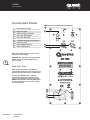
User
Manual
MODEL: QM 450A
Contents
Safety Precautions . . . . . . . . . . . . . . . . . . . . . . . . . . . . 1
General Description. . . . . . . . . . . . . . . . . . . . . . . . . . . . 3
Connection Panel . . . . . . . . . . . . . . . . . . . . . . . . . . . . . 4
System Connections. . . . . . . . . . . . . . . . . . . . . . . . . . . 5
Flying the QM450A . . . . . . . . . . . . . . . . . . . . . . . . . . . . 7
QM450A Specifications. . . . . . . . . . . . . . . . . . . . . . . . . 9
QM450A Reference Diagram. . . . . . . . . . . . . . . . . . . . . 10
User Manual
Q Motion Series
QM450A
QM450A
User Manual
Safety Precautions
• Be sure to read the instructions in this section carefully before use.
• Make sure you observe the instructions in this manual as the conventions of safety symbols and
messages are very important.
• We also recommend you keep this instruction manual handy for future reference.
Safety Symbol and Message Conventions
Safety symbols described below are used in this manual to prevent bodily injury and property
damage which could result from mishandling. Before operating your product, read this manual first
and understand the safety symbols and messages so you are thoroughly aware of any risks.
Flying and installation of this
speaker cabinet must be carried
out by suitably qualified personnel
following the locally authorised
and approved safety standards.
Do not attempt to clean the
painted enclosure with solvents
or petrochemical based cleaners.
Touching up scratched scan be
done with polyester paint.
Installation that allows direct
precipitation is not advised and
installation practise must prevent
liquids from entering the box.
Do not stack the speaker cabinet
in a manner that could cause
injury should a cabinet become
dislodged.
WARNING
Indicates a potentially hazardous
situation which, if mishandled, could
result in death or serious personal injury.
1
CAUTION
Before connecting or disconnecting
any connections including power,
make sure to set the master level
control to counter clockwise off. This
will prevent unexpected and possibly
damaging noises from the system.
Do not place sources of heat
on the speaker cabinet such as
lighting equipment or smoke
machines, and where possible
please keep out of direct
sunlight.
Q Motion Series
QM450A
User Manual
QM450A
User Manual
WARNING
When Installing the Unit
2
• Never plug in nor remove the power
supply plug with wet hands, as doing so
may cause electric shock.
• Do not place objects on the unit as they
can dislodge and cause personal injury
and/or property damage.
• When unplugging the power supply cord,
be sure to grasp the power supply plug;
never pull on the cord itself. Operating the
unit with a damaged power supply cord
may cause a fire or electric shock.
• Make sure that the volume control is set
to minimum position before power is
switched on. Loud noise produced at high
volume when power is switched on can
impair hearing.
• When moving the unit, be sure to remove
its power supply cord from the wall
outlet. Moving the unit with the power
cord connected to the outlet may cause
damage to the power cord, resulting in
fire or electric shock. When removing the
power cord, be sure to hold its plug to
pull.
• Do not operate the unit for an extended
period of time with the sound distorting.
This is an indication of a malfunction or
incorrect gain structure. Turn down the
sound source and check for the source of
distortion. Ignoring this can cause damage
to the speaker system and under some
circumstances can cause heat to generate
and result in a fire.
• Do not block the ventilation slots in the
unit’s cover. Doing so may cause heat to
build up inside the unit and result in fire.
• Avoid installing the unit in humid or dusty
locations, in locations exposed to direct
sunlight, near heaters, or in locations
generating sooty smoke or steam as doing
otherwise may result in fire or electric
shock.
User Manual
When the Unit is in Use
Q Motion Series
QM450A
• Contact your dealer as to cleaning
procedure. If dust is allowed to
accumulate inside the unit over a long
period of time, a fire or damage to the unit
may result.
• Switch off the power, and unplug the
power supply plug from the AC outlet
for safety purposes when cleaning or
leavingthe unit unused for many days.
QM450A
User Manual
General Description
The QM450a powered speaker is a two way
active bass reflex design suitable for mobile
and installation use.
Temporary installation is possible with the
Addition of a 35-36 mm speaker stand. Wall
mounting in the vertical and horizontal plane
is possible with WB350i wall mounting kit.
Installation
Hybridtec Amplifier Technology
The amplifier power is supplied by Quest
Engineering’s new “Hybridtec” digital class D
and analogue class A/B amplifier system. The
Hybridtec amplifier is controlled by an internal
analogue system controller. Simplified
Controls on the rear of the QM-450A make
operation easy. The QM-450A features an XLR
input, XLR link output, Gain control, 110Hz
High Pass/voice boost switch as well as
individually coloured Peak\Clip\Signal\Power
LED indicators providing clear and immediate
visual indicators.
The QM450A is a multi-purpose loudspeaker
equally at home as a front of house system
or as a powered foldback monitor. The
asymmetrical high frequency wave guide can
be rotated to a wide coverage in foldback
modes to give uniform close field coverage
without feedback inducing hot spots.
This type of hybrid design is to save weight,
lower potential heat output and also improve
sonic performance. A limiter monitors RMS
power for excessive input level.
Limiters and compressors are not a substitute
for sensible operation. The system will
sound its best when mixers and other signal
processors are not driven into distortion.The
design characteristics make the QM450A
suitable for both full range use or as the
Mid-High component of a multi way system
with bass enhancement. Coupled with a
Quest Engineering compact sub bass, the
QM450A can act as part of a compact array,
or stand alone point source multi way system
for full range sound at medium to high sound
pressure level.
Temporary installation is possible with the
35mm floor stand mounting in the base of
the enclosure. Fold-back installation can give
extra uniform stage performance by rotating
the horn flare to the “fold-back” position.
Three M8 threaded inserts are installed for
installation brackets. Two on the top and one
on the base of the QM450A enclosure.
Accessories
WB350i Wall bracket vertical or horizontal
mounting
Functional Design
The QM450A features an asymmetrical
horizontal angle along one side which makes
it suitable for use as a stage\foldback wedge
when laid flat.
3
Solid Build Construction
The QM450A is well suited to all professional
applications. The high grade lightweight ply
casing is specially formulated to withstand
demanding use and the heavy gauge
power-coated steel grill ensures the driver
and horn are always protected.
WARNING
Flying the box from one insert must not
be attempted! Improper installation may
result in damage, injury or death.
Q Motion Series
QM450A
User Manual
QM450A
User Manual
Connection Panel
1
Input Volume Control
2
High Pass Filter
3
Active and Clip Indicators
4
Line Level XLR Output
5
Line Level XLR Input
6
115V/230V Voltage Input Selector
7
Protection Fuse
8
Power ON/OFF Switch
9
Power Supply Input
1
2
3
110Hz
HIGH PASS
4
5
Make sure voltage selector is set for your
country’s correct voltage.
4
CAUTION: Use only same fuse replacement.
Please consult your Quest Engineering
service agent.
High Pass Filter
When in full range mode, the QM450A
internal filter settings are set to give a good
balance between voice and recorded music.
If using your QM450A with a sub bass
system, depressing the 110 Hz filter will
remove the low bass frequencies from the
QM450A and provide a mid-range EQ suited
to voice projection in the presence of high
powered sub bass.
6
7
8
9
User Manual
Q Motion Series
QM450A
QM450A
User Manual
System Connections
As a mono stand-alone system
If a powered sub bass is to be added to
the system, it is possible to switch the
110Hz high pass on to remove the low bass
frequencies from the QM450A. This will give a
“cleaner” vocal sound and make more power
available for voice reproduction.
As part of a multi way powered
system
If your powered sub bass system has an
electronic crossover output.
Connecting the QM450A through the output
of the sub bass crossover allows for the low
bass to be directed to the sub bass and the
upper bass/hi frequencies to be reproduced
by the QM450A. This approach takes the low
frequency load from the QM450A and makes
more power available for mid/high output.
INPUT
5
10
10
5
5
1
1
OUTPUT
1
2
INPUT
10
10
5
5
1
1
1
2
Q Motion Series
QM450A
User Manual
QM450A
User Manual
Speaker Placement as a Single Box
or in Arrays
The QM450A is intended for use as a single
speaker system or as part of a multiple
speaker setup with or without sub bass
reinforcement. It can also be installed in small
arrays of up to three boxes per array for very
wide coverage applications. When a group
of point source 90 degree speaker boxes
are placed together, it is possible to have
“interference effect” between some of the
boxes causing uneven frequency response.
This can be particularly noticeable in the
mid-high frequency area. If you intend to
set up the QM450A as part of a multiple box
array, see the section ‘Flying the QM450A’.
When positioning the speaker system on a
stage, make sure the HF horn at the top of
the speaker box is above the heads of the
audience. At full power the output of the
QM450A is very high and hearing damage can
result from short to medium term exposure.
For best results when the QM450A is used as
a front of house speaker, consider angling the
box forward slightly to direct the HF horn to
cover the audience area. The HF horn should
be aimed away from the ceiling and focused
on the intended area of coverage. This will
minimize HF reflections, lower the reverberant
field in the room and give better intelligibility.
6
Ideal QM450A Flown Configuration
User Manual
Q Motion Series
QM450A
QM450A
User Manual
Flying the QM450A
Before suspending any speaker system
always inspect all components (enclosure,
rigging frames, track fittings, etc.) for cracks,
deformations, corrosion, missing, loose or
damaged parts that could reduce strength
and safety of the array. Do not suspend the
speaker system until the correct preparation
of the installation site has been taken to avoid
health risks during and after the completion
of the installation. A licensed Professional
Engineer must approve the placement and
method of attachment to the structure prior to
the installation of any overhead object.
Rotating the Horn Flare
The asymmetrical horn flare can be rotated
through three separate planes of dispersion
depending on the speaker box requirement
and installation environment. The planes are
vertical installation, horizontal installation and
foldback monitor.
Good coverage of audiences often requires
wide dispersion at the base of the horn flare
to cover close listeners and a focused narrow
dispersion at the top of the flare to beam to
the back of the room.
WARNING
The QM450A horizontal horn covers both
“short-throw” and “long-throw” requirements
in a single system. For the majority of
installations (where the box is installed
vertically), the asymmetrical horn should be
used as supplied and will not need to be
rotated.
7
For horizontal installation rotate 45 degrees
so the arrow is pointing at the floor side so
as to have the “beaming” facility at the top of
the horn.
Foldback HF coverage
For stage foldback monitors the coverage
must be wide when performers are close
to the wedge and beam down the stage
to minimize the spill off the stage that may
interfere with the main PA.
For floor monitor use the horn must be
rotated with its “wide” dispersion (arrow
indicator), side directed towards the top of
the horizontal floor cabinet.
When removing and reinstalling the front
grill to rotate the horn, ensure the nuts are
not over tightened as this may make them
difficult to remove in future or cause them to
be damaged.
Ensure the box is securely located. If any doubt about the physical
stability, tie the box down with ratchet straps to a secure base.
Q Motion Series
QM450A
User Manual
QM450A
User Manual
QM450A Wave Guide Examples
45˚
+15˚
-45˚
60˚
QM450A FOH Configuration (front)
QM450A FOH Configuration (side)
-45
60˚
8
˚
+15
˚
45˚
QM450A Foldback Configuration (front)
QM450A Foldback Configuration (side)
45˚
+15˚
60˚
QM450A Horiztonal Configuration (front)
User Manual
Q Motion Series
QM450A
-45˚
QM450A Horizontal Configuration (front)
QM450A
User Manual
QM450A Specifications
Level (dB)
110
105
100
95
90
85
80
75
70
65
60
20
50
100
200
500
1k
2k
QM450A - Frequency Response - 1W, values scaled
5k
10k
20k
Frequency Response (Hz)
9
Technical Parameters
Power Amplifier Module Output
450 / 400+50 W RMS
Frequency Response
60 – 18 kHz (+/-3dB)
Maximum SPL output @ 1m
129.5dB @ 1kHz
Input Impedance
22kOhm balanced
Amplifier Protection
Limiter, Clip, short-circuit, on and off
Connections
1x XLR input
1x XLR output link
Controls
Power , Volume (Gain), 110Hz high-pass Mode
Indicators
Power, Signal, Clip, Peak square LEDs
Woofer Tweeter
12” high power mid-bass woofer
1” ferrite compression driver
Directivity
Asymmetric +15/-45 vertical
45/60 horizontal
Dimensions (HxDxW)
620 x 380 x 346.5 mm
Weight
20kg Net
* Quest Engineering reserves the right to make changes in specifications, or products without prior notice.
Q Motion Series
QM450A
User Manual
QM450A
User Manual
QM450A Reference Diagram
4
5
6
3bis
3
7
10
2
2bis
1
8
9
Item
Identification
Spare Part
1
QM450A wooden cabinet
QM350C
2
12” medium power woofer
T12001
2bis
Recone kit for 12” woofer
RT12001
3
1” exit ferrite compression driver
T1012
3bis
Replacement diaphragm for T1012
RT1012
4
Asymmetrical horn-flare
HWG350
5
Complete grill for QM350i/QM450A
HGQM350
6
Complete power module for QM450A
APM450A
7
Q-badge 25mm with spring loaded pin
HQB25
8
137mm rubber skids (x5)
HSK137
9
Pole mount plate
HPP350
Replaceable components of the power module
User Manual
Complete pre-amp PCB + LEDs + connectors
APRE450A
Amplifier Board module PCB with heat-sink
AAB450A
Connection plate for QM450A
HCP450A
Power switch complete block
EPS450A
Power voltage selector block
EVS450A
Volume knob
EVK450A
Q Motion Series
QM450A
QM450A
User Manual
11
Q Motion Series
QM450A
User Manual
Register Your Product
Thank you for choosing Quest. Please take the time
to complete your product registration card which is
included with the packaging.
Registering your Quest Engineering product will:
• CONFIRM YOUR WARRANTY
• REGISTER YOUR PRODUCT
• PROTECT YOUR NEW PRODUCT
REGISTER ONLINE:
www.questaudio.net/registration
www.questaudio.net