1
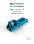
TECHNICAL MANUAL
CLINCHER®
HYDRAULIC ROTARY TABLES
Covers Rotary Table Models
HRT-20B & HRT-20C
4225 Highway 90, East
Broussard, Louisiana 70518
Phone: (337) 837-8847
Fax: (337) 837-8839
www.superior-manf.com
©Copyright, 2000, SUPERIOR Manufacturing & Hydraulics, Inc. All rights reserved. This document is
the property of SUPERIOR Manufacturing & Hydraulics, Inc. It is supplied as reference information to
users of our products. This document is considered confidential and is not to be disclosed, copied or
reproduced, transmitted, transcribed in any form or stored in any type of system without the express
written consent of SUPERIOR Manufacturing & Hydraulics, Inc.
CLINCHER®, LOCKJAW™ & GRIT FACE™ are trademarks of SUPERIOR Manufacturing &
Hydraulics, Inc.
The products described in this manual are covered by U.S. and foreign Patents and/or pending Patent
Applications.
This manual is not a controlled document and is
subject to revision without notice. To receive updates
and insure you have access to the latest information
concerning the CLINCHER® Rotary Tables HRT20B & HRT20-C, we request you complete this form and
return the lower half to SUPERIOR Manufacturing
and Hydraulics by mail or facsimile.
Name:
Company:
Address:
Address:
City:
Postal Code:
Telephone:
State:
Country:
Fax:
RT Model No.:
Assembly Date:
Serial No.:
CLINCHER® Rotary Tables HRT-20B & HRT-20C Technical
Manual
Registration Form
Name:
Return To:
Company:
Address:
Address:
City:
Postal Code:
Telephone:
RT Model No.:
Assembly Date:
State:
Country:
Fax:
Serial No.:
SUPERIOR Mfg. & Hyd.
4225 Hwy. 90 East
Broussard, LA 70518
USA
Telephone: 337-837-8847
Facsimile: 337-837-8839
Web Site: www.superior-manf.com
TABLE OF CONTENTS
Hazard Warnings
1
Description, Features, & Specifications
Certificate of Origin &Conformance
2
Operating Instructions
3
HRT20-B & HRT20-C Rotary Table Illustrations &
Bill of Materials
4
Motor Service Manuals
5
HRT-20B & HRT-20C CLINCHER® Rotary Tables
REVISION TABLE
Section
Page
Date
Description
CLINCHER® HYDRAULIC ROTARY TABLES
HRT-20B & HRT-20C
HAZARD WARNING
Nomenclature used in this manual:
WARNING
concerns an operating procedure or practice that, if not
strictly observed, can result in injury to personnel or loss of
life.
Caution
concerns an operating procedure or practice that, if not
strictly observed, can result in damage to or destruction of
equipment.
Note
concerns an operating procedure or practice that needs
highlighting.
CLINCHER® Rotary Tables are manufactured to provide a means to rotate drill pipe under
high torque conditions. They utilize high pressure hydraulic fluid power which can cause the
rotary table to move suddenly and with great force if the rotary table is not properly rigged up
and operated. CLINCHER® Rotary Tables contain rotating and reciprocating parts which can
severely or fatally injure personnel who are operating, repairing, or near this equipment during
its operation. WARNING: Rotary Tables are not to be operated by untrained personnel or
personnel with diminished physical or mental capacity. No work of any type, including
changing of dies, is to be carried out while the rotary table is connected to any hydraulic
power unit.
CLINCHER® Rotary Tables weigh 4100 lbs. WARNING: Users must insure the entire
suspension system including cables, rig mounting points, lift cylinders, tong lifting
brackets/bridles, winches, pulleys, counter weights, etc., are capable of handling the static
weight of the rotary table PLUS any shock loads which may be seen during operation.
WARNING: Users must provide a means of safely controlling the rotary table movements
in all directions when it is in use. Failure to account for its size, weight, movement and the
amount of torque developed could result in personnel injury or death.
CLINCHER® Rotary Tables utilize high pressure hydraulic fluids. Portions of the rotary table,
control valves, hydraulic lines may contain high pressure fluid even when the power unit is deenergized and the fluid supply hoses are disconnected. During normal operation the temperature
of the hydraulic fluids as well as hoses, piping, valves, etc., can rise to a level which can cause
burns.
SUPERIOR Manufacturing & Hydraulics, Inc.
CLINCHER® Hydraulic Rotary Tables
HRT-20B & HRT-20C
Revision: 11/00
Page 1 - 1
CLINCHER® HYDRAULIC ROTARY TABLES
HRT-20B & HRT-20C
HAZARD WARNING
WARNING: Personal protective gear including safety glasses, face shields, protective
gloves and protective clothing must be worn to guard against the hazards of high pressure
fluids. Tight fitting clothing is required to prevent entanglement in rotating components.
These tools should be serviced by thoroughly trained and qualified hydraulic technicians
using procedures to safely insure hydraulic pressure is bled from these circuits.
No attempt should be made to operate the CLINCHER® Rotary Table for any purpose other
than which it is intended. This system is capable of generating very large torsional loads which,
if improperly applied or controlled, could result in damage to the tubular, to the rotary table, or
could possibly result in injury or death of personnel.
Operators are cautioned to practice soft startups and stops to avoid unnecessary shock loads on
mechanical equipment and the hydraulic system. Extreme care must be taken when releasing
torsion stored within a string of pipe. The sudden release of hydraulic pressure will allow stored
torque to drive the rotary in the opposite direction in an extreme fashion.
SUPERIOR Manufacturing & Hydraulics, Inc.
CLINCHER® Hydraulic Rotary Tables
HRT-20B & HRT-20C
Revision: 11/00
Page 1 - 2
CROSS
GENERAL INFORMATION
HYDRAULIC PRODUCT
SAFETY
HYDRAULIC PRODUCT SAFETY
WARNING: Valve lever (spool) may "stick" (not center) under
certain conditions allowing the hydraulic equipment to continue to
operate and could cause serious injury, death or equipment failure.
VALVE SAFETY: Read and follow instructions carefully. Failure to observe instructions
and guidelines may cause serious injury, death or equipment failure. A sticking valve
(spool bind) may be caused by one or more of the following factors:
DIRTY OIL: Oil must be filtered to a minimum of 25 microns. Filters should be changed regularly spin-on types after 50 hours of initial use and then after every two hundred fifty hours of use. Use of
a condition indicator is recommended. Consult your tractor or implement owner’s manual for filtration and changing recommendations for internal systems.
OIL REQUIREMENTS: Premium quality anti-wear type oil with a viscosity between 100 and 200
SSU at operating temperatures. Certain synthetic oils may cause spool seals to swell and the valve
to stick. If in doubt, call CROSS Engineering.
IMPROPER HOOK UP OR MOUNTING: Always use the proper size fittings. Hook up "in" & "out"
as noted on the valve body. Do not overtorque pipe fittings. Mounting surfaces should be flat and
care should be used when tightening mounting bolts. Over-tightened bolts can cause spool bind
and casting breakage. When hooking a valve in series, always use a power beyond sleeve. Consult your tractor or implement manual to make sure you have the proper quick disconnect line
connected to the inlet of the remote valve.
MISAPPLICATION: Always use the proper valve for the job. CONVERTA, CD, CS or CA valves
should never be used for metered heavy load lifting - loaders or similar applications. Use an open
center valve for open center applications and a closed center valve for closed applications. If in
doubt, check with your tractor dealer. Contact CROSS if the valve allows the hydraulic equipment to
creep excessively.
MAINTENANCE: Make sure all bolts are tightened and torqued to the recommended specification.
Bent or broken parts should not be used. Replace immediately. Always use exact replacements.
Always protect valve spool from paint overspray.
Faulty quick disconnects can cause high back pressures and sticking spools. Check quick disconnects periodically to make sure they are functioning properly. If valve spool does not center or
appears to stick, do not use!
PUMPS & MOTORS SAFETY:
A relief or bypass in your hydraulic system is necessary to prevent pump from breakage due to
overpressurization. Use correct fittings and proper oil as noted in the technical service manual
packed with each unit. Change oil as recommended by your implement or tractor manufacturer.
CYLINDER SAFETY:
Check clevis clearances before, during and after extending the cylinder and before using the cylinder
under pressure to avoid possible injury, or bent or broken rods caused by binding. Never operate
a cylinder above recommended pressures. Never use a cylinder as a safety device when transporting equipment.
PINHOLE LEAKS:
If you observe a pinhole leak, discontinue use of the component. If oil has penetrated your skin or
contacted your eye, seek medical attention immediately!
DESCRIPTION, FEATURES, & SPECIFICATIONS
DESCRIPTION AND APPLICATION
The CLINCHER® Models HRT-20B & HRT-20C Hydraulic Rotary Tables are designed to add
high speed, high torque rotational capacity to snubbing units. This unit is mounted above the
snubbing unit’s hydraulic cylinders. A pneumatic or hydraulically actuated slip assembly
(supplied by others) can be bolted to the rotary’s top mounting flange to accommodate both pipe
pulling (tension) and pipe snubbing (compression) operations.
HRT-20C differs from HRT-20B in that it features a roller type thrust bearing instead of a thrust
bushing. This bearing provides enhanced performance in applications where pipe must be
“snubbed” into the well while rotating for extended periods of time. Such applications may
include shallow drilling, milling, window cutting, and side tracking.
FEATURES AND BENEFITS
The Rotary Table’s large bore design (11.06 inch minimum ID) will readily allow the passage of
large downhole tools. This feature significantly reduces tripping times when compared to other
systems which must be removed when large diameter tools such as mills, packers, or side pocket
mandrels are encountered.
Four single speed hydraulic motors with one piece shafts directly drive the Rotary Table to
provide high torque capacity in a compact package. High efficiency Rineer GA-15 vane type
motors are powered by the snubbing unit’s hydraulic power supply to eliminate the need for
additional power units. Precise speed, direction, and torque control are achieved by means of
pilot operated control valves (supplied separately). Note: A two speed motor option is available.
Motors are interconnected by welded supply and return manifolds with split flange o-ring
connections to provide optimum reliability in service.
Tensile loads (pulling pipe) are carried by a lubricated roller bearing. In the HRT-20B,
compressive loads (snubbing pipe) are transferred through a composite self lubricating thrust
bearing assembly. In the HRT-20C, compressive loads (snubbing pipe) are transferred through a
lubricated roller bearing. For extreme drilling applications, long term heavy compressive loads
will be encountered with simultaneous high speed rotation. Lubricated bronze bushings absorb
any radial loads resulting from eccentric slip assembly loading. The enclosed gear train and
bearings are lubricated and cooled by hydraulic fluid used to drive the motors.
A high pressure hydraulic swivel system is incorporated within the rotary to allow remote control
of the slips without the need for disconnecting or reconnecting hydraulic hoses. The swivel
contains a fresh water heat exchanger to avoid heat buildup and potential seal damage during
periods of extended rotation.
SUPERIOR Manufacturing & Hydraulics, Inc.
CLINCHER® Hydraulic Rotary Tables
HRT-20B & HRT-20C
Revision: 11/00
Page 2 - 1
DESCRIPTION, FEATURES, & SPECIFICATIONS
SPECIFICATIONS
Minimum Internal Diameter
11.06 inches
Maximum External Diameter of Mounting Flange
34.00 inches
Maximum Manifold Diameter
35.70 inches
Overall Height / HRT-20B
HRT-20C
39.00 inches
42.75 inches
Approximate Weight / HRT-20B
HRT-20C
3,500 pounds
4,100 pounds
Maximum Tensile Capacity
460,000 pounds
Maximum Compressive Capacity
170,000 pounds
HYDRAULIC MOTOR SPECIFICATIONS
Number of Motors
4
Manufacturer / Model
Rineer GA-15
Displacement (per/motor)
15 in3 / Revolution
Maximum Torque (per/motor) @ 3000 psi
560 ft.lbs.
Maximum Continuous Motor Speed
1500 rpm
Maximum Intermittent Motor Speed 1
2000 rpm
Maximum Continuous Motor Pressure
Maximum Intermittent Motor Pressure
1
3000 psi
1
3500 psi
Intermittent condition 10% of every minute.
Rotary Table Gear Reduction
9.923:1
Continuous Torque Rating @ 2,500 psi
18,000 ft.lbs.
Maximum Torque Developed (@ 3,000 psi)
22,000 ft.lbs.
Pressure Required to Develop 15,000 ft.lbs.
2,032 psi
SUPERIOR Manufacturing & Hydraulics, Inc.
CLINCHER® Hydraulic Rotary Tables
HRT-20B & HRT-20C
Revision: 11/00
Page 2 - 2
DESCRIPTION, FEATURES, & SPECIFICATIONS
SPECIFICATIONS
Rotational Speed @ 120 gpm
47 rpm
Rotational Speed @ 155 gpm
60 rpm
Maximum Recommended Flow Rate
200 gpm
Supply & Return Manifold Connections
2" NPT (Sch 160)
Maximum Allowable Flow Rate 2
392 gpm
Maximum Allowable Rotational Speed 2
152 rpm
2
Manifold modifications are required for flow rates above 209 gpm.
Maximum Swivel Hydraulic Pressure
1,500 psi
Swivel Hydraulic Connections
3/8" NPT
Top Plate Connections to Slips
3/8" NPT
Maximum Swivel Coolant Pressure
60 psi
Recommended Fresh Water Coolant Flow Rate
5-10 gpm
Swivel Coolant Connections
3/8" NPT
GENERAL INFORMATION
The HRT-20B and HRT-20C Hydraulic Rotary Tables feature an increased tensile load rating
from 340,000 to 460,000 pounds when compared to earlier units. This upgrade is achieved by
eliminating the small slip assembly mounting bolt hole pattern and increasing the thickness of
the top mounting flange (ref Item 1) from 2" to 4". This unit features face seal o-rings between
hub (ref Item 9) and the top mounting flange. Ports for slip system control hydraulics are
integral to the top mounting flange to eliminate potential leak points.
SUPERIOR Manufacturing & Hydraulics, Inc.
CLINCHER® Hydraulic Rotary Tables
HRT-20B & HRT-20C
Revision: 11/00
Page 2 - 3
Snub Capacity Calculations
Hydraulic Horsepower (HHP) reqd f/ speed at 18,000 ft lbs
350
300
250
200
150
100
50
0
0
2
4
6
8
10
12
14
16
17
19
21
23
25
27
29
31
33
35
37
39
41
43
45
47
48
50
52
54
56
58
60
62
64
66
68
70
72
74
76
78
Hydraulic Horsepower (HHP) reqd f/ speed at 18,000 ft lbs
HRT-20B & HRT-20C Hydraulically Driven Rotary Table
rotary speed (RPM)
HHP = Pressure (psi) x flowrate (gpm) / 1714
Technical Manual HRT-20B & HRT-20C Rev. 11/00
Page 2 - 4
Hrt20b.123
Snub Capacity Calculations
HRT-20B & HRT-20C Hydraulically Driven Rotary Table
rotary speed (RPM)
90
rotary speed (RPM)
80
70
60
50
40
30
20
10
0
5
10
15
20
25
30
35
40
45
50
55
60
65
70
75
80
85
90
95
100
105
110
115
120
125
130
135
140
145
150
155
160
165
170
175
180
185
190
195
200
0
inlet flowrate (GPM)
Technical Manual HRT-20B & HRT-20C Rev. 11/00
Page 2 - 5
Hrt20b.123
Snub Capacity Calculations
HRT-20B & HRT-20C Hydraulically Driven Rotary Table
rotary torque (ft lbs)
rotary torque (ft lbs)
30000
25000
20000
15000
10000
5000
0
100
200
300
400
500
600
700
800
900
1000
1100
1200
1300
1400
1500
1600
1700
1800
1900
2000
2100
2200
2300
2400
2500
2600
2700
2800
2900
3000
3100
3200
3300
3400
3500
0
inlet pressure (PSI)
Technical Manual HRT-20B & HRT-20C Rev. 11/00
Page 2 - 6
Hrt20b.123
DESCRIPTION, FEATURES, & SPECIFICATIONS
Photo 1
SUPERIOR MANUFACTURING & HYDRAULICS
Hydraulically Driven Rotary Table
SUPERIOR Manufacturing & Hydraulics, Inc.
CLINCHER® Hydraulic Rotary Tables
HRT-20B & HRT-20C
Revision: 11/00
Page 2 - 7
OPERATING INSTRUCTIONS
User should be advised the continuous operating conditions should not exceed the continuous
torque rating of 18,000 foot pounds or maximum recommended flow rate of 200 gpm. Maximum
tensile or compressive ratings must not be exceeded. The Rotary Table should be removed from
the snubbing unit if extended jarring operations are expected. Do not operate this equipment
outside of these ratings. Failure to comply with these limits could result in premature equipment
failure, and expose personnel to potential injury or death.
Note: This unit uses a small amount of hydraulic oil which bypasses from the motors during
operation to cool and lubricate the gears and bearings. Note: In early manufactured Rotary
Tables these motors were not equipped with motor seals. Do not install seals during repair or
maintenance operations. Note: Later manufactured Rotary Tables are equipped with motor seals.
In these units, case drains must be connected to each motor to allow motor case pressure to be
bled off directly to the hydraulic reservoir by means of an independent drain hose.
After rigging up the Rotary Table on the snubbing unit and before beginning rotation, the users
must insure the case is filled with clean hydraulic oil. Note: Approximately 6 gallons of oil are
required to fully fill case. The HRT-20C Rotary Table uses approximately 7 1/2 gallons of SAE
90 weight gear oil in the case to lubricate and cool the bearings and gear train. Now our units do
not require a gear case return hose. Fill using the following procedures shown below:
All Rotary Tables have 3/4" NPT ports located on the flange of the upper housing. On the latest
units, one port is stamped “RETURN” and is equipped with a dip tube (ref Item 38) to enhance
oil circulation. The port 180 degrees from the case drain “RETURN” port is stamped “VENT”.
Fill the case by removing the plugs in the “RETURN” and “VENT” ports. Use an elongated
funnel to direct hydraulic oil into the case through the “RETURN” port unit until oil is visible in
Earlier units also have 3/4" NPT ports located on the flange of the upper housing but these ports
are not stamped “RETURN” and “VENT”. These units may be filled from either port. In these
earlier units, the upper sight glass (ref Item 50) must be removed to allow air to escape from the
case during filling operations. Use an elongated funnel to direct hydraulic oil into the case unit
until oil is visible in upper sight glass port. Reinstall sight glass in upper port.
A case drain line must be run from the hydraulic power unit’s reservoir to the 3/4" NPT ports
(ref Detail A, Assembly Dwg’s) in the upper housing. On newer units connect this line to the port
labeled “RETURN”. The line may be connected to either port on earlier units which are not
labeled. The case drain line must loop over the manifolds to insure the case remains full of fluid
during operation. It is vital that the case drain line be free of restrictions and back pressure.
Otherwise excessive case pressure may cause seal leaks, excess heat buildup, or extreme
conditions, actual failure of the housing due to excessive internal pressure.
SUPERIOR Manufacturing & Hydraulics, Inc.
CLINCHER® Hydraulic Rotary Tables
HRT-20B & HRT-20C
Revision: 11/00
Page 3 - 1
OPERATING INSTRUCTIONS
Use a high pressure grease gun with extended nozzle to inject Texaco Marfax grease or
equivalent into the two grease zerts (ref Item 7) located in the upper housing. Inject grease until
grease escapes between hub (ref Item 9) and upper seal retainer (ref Item 5). After initial
injection of grease, we recommend these ports be re-lubricated after every four (4) hours of
rotation.
Connect hydraulic swivel coolant connections to a regulated supply of fresh water. When
temperatures are 32° F or less, water in rotary swivel should be replaced with coolant (Anti-Freeze).
Use Teflon based thread compound to seal connections, care must be taken to avoid over
tightening or damaging the 3/8" NPT connections in the aluminum swivel housing. Use of
brackish or salt water may result in corrosion of the swivel. Note the inlet pressure should not
exceed 60 psi. Users may have to install a pressure regulator to avoid over pressuring the swivel.
A filter may also be required to insure heat exchanger does not become clogged with foreign
debris. Coolant exhaust or return line back pressure should not exceed 5 psi.
Connect hydraulic swivel slip control lines to slip control valve. Use Teflon based thread
compound to seal connections, care must be taken to avoid over tightening or damaging the 3/8"
NPT connections in the aluminum swivel housing. Maximum hydraulic pressure to operate slips
should not exceed 1,500 psi. All pressure must be drained from the swivel and slip control
circuit before rotating. Failure to abide by this guideline will result in excessive heat buildup,
wear of hub surface, and premature seal failure. Superior recommends the slip circuit be
controlled by means of a directional control valve with float center (connected to tank line). A
pilot operated check valve or counter balance valve may be incorporated within the slip assembly
if the user desires to trap pressure within the slip=s cylinders while rotating. Note: If hydraulic
system has high back pressure in the return circuit, a separate return line may be desirable to
maximize seal life.
A rotational locking pin assembly (ref Item’s 32, 33, 34, & 35) is provided to lock the hub and
top mounting flange when installing the slip assembly or when tripping pipe. It is not designed
to prevent rotation caused by pressurizing the hydraulic motors. Applying high pressure to the
motors when the locking pin assembly is engaged may cause equipment damage or could result
in sudden unexpected movement.
Operators are cautioned to practice soft startups and stops to avoid unnecessary shock loads on
mechanical equipment and the hydraulic system. Extreme care must be taken when releasing
torsion stored within a string of pipe. The sudden release of hydraulic pressure will allow stored
torque to drive the rotary in the opposite direction in an extreme fashion.
SUPERIOR Manufacturing & Hydraulics, Inc.
CLINCHER® Hydraulic Rotary Tables
HRT-20B & HRT-20C
Revision: 11/00
Page 3 - 2
3.75
3.75
3.75
7.25
HRT-20B / 39.00
HRT-20C / 42.75
4.000
10.75 C-C
1
317
Approx. Weight w/ Manifolds
3,500 lbs.
3
2
3/8 NPT
(4) PLCS.
ON SWIVEL
NOTE 1: LOWER HOUSING WELDMENT / P/N: RT1001
INCLUDES:
RT1001-S1 / BOTTOM BEARING HOUSING
RT1001-S3 / TOP MOUNTING PLATE
RT1001-S5 / BEARING RETAINER
RT1001-S6 / BOTTOM MOUNTING FLANGE
24
25
Apply Never Seeze
37 21 24 ft.lbs. Max. Torque
4 21 Apply Removable Loctite
8
5
Apply Removable Loctite
27 ft.lbs. Max. Torque 42
36 ft.lbs. Max. Torque
22
40
41
41
DETAIL A
1
INSTALLATION DETAIL OF ITEM #3
3/8 NPT
(2) PLCS.
3/8 NPT
SEE DETAIL A
32
3/8 NPT
(4) PLCS.
ON SWIVEL
56
12
33
44 Apply Removable Loctite
6
27
9
3
34
10
11
7
30 31
SEE SHEET
6 OF 6 13
Apply Never
Seeze 412 ft.lbs.
Max. Torque
46
23
43
14
Apply Removable
Loctite 180 ft.lbs. 15
Max. Torque
38
LOCATE ON
RETURN PORT
12
17
11 12
35
INSTALLATION DETAIL OF ITEM #11 & #12
9
18
17
18
16
14
5
8
12 11
19
20
3
See Note 1
22
8
1.250
19
45
See Note 1
44 Apply Removable Loctite
8
36
Apply Removable
42 21 Loctite 36 ft.lbs.
Max. Torque
SECTION VIEW SHOWN OUT OF PHASE
(SHOWN W/O MOTORS MANIFOLD ASSY.)
FOR CLARITY PURPOSE
HRT-20B HYDRAULIC ROTARY TABLE
RT1000 SHT 3 OF 6
SECTION A-A
36
INSTALLATION DETAIL OF ITEM #8
4225 HWY. 90 EAST
BROUSSARD, LA 70518
(318) 837-8847
THIS DOCUMENT IS THE PROPERTY OF SUPERIOR MANUFACTURING &
HYDRAULICS AND IS CONSIDERED CONFIDENTIAL. THIS INFORMATION
MAY NOT BE USED, DISCLOSED, COPIED, OR REPRODUCED IN ANY
FORM, WITHOUT THE EXPRESS WRITTEN CONSENT OF SUPERIOR
MANUFACTURING & HYDRAULICS.
REV. #
LOG #
11/14/00
DATE
REF: S:\Equip Manuals\Dwgs\
Rotary Tbls\RT1000 sh3 of 6.wpg
Approx. Weight w/ Manifolds
4,100 lbs.
3
NOTE 1: GEAR HOUSING WELDMENT / P/N: RT1050
INCLUDES:
RT1001-S1 / BOTTOM BEARING HOUSING
RT1001-S6 / BOTTOM MOUNTING FLANGE
RT1001-S7 / GEAR CASE RING
RT1001-S8 / BEARING RETAINER
2
3/8 NPT
(4) PLCS.
ON SWIVEL
24
25
Apply Never Seeze
37 21 24 ft.lbs. Max. Torque
4 21 Apply Removable Loctite
8
36 ft.lbs. Max. Torque
5
Apply Removable Loctite
27 ft.lbs. Max. Torque 42
22
40
41
41
DETAIL A
1
INSTALLATION DETAIL OF ITEM #3
3/8 NPT
(2) PLCS.
3/8 NPT
SEE DETAIL A
32
3/8 NPT
(4) PLCS.
ON SWIVEL
56
12
33
44 Apply Removable Loctite
9
6
3
34
10
35
11
27
7
12
17
11 12
30 31
Apply Never
Seeze 412 ft.lbs.
Max. Torque
23
16
46
LOCATE ON
RETURN PORT
14
Apply Removable
Loctite 180 ft.lbs.
15
Max. Torque
17
See Note 1
12 11
3
14
20 19
8
8
8
See Note 1
44 Apply Removable Loctite
22
5
18
16
19
18
43
13
38
INSTALLATION DETAIL OF ITEM #11 & #12
9
SECTION A-A
36
36
Apply Removable
42 21 Loctite 36 ft.lbs.
INSTALLATION DETAIL OF ITEM #8
Max. Torque
SECTION VIEW SHOWN OUT OF PHASE
(SHOWN W/O MOTORS MANIFOLD ASSY.)
FOR CLARITY PURPOSE
HRT-20C HYDRAULIC ROTARY TABLE
4225 HWY. 90 EAST
BROUSSARD, LA 70518
(318) 837-8847
THIS DOCUMENT IS THE PROPERTY OF SUPERIOR MANUFACTURING &
HYDRAULICS AND IS CONSIDERED CONFIDENTIAL. THIS INFORMATION
MAY NOT BE USED, DISCLOSED, COPIED, OR REPRODUCED IN ANY
FORM, WITHOUT THE EXPRESS WRITTEN CONSENT OF SUPERIOR
MANUFACTURING & HYDRAULICS.
REV. #
LOG #
11/14/00
DATE
REF: S:\Equip Manuals\Dwgs\
Rotary Tbls\HRT20-C Assy.wpg
o 35.75 O.D.
51
UPPER MANIFOLD WELDMENT
P/N: RT1030
52
LOWER MANIFOLD WELDMENT
P/N: RT1031
SEE NOTE 1
2" NPT
53
7/16"-14 x 2 1/2" SHCS
P/N: 1229
Apply Never Seeze
52 ft.lbs. Max. Torque
(4) PER FLANGE
54
2-222 O-RING
P/N: 2-222
(1) PER FLANGE
LOWER
MANIFOLD
NOTE 1: FOR PRODUCTIONS AFTER 11/00
1/2" THREAD-O-LET ADDED TO
MANIFOLD WELDMENTS.
55
7/16" HI-COLLAR LOCKWASHER
P/N: 1082
(4) PER FLANGE
HRT-20B & HRT-20C
HYDRAULIC ROTARY TABLE
RT1000 SHT 4 OF 6
UPPER
MANIFOLD
MOTOR
SIDE VIEW
4225 HWY. 90 EAST
BROUSSARD, LA 70518
(318) 837-8847
THIS DOCUMENT IS THE PROPERTY OF SUPERIOR MANUFACTURING &
HYDRAULICS AND IS CONSIDERED CONFIDENTIAL. THIS INFORMATION
MAY NOT BE USED, DISCLOSED, COPIED, OR REPRODUCED IN ANY
FORM, WITHOUT THE EXPRESS WRITTEN CONSENT OF SUPERIOR
MANUFACTURING & HYDRAULICS.
REV. #
LOG #
11/14/00
DATE
REF: S:\Equip Manuals\Dwgs\
Rotary Tbls\RT1000 sh4 of 6.wpg
A
.631 OVERALL THICKNESS
INSTALL THIS
SIDE UP
GARLOCK PADS
P/N: RT1012
(8) PLCS. 3
#4-40 x 3/8 FHSCS
P/N: RT1014
(48) PLCS.
USE REMOVABLE LOCTITE
TOP THRUST BUSHING PLATE
P/N: RT1005
DETAILS
A
SECTION A - A
HRT-20B HYDRAULIC ROTARY TABLE
RT1000 SHT 6 OF 6
TOP VIEW
3
DSB 10-11-99
2
NM
11-02-98
Show pads on top side only.
1
SAL
96-10-007
Change matl. from bronze to aluminum.
REV.# BY
TOP THRUST BUSHING ASSEMBLY
FOR HRT-20B ONLY
ASSEMBLY NO. RT1007
LOG #
Change Qty. of Garlock pads fm 16 to 8, one side only.
DESCRIPTION OF REVISION
4225 HWY. 90 EAST
BROUSSARD, LA 70518
(318) 837-8847
THIS DOCUMENT IS THE PROPERTY OF SUPERIOR MANUFACTURING &
HYDRAULICS AND IS CONSIDERED CONFIDENTIAL. THIS INFORMATION
MAY NOT BE USED, DISCLOSED, COPIED, OR REPRODUCED IN ANY
FORM, WITHOUT THE EXPRESS WRITTEN CONSENT OF SUPERIOR
MANUFACTURING & HYDRAULICS.
DATE: 10/02/00
BY: DT
REF: S:\Equip Manuals\Dwgs\
Rotary Tbls\RT1000 sh6 of 6.wpg
POLYPACK
P/N: 12501437
MOTOR SHAFT
O-RING
P/N: 2-150
SEAL RETAINER
P/N: 55088
SNAP RING
P/N: 0150111
MOTOR SHAFT BEARING
P/N: 0150710
SNAP RING
P/N: 1945
W/ OUT WIPER RING
4225 HWY. 90 EAST
BROUSSARD, LA 70518
(318) 837-8847
MOTOR ASSEMBLY
FOR CLARITY PURPOSE ONLY
NOT TO SCALE
THIS DOCUMENT IS THE PROPERTY OF SUPERIOR MANUFACTURING &
HYDRAULICS AND IS CONSIDERED CONFIDENTIAL. THIS INFORMATION
MAY NOT BE USED, DISCLOSED, COPIED, OR REPRODUCED IN ANY
FORM, WITHOUT THE EXPRESS WRITTEN CONSENT OF SUPERIOR
MANUFACTURING & HYDRAULICS.
Page 4 - 7
1
REV. #
LOG #
09/03/02
DATE
REF: P:\Manuals\Equip Manuals\Dwgs\
Motor\Motor CLE5500+ sht2 rev1.wpg
HRT-20B HYDRAULIC ROTARY TABLE
BILL OF MATERIALS
Item Qty.
No. Reqd
Part No.
Item Qty.
No. Reqd
Description
Part No.
Description
1
1
RT1020
Top Mounting Flange
31
12
1224
Lockwasher - 7/8"
2
1
RT1002-A
Rotary Swivel
32
1
RT1018
Locking Pin
3
5
CLEBU9656 Rotary Seal
33
1
RT1013
Locking Pin Handle
4
12
1049
HHCS - 3/8"-16 x 1 1/2"
34
1
RT1035
Hitch Pin
5
1
RT1004
Upper Seal Retainer
35
1
RT1024
Compression Spring
6
1
RT1011
Upper Housing
36
1
RT1040
Lower Seal Retainer
7
2
1001
Grease Zert - 1/8"
37
6
1047
HHCS - 3/8"-16 x 1"
8
2
1400239
Oil Seal
38
1
RT1041
Dip Tube
9
1
RT1003
Main Hub
39
1
1609
Flush Plug - 3/8" NPT
10
1
RT1006
Top Bushing
40
3
RT1021
Swivel Spacers
11
2
2-459
O Ring 15"ID 15 1/2"OD 1/4"W
41
2
2-208
O Ring 5/8"ID 7/8"OD 1/8"W
12
2
8-459
Backup Ring
42
15
238
SHCS - 3/8"-16 x 1 1/2"
13
1
RT1007
Top Thrust Bushing Assy.
43
1
2-461
O Ring 16"ID 16 1/2"OD 1/4"W
14
1
RT1008
Ring Gear
44
6
1238
Set Screw - 1/2"-13 x 1 1/4"
15
10
259
SHCS - 5/8"-11 x 2 1/2"
45
4
RT1026
Motor Bearing Shims
16
1
140TP158
Thrust Bearing
46
2
58063
Set Screw - 5/8"-11 x 1 1/4"
17
4
RT1009-A
Motor Shaft
47
10
1239
SHCS - 3/4"-10 x 4 1/2"
18
4
1899
Bearing, 308 SZZ
48
---
----------
----------
19
1
RT1001
Lower Housing Weldment
49
1
1610
Flush Plug - 3/4" NPT
20
1
RT1010
Bottom Bushing
50
2
1499-A
Sight Glass Plug - 3/4"-10 NPT
21
30
134
Lockwasher - 3/8"
51
1
RT1030
Upper Manifold Weldment
22
2
RT1015
Seal Retainer Gasket
52
1
RT1031
Lower Manifold Weldment
23
1
RT1023
O Ring 27.1875 OD 3/16 T
53
32
1229
SHCS - 7/16"-14 x 2 1/2"
24
1
RT1017
Swivel Retainer Ring Assy.
54
8
2-222
O Ring 1 1/2"ID 1 3/4"OD 1/8"W
25
1
CLEBU9655 External Snap Ring
55
32
1082
Lockwasher - 7/16" Hi Collar
26
4
RT1022
Rineer Hyd. Motor GA15
56
1
RT1019
Locking Pin Housing
27
4
RT1016
Motor Gasket
57
1
55088
Seal Retainer
28
16
1106-A
SHCS - 1/2"-13 x 1 1/2"
29
16
1103
Lockwasher - 1/2"
30
12
1237
SHCS - 7/8"-9 x 3 1/4"
SUPERIOR Manufacturing & Hydraulics, Inc.
CLINCHER® Hydraulic Rotary Tables
HRT-20B & HRT-20C
Revision: 9/09
Page 4 - 8
HRT-20C HYDRAULIC ROTARY TABLE
BILL OF MATERIALS
Item Qty.
No. Reqd
Part No.
Description
Item Qty.
No. Reqd
Part No.
Description
1
1
RT1020
Top Mounting Flange
31
12
1224
Lockwasher - 7/8"
2
1
RT1002-A
Rotary Swivel
32
1
RT1018
Locking Pin
3
5
CLEBU9656 Rotary Seal
33
1
RT1013
Locking Pin Handle
4
12
1049
HHCS - 3/8"-16 x 1 1/2"
34
1
RT1035
Hitch Pin
5
1
RT1004
Upper Seal Retainer
35
1
RT1024
Compression Spring
6
1
RT1011
Upper Housing
36
1
RT1040
Lower Seal Retainer
7
2
1001
Grease Zert - 1/8"
37
6
1047
HHCS - 3/8"-16 x 1"
8
2
1400239
Oil Seal
38
1
RT1055
Dip Tube
9
1
RT1051
Main Hub
39
1
1609
Flush Plug - 3/8" NPT
10
1
RT1006
Top Bushing
40
3
RT1021
Swivel Spacers
11
2
2-459
O Ring 15"ID 15 1/2"OD 1/4"W
41
2
2-208
O Ring 5/8"ID 7/8"OD 1/8"W
12
2
8-459
Backup Ring
42
15
238
SHCS - 3/8"-16 x 1 1/2"
13
1
RT1052
Spacer
43
1
2-461
O Ring 16"ID 16 1/2"OD 1/4"W
14
1
RT1008
Ring Gear
44
6
1238
Set Screw - 1/2"-13 x 1 1/4"
15
10
259
SHCS - 5/8"-11 x 2 1/2"
45
---
----------
----------
16
2
140TP158
Thrust Bearing
46
2
58063
Set Screw - 5/8"-11 x 1 1/4"
17
4
RT1053
Motor Shaft
47
10
1239
SHCS - 3/4"-10 x 4 1/2"
18
4
1899
Bearing, 308 SZZ
48
---
----------
----------
19
1
RT1050
Lower Housing Weldment
49
1
1610
Flush Plug - 3/4" NPT
20
1
RT1010
Bottom Bushing
50
2
1499-A
Sight Glass Plug - 3/4"-10 NPT
21
30
134
Lockwasher - 3/8"
51
1
RT1030
Upper Manifold Weldment
22
2
RT1015
Seal Retainer Gasket
52
1
RT1031
Lower Manifold Weldment
23
1
RT1023
O Ring 27.1875 OD 3/16 T
53
32
1229
SHCS - 7/16"-14 x 2 1/2"
24
1
RT1017
Swivel Retainer Ring Assy.
54
8
2-222
O Ring 1 1/2"ID 1 3/4"OD 1/8"W
25
1
CLEBU9655 External Snap Ring
55
32
1082
Lockwasher - 7/16" Hi Collar
26
4
RT1022
Rineer Hyd. Motor GA15
56
1
RT1019
Locking Pin Housing
27
4
RT1016
Motor Gasket
57
1
55088
Seal Retainer
28
16
1106-A
SHCS - 1/2"-13 x 1 1/2"
29
16
1103
Lockwasher - 1/2"
30
12
1237
SHCS - 7/8"-9 x 3 1/4"
SUPERIOR Manufacturing & Hydraulics, Inc.
CLINCHER® Hydraulic Rotary Tables
HRT-20B & HRT-20C
Revision: 9/09
Page 4 - 9
SECTION 5
MOTOR SERVICE MANUALS
To request copy of Rineer Motor
Service Manuals, please contact:
Superior Manufacturing & Hydraulics
4225 Hwy. 90 East
Broussard, LA 70518
Phone: 337-837-8847
Fax: 337-837-8839
www.superior-manf.com
SUPERIOR Manufacturing & Hydraulics, Inc.
CLINCHER® Hydraulic Rotary Tables
HRT-20B & HRT-20C
Revision: 11/00
Page 5 - 1