1
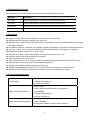
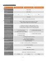
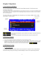
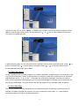
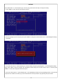
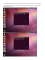
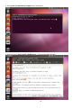
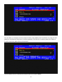
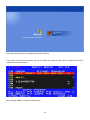
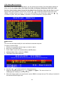
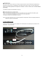
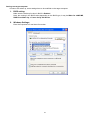
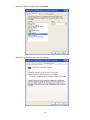
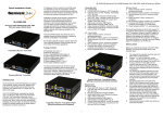
8 Port / 16 Port / 32 Port 1RU Rack Mount CAT 5 KVM Switch – VGA, USB & PS/2 Optional Remote IP Access Optional Remote CAT 5 Access User Manual Version 2.0.1 29-03-2013 Contents CHAPTER 1 INTRODUCTION .....................................................................................................................................3 1.1 PACKAGE CONTENTS......................................................................................................................................... 3 1.2 FRONT PANEL VIEW........................................................................................................................................... 4 1.3 REAR PANEL VIEW ............................................................................................................................................ 4 1.4 OPTIONAL ACCESSORIES ................................................................................................................................... 5 1.5 FEATURES ........................................................................................................................................................ 5 1.6 SYSTEM REQUIREMENTS ................................................................................................................................... 5 1.7 TECHNICAL SPECIFICATIONS .............................................................................................................................. 6 CHAPTER 2 HARDWARE INSTALLATION ................................................................................................................7 2.1 INSTALL CAT 5 KVM DONGLES .......................................................................................................................... 7 2.2 INSTALL CAT 5 KVM SWITCH ............................................................................................................................ 7 2.3 DDC-2 PROTOCOL SUPPORT ............................................................................................................................ 7 2.4 HOT PLUGGING ................................................................................................................................................. 7 CHAPTER 3 OPERATION ...........................................................................................................................................8 3.1 PORT SELECTION BY OSD MENU ....................................................................................................................... 8 3.2 SELECTING A COMPUTER ................................................................................................................................... 8 3.3 OSD HOTKEY FUNCTIONS ................................................................................................................................. 8 F1: Auto (Auto Scan) .....................................................................................................................................8 F2: Name (Port Name) ..................................................................................................................................9 F3: Secu (Security) ........................................................................................................................................9 F5: Manu (Manual Scan) .............................................................................................................................10 F6: (Check Mark) .....................................................................................................................................10 F7: ACPI (Green Command) ....................................................................................................................... 11 F8: Sched (Scheduling) ...............................................................................................................................23 CTRL: More (More Functions).....................................................................................................................25 3.4 CAT 5 KVM CASCADE .................................................................................................................................... 27 CHAPTER 4 KVM OVER IP MODULE (OPTIONAL) ................................................................................................30 4.1 KVM OVER IP MODULE INSTALLATION .............................................................................................................. 30 4.2 REMOTE WAKEUP ........................................................................................................................................... 30 CHAPTER 5 CAT5 KVM CONSOLE EXTENDER MODULE (OPTIONAL) ..............................................................33 5.1 CAT 5 CONSOLE EXTENSION UNIT INSTALLATION.............................................................................................. 33 5.2 SHARED CONSOLE OPERATION ........................................................................................................................ 33 CHAPTER 6 CERTIFICATIONS ................................................................................................................................34 2 Chapter 1 Introduction 1.1 Package Contents Included 1 x ServerLink CAT 5 KVM Switch 1 x Rack Mount Kit 1 x AC Power Cable 1 x Set of Footpads 1 x CD-ROM with User Manuals, Quick Installation Guides and Utilities Optional KVM over IP Module 150m CAT 5 KVM Console Extension Unit Please make sure all included components are present and in good order. If anything is missing, or was damaged in shipping, please contact your local dealer. Please read this manual thoroughly and follow the installation and operation procedures carefully to prevent any damage to the switch or to any other devices. Brief Introduction The ServerLink 8 port, 16 port or 32 port CAT 5 KVM Switches can control attached servers or computers from a local or remote console. They are loaded with features such as one local console port, plus an additional optional CAT 5 based remote console port or one additional optional IP based remote console port, On-Screen-Display (OSD) menu, password security, hot-key control, push button port selection and auto scan control. They have complete keyboard and mouse emulation for simultaneous and flawless server boot-up process. Designed with intelligent video Gain/EQ (equalizer) adjustments to tweak the video image individually for each server so that each server can be up to 40 metres away from the console drawer. With the optional CAT 5 based remote console port you can remotely control servers and computers. You can locate a second console (monitor, keyboard and mouse) up to 150 metres away from the KVM switch. The built-in CAT 5 transmitter synthesizes VGA monitor and keyboard/mouse signals and transmits these signals to the remote CAT 5 receiver over standard CAT 5 or CAT 6 cable. With the optional IP based remote console port you can control connected servers locally at the rack or remotely via the Internet using a standard browser. You can securely gain BIOS level access to systems for maintenance, support or failure recovery over the Internet. Communication is secure via SSL encryption. 3 1.2 Front Panel View Description Port LED colour If the Port LED is lit RED this indicates the console port is linked to this computer port RED If the Port LED is lit GREEN this indicates the computer is connected and powered on GREEN Shift LED colour Description (32 port only) RED GREEN If the Shift LED is lit RED this indicates the Port LED is showing the status of ports 1-16 If the Shift LED is lit GREEN this indicates the Port LED is showing the status of ports 17-32 1.3 Rear Panel View No. Component Description 1 Computer Ports (8 / 16 / 32) Connect to Computers via KVM CAT 5 Dongle 2 PS/2 Mouse port x 1 A local console PS/2 Mouse can connect here 3 PS/2 Keyboard port x 1 A local console PS/2 Keyboard can connect here 4 CAT 5 Extension Port Connect to Optional CAT 5 Console Extension Unit 5 USB Ports x 2 A local USB Keyboard & Mouse can connect here 6 VGA port x 1 A local console VGA monitor connects here 7 Upgrade Port x 1 Links to a PC USB port (USB Type A) for firmware upgrading 8 IP Module Port x 1 Install KVM over IP module (Optional) here 9 AC Power AC 100V~240V, 50-60Hz 4 1.4 Optional Accessories The 8/16/32 port CAT 5 KVM switch works with the following optional accessories. Model No. Description SL-C5D-U CAT 5 KVM Dongle for connection to computer (VGA & USB) SL-C5D-P CAT 5 KVM Dongle for connection to computer (VGA & PS/2) SL-2C-150 CAT5 KVM Console Extension Unit for Built-in CAT 5 Extender up to 150m SL-2C-IP KVM over IP Module for Remote Access over IP 1.5 Features Supports combo (PS/2 & USB) interface for connecting to computer ports Supports Microsoft Windows, Netware, Unix and Linux Supports MAC, Power MAC and Sun Micro Systems (SUN Micro system to PS2 Keyboard mapping table) with USB connection No Software Required - Selection via On Screen Display (OSD) Menu, push buttons or keyboard hot-keys Hot Plug – add or remove connected computers without powering off the KVM switch or computers Supports local video resolution up to 1920 x 1200 Supports up to 1600 x 1200 video resolution for remote console via CAT 5 or IP Keyboard status restored when switching computers Supports password security function Each computer can be up to 40 metres away from the KVM switch using standard CAT 5/CAT 6 cable Supports DDC-2 protocol and DDC/CI auto screen adjustment Supports both USB and PS/2 local keyboard and mouse Supports optional additional console: CAT 5 console extension or Remote IP console access Simple On-Screen Display (OSD) makes access and control of computers user-friendly 1.6 System Requirements 1 x VGA Monitor Local Console 1 x USB or PS/2 Keyboard 1 x USB or PS/2 Mouse 1 x CAT 5 cable 1 x CAT 5 KVM Console Extension Unit (optional) Built-in CAT5 KVM extender 1 x VGA Monitor 1 x USB or PS/2 Keyboard 1 x USB or PS/2 Mouse 1 x CAT 5 cable KVM over IP module (optional) 1 x Mini USB cable 1 x Null modem cable (for reset to factory default) 5 1.7 Technical Specifications Model 8 Port CAT 5 KVM 16 Port CAT 5 KVM KVM Type CAT 5 KVM Computer Port Connector RJ45, 8P8C No. of Computer Ports 8 32 Port CAT 5 KVM 16 Maximum Distance (KVM to Computer) 32 40 metres Video Resolution 1920 x 1200 for local VGA monitor Video Resolution (Optional Remote Console) 1600 x 1200 for CAT 5 remote console up to 150m 1600 x 1200 for KVM over IP remote console Local Console Ports 1 x HD 15 pin female connector for VGA monitor 2 x USB type A females for USB keyboard & mouse 2 x mini din 6 pin females for PS/2 keyboard & mouse 1 x RJ45 female for optional CAT 5 Console Extension CAT 5 Dongle (PS/2) Computer Ports 1 x HD 15 pin female 2 x PS/2 mini din 6 pin females KVM Port 1 x RJ45 female connector CAT 5 Dongle (USB) Computer Ports 1 x HD 15 pin female 1 x USB type A male KVM Port 1 x RJ45 female connector Firmware Upgrade Port 1 x USB type A female connector PC selection Front Panel Push Buttons On-Screen-Display (OSD) Menu Keyboard Hotkeys PC Port LED’s 2 x LEDs - Powered (Green) or Selected (Red) Auto-Scan Intervals 5, 10, 20, 30 Seconds Keyboard/Mouse Emulation USB & PS/2 Power AC Input 100V-240V, 50-60Hz Dimensions Shipping Weight 440mm (W) x 180mm (D) x 42mm (H) 3.0 kg 3.2 kg 6 3.5 kg Chapter 2 Hardware Installation Before installation, please make sure all of peripherals and computers have been turned off. Please Note: The recommended power ON sequence is as follows: monitor, then KVM switch and finally computers. 2.1 Connect CAT 5 KVM Dongles to Computers Plug your USB/VGA and/or PS2/VGA CAT 5 KVM Dongles into the computers you want to connect to the KVM switch. 2.2 CAT 5 KVM Installation – Access up to 8 / 16 /32 Computers 1. Connect a CAT 5 cable between the RJ45 CAT5 KVM port and the KVM Dongle. 2. Install Remote Console Extension Unit (Optional): Connect a CAT 5 cable between Optional Remote Console Extension Unit and the CAT 5 KVM [LINK] port. For image EQ, Gain and RGB Skew adjustment, please refer to the user manual included with the Extension Unit. 2.3 DDC-2 Protocol Support The CAT 5 KVM Switch supports the DDC-2/EDID protocol. This enables all connected computers with DDC2 compatible graphics cards to automatically set compatible resolutions and refresh rates. The CAT 5 KVM switch handles DDC-2 as follows: 1. As the CAT 5 KVM powers on, it checks for a local monitor and sends the DDC-2/EDID information of this local monitor to all connected KVM Dongles. 2. To make sure each connected KVM Dongle has the latest EDID information, the CAT 5 KVM will resend the DDC2B/EDID information to the KVM Dongle each time it switches to a new port. 2.4 Hot Plugging The CAT 5 KVM supports hot plugging. The CAT 5 KVM Dongle can be removed and added by unplugging or re-plugging without the need to power off the LCD console drawer. 7 Chapter 3 Operation 3.1 Port Selection by OSD Menu The CAT 5 KVM provides a user-friendly OSD (On-Screen-Display) interface. The OSD menu can be activated by using Hotkeys. To activate the OSD, press the <Scroll Lock> key twice within two seconds. You will see the OSD Main Menu screen showing a list of the computers with corresponding KVM port channel ID numbers, names and status. See the following picture. The default OSD Hotkey is <Scroll Lock> twice. Alternatively you can change to <Shift>, <Alt> or <Ctrl> (See Chapter 3.3 Define Hotkey) Currently selected channel ID No. Channel ID (Port No.) Highlighted by Arrow keys Instructions and Hotkeys The CH and Name displayed in yellow indicates the computer is powered ON and can be accessed. The CH and Name displayed in white indicates the computer is powered OFF. 3.2 Selecting a Computer 1. The currently selected Channel ID is displayed in the upper right hand corner. 2. Navigate to the desired computer with the arrow keys and press <Enter>. The selected computer’s screen appears on the monitor, with a confirmation label (shown below) which identifies the connected computer. Use the console keyboard and mouse to control the selected computer. 3.3 OSD Hotkey Functions F1: Auto (Auto Scan) In this mode, the console automatically switches from one powered-on computer to the next sequentially in fixed interval timing. During the scanning, the OSD will display the name of the computer being scanned. 8 During this mode, you can press <Space> or <Enter> key anytime to access the scanned computer. Press <Esc> to abort the [Auto Scan] mode. You can also press <↑> or<↓> key to enter a [Manual Scan] mode. You will see the following screen. In [Manual Scan] mode, you can scan powered-on computers one by one by keyboard control. Press <↑> to previous computer and <↓> to select the next computer. Press <←>, <→> to move the OSD position. To abort [Manual Scan] mode, press <ESC>. F2: Name (Port Name) To help remember which computer or Slave CAT 5 KVM is attached to a particular port, every KVM port of the CAT 5 KVM can be given a name. To edit the name of a computer, press <F2>, and enter up to 8 characters. Valid characters are ‘A’~’Z’, ‘0’~’9’ and ‘-‘. Lowercase are converted to uppercase. Once the port name is given, it will be saved in the KVM Dongle. If you move the KVM Dongle to a different port, the port name will stay with the KVM dongle. The name will stay with the KM dongle until you manually modify or delete it. F3: Secu (Security) This function protects individual computers from unauthorized access. By default the Security function is disabled. To enable, high-light the computer you want to protect then press <F3>. A “1” mark will show indicating the Security function is enabled for that port. 9 To access a locked computer, highlight it and press <ENTER>; the admin password challenge appears. After entering the correct password, you are allowed to control the selected computer. The computer is automatically re-locked once you switch to another computer. To disable the password-protected function, select the computer and press <F3> again and enter the correct password. Note: The Password-protected computers (“1” marked) are skipped during [Auto Scans and [Manual Scan] modes. F5: Manu (Manual Scan) Press <F5> to enter [Manual Scan] mode. An OSD similar to the following appears: In this mode, you can scan powered-on computers one by one by keyboard control. Press the <↑> key to select the previous computer and the <↓> key to select the next computer. Press the <←>, <→> to change the OSD position. To abort [Manual Scan] mode, press <ESC>. F6: (Check Mark) This is a scan filter. In order to limit [Auto Scan] or [Manual Scan] to certain computers, mark the computers with a check mark “V”. To set, highlight the computer, and press <F6> to toggle the mark on or off. Use “Scan Type” to set up scanning so it includes just the computers you checked. 10 There are two Scan Type options for Scan mode: [Ready PC]: will scan all powered-on computers, except those with the Security “1” setting. [Ready PC + V ]: will scan only powered-on computers that have a check mark “V”, except those with the Security “1” setting. To cancel the check mark “V”, press <F6> again. F7: ACPI (Green command) Before you start using ACPI commands in the KVM, you should confirm the settings in the BIOS work with ACPI commands. The following are introductions of setting BIOS to support ACPI commands; we’ll follow Phoenix BIOS’s settings for example, which is one of the global leading BIOD brands. NOTICE: Before you start using ACPI features, please make sure your motherboard has the latest firmware installed and supports ACPI features. * Note: ACPI (Advanced Configuration and Power Interface) ACPI (Advanced Configuration and Power Interface), a power management specification developed by Intel, Toshiba and Microsoft that makes hardware status information available to the operating system. ACPI combines the earlier Advanced Power Management (APM) and PnP BIOS into an enhanced power management system. ACPI support is built into Windows starting with Windows 98; however, the PC's chipset and BIOS must also support it. It provides a platform-independent, industry-standard approach to operatingsystem-based power management. The ACPI specification is the key constituent in OSPM (Operating System Directed Power Management). OSPM and ACPI apply to all classes of computers, including handheld, notebook, desktop, and server machines. The ACPI OS takes over the power-management and Plug and Play functions from the legacy BIOS interfaces and allows inexpensive power-management hardware to support elaborate power-state transitions, maximizing the computer's power consumption and resource-utilization efficiencies. Product Support State Description S0(Working) System appears off. The CPU is stopped; RAM is refreshed; the system is running in a low power mode. S1 (sleep) & System appears off. The CPU is stopped (Sleep) or has no Use built–in CAT 5 KVM’s OSD S3 (standby) power (Standby); RAM is refreshed (sleep) or slow refresh ACPI functions to enter the S1 mode (standby); the power supply is in a reduced power mode. S4 System appears off. The hardware is completely off, but Use IP Module (Optional) installed (Hibernate) system memory has been saved as a temporary file onto on CAT 5 KVM to wake up your the hard-drive. computer from S4 mode (Wake On LAN) S5(Off) System is off. The hardware is completely off, the operating Use built–in CAT 5 KVM’s OSD system has shut down; nothing has been saved. Requires ACPI functions to enter the S5 a complete reboot to return to the Working state. mode(Turn off computer) 11 The picture above shows the computer boot screen, notice the「Press DEL to enter SETUP」hint on the lower left corner? Press the <Delete> to enter the BIOS setup menu. NOTICE! Boot screen may vary depending on the host computer models of different brands, but probably will be prompted with a hotkey to enter the BIOS setup menu at the beginning of the boot phase. Enter BIOS setup menu hint mostly last for only 3-5 seconds, so better to press the hot key immediately at the beginning of boot phase to make sure enter the BIOS setup menu properly, and don’t need to waste time for reboot. 12 After entered the BIOS setup menu, the screen is as follows: Use<↓>, <↑> key to move the bar to the「Power Management Setup」item and then press Enter key to open the setup page. Move bar to「ACPI Suspend Type」item, we can see system default is [S1], which we don’t need to change now. 13 NOTICE: If the default value of「ACPI Suspend Type」item isn’t [S1], please follow the steps to change the setting: 1. Press <Enter> to open the item value selection window. 2. Move the high-light square to S1(POS), then press <Enter> to change the value and back to the「Power Management Setup」 setup page. 3. You confirm the value of「ACPI Suspend Type」item has already changed to [S1(POS)] at the「Power Management Setup」 page. Press <F10> to save the changes, the confirmation window will pop out as shown above, enter “Y” and then press <Enter> to confirm the change and reboot the system. 4. The way to set the value of「ACPI Suspend Type」item at [S3(STR)] is similar to set up [S1(POS)] process. It will cause the computer to be unable to be woken up by ACPI commands and can only be woken up by pressing the power switch. 14 For Linux users, please setup BIOS settings first. The following steps shows settings in Ubuntu for example: 1. Press CTRL + Alt + T to open terminal dialog window and enter sudo su to switch to root (administrator password will be required) 15 2. Enter gedit /etc/default/acpi-support, then press Enter 3. Search for text “ACPI_SLEEP_MODE=mem” in the terminal dialog window 16 4. Change the value from “mem” to “standby” in “ACPI_SLEEP_MODE=mem”, then exit terminal dialog by press the “X” icon on the left top corner of the terminal dialog window. 17 After the completion of BIOS settings, follow the steps below to use the ACPI Commands to manage the computer and save energy usage. Press <Scroll Lock> twice to bring up the OSD menu of CAT 5 KVM. Picture above shows the hot keys and Instructions at the lower field of OSD menu, where you can find 「F7: ACPI」. Move the bar to the chosen port number you want in the Channel ID list, and press <F7> to open the ACPI command list. 18 After pressing the F7 function key, the ACPI command list will appear under the Channel ID list, shows 「►ACPI: POWER」「►ACPI: Sleep」「►ACPI: Wakeup」, which has 3 ACPI commands to choice as follows: 1. Power:Press “Enter “will send a shout down command to chosen port. 2. Sleep:Press “Enter “will send a suspend command to chosen port. 3. Wakeup:Press “Enter “will send a Wake up command to chosen port. Only works on a computer in suspend mode. Press <↑>, <↓> key to switch the ACPI command to be sent. To send the SLEEP command, please see the picture below: 19 Press <Enter> and computer will go to the suspend mode. After entering the suspend mode, the screen will go black except for the OSD menu. 20 You can wake up a computer from the suspend mode by using Wakeup ACPI command or by using the WOL (Wake On LAN) feature of KVM over IP module (optional). For KVM over IP module, please see Chapter 4. For ACPI command, please follow process below: Choose Wakeup at ACPI command list as shown above, then press <Enter>. 21 The picture above shows the computer screen after wake up. If you want to shut down the computer, bring up the OSD menu and then press <F7>. Choose Power at ACPI command list as shown below. After pressing <Enter>, computer will shut down. 22 In addition to managing your computers through the CAT 5 KVM’s OSD ACPI functions to save energy, you can also schedule your computers when to sleep and/or wake up by setting their power schedule through a built-in RTC (Real Time Clock) feature. F8: Sched (Scheduling) Besides setting up ACPI manually, the CAT 5 KVM also has a built-in RTC (Real-Time-Clock) chip and supports a time-setting function which allows the setting of a computer’s power management in a daily routine. Following steps show how to setup a computer to sleep at 18:00 and wakeup at 9:00 every day. Press <F8> to set the sleep time of the selected computer. 23 Set the wakeup time of the selected computer. ACPI Scheduling function settings will be indicated in the OSD 24 CTRL: More (More Functions) By pressing <Ctrl> from the OSD Main Menu, you can access more functions. The Setup Menu appears as below and includes Adjust Video, Scan Type, Scan Rate, CH Display, OSD Hotkey, OSD Timer, OSD Position, Switch Hotkey, Admin Password, Rest Mode Timer, Enter Rest Timer and Set Time functions. Most functions have options to choose from. Use the<↑>, <↓> to select the desired function then press <Enter>. Available options are shown, one at a time, at the bottom of the Setup Menu. Again use <↑>, <↓ >to select an option, then press <Enter> to activate it. To abort Setup Menu, just press <Esc>. Adjust Video You can tune the image quality for each individual connected computer. To adjust a screen image: 1. Switch to the computer whose image you want to adjust. 2. Bring up the OSD Main Menu. 3. Press <Ctrl> to open the extended Setup (MORE) Menu. 4. Highlight Adjust Video, and press <Enter>. 5. The Adjust Video dialog appears: 6. Use the <↑>, <↓>to select options for video adjustment. 7. Adjust the image by pressing <←>, <→>, <PgUp> or <PgDn>. The value is from 0 to 255(Brightness, Phase) or 0 to 31(R, G, B) 8. When the image meets your requirements, press <ESC> to accept and quit. The setting is retained in the individual KVM Dongle Unit. 25 Scan Type There are two Scan Type options for Scan mode: [Ready PC]: will scan all powered-on computers, except those with the Security “1” setting. [Ready PC + V ]: will scan only powered-on computers that have a check mark “V”, except those with the Security “1” setting. Scan Rate This sets the display duration for each computer displayed in Scan mode. Available settings are: 3 seconds, 8 seconds, 15 seconds, and 30 seconds. CH-Display (Channel ID/Name Display) There are two options: Always On: The label with the Channel (i.e., port ID) number and name of the selected computer and/or OSD status will be permanently displayed on the screen. Auto Off: The label with the Channel ID and name of the selected computer and/or OSD status will be displayed on the screen for 3 seconds, then automatically disappear. Define Hotkey (Define Hotkey for OSD Menu) The default hotkey to activate the OSD menu is <Scroll Lock>. Select any of the three hotkey options: <CTRL>, <SHIFT>, or <ALT>. Operation remains the same, e.g., if you select <SHIFT>, then press<SHIFT>twice activates the OSD, but you still press <CTRL> to go from the OSD Main Menu to the Setup Menu. OSD Timer (OSD Timeout) There are four options for the automatic timeout period of the OSD screen: 30, 45, 60 or 80 seconds. This represents the amount of time the OSD remains showing. When the time runs out, the OSD turns off. OSD Position (OSD Display Position) To set the position of selected computer name and/or OSD status displayed on screen during operation, use the <↑>, <↓> to select Up Left, Up Right, Middle, Low Left, and Low Right. The actual display position can vary depending on the VGA resolution. Switch Hotkey This function allows you to switch between computers by using a hotkey only (without bringing up the OSD). The default value of the Switch Hotkey is OFF. To enable the Switch Hotkey function, select any of the three hotkey options: <Num Lock>, <Scroll Lock>, or <Caps Lock> To switch between computers, press the hotkey twice and then enter the port no. For example, if you selected <Num Lock> for your switch hotkey and want to switch to port 4, press<Num Lock>twice and Enter “4”. For ports with 2 digits (10 to 32), the number keys must be pressed within 2 seconds. Admin Password Once the Admin Password is set, you can only access the OSD menu by supplying the assigned password. The Admin Password is also used to access computers protected with the Security setting. (See F3: Security). To change the password, enter the OLD password and then set a NEW password. In the event of the password being lost, you will need to contact your reseller to know how to reset the password. 26 Rest Mode Timer This sets the KVM timeout, the amount of time the system remains in active KVM mode if undisturbed (no keyboard or mouse activity). If undisturbed for more than the set amount of time, the CAT 5 KVM goes to sleep, and the monitor goes blank. The options are: 0 Minutes, 1 minute, 5 minutes, and 10 minutes.0 means never sleep. To awaken the system from Rest Mode, hit any key. Enter Rest Mode (Force to Rest mode) This is a security feature that allows you to force immediate rest mode. Select Enter Rest Mode, press <Enter.> The system goes immediately into rest mode; the screen goes blank. To awaken the system from Rest Mode, hit any key. Note: If the Admin Password is set, you will be prompted for the password. Enter the assigned password to awaken the system from Rest Mode. 3.4 CAT 5 KVM Cascade Connect any RJ45 computer port on the Master CAT 5 KVM switch to the Uplink port on the Slave CAT 5 KVM switch….see picture below. Master Slave 27 When using the cascade function, the Slave CAT 5 KVM will have a plus symbol "+" next to its CH number on the Master CAT 5 KVM OSD. You can name the cascade port just like a normal computer port. The name will show on the Master OSD menu….see picture below. 28 When entering the Slave CAT 5 KVM OSD, the OSD title name will change from "Main Menu" to “SLAVE Menu”. This will allow the user to know which OSD is current. When in the Master CAT 5 KVM's OSD, the Port ID in the upper right corner will display "ID:01" where "01" indicates the current port number. If in the Slave CAT 5 KVM's OSD, the Port ID in the upper right corner will show "ID:03-05" where "03" indicates the port number the Slave CAT 5 KVM is connected to on the Master CAT 5 KVM, and "05" indicates the current port number on the Slave CAT 5 KVM. 29 Chapter 4 KVM over IP Module (Optional) The CAT 5 KVM supports an optional KVM over IP Module. Once installed, you can access your connected computers from anywhere in the world. For more details, please refer to the KVM over IP Manual included on CD-ROM. Install KVM over IP Module here 4.1 KVM over IP Module Installation Make sure the CAT 5 KVM switch is powered OFF and slide the KVM over IP Module into the Module Port on the CAT 5 KVM. Make sure the KVM over IP Module is installed on CAT 5 KVM firmly, then secure it with the screw. 4.2 Remote Wakeup The IP-KVM provides the remote power wakeup function, which can remotely wake up the sleeping computer. With this feature, the computers that are not in use for now can be shut down and remotely woken up when needed. Figure 0-1 Remote Wakeup 30 Settings on target computer: In order to be woken up, some settings have to be modified on the target computer: 1. BIOS setting: Make sure the wake up function in BIOS is Enabled Note: the naming in the BIOS varies depending on the BIOS type; it may be Wake On LAN/PME, PME Event Wake Up, or Power On By PCI Device. 2. Windows Settings: Enter the Properties of Local Area Connection. 31 Make sure Wake on Magic packet is Enabled. Make sure the following two items are selected. 32 Settings on IP-KVM: The control can be easily setup from the web page. 1. 2. 3. Click on Remote Control > Remote Wakeup to bring up the configuration page. Click on More entries to add additional controlled target Key in the server description and the server’s IP address 4. 5. 6. Click on Get MAC to get the corresponding MAC address of the server Click on Apply to save the entry Click on Reset to defaults if you want to clear all entries Chapter 5 CAT 5 KVM Console Extender Module (Optional) The CAT 5 KVM Extender Module is an optional CAT 5 Receiver Unit that allows you to extend a shared second console (keyboard, mouse and monitor) up to 150m away. 5.1 CAT 5 Extension Console Unit Installation 1. 2. 3. Plug one end of a CAT 5 cable into the RJ45 extension port of the CAT 5 KVM and the other end of CAT 5 cable into the RJ45 port on the CAT 5 Extension Console Unit. Connect a keyboard, mouse and monitor to the CAT 5 Extension Console Unit. Connect the power adapter and power on the CAT 5 Extension Console Unit. 5.2 Shared Console Operation This shared console is designed so both the local console and the remote console can access and view the server but only one at a time. The local console and the remote console will have the same priority to control the computer. The change of the control as follow; after 2 seconds of no keyboard and mouse input, any console can take over the control and switch the KVM or operate the server. 33 Chapter 6 Certifications FCC This equipment has been tested and found to comply with Part 15 of the FCC Rules. Operation is subject to the following two conditions: (1) This device may not cause harmful interference (2) This device must accept any interference received. Include interference that may cause undesired operation. CE This equipment is in compliance with the requirements of the following regulations: EN 55 022: CLASS B. C-Tick This equipment is in compliance with ACMA’s Electromagnetic Compatibility (EMC) regulatory arrangements under the Radiocommunications Act 1992. RoHS All contents of this package, including products, packing materials and documentation comply with RoHS. Trademarks All companies, brand names and product names referred to in this manual are the trademarks or registered trademarks belonging to their respective owners. 34