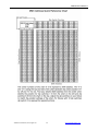
1
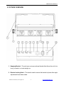
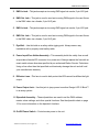
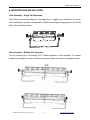
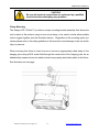
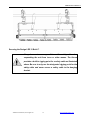
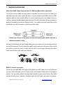
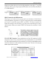
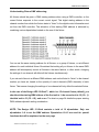
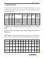
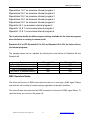
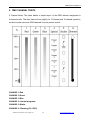
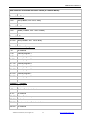
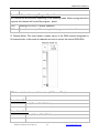
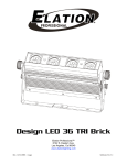
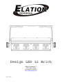
Design LED 12 Brick
Elation Professional™
4295 Charter Street
Los Angeles, Ca 90058
www.elationlighting.com
Rev. 01/24/07
DESIGN LED 12 BRICK™
©Elation Professional, Los Angeles Ca.
1
www.ElationLighting.com
DESIGN LED 12 BRICK™
TABLE OF CONTENS
CONTENTS
1.
General Information……………………………………………………………………… 3
a. Introduction………………………………………………………………………. 3
b. Unpacking………………………………………………………..…………..… 3
c.
Customer Support…………………………………………….………………… 3
d. Warranty Registration……………………………………………………..…… 4
2.
Safety Instructions………………………………………………………........…………. 5
3.
Features…………………………………………………………………………………… 7
4.
General Guidelines………………………………………………………………………. 8
5.
Fixture Overview…………………………………………………………………………. 9
6.
Mounting and Installation………………………………………………………….……. 11
a. Yoke Assembly………………………………………………………………….. 11
b. Mounting Positions……………………………………………………………… 13
c.
Mounting Points…………………………………………………………………. 13
d. Securing………………………………………………………………………….. 14
7.
Understanding DMX……………………………………………………………………... 16
a. DMX Connections………………………………………………………………. 16
b. DMX Terminator…………………………………………………………………. 17
c.
3-Pin to 5-Pin Conversion……………………………………………………….17
d. Understanding DMX Addressing.……………………………………………… 18
8.
Operation Modes….……………………………………………………………………… 19
a. DMX Mode Selection…………………………………………………………….19
b. Manual Settings…………………………………………………………………. 19
9.
DMX Traits………………………………………………………………………………… 22
a. 6-Channel Mode………………………………………………………………… 23
b. 12-Channel Mode…..…………………………………………………………… 24
c.
15-Channel Mode…..…………………………………………………………… 26
d. DMX Dipswitch Reference Chart……………………………………………… 29
10. Cleaning and Maintenance……………………………………………………………… 30
11. Warranty…………………………………………………………………………………... 31
12. Photometric Data………………………………………………………………………… 33
13. Dimensional Drawings………………………………………………….……………….. 34
14. Circuit Schematic………...………………………………………………………………. 35
15. Technical Specifications…………………………………………...………….………… 36
©Elation Professional, Los Angeles Ca.
2
www.ElationLighting.com
DESIGN LED 12 BRICK™
1. GENERAL INFORMATION
INTRODUCTION: Congratulations, you have just purchased one of the most innovative and
reliable LED fixtures on the market today! The Design LED 12 Brick,™ has been designed to
perform reliably for years when the guidelines in this booklet are followed. Please read and
understand the instructions in this manual carefully and thoroughly before attempting to
operate this unit. These instructions contain important information regarding safety during
use and maintenance.
UNPACKING: Thank you for purchasing the Design LED 12 Brick™ by Elation Professional®.
Every Design LED 12 Brick™ has been thoroughly tested and has been shipped in perfect
operating condition. Carefully check the shipping carton for damage that may have occurred
during shipping. If the carton appears to be damaged, carefully inspect your fixture for
damage and be sure all accessories necessary to operate the fixture have arrived intact. In
the event damage has been found or parts are missing, please contact our customer support
team for further instructions. Inside the box you should find: the fixture, a DMX XLR cable, a
safety cable, and this manual. Please do not return this unit to your dealer without first
contacting customer support at the number listed below.
CUSTOMER SUPPORT: Elation Professional® provides a customer support line, to provide
set up help and to answer any question should you encounter problems during your set up or
initial operation. You may also visit us on the web at www.elationlighting.com for any
comments or suggestions. For service related issue please contact Elation Professional®.
Service Hours are Monday through Friday 9:00 a.m. to 5:00 p.m. Pacific Standard Time.
Voice:
(323) 582-3322
Fax:
(323) 582-3108
E-mail:
Forum:
[email protected]
www.ElationLighting.com/forum
Warning! To prevent or reduce the risk of electrical shock or fire, do not expose this unit to
rain or moisture.
Caution! There are no user serviceable parts inside this unit. Do not attempt any repairs
©Elation Professional, Los Angeles Ca.
3
www.ElationLighting.com
DESIGN LED 12 BRICK™
yourself. Doing so will void your manufactures warranty.
Please do not discard the shipping carton in the trash. Please recycle whenever possible.
WARRANTY REGISTRATION: The Design LED 12 Brick™ carries a two year (730 days)
limited warranty. Please fill out the enclosed warranty card to validate your purchase. All
returned service items whether under warranty or not, must be freight pre-paid and
accompany a return authorization (R.A.) number. The R.A. number must be clearly written on
the outside of the return package. A brief description of the problem as well as the R.A.
number must also be written down on a piece of paper and included in the shipping container.
If the unit is under warranty, you must provide a copy of your proof of purchase invoice. Items
returned without a R.A. number clearly marked on the outside of the package will be refused
and returned at customer’s expense. You may obtain a R.A. number by contacting customer
support at (323) 582-3322.
©Elation Professional, Los Angeles Ca.
4
www.ElationLighting.com
DESIGN LED 12 BRICK™
2. SAFETY INSTRUCTIONS
To guarantee proper and consistent operation, it is important to
follow the guidelines in this manual. Elation Professional will not
accept responsibility for damages resulting from the misuse of
this fixture due to the disregard of the information printed in this
manual.
1. Always be sure that the fan and the air inlets remain clean and are never blocked.
Allow about 6” (15cm) between this fixture and other devices or a wall to allow for
proper cooling.
2. Never touch the fixture during normal operation.
3. Never look directly into the lamp beam. You risk injury to your retina, which may
induce blindness.
4. For safe operation, follow the Installation guide described in chapter two of this
manual. Operating the Design LED 12 Brick™ without suited safety aids such as
safety cables or clamps can increase the risk of damage and/or personal injury.
5. Installation should only be performed by qualified and certified personal.
6. When mounting this fixture, use only the original rigging points included with this
fixture. Any structural modification will void the original manufactures warranty
and may increase the risk of damage and/or personal injury.
7. To reduce the risk of fire or shock, do not expose this fixture to rain or moisture.
8. Do not attempt to operate this fixture if the power cord has become damaged or
frayed.
9. Never open this fixture while in use.
10. This device falls under protection-class I. Therefore it is essential that the device
be grounded properly.
11. All electrical connections must performed by qualified personal.
12. Be sure the available voltage matches the voltage requirements of the unit. Be
sure the power cord is never crimped or damaged. If the power cord is damaged,
©Elation Professional, Los Angeles Ca.
5
www.ElationLighting.com
DESIGN LED 12 BRICK™
replace it immediately with a new one of similar power rating.
13. Always disconnect from main power before performing any type of service or any
cleaning procedure.
14. Only handle the power cord by the plug. Never pull out the plug by tugging the
wire portion of the cord.
15. Please be aware that damages caused by modifications to the device are
not subject to warranty.
Important Notice: Damages resulting from the disregard of safety and general user
instructions found in this user manual are not subject to any warranty claims.
Never touch the device during operation!
The housing may heat up
Never look directly into the light source,
as sensitive persons may suffer an epileptic shock.
©Elation Professional, Los Angeles Ca.
6
www.ElationLighting.com
DESIGN LED 12 BRICK™
3. FEATURES
•
Low power consumption
•
Minimal heat emission
•
Maintenance free operation
•
Equipped with 12 one-watt LEDs: (4 red, 4 blue, 4 green)
•
High power LEDs manufactured by Lumileds, USA
•
100,000 hours rated LED life
•
Step less RGB color changing
•
USITT DMX-512 Complaint
•
Preprogrammed colored macros
•
Strobe-effect with a maximum flash rate of 18fps
•
DMX-controlled operation or stand-alone operation with Master/Slave-function
•
8 built-in programs can be called up via DMX-controller
~ 48 preprogrammed scenes per a program
•
Sound-controlled via built-in microphone
•
Three DMX Modes:
15 DMX-channel
12 DMX-channel
6 DMX-channel
•
DMX-control via standard DMX-controller
•
Flicker-free operation for television and film
•
Compact design: fits in 12” box truss
•
Brilliant light output
©Elation Professional, Los Angeles Ca.
7
www.ElationLighting.com
DESIGN LED 12 BRICK™
4. GENERAL GUIDELINES
This fixture is a professional lighting effect designed for use on stage, in nightclubs, in
theatres, and other types of architectural installations. Do not attempt operation or installation
without a proper knowledge on how to do so.
This fixture was designed for indoor use only; use of this fixture outside will void the
manufacture’s warranty.
Consistent operational breaks will ensure that the fixture will function properly for many years
to come.
Do not shake the fixture around. Avoid brute force when installing or operating the fixture.
While choosing an installation location, please be sure that the fixture will not be exposed to
extreme heat, moisture, or dust. The minimum distance between the fixture and a wall or flat
surface should be at least .5 meter (about 1.5ft).
Always install the fixture with an appropriately rated safety cable. When installing the fixture in
a suspended environment always be sure to use mounting hardware no less than M10 x 25
mm, also be sure the hardware is only inserted in the yoke’s mounting holes.
Do not attempt to operate this fixture until you have familiarized yourself with all of its
functions.
Do not permit operation by persons not qualified for operating this type of theatrical fixture.
Most damages are the result of improper operation.
Please use the original packaging to transport the fixture in for service.
For your own safety, please read this user manual carefully before installing the device.
©Elation Professional, Los Angeles Ca.
8
www.ElationLighting.com
DESIGN LED 12 BRICK™
5. FIXTURE OVERVIEW
1. Hanging Bracket – The unit uses a unique sectional bracket that allows the unit to be
hung, mounted, or stood straight up.
2. Bracket Locking Knob – This knob is used to secure the bracket in place after angle
adjustments have been made.
©Elation Professional, Los Angeles Ca.
9
www.ElationLighting.com
DESIGN LED 12 BRICK™
3. DMX In Jack – This jack accepts an incoming DMX signal via a male, 5-pin XLR jack.
4. DMX Out Jack – This jack is used to send an incoming DMX signal to the next fixture
in the DMX chain via a female, 5-pin XLR jack.
5. DMX In Jack – This jack accepts an incoming DMX signal via a male, 3-pin XLR jack.
6. DMX Out Jack – This jack is used to send an incoming DMX signal to the next fixture
in the DMX chain via a female, 3-pin XLR jack.
7. Eye-Bolt – Use this bold as a safety-cable rigging point. Always secure any
installation with a properly rated safety-cable.
8. Power Input/Fuse Holder Assembly – This assembly holds the safety fuse as well
as provides a female IEC connector for a power cord. Always replace the fuse with an
exact match unless otherwise specified by an authorized Elation Service Technician.
Using a fuse other than that specified could seriously damage the unit and will void
your manufactures warranty.
9. Diffusion Lens – This lens is used to both protect the LEDs as well as diffuse the light
output.
10. Power Output Jack – Use this jack to jump power to another Design LED 12 Brick™
in an array system.
11. Dipswitch Assembly – These dipswitches are used to set the DMX address,
master–slave settings, and other special functions. See the dipswitch chart on page
16 for more information on the dipswitch functions.
12. On/Off Power Switch – Controls main power to the unit.
©Elation Professional, Los Angeles Ca.
10
www.ElationLighting.com
DESIGN LED 12 BRICK™
6. MOUNTING AND INSTALLATION
Yoke Assembly – Single Unit Operation
The device can be placed directly on the stage floor or rigged in any orientation on a truss
without altering its operation characteristics. When connecting the hanging yoke to the fixture,
refer to the illustration below.
Yoke Assembly – Multiple Unit Operation
You can connect up to four Design LED 12 Bricks together in a bar assembly. To connect
multiple units together use the included mounting hardware and refer to the diagram below.
©Elation Professional, Los Angeles Ca.
11
www.ElationLighting.com
DESIGN LED 12 BRICK™
Please note: To ensure maximum stability, no more than for units should be mounted
together in this fashion. Connecting more than four units will result in an unstable
assembly, which could collapse and damage the units.
Cautions:
For added protection mount the fixtures in areas outside walking paths, seating areas, and
away from areas were the fixture might be reached by unauthorized personal.
Before mounting the fixture to any surface, make sure that the installation area can hold a
minimum point load of 10 times the device’s weight.
Fixture installation must always be secured with a secondary safety attachment, such as an
appropriate safety cable.
To avoid injury, never stand directly below the device when mounting, removing, or servicing
the fixture.
Refer to regulations BGV C1 (formerly VBG 70) and DIN VDE0711-217
for proper installation in Europe To ensure proper installation, only
qualified staff should attempt installation.
Mounting points
Overhead mounting requires extensive experience, including amongst others calculating
working load limits, a fine knowledge of the installation material being used, and periodic
safety inspection of all installation material and the fixture. If you lack these qualifications, do
not attempt the installation yourself. Improper installation can result in bodily injury.
Be sure to complete all rigging and installation procedures before connecting the main power
cord to the appropriate wall outlet.
©Elation Professional, Los Angeles Ca.
12
www.ElationLighting.com
DESIGN LED 12 BRICK™
Mounting
The Design LED 12 Brick™ is fully operational in three different mounting positions, hanging
upside-down from a ceiling, side mounted, or set on a flat level surface. Be sure this fixture is
kept at least 0.5m away from any flammable materials (decoration etc.). When clamp
mounting; always use and install the supplied safety cable as an added safety measure to
prevent accidental damage in the event of a clamp failure. See the image below.
©Elation Professional, Los Angeles Ca.
13
www.ElationLighting.com
DESIGN LED 12 BRICK™
CAUTION!
Be sure all electrical connections are performed by a qualified
electrician before attempting any operation.
Clamp Mounting
The Design LED 12 Brick™ provides a unique mounting bracket assembly that allows the
unit to stand on flat surface, hang on truss via a clamp, or be used in cluster allow multiple
units to rigged together (see the illustration below). Regardless of the mounting option you
choose please refer to the safety guidelines in this manual to avoid damage to the unit and/or
injury to persons.
When mounting this fixture to truss be sure to secure an appropriately rated clamp to the
hanging yoke using a M10 screw fitted through the center hole of the hanging yoke. As an
added safety measure be sure to attach at least one properly rated safety cable to the fixture.
See illustration on next page.
©Elation Professional, Los Angeles Ca.
14
www.ElationLighting.com
DESIGN LED 12 BRICK™
Securing the Design LED 12 Brick™
Always be sure to secure your fixture with a safety cable when
suspending the unit from truss or other means. The fixture
provides a built-in rigging point for a safety cable as illustrated
above. Be sure to only use the designated rigging point for the
safety cable and never secure a safety cable to the hanging
bracket.
©Elation Professional, Los Angeles Ca.
15
www.ElationLighting.com
DESIGN LED 12 BRICK™
7. UNDERSTANDING DMX
Data Cable (DMX Cable) Requirements (For DMX and Master/Slave Operation):
Your fixture and your DMX controller require a standard 3-pin XLR connector for data input
and data output (see figure below). Be sure to only use properly rated DMX cables for DMX
operation and not standrd audio cables. If you are constructing your own cables be sure to
use two conductor shielded digital cable rated at a 120 ohms (this cable can be purchased at
almost all professional sound and lighting stores). Your cables should be made with a male
and female 3-pin XLR connector on either end of the cable.
Please note: This is not the same as audio microphone cable. Audio cable has a
different resistance rating
Be sure to follow the above figure when making your own cables. Do not use the ground lug
on the XLR connector. Do not connect the cable’s shield conductor to the ground lug or allow
the shield conductor to come in contact with the XLR’s outer casing. Grounding the shield
could cause a short circuit and erratic behavior.
DMX-512 control connection
Connect the provided DMX XLR cable to the female 3-pin XLR output of your controller and
the other side to the male 3-pin XLR input of the moving head (Please refer to the diagram
below.). You can chain multiple moving heads together through serial linking. The cable
needed should be two conductor, shielded cable with XLR input and output connectors.
©Elation Professional, Los Angeles Ca.
16
www.ElationLighting.com
DESIGN LED 12 BRICK™
Always be sure daisy chain your in and out data connections, never split or “Y” your DMX
connections unless you are using an approved DMX splitter such as the Elation Opto Branch
4™ or DMX Branch/4™.
DMX-512 connection with DMX terminator
When longer runs of cable are used, you may need to use a terminator on the last fixture to
avoid erratic behavior. A terminator is a 120 ohm 1/4 watt resistor that is connected between
pins 2 and 3 of a male XLR connector (DATA + and DATA -). This fixture is inserted in the
female XLR connector of the last fixture in your daisy chain to terminate the line. Using a
cable terminator (Elation part number Z-DMX/T) will decrease the possibilities of erratic
behavior.
5-Pin XLR DMX Connectors. Some manufactures use 5-pin XLR connectors for DATA
transmission in place of 3-pin. 5-pin XLR fixtures may be implemented in a 3-pin XLR DMX
line. When inserting standard 5-pin XLR connectors in to a 3-pin line a cable adaptor must be
used, these adaptors are readily available at most electric stores. The chart on the next page
details a proper cable conversion.
©Elation Professional, Los Angeles Ca.
17
www.ElationLighting.com
DESIGN LED 12 BRICK™
Understanding Fixture DMX addressing;
All fixtures should be given a DMX starting address when using a DMX controller, so the
correct fixture responds to the correct control signal. This digital starting address is the
channel number from which the fixture starts to “listen” to the digital control information sent
out from the DMX controller. The allocation of this starting DMX address is achieved by
combining various dipswitches located on the rear of the fixture.
You can set the same starting address for all fixtures, or a group of fixtures, or set different
address for each individual fixture. Be advised that setting all you fixtures to the same DMX
address will subsequently control all fixtures in the same fashion, in other words, changing
the settings of one channel will affect all the fixtures simultaneously.
If you set each fixture to a different DMX address, each unit will start to “listen” to the channel
number you have set, based on the quantity of control channels (DMX channels) of each
fixture. That means changing the settings of one channel will only affect the selected fixture.
In the case of the Design LED 12 Brick™, which is a 15 channel fixture (default), you
should set the starting DMX address of the first unit to 1, the second unit to 16 (15 + 1),
the third unit to 31 (15 + 16), and so on. The chart on page 24 details the proper starting
DMX address dipswitch setting combination.
NOTE: The Design LED 12 Brick contains a total of 12 dipswitches. Only use
dipswitches 1~9 to set the DMX address. Dipswitches 10~12 are used for special
functions that will be explained on the next page.
©Elation Professional, Los Angeles Ca.
18
www.ElationLighting.com
DESIGN LED 12 BRICK™
8. OPERATING MODES
This fixture can run in three different DMX modes. The chart below describes how to access
the different DMX modes. The chart below also defines the how the channel will function in
the different DMX modes.
DMX
Operation
mode
DIP
#12
DIP
#11
LED control Mode
LEDs
control
channels
Preset
programs
channel
Strobe
channel
Master
dimming/
program
speed
15CH
OFF
OFF
1~12
13
14
15
12CH
OFF
ON
6CH
ON
OFF
Each Led can be run
individually
Each Led can be run
individually
R, G, B run by group
4
5
6
1~12
1~3
Dipswitches 11 & 12: DMX Mode Selection, See the chart above; 15, 12, or 6 channel
modes.
Dipswitch 10: Sound-active operation when used as a single stand-alone unit or
“master” unit.
Manual Settings: The chart bellows details the dipswitch setting for various manual settings.
Refer to the chart on page 20 for specific static color settings and internal program access.
Operating
Mode:
Dip
# 11
Dip
#10
Dip
#9
Dip
#8
Dip
#7
Dip
#6
Dip
#5
Dip
#4
Dip
#3
Dip
#2
Dip
#1
No function
OFF
OFF
N/A
N/A
N/A
N/A
N/A
N/A
N/A
N/A
N/A
Sound
control-Stand
Alone
OFF
ON
N/A
N/A
N/A
N/A
N/A
N/A
N/A
N/A
N/A
Static R, G, B
(Refer to
Table 3)
ON
OFF
N/A
N/A
OFF
Blue
Blue
Red
Red
Preset
Program 1
ON
OFF
ON
OFF
OFF
OFF
ON
Speed Speed
©Elation Professional, Los Angeles Ca.
19
Green Green
OFF
OFF
www.ElationLighting.com
DESIGN LED 12 BRICK™
Preset
Program 2
ON
OFF
ON
OFF
OFF
OFF
OFF
ON
OFF
Preset
Program 3
ON
OFF
ON
OFF
OFF
OFF
ON
OFF
OFF
Preset
Program 4
ON
OFF
ON
OFF
OFF
ON
OFF
OFF
OFF
Preset
Program 5
ON
OFF
ON
OFF
ON
OFF
OFF
OFF
OFF
Preset
Program 6
ON
OFF
ON
ON
OFF
OFF
OFF
OFF
OFF
Preset
Program 7
ON
OFF
ON
OFF
OFF
OFF
OFF
ON
ON
Preset
Program 8
ON
OFF
ON
OFF
OFF
OFF
ON
OFF
ON
Manual static color settings are achieved when dipswitch 7 is in the “off” position.
RED:
Dipswitch 1 & 2 off, the red value is 0
Dipswitch 1 is on and dipswitch 2 is off, the red value is 60
Dipswitch 1 is off and dipswitch 2 is on, the red value is 125
Dipswitch 1 is on and dipswitch 2 is on, the red value is 255
GREEN:
Dipswitch 3 & 4 off, the green value is 0
Dipswitch 3 is on and dipswitch 4 is off, the green value is 60
Dipswitch 3 is off and dipswitch 4 is on, the green value is 125
Dipswitch 3 is on and dipswitch 4 is on, the green value is 255
BLUE:
Dipswitch 5 & 6 is off, the blue value is 0
Dipswitch 5 is on and dipswitch 6 is off, the blue value is 60
Dipswitch 5 is off and dipswitch 6 is on, the blue value is 125
Dipswitch 5 is on and dipswitch 6 is on, the blue value is 255
When dipswitch 7 is on you can run the internal program
©Elation Professional, Los Angeles Ca.
20
www.ElationLighting.com
DESIGN LED 12 BRICK™
Dipswitches 1 & 7 on accesses internal program 1
Dipswitches 2 & 7 on accesses internal program 2
Dipswitches 3 & 7 on accesses internal program 3
Dipswitches 4 & 7 on accesses internal program 4
Dipswitches 5 & 7 on accesses internal program 5
Dipswitch 6 & 7 on accesses internal program 6
Dipswitch 1,2 & 7 on accesses internal program 7
Dipswitch 1,3 & 7 on accesses internal program 8
The chart below details the different speed settings available for the internal programs
when the fixture is running in manual mode.
Dipswitch # 10 is OFF, Dipswitch #11 is ON, and Dipswitch #7 is ON, the fixture will run
the internal programs;
The program speed can be adjusted by following the chart below for Dipswitch #8 and
Dipswitch #9
Speed
Slow (1.1s between scenes)
Medium (0.6s between scenes)
Fast (0.2s between scenes)
Very fast (0.1s between scenes)
Dipswitch #8
OFF
ON
OFF
ON
Dipswitch #9
OFF
OFF
ON
ON
DMX Operation Notes:
The fixture will function in DMX mode whenever the unit is receiving a DMX signal. Please
note that this will override all manual settings regardless of dipswitch positions.
This unit will keep and retain the last DMX command in the event of DMX signal failure. To
reset the fixture you must turn the power off.
©Elation Professional, Los Angeles Ca.
21
www.ElationLighting.com
DESIGN LED 12 BRICK™
9. DMX CHANNEL TRAITS
6 Channel Mode: This chart details a simple layout of the DMX channel assignment in
6-channel mode. The chart traits will vary slightly for 12 channel and 15-channel operation,
as those modes use more RGB channels for more precise control.
CHANNEL 1:Red
CHANNEL 2:Green
CHANNEL 3:Blue
CHANNEL 4: Internal programs:
CHANNEL 5:Strobe
CHANNEL 6: Dimming (0%-100%)
©Elation Professional, Los Angeles Ca.
22
www.ElationLighting.com
DESIGN LED 12 BRICK™
DMX channel’s functions and their values (6 Channel Mode):
Channel 1 - Red:
0-255
Red (0-Black, 255-100% Red)
Channel 2 - Green:
0-255
Green (0-Black, 255- 100% Green)
Channel 3 - Blue:
221-255 Blue (0-Black, 255- 100% Blue)
Channel 4 - Internal programs:
0-10
No function
11-40
Internal program 1
41-70
Internal program 2
71-100
Internal program 3
101-130 Internal program 4
131-160 Internal program 5
161-190 Internal program 6
191-220 Internal program 7
221-255 Internal program 8
Channel 5 - Strobe:
0
No function
1~95
Strobe effect slow to fast
96-127
No function
128-159 Pulse effect in sequences
160-191 No function
192-223 Random strobe effect slow to fast
224-255 No function
©Elation Professional, Los Angeles Ca.
23
www.ElationLighting.com
DESIGN LED 12 BRICK™
Channel 6 - General dimming / Program Speed Control
This channel has two functions depending on the operating mode. When running the built-in
programs this channel will control the program speed.
0-255
Dimming (0%-100%) ~ Normal Operation
0-255
Speed (min to max) ~ When running built-in programs on channel 4
12 Channel Mode: This chart details a simple layout of the DMX channel assignment in
12-channel mode. In this mode all channels are used to control the various RGB LEDs.
DMX channel’s functions and their values (12 Channel Mode):
Channel 1 - Red:
0-255
Red (0-Black, 255-100% Red)
Channel 2 - Green:
0-255
Green (0-Black, 255- 100% Green)
©Elation Professional, Los Angeles Ca.
24
www.ElationLighting.com
DESIGN LED 12 BRICK™
Channel 3 - Blue:
221-255
Blue (0-Black, 255- 100% Blue)
Channel 4 - Red:
0-255
Red (0-Black, 255-100% Red)
Channel 5 - Green:
0-255
Green (0-Black, 255- 100% Green)
Channel 6 - Blue:
221-255
Blue (0-Black, 255- 100% Blue)
Channel 7 - Red:
0-255
Red (0-Black, 255-100% Red)
Channel 8 - Green:
0-255
Green (0-Black, 255- 100% Green)
Channel 9 - Blue:
221-255
Blue (0-Black, 255- 100% Blue)
Channel 10 - Red:
0-255
Red (0-Black, 255-100% Red)
Channel 11 - Green:
0-255
Green (0-Black, 255- 100% Green)
Channel 12 - Blue:
221-255
Blue (0-Black, 255- 100% Blue)
©Elation Professional, Los Angeles Ca.
25
www.ElationLighting.com
DESIGN LED 12 BRICK™
15 Channel Mode: This chart details a simple layout of the DMX channel assignment in
15-channel mode. In this mode channels 1~12 are used to control the various RGB LEDs and
channels 13~15 will control special features.
DMX channel’s functions and their values (15 Channel Mode):
Channel 1 - Red:
0-255
Red (0-Black, 255-100% Red)
Channel 2 - Green:
0-255
Green (0-Black, 255- 100% Green)
Channel 3 - Blue:
221-255 Blue (0-Black, 255- 100% Blue)
Channel 4 - Red:
0-255
Red (0-Black, 255-100% Red)
©Elation Professional, Los Angeles Ca.
26
www.ElationLighting.com
DESIGN LED 12 BRICK™
Channel 5 - Green:
0-255
Green (0-Black, 255- 100% Green)
Channel 6 - Blue:
221-255 Blue (0-Black, 255- 100% Blue)
Channel 7 - Red:
0-255
Red (0-Black, 255-100% Red)
Channel 8 - Green:
0-255
Green (0-Black, 255- 100% Green)
Channel 9 - Blue:
221-255 Blue (0-Black, 255- 100% Blue)
Channel 10 - Red:
0-255
Red (0-Black, 255-100% Red)
Channel 11 - Green:
0-255
Green (0-Black, 255- 100% Green)
Channel 12 - Blue:
221-255 Blue (0-Black, 255- 100% Blue)
Channel 13 - Internal programs:
0-10
No function
11-40
Internal program 1
41-70
Internal program 2
71-100
Internal program 3
©Elation Professional, Los Angeles Ca.
27
www.ElationLighting.com
DESIGN LED 12 BRICK™
101-130 Internal program 4
131-160 Internal program 5
161-190 Internal program 6
191-220 Internal program 7
221-255 Internal program 8
Channel 14 - Strobe:
0
No function
1~95
Strobe effect slow to fast
96-127
No function
128-159 Pulse effect in sequences
160-191 No function
192-223 Random strobe effect slow to fast
224-255 No function
Channel 15 - General dimming / Program Speed Control
This channel has two functions depending on the operating mode. When running the built-in
programs this channel will control the program speed.
0-255
Dimming (0%-100%) ~ Normal Operation
0-255
Speed (min to max) ~ When running built-in programs on channel 4
©Elation Professional, Los Angeles Ca.
28
www.ElationLighting.com
DESIGN LED 12 BRICK™
©Elation Professional, Los Angeles Ca.
29
www.ElationLighting.com
DESIGN LED 12 BRICK™
10. CLEANING AND MAINTENANCE
The consider the following point during normal service and inspection:
1. Be sure all screws and fasteners are securely tightened at all times. Lose screws may
fall out during normal operation resulting in damage or injury as larger parts could fall.
2. Electric power supply cables must not show any damage, material fatigue or
sediments. Never remove the ground prong from the power cable.
Further instructions depending on the installation spot and usage have to be adhered by a
skilled installer and any safety problems have to be removed.
Disconnect from mains before starting maintenance operation.
We recommend a frequent cleaning of the device. Please use a moist, lint- free cloth. Never
use alcohol or solvents.
There are no user serviceable parts inside this, please refer all other service issues to an
authorized Elation service technician.
Should you need any spare parts, please order genuine parts from your local dealer.
©Elation Professional, Los Angeles Ca.
30
www.ElationLighting.com
DESIGN LED 12 BRICK™
11.
2-YEAR LIMITED WARRANTY
A. Elation Professional® hereby warrants, to the original purchaser, Elation Professional®
products to be free of manufacturing defects in material and workmanship for a period of two
years, (730 days) from the date of purchase. This warranty shall be valid only if the product is
purchased within the United States of America, including possessions and territories. It is the
owner’s responsibility to establish the date and place of purchase by acceptable evidence, at
the time service is sought.
B. For warranty service, send the product only to the Elation Professional® factory. All
shipping charges must be pre-paid. If the requested repairs or service (including parts
replacement) are within the terms of this warranty, Elation Professional® will pay return
shipping charges only to a designated point within the United States. If the entire instrument is
sent, it must be shipped in its original package. No accessories should be shipped with the
product. If any accessories are shipped with the product, Elation Professional® shall have no
liability what so ever for loss of or damage to any such accessories, nor for the safe return
thereof.
C.
This warranty is void if the serial number has been altered or removed; if the product is
modified in any manner which Elation Professional® concludes, after inspection, affects the
reliability of the product; if the product has been repaired or serviced by anyone other than the
Elation Professional® factory unless prior written authorization was issued to purchaser by
Elation Professional®; if the product is damaged because not properly maintained as set forth
in the instruction manual.
D. This is not a service contract, and this warranty does not include maintenance, cleaning
or periodic check-up. During the period specified above, Elation Professional® will replace
defective parts at its expense, and will absorb all expenses for warranty service and repair
labor by reason of defects in material or workmanship. The sole responsibility of Elation
Professional® under this warranty shall be limited to the repair of the product, or replacement
thereof, including parts, at the sole discretion of Elation Professional®. All products covered by
this warranty were manufactured after January 1, 1990, and bare identifying marks to that
©Elation Professional, Los Angeles Ca.
31
www.ElationLighting.com
DESIGN LED 12 BRICK™
effect.
E. Elation Professional® reserves the right to make changes in design and/or improvements
upon its products without any obligation to include these changes in any products theretofore
manufactured.
F.
No warranty, whether expressed or implied, is given or made with respect to any
accessory supplied with products described above. Except to the extent prohibited by
applicable law, all implied warranties made by Elation Professional® in connection with this
product, including warranties of merchantability or fitness, are limited in duration to the
warranty period set forth above. And no warranties, whether expressed or implied, including
warranties of merchantability or fitness, shall apply to this product after said period has
expired. The consumer’s and or Dealer’s sole remedy shall be such repair or replacement as
is expressly provided above; and under no circumstances shall Elation Professional® be
liable for any loss or damage, direct or consequential, arising out of the use of, or inability to
use, this product.
G. This warranty is the only written warranty applicable to Elation Professional® Products
and supersedes all prior warranties and written descriptions of warranty terms and conditions
heretofore published.
©Elation Professional, Los Angeles Ca.
32
www.ElationLighting.com
DESIGN LED 12 BRICK™
12.
PHOTOMETRIC DATA
Distance
1m
2m
3m
Diameter
0.8m
1.6m
2.4m
A1
480
144
76
©Elation Professional, Los Angeles Ca.
B1
368
129
68
33
B2
370
129
74
B3
340
124
72
B4
304
122
69
Average
372
648
72
www.ElationLighting.com
Angle
44°
44°
44°
DESIGN LED 12 BRICK™
13.
DIMENSIONAL DRAWINGS
©Elation Professional, Los Angeles Ca.
34
www.ElationLighting.com
DESIGN LED 12 BRICK™
15.
TECHNICAL SPECIFICATIONS
Power supply:
90V~250V AC50Hz~60Hz
Power consumption:
MAX
LED Configuration:
12 1Watt Units (3 x Red, 3x Green 3 x Blue)
Packing dimensions:
47x26.5x19cm (56x48x42cm ~ 4pc system)
Weight:
2.1Kgs / 4.62 Lbs (9.2Kgs ~ 4pc system)
DMX Channels:
15, 12, or 6 Channel mode
Drive:
Standard DMX-512, 3 pole XLR; [+] = Pin 3
30W
[-] = Pin 2
[Ground] = Pin 1.
Color Mixing:
RGB Color Additive Mixing
Beam Angle:
44˚
Fuse:
GMA 220v~3A
Dimmer:
Continuous Dimming 0~100%
Strobe:
Electronic Strobe 0~18 Fps
Lamp Life:
100,000 Hours Rated Life
Please Note: Specifications and improvements in the design of this unit and this manual are
subject to change without any prior written notice.
©Elation Professional, Los Angeles Ca.
35
www.ElationLighting.com
DESIGN LED 12 BRICK™
©Elation Professional, Los Angeles Ca.
36
www.ElationLighting.com
DESIGN LED 12 BRICK™
Elation Professional
4295 Charter Street
Los Angeles, CA. 90058
323-582-3322 / 323-582-3108 fax
www.ElationLighting.com /[email protected]
©Elation Professional, Los Angeles Ca.
37
www.ElationLighting.com