1
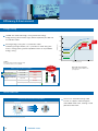
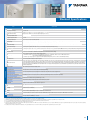
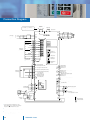
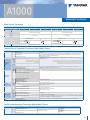
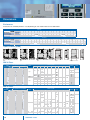
InvErtEr SErIES
HIGH PErformAncE vEctor control
A1000
En
DE
ES
fr
It
A1000
A1000
A1000
A1000
A1000
A1000
YASKAWA A1000 HIGH PErformANcE DrIVE
contents
content
Page 2
Experience & Innovation
A leader in Inverter Drives
technology
main features
Page 3
customize Your Drive
Page 4/5
Permanent magnet motor
control
Page 6/7
Safety features &
communication
Page 8/9
Easy start-up and reliable
operation
Page 10/11
Drive Design & features
Experience & Innovation
for
or more than 90 years YASKAWA has
been manufacturing and supplying
mechatronic products for machine
building and industrial automation. Its
standard products as well as tailor-made
solutions are famous and have a high
reputation for outstanding quality and
durability.
A leader in Inverter Drives
technology
Extensive research and development has
allowed YASKAWA to remain at the forefront
of motion control and automation technology.
This technological leadership has helped to
modernise industries such as mining, steel,
pulp and paper, chemical, automotive, pacpac
caging,
aging, machine tool and semiconductor.
In 2007 YASKAWA produced its 10 millionth
inverter in the new inverter plant in
Yuccuhashi, Japan. By this YASKAWA is
Yu
probably the biggest inverter manufacturer in
the world.
With the new A1000, YASKAWA continues
its tradition of developing innovative solutions
in drive technology. The A1000 provides
remar able advantages through excellent
motor drive performance, environmental
benefits and energy savings as well as
many user orientated operational features.
Moreover, the A1000 offers advanced
characteristics that are included as standard.
In response to the needs of users, we have
introduced next-generation product features
to A1000 vector control technology:
Page 12
Efficiency & Environment
Page 13
Specifications
main features:
Page 14
for Induction motor and Permanent magnet
f
Improved Drive Design & functions:
connection Diagram
motor control:
Small size and application oriented
The A1000 is a premium inverter drive for
design improve performance, reliability
Page 15
a wide field of applications including great
and performance life
Terminal functions
advantages in more than one way
Page 16/17
Dimensions
Using the A1000 saves energy and
Safety features of the A1000 comply with
reduces audible noise
today’s market safety requirements and
standards
Page 18
options
Page 19
ratings & Type Descriptions
2
Enhanced Efficiency & Environment:
Providing newest Safety features:
eliable operation:
YASKAWA A1000 provides significant costs
reduction potentials during installation and
operation
YASKAWA A1000
Permanent magnet motor control
Open loop position control
(No Motor Feedbacc)
Feedbacc)
c
200% rated torque at 0 rpm
New Auto-Tuning Features
Tuning of the Speed Loop according
to Load
Power Loss Recovery
Safety features & communication
Safety Torque Off (STO) according
to EN954-1 safety category 3, stop
category 0; EN ISO 13849-1 PLd;
IEC EN 61508 SiL2
External Device Monitor (EDM) to
Observe the Safety Status
Easy Start-up & reliable operation
Application Parameter Presets
Screwless Removable Control
Terminal with Parameter Bacc
Baccup
Online Auto-Tuning for Motor
Parameter
Tuning of the Speed Loop according
to Load
Parameter Copy and Bacc
Baccup
Function
Engineering Tool DriveWizard Plus for
Parameter Management
Application SW Library
Performance Life Diagnostics for all
major inverter components
Drive Design & functions
Even more compact
Side-by-Side Mounting
Dual Rating for Cost & Space Saving
Long Performance Life
Overexcitation Brac
Bracing to reduce
Deceleration Time
Efficiency & Environment
Advanced Energy Saving
Functionality
Unique PWM function reduces
audible noise.
Minimum Power Loss in Normal
Duty Rating
customize Your Drive
DriveWorcsEZ visual programming tool.
Simply drag and drop icons to customize your drive.
Create special sequences and detection functions,
then load them onto the drive.
create customized detection features
Example:
Machine weacening analysis using torque pulse detection
USB port lets the drive connect to a Pc
Example:
Sensorless positioning control function
(Available soon)
IPM motor
Home
position
Home
position
Speed
Reference
A1000
Time (s)
Detects fluctuation
within the specified range
Pulley
A1000
Torque
amplitude
Torque
Program a customized sequence
Example:
Sensorless positioning control function
(Available soon)
Feeding
Time setting
Motor
Time (s)
USB port
Note:
Drives are also equipped with an RJ-45 comm. port that takes the existing WV103 cable used in Yaskawa’s previous models. Simply remove the operator keypad for to the RJ-45 connector.
3
Advanced motor control
content
Advanced Drive Technology
Capable of driving different types of motor.
A1000 runs not only induction motors, but also
synchronous motors lice IPM*1 and SPM*2 motors with
high performance open and closed loop vector control.
Minimize equipment needed for your business by using
the same drive to run induction and synchronous motors.
Use parameters to switch
between motor types
A1000
*1 Interior Permanent Magnet Motor
(Motors with permanent magnets inserted into the rotor)
*2 Surface Mounted Permanent Magnet Motor
(Motors with permanent mangets mounted on the surface of the rotor)
Induction motor
Synchronous motor
(SPM)
SMRA Series
Synchronous motor
(IPM)
Super Energy-Saving Motor
Positioning capability without External Devices
Use an IPM motor to perform position control – without motor feedbacc.
Electrical saliency in IPM motors maces it possible to detect speed, direction and rotor
position without the use of external feedbaccc devices.
Positioning functionality without a PLC. Visual programming in DriveWorcsEZ
eliminates the need for external controllers by giving the user the power to create
customized functions such as position control.
PLC
No PG feedback needed
4
YASKAWA A1000
New Auto-Tuning Features
uto-Tuning features optimize drive parameters for operation with induction motors as
A
well as synchronous motors to achieve the highest performance levels possible.
ptimizing not only the drive and motor performance, but also automatically adjusts
O
settings relative to the connected machinery.
ew Auto-Tuning methods.
N
A1000 continuously analyzes changes in motor characteristics during operation for highly
precise speed control.
Tuning the Motor
Applications requiring high starting torque, high speed,
and high accuracy.
Applications where the motor must remain connected to
Stationary Auto-Tuning
the load during the tuning process.
For tuning after the cable length between the motor and
Line-to-Line Resistance
drive has changed, or when motor and drive capacity
Auto-Tuning
ratings differ.
Energy-Saving Auto-Tuning For running the motor at top efficiency all the time.
Rotational Auto-Tuning
Tuning the Load
ASR*Tuning
Inertia Tuning
Perfects responsiveness relative to the machine.
Until now, this tuning procedure was fairly time
consuming to set.
Optimizes the drive‘s ability to decelerate the load.
Useful for applications using Kinetic Energy Buffering
Function and Feed Forward functions.
* Automatic Speed Regulator
Powerful Torque Characteristics
Torque characteristics
Advanced Open Loop Vector with an IPM motor
200
Powerful torque at 0 Hz
igh-performance current vector control achieves powerful starting torque with an
H
induction motor.
Torque (%)
owerful torque at 0 Hz, without sensors or feedback devices.
P
Until recently, sensorless control has been out of reach for synchronous
motors. Now A1000 provides powerful starting torque algorithm without
relying on pole sensors or motor feedback.
100
0
1000
1800
Motor Speed (r/min)
Synchronous Motor
Advanced Open Loop
200% rated torque at 0 r/min*, speed range of 1:100*
Vector for PM motors
Closed Loop Vector Control
200% rated torque at 0 r/min, speed range of 1:1500
for PM motors
* only IPM motor
Induction Motor
Open Loop Vector Control
200% rated torque at 0.3 Hz*, speed range of 1:200
Closed Loop Vector Control 200% rated torque at 0 r/min*, speed range of 1:1500
*Proper output torque depends on matching drive and motor capacity.
5
Safety features & communication
Power Loss & recovery
Speed Search
Easily find the speed
of a coasting motor
for a smooth restart.
Power supply
voltage
Applications
Perfect for fans,
blowers and other
rotating, fluid-type
applications.
Motor speed
Output frequency
1750 r/min
A1000 offers two ways to handle momentary power loss
A1000 is capable of handling momentary power loss
with sensorless control for induction motors as well as for
synchronous motors.
A1000 lets you ride through a power loss for up to
2 seconds.*
1750 r/min
Suppresses overcurrent for
a fast, smooth start
* Option available for certain models.
Output current
Kinetic Energy
Buffering
Ride-Through
Keep the motor
running without
allowing it to coast.
Power supply
voltage
Motor speed
Output frequency
1750 r/min
1750 r/min
1750 r/min
Uses regenerative energy to keep
the application running
Output current
Note: Separate sensor to detect power loss are required.
Applications
Should a power
outage occur,
A1000 can bring
the application to
controlled stop
quickly using the
Kinetic Energy
Buffering function.
Highly recommended
for film lines, textile
machinery, and
other applications
requiring continuous
operation.
Protective Design
A variety of protective designs are available to
reinforce the drive against moisture, dust, oil mist, vibration,
corrosive sulfur gas, conductive particles, and other harsh
environments.
6
YASKAWA A1000
IP54, dust proof and splash-waterproof options are also
available
RoHS Compliance
Safety features as a Standard
A1000 provides Safe Torque Off (STO) functional safety in
compliance with EN954-1 safety category 3 stop category
0, EN ISO 13849-1, PLd, IEC/EN61508 SIL2.
An External Device Monitor (EDM) function has also been
added to monitor the safety status of the drive.
EN954-1 Safety Cat. 3
Compliance
Power
supply
Controller
Safety
controller
Feedback loop
Motor
All major Serial communication Protocols
RS-422/485 (MEMOBUS/Modbus at 115.2 cbps)
standard on all models.
Option cards available for all major fieldbuses used across
the globe:
LONWORKS®
LONWORKS®
LONWORKS®
LONWORKS®
LONWORKS®
* Registered trademarks of those companies.
7
Easy start-up and reliable operation
Application Parameter Presets
A1000 automatically sets parameters needed for major
applications. Selecting the appropriate application
optimizes the drive for top performance, while saving time
for set up.
Crane (Traverse)
Setting
00
01
02
03
04
05
06
07
Crane (Hoist)
Conveyor
Compressor
Fan
Pump
Setting
General-purpose
Water Supply Pump
Conveyor
Exhaust Fan
HVAC Fan
Air Compressor
Crane (Hoist)
Crane (Traverse)
Parameters are programmed
automatically
A1-02
C1-01
C1-02
C6-01
Control mode selection
Accel Time 1
Decel Time
ND/HD Selection
Example using Application Presets
Selecting “Conveyor” optimizes parameter settings so the drive is ready to start your conveyor application immediately
more …
multifunction Terminal Block
The first terminal board with a Parameter Baccup Function
The terminal blocc’s ability to save parameter setting data
maces it easy to get the application baccc online in the
event of a failure requiring drive replacement.
Parameter
A1000 Terminal Block
8
YASKAWA A1000
Name
Number
Setting
ND/HD
C6-01
1
Control Mode
A1-02
0
Frequency Reference Selection
b1-01
1
Run Command Selection
b1-02
1
Parameter copy function
All standard models are equipped with a Parameter
Copy Function that allows parameter settings to be easily
copied from the drive or uploaded for quiccc setup using
the operator.
A USB Copy Unit is also available as an even faster, more
convenient way to baccc up settings and instantly program
the drive.
Engineering Tool DriveWizard Plus
Engineering Tool DriveWizard Plus
Drive Replacement Function
Previous Model
A1000
Manage the unique settings for all your drives right on your
PC.
Varispeed F7
Instant setup
Varispeed F7S
DriveWizard Plus
Note: To obtain a copy of DriveWitard Plus, contact a Yaskawa representative.
An indispensable tool for drive setup and maintenance.
Edit parameters, access all monitors, create customized
operation sequences, and observe drive performance with
the oscilloscope function.
The Drive Replacement feature in DriveWizard Plus
saves valuable time during equipment replacement and
application upgrades by converting previous Yascawa
product parameter values to the new A1000 parameters
automatically.
9
Drive Design & features
content
Even more compact
Yascawa continues to
mace applications even
smaller by combining the
compact designed drive
with the light, efficient
design of a synchronous
motor.
Comparing drive dimensions
Comparing motor dimensions
Example: 400 V Class 75 kW
Example shows a 200 V 3.7 kW motor
F7
Previous
model
55.4%
smaller
Synchronous motor
SMRA Series
A1000
Use Side-by-Side
installation for an even
more compact setup.
70%
Induction motor
smaller
Finless models available*.
* Coming soon
Dual rating for cost & Space Saving
Each drive lets the user
choose between Normal
Duty or Heavy Duty
operation. Depending on
the application, A1000
can run a motor an entire
frame size larger than our
previous model.
Select the drive rating that best fits the application needs
Previous Model
A1000 (Normal Duty)
11 kW motor requires a 11 kW drive.
7.5 kW drive can now run a 11 kW motor–
an entire frame size larger
11 kW
motor
11 kW
motor
11 kW
7.5 kW
Dual Ratings in A1000
A single parameter lets the user set the drive for Normal Duty or Heavy Duty
A1000
7.5 kW/11 kW
Motor
Applications
Heavy Duty
7.5 kW
motor
150% inverter rated current for 1 minute
Normal Duty
11 kW
motor
120% inverter rated current for 1 minute
Note: Always select a drive with a current rating greater than the motor rated current.
10
YASKAWA A1000
Long Performance Life
Designed for 10 years of maintenance-free operation.
Cooling fan, capacitors, relays, and IGBTs have been
carefully selected and designed for a life expectancy up
to ten years.*
ed for
Design
rS
A
E
Y
0
1 tenance-free
of mainon
operati
* Assumes the drive is running continuously for 24 hours a day at 80% load with an
ambient temperature of 40°C.
Performance Life monitors
Yascawa’s latest drive series is equipped with performance life monitors that notify the user of part wear and
maintenance periods to prevent problems before they
occur.
Operator
Display
A1000
No.1: Replace fan
No.2: Replace capacitors
Corresponding
Component
LT-1
Cooling fan
LT-2
Capacitors
LT-3
Inrush prevention
relay
LT-4
IGBTs
Drive outputs a signal to the control device indicating components may need to be
replaced
Variety of Braking functions
Overexcitation deceleration capabilities bring the motor to
a quiccc stop without the use of a bracing resistor.
All models up to 30 ccW (HD) are equipped with a bracing
transistor for even more powerful bracing options by just
adding a bracing resistor.
0.4
18.5
Previous
Model
Built-in braking transistor up to 18.5 kW
A1000
Built-in braking transistor up to 30 kW (HD)
30 kW
11
Efficiency & Environment
content
Energy Saving
Loaded with advanced energy-saving control technology.
Energy-Saving control maces highly efficient operation possible with
an induction motor.
13%
80
higher
6.6%
Efficiency (%)
Amazing energy saving with a synchronous motor
Combining the high efficiency of a synchronous motor along with
A1000’s Energy-Saving control capabilities allows for unparalleled
energy saving.
90
higher
70
Synchronous motor
+Energy-Saving Control
60
Induction motor
+ Energy-Saving Control
50
Induction motor only
(no Energy Saving)
40
Conditions:
Annual energy savings for an HVAC fan application running
100 3.7 kW motors. Electric costs of 8 cents/kWh*,
Average industrial electric costs in Europe
Total Energy
Savings
Power consumption
Electrical costs
A
Induction motor + A1000
1,903,100 kWh
€ 152,300
B
IPM motor + A1000
1,754,600 kWh
€ 140,400
148,500 kWh
€ 11,900
148,500 kWh x 0.555 ÷
1,000 =
82.4 tons!
Annual reduction in CO2
50
100
Motor Speed (%)
Examples of energy saving with A1000 and PM Motor
Annual savings on energy costs:
[A] vs. [B]
0
Assumes 1 kW of power consumed creates 0.555 kg/kWh of CO2
Efficiency with energy saving function
Example shows a 200 V 4.0 kW drive in a fan
or pump application
€11,900
€152,300
A
€140,400
B
Noise reduction
Comparing our former product line with our new Swing PWM fature
Previous Models
A1000
23.3%
quieter
Note:
Calculated by comparing peak values during noise generation
12
YASKAWA A1000
A1000 uses YASKAWA Swing PWM
function to suppress electromagnetic
and audible motor noise, creating a more
peaceful environment.
Standard Specifications
Operating Environment
Protection Function
Control Characteristics
Item
Specifications
Control Method
V/f Control, V/f Control with PG, Open Loop Vector Control, Closed Loop Vector Control, Open Loop Vector for PM, Closed Loop Vector for PM, Advanced Open Loop Vector for PM
Frequency Control Range
0.01 to 400 Hz
Frequency Accuracy
(Temperature Fluctuation)
Digital reference: within ±0.01% of the max. output frequency (−10 to +40°C)
Analog reference: within ±0.1% of the max. output frequency (25°C ±10°C)
Frequency Setting Resolution
Digital referece: 0.01 Hz
Analog referece: 0.03 Hz / 60 Hz (11 bit)
Output Frequency Resolution
0.001 Hz
Frequency Setting Signal
-10 to +10 V, 0 to +10 V, 4 to 20 mA, Pulse Train
Starting Torque
150%/3 Hz (V/f Control and V/f Control with PG), 200%/0.3 Hz*1 (Open Loop Vector Control), 200%/0 r/min*1 (Closed Loop Vector Control, Closed Loop Vector Control for PM,
and Advanced Open Loop Vector Control for PM), 100%/5% speed (Open Loop Vector Control for PM)
Speed Control Range
1:1500 (Closed Loop Vector Control and Closed Loop Vector for PM) 1:200 (Open Loop Vector Control) 1:40 (V/f Control and V/f Control with PG) 1:20 (Open Loop Vector for PM)
1:100 (Advanced Open Loop Vector for PM)
Speed Control Accuracy
±0.2% in Open Loop Vector Control (25°C ±10°C) *2, 0.02% in Closed Loop Vector Control (25°C±10°C)
Speed Response
10 Hz in Open Loop Vector (25°C ±10°C), 50 Hz in Closed Loop Vector Control (25°C±10°C) (excludes temperature fluctuation when performing Rotational Auto-Tuning)
Torque Limit
All Vector Control allows separate settings in four quadrants
Accel/Decel Time
0.00 to 6000.0 s (4 selectable combinations of independent acceleration and deceleration settings)
Braking Torque
Drives of 200/400 V 30 kW or less have a built-in braking transistor.
1. Short-time decel torque*3: over 100% for 0.4/ 0.75 kW motors, over 50% for 1.5 kW motors, and over 20% for 2.2 kW and above motors
(over excitation braking/High-Slip Braking: approx. 40%)
2. Continuous regen. torque: approx. 20% (approx. 125% with dynamic braking resistor option*4: 10% ED,10s, internal braking transistor)
V/f Characteristics
User-selected programs and V/f preset patterns possible
Main Control Functions
Torque control, Droop control, Speed/torque control switching, Feedforward control, Zero-servo control, Momentary power loss ride-thru, Speed search, Overtorque detection, Torque limit,
17-step speed (max), Accel/decel time switch, S-curve accel/decel, 3-wire sequence, Auto-tuning (rotational, stationary), Online tuning, Dwell, Cooling fan on/off switch, Slip compensation,
Torque compensation, Frequency jump, Upper/lower limits for frequency reference, DC injection braking at start and stop, Overexcitation braking, High slip braking, PID control (with sleep
function), Energy saving control, MEMOBUS comm. (RS-485/422 max, 115.2 kbps), Fault restart, Application presets, DriveWorksEZ (customized function), Removable terminal block with
parameter backup function...
Motor Protection
Motor overheat protection based on output current
Momentary Overcurrent Protection
Drive stops when output current exceeds 200% of Heavy Duty Rating
Overload Protection
Drive stops after 60 s at 150% of rated output current (Heavy Duty Rating)*5
Overvoltage Protection
200 V class: Stops when DC bus exceeds approx. 410 V, 400 V class: Stops when DC bus exceeds approx. 820 V
Undervoltage Protection
200 V class: Stops when DC bus exceeds approx. 190 V, 400 V class: Stops when DC bus exceeds approx. 380 V
Momentary Power Loss Ride-Thru
Immediately stop after 15 ms or longer power loss. Continuous operation during power loss of less than 2 s (standard)*6
Heatsink Overheat Protection
Thermistor
Braking Resistance Overheat Protection
Overheat sensor for braking resistor (optional ERF-type, 3% ED)
Stall Prevention
Stall prevention during acceleration/deceleration and constant speed operation
Ground Protection
Protection by electronic circuit *7
Charge LED
Charge LED remains lit until DC bus has fallen below approx. 50 V
Area of Use
Indoors
Ambient Temperature
−10 to +50°C (open chassis), −10 to +40°C (NEMA Type 1)
Humidity
95% RH or less (no condensation)
Storage Temperature
−20 to +60°C (short-term temperature during transportation)
Altitude
Up to 1000 meters (output derating of 1% per 100 m above 1000 m, max. 3000 m)
Shock
10 to 20 Hz: 9.8m/s²; 20 to 55 Hz: 5.9 m/s² for 200 V up to 45 kW and 400 V up to 75 kW, 2.0 m/s² for 200 V, 55 to 110 kW and 400 V, 90 to 315 kW
Safety Standard
EN954-1 safe category 3 stop category 0; EN ISO 13849-1; IEC EN 61508 SiL2
Protection Design
IP00 open-chassis, IP20, NEMA Type 1 enclosure
*1:
*2:
*3:
*4:
*5:
*6:
Requires a drive with recommended capacity.
Speed control accuracy may vary slightly depending on installation conditions or motor used. Contact Yaskawa for details.
Instantaneous average deceleration torque refers to the torque required to decelerate the motor (uncoupled from the load) from the rated motor speed down to zero in the shortest time.
If L3-04 is enabled when using a braking resistor or braking resistor unit, the motor may not stop within the specified deceleration time.
Overload protection may be triggered at lower levels if output frequency is below 6 Hz.
Varies in accordance with drive capacity and load. Drives with a capacity of smaller than 11 kW in the 200 V (model: CIMR-AC2A0056) or 400 V (model: CIMR-AC4A0031) require a separate Momentary Power Loss Recovery Unit to continue operating
during a momentary power loss of 2 s or longer.
*7: Ground protection cannot be provided when the impedance of the ground fault path is too low, or when the drive is powered up while a ground fault is present at the output.
13
connection Diagram
content
DC reactor
(optional)
Terminals -, +1, +2, B1, B2 are
for connection options. Never connect
power supply lines to these terminals
U
Jumper
+2
q
Thermal relay
(option)
X
Braking resistor
(option)
+1
B2
B1
U/T1
Main Circuit
Three-phase
power supply
200 to 400 V
50/60 Hz
A1000
R/L1
R
S
S/L2
T/L3
T
Multi-function
digtial inputs
(default setting)
Forward Run / Stop
S1
Reverse Run / Stop
S2
External fault
S3
Fault reset
S4
Multi-speed step 1
S5
Multi-speed step 2
S6
Jog speed
S7
External Baseblock
S8
W/T3
Control Circuit
Ground
U
Motor
V
W
M
Shielded
Cable
CN5-C
CN5-B
CN5-A
V
I
Off
On
DIP Switch S1
A2 Volt/Curr. Sel
DIP Switch S2
Term. Res. On/Off
Jumper S3
H1, H2
Sink/Source Sel.
SN
Sink / Source mode
selection wire link
(default: Sink)
w
V/T2
PTC
SC
DIP Switch S4
A3 Analog/PTC
Input Sel
AI
SP
V
+24 V
I
Jumper S5
FM/AM Volt./Curr.
Selection
FM AM
Shield ground terminal
2 kΩ
MA
RP Pulse Train Input (max 32 kHz)
MB
MC
+V Power supply +10.5 Vdc, max. 20 mA
A1 Analog Input 1 (Frequency Reference Bias)
M1
-10 to +10 Vdc (20 kΩ)
Multi-function
analog/ pulse
train inputs
M2
A2 Analog Input 2 (Frequency Reference Bias)
-10 to +10 Vdc (20 kΩ)
0 or 4 to 20 mA (250 Ω)
M3
A3 Analog Input 3 / PTC Input
M4
(Aux. frequency reference)
AC -10 to +10 Vdc (20 kΩ)
M5
0V
M6
−V Power supply, -10.5 Vdc, max. 20 mA
Termination resistor
(120 Ω, 1/2 W)
R+
MP
AC
0V
R
MEMOBUS/Modbus
comm. RS485/422
max. 115.2 kBps
Safety
switch
DIP
Switch S2
S
AM
AC
S2
S1
Open
Safety relay /
controller
H2
Multi-function relay output (Zero Speed)
250 Vac, max. 1 A
30 Vdc, max 1 A
(min. 5 Vdc, 10 mA)
Multi-function relay output (Speed Agree 1)
250 Vac, max. 1 A
30 Vdc, max 1 A
(min. 5 Vdc, 10 mA)
Multi-function pulse train output
(Output frequency)
0 to 32 kHz (2.2 kΩ)
Multi-function analog output 1
FM
IG
H1
Multi-function relay output (During Run)
250 Vac, max. 1 A
30 Vdc, max 1 A
(min. 5 Vdc, 10 mA)
FM
S+
Safe Disable inputs
Fault relay output
250 Vac, max. 1 A
30 Vdc, max 1 A
(min. 5 Vdc, 10 mA)
0V
AM
+ (Output frequency)
-10 to +10 Vdc (2mA) or 4 to 20 mA
+
Multi-function analog output 2
(Output current)
-10 to +10 Vdc (2mA) or 4 to 20 mA
E (G)
Wire
jumper
e
HC
DM+ EDM (External Device Monitor)
DM
shielded line
twisted-pair shielded
control circuit termina
main circuit terminal
q Remove the jumper when installing a DC reactor.
Models CIMR-A 2A0110 through 0415 and 4A0058
through 0675 come with a built-in DC reactor.
w Never short terminals SP and SN as doing so will damage
the drive.
e Disconnect the wire jumper between H1–HC and H2–HC
when utilizing the Safe Disable input.
14
YASKAWA A1000
terminal functions
main circuit terminals
Voltage
200 V
Model CIMR-AA2A
Max. Applicable Motor Capacity*1 kW
R/L1
S/L2
T/L3
U/T1
V/T2
W/T3
B1
B2
(−)
(+) 1
(+) 2
(+) 3
400 V
2A0004 to 2A0081
2A0110, 2A0138
2A0169, 2A0211
4A0002 to 4A0044
4A0058, 4A0072
4A0088 to 4A0165
0.4 to 18.5
22, 30
37, 45
0.4, 18.5
22, 30
37 to 75
Main circuit input power supply
Main circuit input power supply
Drive output
Drive output
Braking resistor unit
DC reactor ( 1– 2)
DC power supply ( 1– )*2
–
Braking resistor unit
DC reactor ( 1– 2)
DC power supply ( 1– )*2
DC power supply ( 1– )*2
Braking unit ( 3– )
–
DC power supply ( 1– )*2
Braking unit ( 3– )
–
Ground terminal (100 Ω or less)
*1: Max. Applicable Motor Capacity indicates Heavy Duty
–
Ground terminal (10 Ω or less)
*2: DC power supply input terminals (+1, −) are not UL/cUL and CE certifi ed.
Note: A dash, (−), indicates no applicable terminals.
control circuit terminals terminals (200 v/400 v class)
Type
Safe Disable
Inputs
Analog Inputs /
Pulse Train
Input
Terminal
Safe Disable input 1
H2
Safe Disable input 2
HC
Safe Disable function common
RP
Multi-function pulse train input (Frequency reference)
+V
−V
A1
Power supply for analog inputs
Power supply for analog inputs
Multi-function analog input 1 (Frequency reference bias)
A2
Multi-function analog input 2 (Frequency reference bias)
A3
Multi-Function
Digital Inputs
Fault Relay
Multi-Function
Digital Output
Monitor Output
Safety monitor
output
Terminal Name (Function)
H1
AC
E(G)
S1
S2
S3
S4
S5
S6
S7
S8
SC
SN
SP
MA
MB
MC
M1
M2
M3
M4
M5
M6
MP
FM
AM
AC
DM+
DM–
Function (Signal Level) Default Setting
24 Vdc, 8 mA
One or both open: Drive output disabled; Both closed: Normal operation; Internal impedance: 3.3 kΩ; Off time of at least 1 ms;
Disconnect the wire jumpers shorting terminals H1, H2, and HC to use the Safe Disable inputs. Set the S3 jumper to select
between sinking, sourcing mode, and the power supply.
Safe disable function common
Input frequency range: 0 to 32 kHz; Signal Duty Cycle: 30 to 70%; High level: 3.5 to 13.2 Vdc, low level: 0.0 to 0.8 Vdc;
Input impedance: 3 kΩ
10.5 Vdc (max allowable current 20 mA)
-10.5 Vdc (max allowable current 20 mA)
-10 to 10 Vdc, 0 to 10 Vdc (input impedance: 20 kΩ)
-10 to 10 Vdc, 0 to 10 Vdc (input impedance: 20 kΩ)
4 to 20 mA, 0 to 20 mA (input impedance: 250 Ω)
Voltage or current input must be selected by DIP switch S1 and H3-09
-10 to 10 Vdc, 0 to 10 Vdc (input impedance: 20 kΩ); Use switch S4 on the control terminal board to select between
analog input or PTC input. If PTC is selected, set H3-06 = E.
0V
-
Multi-function analog input 3 / PTC Input
(Auxiliary frequency reference)
Frequency reference common
Ground for shielded lines and option cards
Multi-function input 1 (Closed: Forward Run, Open: Stop)
Multi-function input 2 (Closed: Reverse Run, Open: Stop)
Multi-function input 3 (External fault, N.O.)
Multi-function input 4 (Fault Reset)
Multi-function input 5 (Multi-step speed reference 1)
Multi-function input 6 (Multi-step speed reference 2)
Multi-function input 7 (Jog reference)
Multi-function input 8 (External baseblock)
Multi-function input common
Digital input power supply 0 V
Digital input power supply +24Vdc
N.O.
N.C. output
Fault output common
Photocoupler
24 Vdc, 8 mA; Set the wire jumper between SC and SN or SC and SP for selection of sinking/sourcing mode and power supply.
Multi-function input common
24 Vdc power supply for digital inputs, 150 mA max. Never short terminals SP and SN as doing so will damage the drive.
Dry contact, contact capacity
30 Vdc, 10 mA to 1 A; 250 Vac, 10 mA to 1 A
Minimum load: 5 Vdc, 10 mA
Multi-function digital output (During run)
Dry contact, contact capacity
30 Vdc, 10 mA to 1 A; 250 Vac, 10 mA to 1 A
Minimum load: 5 Vdc, 10 mA
Multi-function digital output (Zero speed)
Multi-function digital output (Speed agree 1)
Pulse train output (Output frequency)
Analog monitor output 1 (Output frequency)
32 kHz (max)
-10 to +10 Vdc, 0 to +10 Vdc, or 4 to 20 mA
Use jumper S5 on the control terminal board to select between voltage or current output at terminals AM and FM. Set parameters
H4-07 and H4-08 accodingly when changing the jumper setting.
Analog monitor output 2 (Output current)
Monitor common
Safety monitor output
Safety monitor output common
Outputs status of Safe Disable function. Closed when both Safe Disable channels are closed. Up to +48 Vdc 50 mA
* Sequence Input changes in accordance with the sinking mode/source mode selection.
Serial communication terminals (200 v/400 v class)
Classification
RS-485/422
Transmission
Terminal
R+
R–
S+
S–
IG
Signal Function
MEMOBUS communications Read
MEMOBUS communications send
Communications output
Description
When using RS-422 two wires communication, short-circuit
between R+ and S+, R– and S–.
–
Signal Level
Differential input
PHC isolation
Differential output
PHC isolation
–
15
Dimensions
content
Enclosures
Enclosures of standard products vary depending on the model. Refer to the table below.
200 V Class
Normal Duty
Heavy Duty
0004
0.75
0.4
0006
1.1
0.75
0008
1.5
1.1
0010
2.2
1.5
0018 0021 0030
4.0
5.5
7.5
3
4.0
5.5
Standard
Without top and bottom covers
Normal Duty
Heavy Duty
0002
0.75
0.4
0004
1.5
0.75
0005
2.2
1.5
0007
3
2.2
0009
4.0
3
Model CIMR-AC2A
Max. Applicable
Motor Capacity [kW]
Enclosure Panel [NEMA Type1]
Open-Chassis (IP00)
0012
3
2.2
0040
11
7.5
0056
15
11
0069
18.5
15
0081
22
18.5
0110
30
22
0138
37
30
0169
45
37
0211 0250
55
75
45
55
on request
Standard
0312
90
75
0360
110
90
0415
110
110
-
400 V Class
Max. Applicable
Motor Capacity [kW]
Enclosure Panel [NEMA Type1]
Open-Chassis (IP00)
open-chassis [IP00]
0011 0018 0023
5.5
7.5
11
4.0
5.5
7.5
Standard
Without top and bottom covers
4-d
0031
15
11
0038
18.5
15
0044
22
18.5
0058
30
22
0072
37
30
0088
45
37
0103
55
45
0139 0165
75
90
55
75
on request
0208
110
90
0250
132
110
0296
160
132
4-d
4-d
4-d
W1
H1
D1
D
Max 7.7
Normal Duty
0.75
1.1
2.2
3
5.5
7.5
11
15
18.5
22
30
37
45
55
75
90
110
110
0004
0006
0010
0012
0021
0030
0040
0056
0069
0081
0110
0138
0169
0211
0250
0312
0360
0415
Heavy Duty
0.4
0.75
1.5
2.2
4.0
5.5
7.5
11
15
18.5
22
30
37
45
55
75
90
110
Figure
D1
Max 6
W
Max 6
Fig. 5
Dimensions in mm
W
H
D
W1
H1
H2
147
Fig. 1
140
260
164
122
248
Fig. 2
Fig. 3
t2
d
55
187
160
284
197
192
335
250
275
258
195
220
385
435
325
550
283
260
535
450
705
330
325
680
12.5
500
800
350
370
773
13
W
H
D
W1
8
7.5
5
–
4-M5
78
110
130
3.2
Cooling
Self cooling
3.5
4.0
75
100
Weight (kg)
3.1
6
300
350
365
400
450
220
t1
38
167
180
D1
4-M6
2.3
2.3
3.2
3.2
4-M10
4.5
4.5
4-M12
t1
t2
d
5.6
8.7
9.7
21
25
37
38
76
80
98
99
Fan cooled
400 v class
Model
CIMR-AC4A
0002
0004
0005
0007
0009
0011
0018
0023
0031
0038
0044
0058
0072
0088
0103
0139
0165
0208
0250
0296
0362
0414
0515
0675
16
Max. applicable motor capacity [kW]
Normal Duty
0.75
1.5
2.2
3
4.0
5.5
7.5
11
15
18.5
22
30
37
45
55
75
90
110
132
160
185
220
250
355
Heavy Duty
0.4
0.75
1.5
2.2
3
4.0
5.5
7.5
11
15
18.5
22
30
37
45
55
75
90
110
132
160
185
220
315
Figure
Dimensions in mm
H1
H2
147
140
260
Fig. 1
164
D1
38
122
248
55
5
–
4-M5
Fig. 3
300
220
250
275
350
400
450
325
510
450
705
500
Fig. 4
Fig. 5
800
950
670
YASKAWA A1000
1140
187
197
258
283
330
350
370
160
284
192
195
220
335
385
435
260
325
370
495
8
535
680
773
1110
105
2.3
2.3
110
12.5
13
923
440
75
78
100
7.5
3.2
4-M6
2.3
3.2
3.2
4-M10
4.5
4.5
4-M12
130
135
15
Cooling
3.2
Self cooling
150
3.5
3.9
167
180
Weight (kg)
3.4
6
t1
H2
H1
H
t1
H2
W
Fig. 4
Fig. 3
Max. applicable motor capacity [kW]
0675
355
315
t2
200 v class
Model
CIMR-AC2A
0515
250
220
-
4-d
W1
Max 7.7
Fig. 2
0414
220
185
Standard
t2
Fig. 1
0362
185
160
H
Model CIMR-AC4A
5.4
5.7
8.3
21
25
36
41
42
79
96
102
107
125
221
Fan cooled
D
Dimensions
Enclosure Panel [nEmA type1]
Fig. 1
Fig. 2
Fig. 3
200 v class
Model
CIMR-AC2A
Max. applicable motor capacity [kW]
Normal Duty
0.75
1.1
2.2
3
5.5
7.5
11
15
18.5
22
30
37
45
55
75
90
110
0004
0006
0010
0012
0021
0030
0040
0056
0069
0081
0110
0138
0169
0211
0250
0312
0360
Heavy Duty
0.4
0.75
1.5
2.2
4.0
5.5
7.5
11
15
18.5
22
30
37
45
55
75
90
Figure
Dimensions in mm
W
H
D
W1
H0
H1
H2
H3
D1
t1
t2
d
Weight (kg)
Cooling
3.1
147
140
260
Fig. 1
38
122
164
248
6
–
55
Fig. 2
Fig. 3
187
160
284
197
192
258
195
220
350
400
450
335
254
279
300
350
365
534
614
329
730
283
260
550
535
456
960
330
325
705
608
12.5
255
504
1168
350
370
800
773
13
368
W
H
D
W1
H0
220
4-M5
–
167
180
385
435
Self cooling
3.2
5
–
75
8
7.5
15
134
164
180
78
100
4-M6
2.3
2.3
3.2
3.2
4-M10
4.5
4.5
4-M12
t1
t2
d
110
130
3.5
4.0
5.6
8.7
9.7
23
28
41
42
83
88
108
Fan cooled
400 v class
Model
CIMR-AC4A
0002
0004
0005
0007
0009
0011
0018
0023
0031
0038
0044
0058
0072
0088
0103
0139
0165
0208
0250
0296
0362
Max. applicable motor capacity [kW]
Normal Duty
0.75
1.5
2.2
3
4.0
5.5
7.5
11
15
18.5
22
30
37
45
55
75
90
110
132
160
185
Heavy Duty
0.4
0.75
1.5
2.2
3
4.0
5.5
7.5
11
15
18.5
22
30
37
45
55
75
90
110
132
160
Figure
Dimensions in mm
H1
H2
H3
147
140
260
164
122
Fig. 1
248
6
–
Weight (kg)
Cooling
38
3.2
Self cooling
55
3.4
D1
–
5
–
4-M5
3.9
167
180
300
220
254
279
350
465
515
187
197
258
160
192
195
220
630
329
Fig. 3
456
504
284
400
450
8
335
385
435
510
495
550
535
705
680
65
7.5
5.4
5.7
8.3
23
27
75
78
100
120
105
180
110
2.3
2.3
3.2
4-M6
260
730
283
960
330
1168
350
3.5
325
370
880
773
12,5
13
255
368
130
2.3
3.2
3.2
4-M10
4.5
4.5
4-M12
Fan cooled
39
45
46
87
106
112
117
17
options
content
Name
Input Noise Filter
Purpose
Reduces noise from the line that enters into the drive input power system. Should be installed as close as possible to the drive.
400V class: Filter of the manufacturer Block are used. Class C1 and footmounting up to 15 kW (HD), Class C2 and side mounting up to 110 kW (HD)
Model
4A0002 AA
4A0004 AA
4A0005 AA
4A0007 AA
4A0009 AA
4A0011 AA
4A0018 AA
4A0023 AA
4A0031 AA
4A0038 AA
4A0044 AA
4A0058 AA
4A0072 AA
4A0088 AA
4A0103 AA
4A0139 AA
4A0165 AA
4A0208 AA
4A0250 AA
B06040 Series
AC Chokes
Reducing Harmonics
Analog input
Enables high-precision and high-resolution analog speed reference setting.
• Input signal level: -10 to +10 Vdc (20 kΩ) 4 to 20 mA (500 Ω)
• Input channels: 3 channels, DIP switch for input voltage/input current selection
• Input resolution: Input voltage 13 bit signed (1/8192) Input current 1/6554
AI-A3
Digital Input
Enables 16-bit digital speed reference setting.
• Input signal: 16 bit binary, 2 digit BCD + sign signal + set signal
• Input voltage: +24 V (isolated)
• Input current: 8 mA
Selectable Parameter: 8 bit, 12 bit, 16 bit
DI-A3
DeviceNet
communications interface
Used for running or stopping the drive, setting or referencing parameters and monitoring output frequency, output current, or similar items through
DeviceNet communication with the host controller
SI-N3
CC-Link
communications interface
Used for running or stopping the drive, setting or referencing parameters and monitoring output frequency, output current, or similar items through
CC-Link communication with the host controller.
SI-C3
CANopen
communications interface
Used for running or stopping the drive, setting or referencing parameters and monitoring output frequency, output current, or similar items through
CANopen communication with the host controller.
SI-S3
MECHATROLINK
communications interface
Used for running or stopping the drive, setting or referencing parameters and monitoring output frequency, output current, or similar items through
MECHATROLINK communication with the host controller.
SI-T3
PROFIBUS-DP
communications interface
Used for running or stopping the drive, setting or referencing parameters and monitoring output frequency, output current, or similar items through
CANopen communication with the host controller.
SI-P3
Analog monitor
Outputs analog signal for monitoring drive output state (output freq., output current etc.)
• Output resolution: 11 bit signed (1/2048)
• Output voltage: −10 to +10 Vdc (non-isolated)
• Output channels: 2 channels
AO-A3
Digital output
Outputs isolated type digital signal for monitoring drive run state (alarm signal, zero speed detection, etc.).
Output channel: Photo coupler 6 channels (48 V, 50 mA or less) Relay contact output 2 channels 250 Vac, 1 A or less 30 Vdc, 1 A or less
DO-A3
Open collector PG
interface
For control modes requiring a PG encoder for motor feedback.
• Phase A, B, and Z pulse inputs (complementary type)
• PG frequency range: Approx. 50 kHz max.
• Pulse monitor output: Open collector, max. voltage: 24 V, max. current 30 mA
• Power supply output for PG: +12 V, max. current 200 mA
PG-B3
Line Driver PG
interface
For control modes requiring a PG encoder for motor feedback.
• Phase A, B, and Z pulse (differential pulse) inputs (RS-422)
• PG frequency range: up to 300 kHz (approx.)
• Pulse monitor output: RS-422
• Power supply output for PG: +5 V or +12 V, max. current 200 mA
PG-X3
LED Operator
Easy long distance reading
JVOP-182
Braking Resistor
Used to shorten the deceleration time by dissipating regenerative energy through a resistor. (3% ED) (all models up to 3,7 kW)
ERF-150WJ series
Braking Chopper Unit
Shortened deceleration time results when used with a Braking Transistor Unit.
CDBR series
24 V Power Supply
Provides power supply for the control circuit and option boards. Note: Parameter settings cannot be changed when the drive is operating solely from
this power supply.
PS-A10H
PS-A10L
USB Copy Unit
(RJ-45/USB compatible plug)
• Adapter for connecting the drive to the USB port of a PC
• Can copy parameter settings easily and quickly to be later transferred to another drive.
JVOP-181
LCD operator extension cable
Cable for connecting the LCD operator.
WV001: 1 m
WV003: 3 m
Note: contact the manufacturer in question for availability and specifications of non-YASKAWA products.
18
YASKAWA A1000
FB-40008A
FB-40014A
FB-40025A
FB-40044A
FB-40060A
FB-40072A
FB-40105A
FB-40170A
FB-40250A
ratings & type Descriptions
model number Key
CIMR-
A
C
4
A
0004
F
A
A
AC Drive
Inverter Series
A1000
Revision
A
1st
Region code
Asia
Japan
Europe
Environmental Specification
Standard
Humidity, dust
Oil
Shock, vibration
Gas
T
A
C
Voltage Class
3-phase, 200-240 VAC
3-phase, 380-480 VAC
2
4
A
M
N
S
K
Enclosure Type
IP00
NEMA Type1
Customized Specification
Standard model
A
A
A
F
Note: Contact Yaskawa for more information on
environmental tolerance specifications.
200 V
Normal duty*1
0004
0006
0010
0012
0021
0030
0040
0056
0069
0081
0110
0138
0169
0211
0250
0312
0360
0415
Heavy duty
Max. applicable motor*2 [kW]
0.75
1.1
2.2
3
5.5
7.5
11
15
18.5
22
30
37
45
55
75
90
110
110
[A]
Rated output current [A
A]
3.5
6
9.6
12
21
30
40
56
69
81
110
138
169
211
250
312
360
415
[A]
Rated output current [A
A]
3.2*3
5*3
8*3
11*3
17.5*3
25*3
33*3
47*3
60*3
75*3
85*3
115*3
145*4
180*4
215*4
283*4
346*4
415*1
Max. applicable motor*2 [kW]
0.4
0.75
1.5
2.2
4.0
5.5
7.5
11
15
18.5
22
30
37
45
55
75
90
110
400 V
Normal duty*1
0002
0004
0005
0007
0009
0011
0018
0023
0031
0038
0044
0058
0072
0088
0103
0139
0165
0208
0250
0296
0362
0414
0515
0675
[A]
Rated output current [A
A]
2.1
4.1
5.4
6,9
8.8
11.1
17.5
23
31
38
44
58
72
88
103
139
165
208
250
296
362
414
515
675
Heavy duty
Max. applicable motor*2 [kW]
0.75
1.5
2.2
3
4.0
5.5
7.5
11
15
18.5
22
30
37
45
55
75
90
110
132
160
185
220
250
355
[A]
Rated output current [A
A]
1.8*3
3.4*3
4.8*3
5.5*3
7.2*3
9.2*3
14.8*3
18*3
24*3
31*3
39*3
45*3
60*3
75*5
91*3
112*4
150*4
180*4
216*4
260*4
304*4
370*4
450*1
605*1
Max. applicable motor*2 [kW]
0.4
0.75
1.5
2.2
3
4.0
5.5
7.5
11
15
18.5
22
30
37
45
55
75
90
110
132
160
185
220
315
*1: This value assumes a carrier frequency of 2 kHz. Increasing the carrier frequency requires a reduction in current.
*2: The motor capacity (kW) refers to a Yaskawa 4-pole, 60 Hz, 200 V motor or 400 V motor. The rated output current of the drive output amps should be equal to or greater than the motor rated current.
*3: This value assumes a maximum carrier frequency of 8 kHz. Increasing the carrier frequency requires a reduction in current.
*4: This value assumes a maximum carrier frequency of 5 kHz. Increasing the carrier frequency requires a reduction in current.
19
YASKAWA Electric Europe GmbH
Hauptstr. 185
65760 Eschborn
Deutschland / Germany
+49 6196 569-300
[email protected]
www.yaskawa.eu.com
A
Specifications are subject to change without notice
for ongoing product modifications and improvements.
© YASKAWA Electric Europe GmbH. All rights reserved.
Literature No. YEG_INV_A1000_EN_v2_1109
Printed in Germany November 2009