1
USER MANUAL
Instreamer
Network audio encoder for commercial,
industrial and security applications
Firmware: V4.03
Released: 24th October 2013
Supports:
• INSTREAMER 100
• INSTREAMER
• EXSTREAMER 1000, 500
• ANNUNCICOM series
Table of Contents
1 Introduction...................................................................................9
1.1 About the “Instreamer” firmware..................................................9
1.2 Features.....................................................................................10
1.3 Installing the device....................................................................11
1.4 Additional documents.................................................................11
1.5 Preloaded Firmware...................................................................12
1.6 About this manual......................................................................12
Links to chapters......................................................................12
Links to the Dictionary..............................................................12
Bookmarks pane in Adobe Acrobat..........................................12
Chapter overview.....................................................................13
2 Device Status and Control.........................................................14
2.1 Listen and Active Connections...................................................15
Listen Online............................................................................15
Active Connections..................................................................15
2.2 Status and Control.....................................................................15
Streaming Mode.......................................................................15
Audio Format...........................................................................16
Peak Left and Right.................................................................16
Input Source.............................................................................16
Status.......................................................................................16
Start/Stop Buttons....................................................................16
RS-232.....................................................................................17
CTS in......................................................................................17
RTS out....................................................................................17
Contact inputs..........................................................................17
3 Device Configuration..................................................................18
3.1 Basic settings.............................................................................19
Input Source.............................................................................20
Audio Format...........................................................................20
Streaming Mode.......................................................................20
STREAMING DESTINATION - Conn. type..............................20
STREAMING DESTINATION - IP Address or Domain Name. .21
STREAMING DESTINATION - Port.........................................21
3.2 Selecting Advanced Settings.....................................................22
3.3 NETWORK SETTINGS..............................................................22
Use SonicIP®...........................................................................23
IP Address...............................................................................23
Netmask...................................................................................24
Gateway IP Address................................................................24
Primary/Alternative DNS..........................................................25
DHCP Host Name....................................................................25
Web server port.......................................................................25
Type of Service/DSCP.............................................................25
The following table illustrates the DSCP values:.............................25
3.4 Audio settings............................................................................27
Input source.............................................................................27
Audio Format...........................................................................28
MPEG bitrate mode.................................................................28
MPEG CBR bitrate...................................................................29
Encoding Quality......................................................................29
Advanced Encoder Settings.....................................................30
Microphone gain (Annuncicom series only).............................30
A/D amplifier gain.....................................................................30
MP3 Bit Reservoir....................................................................30
Advanced MP3 Encoder Settings............................................31
MP3 Frame CRC.....................................................................31
MP3 Channel Mode Extension.................................................31
MP3 Copyright Protection........................................................31
MP3 Stream Type....................................................................31
MP3 Emphasis.........................................................................31
3.5 Streaming settings.....................................................................32
Streaming mode.......................................................................33
Trigger level.............................................................................33
Pre Trigger Start......................................................................33
Post Trigger Play.....................................................................34
Contact Closure.......................................................................34
Input Polarity............................................................................34
Send Contact Closure Information...........................................34
Buffer Underrun Mode (TCP)...................................................35
Streaming Packet Strategy......................................................35
UDP Tx Source Port................................................................35
SHOUTCAST/ICECAST SETTINGS.......................................35
Own Name...............................................................................35
Radio Path...............................................................................36
icy-url / SIP user.......................................................................36
icy-genre..................................................................................36
Shoutcast stream.....................................................................36
STREAMING DESTINATIONS................................................36
Conn. type................................................................................37
Connection type - Internet Radio entry....................................37
Connection type - RTP entry....................................................38
Connection type - BRTP entry.................................................38
Connection type - SIP entry.....................................................38
Connection type - Raw UDP entry...........................................39
Connection type - Raw TCP entry............................................39
Connection type - Icecast source entry....................................39
Connection type - Shoutcast source entry...............................39
IP Address or Domain Name...................................................40
IP # # # #..................................................................................40
Port #.......................................................................................40
3.6 I/O and Serial Settings...............................................................41
I/O SETTINGS.........................................................................41
CTS close command................................................................41
CTS open command................................................................41
Commands...............................................................................41
SERIAL SETTINGS.................................................................42
Baud rate.................................................................................42
Data bits...................................................................................42
Parity........................................................................................ 42
Stop bits...................................................................................42
Flow control..............................................................................42
SERIAL GATEWAY.................................................................43
Local port.................................................................................43
Destination IP...........................................................................43
Destination port........................................................................43
Note:........................................................................................44
3.7 Control and SNMP settings........................................................45
CONTROL SETTINGS............................................................45
UDP command port.................................................................45
TCP command port..................................................................45
TCP Connection address.........................................................46
SNMP SETTINGS....................................................................46
Trap Target IP Address............................................................46
Low Audio Level.......................................................................46
High Audio Level......................................................................46
Trap Repeat.............................................................................46
Silence Timeout.......................................................................46
3.8 Security settings.........................................................................47
Save Configuration..................................................................47
Save configuration password usage........................................47
View configuration....................................................................48
View configuration password usage.........................................48
Control / Command..................................................................48
User Password.........................................................................49
Icecast/Shoutcast.....................................................................49
Listening..................................................................................49
SNMP Community RWrite........................................................49
SNMP Community Read..........................................................49
3.9 Additional Features....................................................................50
livefeed.xml..............................................................................50
listen.xml..................................................................................50
4 Reverting to factory defaults.....................................................51
Hard default settings................................................................51
5 Rebooting the device..................................................................53
6 Updating the device....................................................................54
6.1 Downloading the latest firmware................................................54
6.2 Serial Rescue.............................................................................55
6.3 Web Update...............................................................................55
7 Dictionary....................................................................................61
8 Legal Information........................................................................63
User Manual “Instreamer“ - V4.03
- 24th October 2013
1 Introduction
1.1 About the “Instreamer” firmware
The “Instreamer” firmware is designed to serve as a
versatile, network-enabled analog and digital audioto-Ethernet converter for commercial audio
distribution.
The “Instreamer” firmware converts audio from any
analog or digital device into G.711 (8 bit), PCM (16
bit) or high-quality MP3 streams. The audio is
encoded in real-time, and the generated audio
stream can be distributed, via an IP-based network
or the Internet, to one or more receivers or
Shoutcast / Icecast-servers.
Barix devices running the “Instreamer” firmware can
be easily managed via a web browser interface
using PCs, web pads, PDAs or other web-enabled
devices. SNMP remote monitoring capabilities allow
for building a manageable distributed audio
network. With serial and Ethernet control APIs, open
IP-standards, and the standard encoding formats,
the device can also be integrated with other
components, controlled by automation systems, or
used with Barix Exstreamers to create more flexible,
more cost-effective distributed audio systems.
The built-in serial interface allows data to be relayed
to another Barix device, a PC or a server using the
“Serial Gateway” functionality of the “Instreamer”
firmware.
With an optional stick-on transmitter, additional IRenabled devices can be remote controlled via the
network connection, enabling users to control their
audio sources without being in the same location as
the device.
BARIX AG | 28. Jan. 2014 | Introduction | 9 /63
User Manual “Instreamer“ - V4.03 - 24th October 2013
1.2 Features
• Generates MP3 streams at adjustable bit rates
(VBR) from analog or digital (optical/coaxial S/P
DIF) sources. With the latest Instreamer (ID 43)
Constant Bit Rate (CBR) can also be configured.
• Generates G.711 (aLaw/uLaw) streams at 8 or 24
kHz sample rate from an analog source
• Generates aLaw/uLaw streams at 12 or 32 kHz
sample rate from an analog source
• Generates PCM (16 bit) streams at 8,12,24,32
kHz sample rate, mono big or little endian and
44.1 kHz sample rate mono big endian from an
analog source
• Generates PCM (16 bit) streams at 44.1 and 48
kHz sample rate, stereo big or little endian from
an analog source.
• Supported stream connections: HTTP, BRTP,
RTP, SIP, Raw UDP, Raw TCP, Icecast and
Icecast ID3 source, Shoutcast source
• Supports stream authentication (HTTP,
Shoutcast, Icecast)
• 10/100 Mbit Ethernet connection supports
automatic network configuration (BOOTP, DHCP,
AutoIP and IPzator) as well as manual static IP
configuration
• Features SonicIP ® announcing the IP address on
power up over the audio outputs
• Control and configuration using a standard web
browser
• Remote monitoring using SNMP
• Remote controllable using HTTP, TCP and UDP
10 /63 BARIX AG | 28. Jan. 2014 | Introduction
User Manual “Instreamer“ - V4.03
- 24th October 2013
• Supports IR remote control command relaying
(Network to IR out).
• Supports Serial Port relaying (Serial gateway over
Network)
• From FW V3.17. Supports all General Purpose
Inputs (GPIs) on the Exstreamer 1000, Exstreamer
500 and Annuncicom 1000. The Inputs are used
either to trigger streaming or to send contact
closures to a partner device with SW loaded
capable of decoding the information. (e.g.
Streaming Client V2.10 or later).
• From FW V4.02 the WEB UI was given a
completely different “look and feel” to make the
configuration task simpler and also to reflect
Barix's new Corporate Identity.
1.3 Installing the device
For the installation of the Barix Instreamer or the
legacy Barix Instreamer 100 please refer to the
corresponding “Quick Install Guide”.
A printed version is included in the box and can also
be downloaded from our site www.barix.com.
1.4 Additional documents
Technical specifications can be found in the
corresponding product sheet which can be
downloaded from our site www.barix.com.
For detailed technical information about the CGI
application programming interface (API) please
download the “Instreamer Technical
Documentation” from our website.
BARIX AG | 28. Jan. 2014 | Introduction | 11 /63
User Manual “Instreamer“ - V4.03 - 24th October 2013
1.5 Preloaded Firmware
Barix preloads the Instreamer 100 with the
“Instreamer” firmware version. If other HW is being
used then the factory firmware will have to be
replaced.
Before continuing with this manual make sure that
the firmware version is up to date and corresponds
with this manual. Please proceed to chapter 6
Updating the device in order to do so.
1.6 About this manual
Links to chapters
References to chapters (e.g. X Chapter name) are red
and underlined and serve as direct links when
viewed in Adobe Acrobat Viewer. Click on the link to
jump to the referenced chapter, click on the left
arrow icon to jump back to where you came from.
Links to the Dictionary
Some technical terms (e.g. DHCP) are underlined
and red. Click on them to jump to the dictionary at
the end of this manual, click on the left arrow icon to
jump back.
Bookmarks pane in Adobe Acrobat
The complete “Table of Contents” is available in
Adobe Acrobat Viewer. Click on the “Bookmarks”
pane tab on the left side of Adobe Acrobat Viewer to
open it. Click on any bookmark to directly jump to
the corresponding part of the manual.
12 /63 BARIX AG | 28. Jan. 2014 | Introduction
User Manual “Instreamer“ - V4.03
- 24th October 2013
Chapter overview
This manual is divided into the following chapters:
• Device Status and Control (controlling the device
via the WEB UI)
• Device Configuration (explaining all configuration
parameters)
• Updating the Firmware (explaining how to update
or how to change from “standard firmware”)
• Step by step “How To” (explaining configuration
for external services and devices)
• IR Remote control (explaining the functionality of
the Barix IR Remote control)
• Advanced User section (explaining configuration
via Serial cable and reference to the CGI API)
• Dictionary (explaining technical names and
expressions used in this manual)
BARIX AG | 28. Jan. 2014 | Introduction | 13 /63
User Manual “Instreamer“ - V4.03 - 24th October 2013
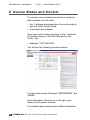
2 Device Status and Control
To view the current status and control it using the
Web interface you will need:
• the IP address announced over the audio outputs
(see the Quick Install Guide)
• a standard web browser
Open your web browser and type in the IP address
of the Barix device in the URL field and hit the
“Enter” key.
• Example: “192.168.0.229”
You will see the following window content:
The top frame shows the logos “INSTREAMER” and
“BARIX”.
Help information will show up in the right, grey
frame of the browser window.
The middle frame shows current status information
14 /63 BARIX AG | 28. Jan. 2014 | Device Status and Control
User Manual “Instreamer“ - V4.03
- 24th October 2013
and permits the control of the streaming status, the
simulation of the CTS input signal and the control of
the RTS output. For details see the section below.
2.1 Listen and Active Connections
The left frame has two selectable buttons.
Listen Online
Click the link to get the online Shoutcast stream of
the Instreamer (as M3U playlist) to play on your PC.
For proper operation make sure you configure MP3
encoding and send always.
Active Connections
Lists all active TCP and BRTP connections to the
Instreamer. All TCP connections are listed. That
includes web page access, Internet radios, raw TCP,
Shoutcast and Icecast connections. A TCP
connection is listed if and only if it's in the
"established" state.
2.2 Status and Control
The middle frame shows current status information
and permits the control of the streaming status, the
simulation of the CTS input signal and the control of
the RTS output. The page is refreshed automatically.
Streaming Mode
• "send always" - the device streams permanently
• "send on CTS" - the device streams if CTS input
on RS-232 interface is activated
BARIX AG | 28. Jan. 2014 | Device Status and Control | 15 /63
User Manual “Instreamer“ - V4.03 - 24th October 2013
• "send on I/O" - the device streams if the selected
digital input is activated
• "send on level" - the device streams if the input
audio peak reaches the configured level
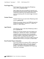
Audio Format
Displays the current streaming format and sampling
frequency.
Peak Left and Right
The numbers [in dB full-scale] and the graphical VU
meters show the peak values of the analog audio
inputs (line or microphone).
Max. value is 0 dB.
Input Source
Displays the audio input selected as source for
encoding.:
- grey box
= input available but not selected
- green box
= input selected
- crossed box = input not available on hardware
Status
Current status of the device:
IDLE:
grey box
The unit is not sending any stream, neither providing
data on listening ports (e.g. internet radio /xstream).
ENCODING:
green box
The unit is encoding audio, streaming to the
configured destinations and/or serving clients with
stream on the on configured network ports.
Start/Stop Buttons
In "send on..." modes the Instreamer functionality
can be controlled with the "start" and "stop"
buttons.
16 /63 BARIX AG | 28. Jan. 2014 | Device Status and Control
User Manual “Instreamer“ - V4.03
- 24th October 2013
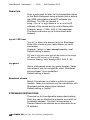
RS-232
Status of the hardware flow control signals of the
device's RS-232 iterface. The signals can be used
as a control input or output to control the device or
an attached equipment.
CTS in
Displays the status of the hardware CTS input
signal:
- grey box
= Inactive
- green box
= Active
Click the "set" button to emulate CTS being
activated.
Click the "clear" button to emulate CTS being
deactivated.
Note: the emulated input is not displayed on the
status page.
RTS out
Displays the status of the hardware RTS output
signal:
- grey box
= Inactive
- green box
= Active
Click the "set" button to activate the RTS signal.
Click the "clear" button to deactivate the RTS signal.
Contact inputs
Displays status of the eight digital contact closure
inputs (if available on the hardware):
- grey box
= idle
- green box
= Active
- crossed box = input not available on hardware
BARIX AG | 28. Jan. 2014 | Device Status and Control | 17 /63
User Manual “Instreamer“ - V4.03 - 24th October 2013
3 Device Configuration
You can adjust network settings, streaming
destinations, monitoring settings and more with the
Web interface. To enter the configuration mode you
will need:
• the IP address announced over the audio outputs
(see the Quick Install Guide)
• a standard web browser
Open your web browser and type in the IP address
of the Barix device in the URL field and hit the
“Enter” key.
• Example: “192.168.11.229”
You will see the following window content:
The top frame shows the logos “INSTREAMER” and
“BARIX”. Help information will show up in the right,
grey frame of the browser window.
Press the “Listen Online” button to open the radio
18 /63 BARIX AG | 28. Jan. 2014 | Device Configuration
User Manual “Instreamer“ - V4.03
- 24th October 2013
playlist file instreamer.m3u. Press the “Active
Connections” button to open a new window
showing the current active protocols and ports.
To obtain the configuration pages click the
CONFIGURATION button at the top of the page.
Note that the “screen shots” shown are for the
“Instreamer” HW. Other HW, for example, the
Exstreamer series, may have additional options to
support the enhanced features. In which case more
selection options are shown on the device`s Web
page.
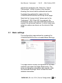
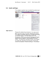
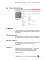
3.1 Basic settings
The configuration page entered by pressing the
CONFIGURATION button is headed Basic Settings.
The page allows the easy configuration of the most
common use case of a single stream entry. The
same configuration parameters also appear under
the Advanced Settings. Refer to these for more
detailed information.
BARIX AG | 28. Jan. 2014 | Device Configuration | 19 /63
User Manual “Instreamer“ - V4.03 - 24th October 2013
Input Source
Choose the desired Audio input source. Line mono
and MIC inputs are mono, the other settings are
stereo.
Default setting is "Line stereo".
Audio Format
Select encoding (data) format and sampling
frequency. The formats are: MPEG, PCM
(uncompressed digital audio), uLaw (G.711), aLaw
(G.711).
Default setting is "MPEG2 / 22.5 kHz".
Streaming Mode
"send always" will stream always
"send on CTS" will stream depending on the state of
the CTS input.
"send on Level" will stream if the incoming audio
signal is above the configured trigger level. The
default level is -24dB.
For send on CTS or send on Level, streaming can
also be controlled via the SEND and STOP buttons
on the HOME page.
Default setting is "send on CTS".
STREAMING DESTINATION - Conn. type
Choose the type of connection.
Note: only selected types are listed. Please see
advanced settings for a complete list of options.
•
•
•
"not used" for an unused destination
"RTP" for Real Time Protocol. Use an IP
address 0.0.0.0 to send to the network
broadcast address.
"BRTP" for the Barix extended RTP
protocol. The IP address is ignored. An
external device contacts this Instreamer on
the given port and statelessly registers to
receive the RTP stream. Up to 32 external
20 /63 BARIX AG | 28. Jan. 2014 | Device Configuration
User Manual “Instreamer“ - V4.03
•
- 24th October 2013
devices may register and up to 32 RTP
streams at 128kbit/s are supported.
"Raw UDP" for an outgoing UDP packet
stream.
Default settings is "RTP".
STREAMING DESTINATION - IP Address or Domain Name
If an active connection is required a Domain Name
or an IP address can be provided. An example of a
Domain Name is www.myserver.com. If an IP
address is provided, e.g. 192.168.0.34, then this is
used, otherwise the device attempts to obtain the IP
address from a Domain Name Server.
STREAMING DESTINATION - Port
Enter the port number for each destination (between
"0" and "65535"). "0" defines the following default
ports: Internet Radio "80", TCP "2020", UDP "3030".
For Shoutcast, enter the base port (the lower one,
the same as clients put into their radio players).
Default settings "0".
BARIX AG | 28. Jan. 2014 | Device Configuration | 21 /63
User Manual “Instreamer“ - V4.03 - 24th October 2013
3.2 Selecting Advanced Settings
To access the full set of configuration options, press
the Advanced Settings button.
A list of options is shown on the left together with
the Network settings. The required page can be
opened by selecting an option. Parameters can be
changed at will on any of the pages. It is only
necessary to press the Apply button once after all
changes have been made. This chapter explains
how to adjust the network settings of the Barix
device.
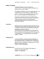
3.3 NETWORK SETTINGS
The following diagram shows the network settings
for automatic discovery (See IP address below).
However, we recommend that you set a Static IP
address so that the device does not have to get a
new IP address at power on or reboot.
22 /63 BARIX AG | 28. Jan. 2014 | Device Configuration
User Manual “Instreamer“ - V4.03
- 24th October 2013
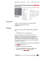
Use SonicIP®
If set to "yes", the device will announce its IP
address over the audio output.
Default: "yes"
IP Address
Enter the 4 values of the desired static IP address
e.g.:
• “192.168.0.12” for an internal LAN
Attention: Make sure that you enter a free IP
address. The device will check this and will not be
available until the device using the same IP is
disconnected or switched off. The command Ping
can be used to ensure that a specific IP address is
unused (i.e. No reply).
The automatic discovery functions are not executed
if a Static IP address is set.
The automatic options are as follow:
• “0.0.0.0” for automatic discovery (Discovery
order: BOOTP, DHCP, IPzator, AutoIP)
BARIX AG | 28. Jan. 2014 | Device Configuration | 23 /63
User Manual “Instreamer“ - V4.03 - 24th October 2013
For each function you want to disable add the value
from the table below:
•
•
•
•
“0.0.1.0” to disable AutoIP
“0.0.2.0” to disable DHCP
“0.0.4.0” to disable BOOTP
“0.0.8.0” to disable IPzator
Examples:
• “0.0.3.0” disables AutoIP and DHCP
• “0.0.11.0” disables all except BOOTP
Attention: “0.0.15.0” disables all discovery functions
which locks you out unless you reset the device to
factory defaults by pressing the reset button for
about 10 seconds.
Netmask
Enter the 4 values of the desired Netmask e.g.:
• “0.0.0.0” for a default Netmask depending on the
IP Address used
• “255.255.255.0” for a C class network
Note: Try first the Netmask your PC is set to or ask
your Network Administrator.
Gateway IP Address
A correct setting of the Gateway IP address is
needed to stream to the Internet or to destinations
outside your local network (LAN).
Enter the 4 values of the desired Gateway IP
address e.g.:
• "0.0.0.0" for no Gateway or automatic discovery
• "192.168.0.1" for a Gateway in a LAN
Note: If you have set the devices IP address to
automatic discovery and your server or router has
24 /63 BARIX AG | 28. Jan. 2014 | Device Configuration
User Manual “Instreamer“ - V4.03
- 24th October 2013
issued an IP address then most probably it also has
supplied a valid Gateway address, “0.0.0.0” will then
work fine.
If you have set a Static IP address then you will need
to configure a valid Gateway address manually. Try
first the same Gateway IP address your PC is set to.
If it doesn’t work then ask your Network
Administrator for a correct Gateway IP address.
Primary/Alternative DNS
In these fields you can provide DNS IP addresses
which are used to resolve URLs, e.g. www.radio.com
DHCP Host Name
From version VB3.17 a DHCP host name can be
configured for the device. If this field is left blank
then the device creates a DHCP name using part of
the Ethernet MAC address e.g.“CO1ED04” where
ED04 are the 2 least significant bytes of the MAC.
Web server port
Defines the port where the webserver of the Barix
Exstreamer can be reached. If set to "0" the default
HTTP port (80) is used. Default: "0".
Type of Service/DSCP
Type Of Service value used for RTP and UDP
streaming. DSCP (Differentiated Service Code Point)
supersedes the IP4 ToS value and uses the first 6
bits of the TOS field.
The following table illustrates the DSCP values:
BARIX AG | 28. Jan. 2014 | Device Configuration | 25 /63
User Manual “Instreamer“ - V4.03 - 24th October 2013
Check for DSCP services available in your network
to set this value. Valid values are 0-63.
Default value is 0.
26 /63 BARIX AG | 28. Jan. 2014 | Device Configuration
User Manual “Instreamer“ - V4.03
- 24th October 2013
3.4 Audio settings
This chapter explains how to adjust the audio input
and output settings of the Barix device.
Input source
Choose the desired input source. Line mono and
MIC input are mono, the other settings are stereo.
The options available depend on the HW according
to the table below. The Exstreamer 500 and
Exstreamer 1000 have external Analogue to Digital
circuitry which support input speeds of 32 and
48kHz. The selection provides a better input signal
to noise ratio, however the A/D gain is fixed and
cannot be adjusted. Default setting is "Line stereo".
BARIX AG | 28. Jan. 2014 | Device Configuration | 27 /63
User Manual “Instreamer“ - V4.03 - 24th October 2013
Instreamer
Ex 500
Ex 1000
Line Mono
Line Mono
Line Mono
Line Stereo
Line Stereo Line Stereo
Ann
100/200
Ann 1000 Ann 155
Line Mono Line Mono
-
-
Line Stereo
-
-
-
-
MIC
MIC
MIC
SPDIF optical
-
AES-EBU
-
-
-
SPDIF coaxial
(MPEG input)
Line Ext
ADC
Line Ext ADC
-
-
-
Audio Format
Select encoding (data) format and sampling
frequency. The formats are: MPEG, PCM
(uncompressed digital audio), uLaw (G.711), aLaw
(G.711) . In case of S/PDIF audio input, MPEG1 is
used and the sampling frequency is auto detected.
Default setting is "MPEG2 / 22.5 kHz".
The bit rate used for 8 and 24kHz G.711 and PCM is
displayed in kbit/sec. in the table below.
Encoding / Sampling
freq.
8 kHz
24 kHz
G.711 8bit (uLaw or aLaw)
64
192
PCM 16bit
128
384
For MP3 average bit rates see Encoding Quality
below.
MPEG bitrate mode
Select between VBR (variable bitrate) and CBR
(constant bitrate) MPEG formats.
In CBR mode it is recommended to set the MP3 Bit
Reservoir to "use".
28 /63 BARIX AG | 28. Jan. 2014 | Device Configuration
User Manual “Instreamer“ - V4.03
- 24th October 2013
Warning: For potentially “lossy” transmission types,
typically RTP, use VBR where ever possible.
Note: For devices (e.g. Instreamer 100) with an
IPAM type of “generic” only VBR is supported.
Default: "VBR".
MPEG CBR bitrate
If MPEG CBR encoding is selected the audio
compression level (and consequently the audio
quality) is selected by the "bitrate" field. Select the
audio bit rate in kilobits per second.
Please note that depending on the sampling rate not
all bitrates are available.
Default: "128kbps"
Encoding Quality
If MPEG VBR encoding is selected the audio
compression level (and consequently the audio
quality) is selected by this parameter. Choose
between "0 lowest" and "7 highest" in steps of 1.
The encoder quality table below shows the average
bit rate in kilobits per second for the quality settings
and sampling frequencies in kHz using mono input
with MS-Stereo encoding disabled.
Encod./Quality
0
1
2
3
4
5
6
7
MPEG1 48kHz
72
76
80
88
96
112 144 160
MPEG1 44.1kHz
65
68
73
80
90
105 125 140
MPEG1 32kHz
52
56
64
72
80
96
112 136
MPEG2 24kHz
38
44
48
52
60
80
96 112
MPEG2 22.05kHz
35
38
40
45
50
60
75
90
MPEG2 16kHz
28
30
34
40
44
48
56
64
The encoder quality table below shows the average
bit rate in kbit/s (kilobits per second) for the quality
settings and sampling frequencies in kHz using
BARIX AG | 28. Jan. 2014 | Device Configuration | 29 /63
User Manual “Instreamer“ - V4.03 - 24th October 2013
stereo inputs.
Encod./Quality
0
1
2
3
MPEG1 48kHz
88
96
104 120 144 160 176 192
MPEG2 16kHz
35
38
44
48
4
56
5
64
6
80
7
96
The above table shows only the average bit rates for
16 kHz and for 48 kHz. As the “stereo” adds about
20 to 30 percent when compared to “mono” other
sampling frequencies can be calculated using the
previous “mono” table.
Advanced Encoder Settings
The following settings are for advanced users only.
Microphone gain (Annuncicom series only)
Choose the desired gain ("21" - "43.5" dB) for the
microphone.
Default setting is "21" dB.
A/D amplifier gain
Choose the desired gain (“-3” up to “19.5” dB) for
the line input A/D amplifier.
Default setting is "-3" dB.
MP3 Bit Reservoir
The Bitreservoir is used to compensate the
differences between the predefined frame sizes. If
set to "use", the encoder will use the bit reservoir.
Note: if you use RTP streaming, to avoid audio
artefacts due to lost packets, set Bit Reservoir
to "keep empty" and use VBR.
Default setting is "use".
30 /63 BARIX AG | 28. Jan. 2014 | Device Configuration
User Manual “Instreamer“ - V4.03
- 24th October 2013
Advanced MP3 Encoder Settings
The following features are only available on IPAM
Type: generic
MP3 Frame CRC
If set to “enable”, the encoder will include the CRC16 in each MP3 frame.
MP3 Channel Mode Extension
“Enable” or “disable” the MS-Stereo encoding (for
stereo only). When set to “disable MS-Stereo
encoding” only mono will be encoded and therefore
the bandwidth used is minimized.
MP3 Copyright Protection
“Enable” or “disable” the copyright protection bit in
the MP3 stream.
MP3 Stream Type
Select between a “copy” or an “original” in order to
set the appropriate bit in the MP3 stream.
MP3 Emphasis
Select emphasis “none”, “50/15 us” or “CCITT
J.17”.
BARIX AG | 28. Jan. 2014 | Device Configuration | 31 /63
User Manual “Instreamer“ - V4.03 - 24th October 2013
3.5 Streaming settings
These settings adjust the streaming mode,
parameters and destinations.
32 /63 BARIX AG | 28. Jan. 2014 | Device Configuration
User Manual “Instreamer“ - V4.03
- 24th October 2013
Streaming mode
Streaming is started depending on the selected
operating mode:
• send always will stream always
• send on CTS will stream if the SEND button
(command) is pressed or CTS (Pin 8 Serial
connector) is connected to a positive supply
(9VDC, Pin 4 Serial connector)
• send on Level will stream if the incoming
analogue audio signal is above the Trigger level
(see section below). This feature is not available
for digital inputs.
• send on I/O (only available on devices with GPI)
will stream audio depending upon the state of the
GPI configured as the Control GPI
• For send on CTS, send on I/O or send on Level,
streaming can also be controlled via the SEND
and STOP buttons on the HOME page.
Default setting is "send on CTS".
Trigger level
The Trigger level is only used when Streaming mode
is set to send on Level.
Select a value between 0 and 32767.
Open the Device status page and look for the Input
peak value to get a hint for the trigger value. This
page refreshes itself every few seconds.
Pre Trigger Start
PreTrigger Start is only used when Streaming mode
is set to send on Level.
PreTrigger Start can be adjusted to prevent a cut off
when audio should be sent earlier than detected. It
defines the amount of time that will be streamed
before the actual trigger occurred.
BARIX AG | 28. Jan. 2014 | Device Configuration | 33 /63
User Manual “Instreamer“ - V4.03 - 24th October 2013
Post Trigger Play
Post Trigger Play is only used when Streaming
mode is set to send on Level.
Post Trigger Play can be adjusted to prevent a cut
off when audio should be sent longer than detected.
It defines the amount of time that the device will
continue streaming after the actual trigger has been
cleared.
Contact Closure
Contact Closure is only used when Streaming mode
is set to send on I/O.
Defines the contact closure input (GPI) that controls
the device streaming in "send on I/O". Select the
polarity in "Input Polarity".
Input Polarity
Input Polarity is only used when Streaming mode is
set to send on I/O.
Selects the contact closure event that triggers the
streaming in "send on I/O" mode. "active closed"
causes the device to stream when the selected
contact is closed. "active open" causes the device
to stream when the selected contact is open.
Used to select whether the device streams when the
selected control GPI is in the open or closed state.
Send Contact Closure Information
The current state of the device's GPI is inserted into
RTP and Shoutcast streams. (This also applies to
the BRTP connection type which uses an RTP
stream). This feature is compatible with Streaming
Client v02.10 and later.
34 /63 BARIX AG | 28. Jan. 2014 | Device Configuration
User Manual “Instreamer“ - V4.03
- 24th October 2013
Buffer Underrun Mode (TCP)
The Buffer Underrun Mode (TCP) defines the action
if a TCP stream is slower than the real stream from
the encoder. In this case the output streaming buffer
underruns and cannot hold older data any more. The
device can then “disconnect” the TCP connection or
it can ”skip” the stream directly to the encoder
stream without disconnecting TCP.
Streaming Packet Strategy
The Streaming Strategy defines how a packet is
build and sent. On “lowest latency” the encoded
data will be sent directly after the encoding. On
“optimal package” the packet will be filled up before
sending.
UDP Tx Source Port
This setting is only used with a custom software
application. Enter the used source port number for a
UDP stream (between 0 and 65535). When set to 0
the source port is set to the same port as selected in
the destination port (in section Stream to). If
destination is set to “origin source” the UDP
Receiver Port is used.
SHOUTCAST/ICECAST SETTINGS
The following parameters are used for Shoutcast
and Icecast
Own Name
You can enter the name of the Barix Instreamer
here. This is returned by the DISCOVER command
(see technical documentation).
Default setting is "Instreamer". Used also as
Shoutcast station name (icy-name).
BARIX AG | 28. Jan. 2014 | Device Configuration | 35 /63
User Manual “Instreamer“ - V4.03 - 24th October 2013
Radio Path
Enter a radio path to listen to the transmitted stream
of this Barix Instreamer using a device that is able to
play MP3 radio stations (also PC software like
WinAmp). The URL to connect is
http://x.x.x.x/p where x.x.x.x is the IP
address of this device and /p is this Radio path.
Example: http://192.168.0.24/xstream
The device can serve up to 6 concurrent radio
streams
icy-url / SIP user
“icy-url” is taken into account only for Shoutcast.
Enter URL of web of your radio station (up to 60
characters).
Example: ”http://www.exampleradio.com“
Default setting is empty.
SIP user is the user name that will be called on the target
SIP device (SIP server or SIP phone)
Example: ”betty“ calls ”[email protected]“
icy-genre
Genre of streamed music (icy-genre header). Taken
into account only for connection when “Shoutcast
source stream” type is selected.
Default setting is empty
Shoutcast stream
Select if the stream is private or public (icy-public
header). Taken into account only for connection with
Shoutcast source stream type selected.
Default setting is “public”.
STREAMING DESTINATIONS
There are up to 8 configurable stream destinations.
Each one can be directed to a device, or a multi- or
broadcast address. The first 4 entries allow a
Domain Name to be defined as an alternative to an
IP address.
36 /63 BARIX AG | 28. Jan. 2014 | Device Configuration
User Manual “Instreamer“ - V4.03
- 24th October 2013
Conn. type
The connection types are described in the following
sections. The following table summarizes which
connection types can act as passive listeners and
which as active senders.
Passive
(listener)
Internet
Radio
-
Active
(Sender)
-
RTP -
BRTP SIP
-
Raw
TCP
-
Shoutcast
Raw
UDP
Raw
TCP
Icecast
source
Shoutcast
Connection type - not used entry
Set the connection type to “not used” to disable an
entry. The IP and Port can be left as is as they are
as they do not matter on a disabled entry.
Connection type - Internet Radio entry
Set the connection type to “Internet Radio” radio
server for a single client (default). The IP “0.0.0.0”
will act as a TCP listener (HTTP) waiting for a
connection on the port selected under “Port#”
(0=80). Users must provide the Radio Path string
(see Radio Path above) or as an alternative one of the
following play list formats:
• instreamer.m3u
• instreamer.asx
• instreamer.pls
• instreamer.ram
The m3u and asx files have an alternative radio path
defined which can be modified by providing an IP
address and optional port number in entry #8 of the
Streaming table. If the port entry is left as 0 then the
normal HTTP port 80 is used.
BARIX AG | 28. Jan. 2014 | Device Configuration | 37 /63
User Manual “Instreamer“ - V4.03 - 24th October 2013
Other configurations are also possible since in
general entry #7 of the Streaming table modifies the
first entry in the m3u and asx files and entry #8
modifies the second file entry.
Limitation: Although eight entries can be configured
only six concurrent radio servers are supported.
Connection type - RTP entry
Set the connection type to “RTP” (Real Time
Protocol) for an RTP destination. The IP “0.0.0.0”
will broadcast (UDP) on the subnet (e.g.
"192.168.0.255") on the port selected under “Port#”
(e.g. 4040), enter an IP for a UDP unicast destination
(e.g. “192.168.0.11).
Connection type - BRTP entry
Set the connection type in the first entry to “BRTP”
(Barix Real Time Protocol) for a BRTP server (up to
32 clients). The IP “0.0.0.0” will act as a BRTP
listener (UDP) waiting for BRTP clients requesting a
stream on the port selected under “Port#” (e.g. 80).
Up to 32 external devices may register and up to 32
RTP streams at 128kbit/s are supported. This
maximum rate is approximately provided by the
MP3 setting: Encoding+Frequency MPEG1/48kHz
and Encoding quality 5.
Connection type - SIP entry
SIP is only available with the first entry.
Set the connection type to “SIP” for an asterisk SIP
server destination. Enter the IP of the SIP server. SIP
works only when either “u-Law 8kHz” or “a-Law
8kHz” encoding is selected. Enter the UDP port of
the SIP server under “Port#” (Port 0=5060).
See also section icy-url / SIP user further above.
38 /63 BARIX AG | 28. Jan. 2014 | Device Configuration
User Manual “Instreamer“ - V4.03
- 24th October 2013
Connection type - Raw UDP entry
Set the connection type to “Raw UDP” for an UDP
destination. The IP “0.0.0.0” will broadcast (UDP) on
the subnet (e.g. "192.168.0.255") on the port
selected under “Port#” (0=3030), enter an IP for a
UDP unicast destination (e.g. “192.168.0.11).
Connection type - Raw TCP entry
Set the connection type to “Raw TCP” for a single
TCP client. The IP “0.0.0.0” will act as a TCP listener
waiting for a connection on the port selected under
“Port#” (0=2020).
Connection type - Icecast source entry
Set the connection type to Icecast source to
connect (TCP) to a single Icecast server. Enter IP
and port of the Icecast server for the device to act
as an Icecast source. When authentication is
needed please read also section Icecast/Shoutcast
(Security settings).
Connection type - Shoutcast source entry
Set the connection type to “Shoutcast source” to
connect (TCP) to a single Shoutcast server. Enter IP
and port of the Shoutcast server for the device to
act as a Shoutcast source. When authentication is
needed please read also section Icecast/Shoutcast
(Security settings).
The IP “0.0.0.0” will let the Instreamer act as a
Shoutcast server itself waiting for a connection on
the port selected under “Port#”. The function is then
limited to a single client (a media player like
Winamp) and only one entry is allowed to be set to
Shoutcast server (IP 0.0.0.0).
BARIX AG | 28. Jan. 2014 | Device Configuration | 39 /63
User Manual “Instreamer“ - V4.03 - 24th October 2013
IP Address or Domain Name
If an active connection is required within the first 4
entries, a Domain Name or an IP address can be
provided. An example of a Domain Name is
www.myserver.com. If an IP address is provided,
e.g. 192.168.0.34, then this is used, otherwise the
device attempts to obtain the IP address from a
Domain Name Server.
Default setting:"not used".
IP # # # #
Enter 4 values of the destination IP address e.g.:
• "0.0.0.0" with connection type set to UDP. The
stream will be broadcast to the local broadcast
address e.g. to "192.168.0.255".
• "0.0.0.0" with connection type set to TCP and a
Port number defined. A TCP listener waiting for a
connection from a streaming device.
• "0.0.0.0" with connection type set to Internet
radio or Shoutcast. This listens to a TCP HTTP
request.
• "0.0.0.0" for unused destinations
• "192.168.0.34" for a directed connection
• "192.168.0.255" for a broadcast
Default settings are "Internet Radio 0.0.0.0:0".
Port #
Enter the port number for each destination (between
0 and 65535). If this port is set to 0 then the default
ports are used (Internet Radio 80, TCP 2020, UDP
3030). For Shoutcast, enter the base port (the lower
one, the same as clients put into their radio players).
40 /63 BARIX AG | 28. Jan. 2014 | Device Configuration
User Manual “Instreamer“ - V4.03
- 24th October 2013
3.6 I/O and Serial Settings
I/O SETTINGS
Configure which of the commands below should be
issued when the CTS signal on the serial connector
is activated
CTS close command
Configures which command should be issued when
the CTS signal on the serial connector is activated
CTS open command
Configures which command should be issued when
the CTS signal on the serial connector is
deactivated
Commands
Commands can be joined using the “&” character
and will be executed sequentially. For further
commands refer to the “Instreamer technical
documentation”.
BARIX AG | 28. Jan. 2014 | Device Configuration | 41 /63
User Manual “Instreamer“ - V4.03 - 24th October 2013
SENDING MODE
c=84 : Deactivate the sending mode, if not send
always
c=91 : Activate the sending mode
SERIAL
c=89 : Simulate the CTS Signal being activated
c=90 : Simulate the CTS Signal being deactivated
c=60 : Activate the RTS Signal
c=61 : Deactivate the RTS Signal
For further commands refer to the technical
documentation available on www.barix.com.
SERIAL SETTINGS
When the serial port is not being used as a Serial
Gateway it defaults to a command interface.
Baud rate
Select the serial transmission speed ("300" to
"115200" Baud).
Default: "9600"
Data bits
Select "7" or "8" data bits.
Default: "8"
Parity
Select "no", "even" or "odd" parity.
Default: "no
Stop bits
Select "1" or "2" stop bits.
Default: "1"
Flow control
Select the type of flow control: "none", "Software
(XON/XOFF)" or "Hardware (RTS/CTS)".
Default: "none"
42 /63 BARIX AG | 28. Jan. 2014 | Device Configuration
User Manual “Instreamer“ - V4.03
- 24th October 2013
SERIAL GATEWAY
The Serial Gateway function allows the
establishment of a serial connection between two
devices over a LAN or WAN.
To enable the Gateway function "Destination IP" and
"Destination port" are set at the initiator (active)
device. At the receiver (passive) device the “Local
port” is set to the partner's “Destination port”.
On power up the active device connects to the
passive device and tries to reconnect automatically
if the connection is lost. If the connection is
successful serial data can be passed end-to-end
across the network.
Local port
Defines the port on which the serial interface can be
accessed for serial gateway applications. Only when
"Local port" is set to "0" can the serial interface be
used as a command interface.
If Destination IP is nonzero and the "Local port" is
set to a value then this will be the source port of the
TCP connection. If the Destination IP is nonzero and
"Local port" is "0" a random source port is used.
Default: "12303".
Destination IP
To have this Barix Instreamer actively establish a
serial gateway select the destination IP address of
the device with which serial data will be exchanged.
Select "0.0.0.0" to disable the gateway and use the
serial interface locally only.
Default: "0.0.0.0" (disabled).
Destination port
Defines the port for the active serial gateway
function (see destination IP).
Default: "0" (disabled)
BARIX AG | 28. Jan. 2014 | Device Configuration | 43 /63
User Manual “Instreamer“ - V4.03 - 24th October 2013
Note:
When the Serial Gateway function is activated the
serial port on both devices cannot be used as a
command interface.
44 /63 BARIX AG | 28. Jan. 2014 | Device Configuration
User Manual “Instreamer“ - V4.03
- 24th October 2013
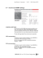
3.7 Control and SNMP settings
CONTROL SETTINGS
As well as the CGI WEB commands available over
http, the Instreamer offers two dedicated remote
control interfaces: UDP and TCP. See the Technical
Documentation for more details about the protocol.
These settings adjust the control port properties.
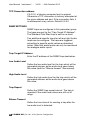
UDP command port
Configure a port number between 1 and 65535 to
enable the UDP command interface.
Enter 0 to disable the UDP command interface.
Default: "12301"
TCP command port
Configure a port number between 1 and 65535 to
enable the TCP command interface.
Enter 0 to disable the TCP command interface.
Default: "12302"
BARIX AG | 28. Jan. 2014 | Device Configuration | 45 /63
User Manual “Instreamer“ - V4.03 - 24th October 2013
TCP Connection address
If 0.0.0.0, a listening command port is opened.
Otherwise a TCP connection is actively attempted at
the given address and port. If the connection fails, it
is reattempted every minute. Default:0.0.0.0
SNMP SETTINGS
SNMP traps are configured in this parameter group.
The traps are sent to the “Trap Target IP Address”.
The Standard Cold Start trap is sent on re-boot.
Two additional specific traps for left and right Audio
levels can be configure. The traps are triggered
according to specific audio values as described
below. Note that audio levels can only be monitored
for analogue audio inputs.
Trap Target IP Address
Enter the IP address of the SNMP trap destination.
Low Audio Level
Define the low audio level for the trap which will be
generated as soon as the audio level goes below
this value (and the “Silence timeout” has expired).
High Audio Level
Define the high audio level for the trap which will be
generated as soon as the audio level goes above
this value.
Trap Repeat
Define the SNMP trap repeat interval. The trap is
repeated if the audio level values are still out of
range.
Silence Timeout
Define the time interval for sending a trap after the
low audio level is detected.
46 /63 BARIX AG | 28. Jan. 2014 | Device Configuration
User Manual “Instreamer“ - V4.03
- 24th October 2013
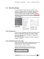
3.8 Security settings
These settings are used to secure access to the
device on different levels. The status is shown next
to each password ("set" or "not set"). Access is
open for levels without a password (default setting).
Save Configuration
Enter up to 24 characters to secure the saving of the
device configuration (Clicking the "Apply" button).
Without a valid password the device configuration
can not be saved!
Enter 25 characters to erase the current password.
Default: "not set"
Save configuration password usage
When the password is set the user has to type in the
password in the "Save Config Password field"
before hitting the "Apply" button.
Without a valid password a warning will be
displayed and the changes will not be saved.
BARIX AG | 28. Jan. 2014 | Device Configuration | 47 /63
User Manual “Instreamer“ - V4.03 - 24th October 2013
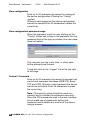
View configuration
Enter up to 24 characters to secure the viewing of
the device configuration (Clicking the “Config”
button).
Without a valid password the device configuration
cannot be viewed! Enter 25 characters to erase the
current key.
View configuration password usage
When the password is set the user clicking on the
“Config” button has to type in the password into the
password field of the pop up window (the user name
does not matter).
Only one user can log in at a time, in which case
further attempts are refused.
To log out click on the “Logout” link at the top right
of the page.
Control / Command
Enter up to 24 characters to secure the access to all
control and command interfaces (WEB/CGI, Serial,
TCP and UDP). Without a valid password the device
cannot be controlled. Enter 25 characters to erase
the current key.
Note : This security option should be used very
carefully and is intended for advanced users only.
Since the CGI commands used in the web interface
do not make use of passwords, setting this
password would disable any control of the device
using a browser.
48 /63 BARIX AG | 28. Jan. 2014 | Device Configuration
User Manual “Instreamer“ - V4.03
- 24th October 2013
User Password
Enter up to 24 characters to secure the access to
customized web pages. Intended for advanced
users only, for details see the Technical
Documentation. Without a valid password these
user web pages cannot be viewed.
Enter 25 characters to erase the current password.
Default: "not set"
Icecast/Shoutcast
Enter up to 24 characters. This is the password the
device uses when accessing Icecast or Shoutcast
server and acting as a source. Applies only for
"Icecast source" or "Shoutcast source" streaming
option selected. When 25 or more characters
entered, the password is erased.
Listening
Choose which level is used for preventing
unauthorized listeners from listening to the
Instreamer in Internet Radio mode, or "not
protected" for access for all.
SNMP Community RWrite
Choose a password for the Read and Write
Community, or "not protected" to ignore both the
read and write communities or "no write access"
SNMP Community Read
Choose a password for the Read Community, or
"not protected" to ignore the read community or "no
access"
Note that the Community RWrite setting takes
priority. This means that if the Community RWrite is
set to not protected, Community Read is ignored.
BARIX AG | 28. Jan. 2014 | Device Configuration | 49 /63
User Manual “Instreamer“ - V4.03 - 24th October 2013
3.9 Additional Features
From V3.17 two xml files are added to provide a
LiveFeed Service for Cisco's Call Manager.
For the Call Manager settings please refer to the
relevant Cisco documentation. The Service URL to
configure is:
http://<Instreamer IP address>/livefeed.xml.
So in the example below this would be:
http://192.168.11.171/livefeed.xml.
livefeed.xml
To use this feature configure the Instreamer 5th
Streaming Destination for RTP <IP address> <port
number>.
The IP address and port from the 5th Streaming
Destination and the Instreamer device's own IP
address are dynamically inserted into the
livefeed.xml file.
An example of the resulting XML is as follows:
<CiscoIPPhoneExecute>
<ExecuteItem URL="RTPMRx:239.1.1.25:20480"/>
<ExecuteItem URL="http://192.168.11.170/listen.xml"/>
</CiscoIPPhoneExecute>
listen.xml
The Instreamer Own Name is copied to the Title in
the listen.xml file as in the following resulting XML
example:
<CiscoIPPhoneText>
<Title>Instreamer_1</Title>
<Prompt>Press Exit to stop listening</Prompt>
<Text>Live audio streaming...</Text>
<SoftKeyItem><Name>Exit</Name>
<URL>SoftKey:Exit</URL>
<Position>1</Position>
<URLDown>RTPRx:Stop</URLDown>
</SoftKeyItem>
</CiscoIPPhoneText>
50 /63 BARIX AG | 28. Jan. 2014 | Device Configuration
User Manual “Instreamer“ - V4.03
- 24th October 2013
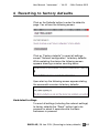
4 Reverting to factory defaults
Click on the Defaults button to enter the defaults
page. You will see the following screen:
Click on “Factory defaults” to revert all settings
except “Network configuration” to factory defaults.
While restarting the device the following screen
appears showing a number counting down:
Upon start up the following screen appears stating
the successful reversion to factory defaults:
Hard default settings
To revert all settings (including the network settings)
to factory defaults the “Reset” button has to be
pressed for about 5 seconds while the Barix
Instreamer is powered.
BARIX AG | 28. Jan. 2014 | Reverting to factory defaults | 51 /63
User Manual “Instreamer“ - V4.03 - 24th October 2013
Note: You can use this method if a connection to
the Barix Instreamer cannot be established.
This can happen if you once have set a Static IP
address, switched off “SonicIP” and then forgotten
the IP address.
The Hard default settings sets the IP Address to
automatic discovery (0.0.0.0) and enables SonicIP.
We also recommend downloading and installing the
Barix Binary Discovery Tool from:
http://www.barix.com/downloads/downloadsfirmware/software-tools/
If the tool is installed on a PC, a target device, on
the same subnet, can be discovered even if the IP
address is invalid. The IP address can be corrected
and the device put back into service.
If this fails we recommend to download the
“Instreamer Rescue Kit” from www.barix.com.
Unzip the Kit and read “readme1st.txt” for
instructions.
This Rescue Kit reloads the entire firmware, resets
the device to factory default settings using the
supplied serial cable and a PC running Windows
XP/2000/NT, Linux or MAC.
52 /63 BARIX AG | 28. Jan. 2014 | Reverting to factory defaults
User Manual “Instreamer“ - V4.03
- 24th October 2013
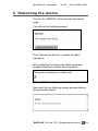
5 Rebooting the device
Click on the REBOOT button to enter the reboot
page.
You will see the following screen:
Click “Reboot the device” to restart the Barix
Instreamer.
While restarting the device the following screen
appears showing a number counting down:
Upon start up the following screen appears stating
the successful restart:
BARIX AG | 28. Jan. 2014 | Rebooting the device | 53 /63
User Manual “Instreamer“ - V4.03 - 24th October 2013
6 Updating the device
Barix preloads the Instreamer devices with firmware
which is current at the day of production.
Barix constantly enhances the capabilities and
functions and recommends to keep the firmware on
the Barix Instreamer up-to-date.
Barix recommends the use of the “Serial Rescue”
method to update the firmware.
For the alternative method “Web Update” the
“Web server port” has to be set to “0” or “80” to
work properly (0 will set the default port “80”).
If the web update is interrupted during the process
(power or network loss) the device might become
unreachable. In that case the “Serial Rescue”
procedure is the only remedy. Please keep that in
mind when planning a remote update.
6.1 Downloading the latest firmware
To download the latest “Instreamer” firmware
version please visit www.barix.com.
• On the menu at the top click on Downloads
• Under Firmware Download select “Instreamer
Standard Firmware”.
• Select the Instreamer FW Kit to download it.
• Save the ZIP file and unpack it to a local drive.
Read the "_readme1st.txt" file for detailed
instructions.
54 /63 BARIX AG | 28. Jan. 2014 | Updating the device
User Manual “Instreamer“ - V4.03
- 24th October 2013
6.2 Serial Rescue
The “Serial Rescue” procedure loads the entire
firmware and resets the device to factory default
settings (current configuration is overwritten).
It is therefore helpful to note the current setting.
Printing out the “status” page is the quickest way as
the page contains all configuration parameters.
Open your web browser and type in the IP address
of the Barix device in the URL field and hit the
“Enter” key. Press the STATUS button.
To apply the Rescue using a serial cross cable and a
PC running Windows, Linux or a MAC follow the
steps in the “_readme1st.txt” carefully as there are a
number of different options available.
Allow approximately 2 minutes to complete the
“Serial Rescue” procedure. After a successful
rescue the device is ready for configuration
according to your needs
(see chapter 3 Device Configuration).
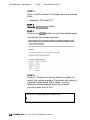
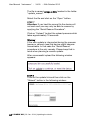
6.3 Web Update
To apply the “Web Update” procedure you will need
a standard web browser and the IP address of the
device (announced by the SonicIP feature).
Make sure that the “Web server port” is set to “80”
before starting the procedure.
The upload itself will take about 10 seconds.
STEP 1
Open your web browser
BARIX AG | 28. Jan. 2014 | Updating the device | 55 /63
User Manual “Instreamer“ - V4.03 - 24th October 2013
STEP 2
Type in the IP address of the Barix device and press
Enter:
• Example: “192.168.0.12”
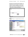
STEP 3
Click the
STEP 4
Click on the
button.
button to enter the update page.
You will see the following screen:
STEP 5
Click on “Please click here to start the update” to
launch the update process. The device will restart in
a special mode called “Boot loader” and the
following screen appears showing a number
counting down from 4 to 0.
56 /63 BARIX AG | 28. Jan. 2014 | Updating the device
User Manual “Instreamer“ - V4.03
- 24th October 2013
Upon start up the following screen appears. The
Bootloader version and date will most likely be
different. The other information provides numeric
values for HW type and IPAM type, some HW
register data which can be ignored and gives the
total number of uploaded Flash pages:
STEP 6
Click on "Browse..." to select the file you want to
update.
BARIX AG | 28. Jan. 2014 | Updating the device | 57 /63
User Manual “Instreamer“ - V4.03 - 24th October 2013
The file is named compound.bin located in the folder
“update_rescue”.
Select the file and click on the “Open” button.
STEP 7
Attention: If you load the wrong file the device will
not work and you may only be able to recover by
applying the “Serial Rescue Procedure”.
Click on “Upload” to start the upload process which
takes approximately 10 seconds.
Warning:
If the web update is interrupted during the process
(power or network loss) the device might become
unreachable. In that case the “Serial Rescue”
procedure is the only remedy. Please keep that in
mind when planning a remote update.
After a successful upload the following window
appears:
STEP 8
Click on the update link and then click on the
"Reboot" button in the following window:
58 /63 BARIX AG | 28. Jan. 2014 | Updating the device
User Manual “Instreamer“ - V4.03
- 24th October 2013
The following screen appears:
STEP 9
After the device has rebooted click on the “here” link
to reload the main page.
The device is now ready for configuration according
to your needs (see chapter 3 Device Configuration).
Note: The “Web Update” procedure does not
change the current configuration. Barix
recommends nevertheless checking for correct
parameters in the configuration as well as to set
parameters for newly added features.
If you observe strange behavior after an update
Barix recommends resetting the configuration to
factory defaults by keeping the Reset button
pressed until the red LED starts blinking (approx. 10
seconds) and to start over with the configuration of
the device.
BARIX AG | 28. Jan. 2014 | Updating the device | 59 /63
User Manual “Instreamer“ - V4.03
- 24th October 2013
7 Dictionary
DHCP
Short for Dynamic Host Configuration Protocol, a
protocol used to assign an IP address to a device
connected to a Network.
IP
Short for Internet Protocol, the IP is an address of a
computer or other network device on a network
using IP or TCP/IP. Every device on an IP-based
network requires an IP address to identify its
location or address on the network. Example:
192.168.2.10
IPzator
Barix IPzator™ technology is designed for the
purpose that the Barix device can create its own IP
address according to the network structure in case
it can’t receive one from your network. If DHCP,
AUTOIP or BOOTP fail, IPzator will create an IP
address within the subnet and test it. If the address
works and is not being used by another device on
the network, it will give the address to the Barix
device.
MAC address
Abbreviation for Medium Access Control, a MAC is
a unique address number formatted in hexadecimal
format and given to each computer and/or network
device on a computer network. Because a MAC
address is a unique address a computer network
will not have the same MAC address assigned to
more than one computer or network device.
Example: A1:B2:C3:D4:E5:F6
Netmask
A number used to identify a sub network so that an
IP address can be shared on a LAN (Local Area
Network).
A mask is used to determine what subnet an IP
address belongs to. An IP address has two
components, the network address and the host
address. For example, consider the IP address
150.215.17.009. Assuming this is part of a Class B
network, the first two numbers (150.2) represent the
BARIX AG | 28. Jan. 2014 | Dictionary | 61 /63
User Manual “Instreamer“ - V4.03 - 24th October 2013
Class B network address, and the second two
numbers (.017.009) identify a particular host on this
network. The Netmask would then be 255.255.0.0 .
Ping
Ping is a basic Internet program that lets you verify
that a particular IP address exists and can accept
requests. Example: ping 192.168.2.10
SonicIP
Barix SonicIP ® technology is designed to vocally
announce the Barix devices current IP address. This
makes it easier and faster to obtain the necessary
network information. To make use of SonicIP plug in
the included earphone into RCA audio out, connect
the network and plug in the power supply. It will
announce the address over the earphones right after
power up.
Static IP
A Static IP is a fixed IP address that you assign
manually
to a device on the network. It remains valid until you
disable it.
Telnet
Telnet is a user command and an underlying TCP/IP
protocol for accessing remote computers. On the
Web, HTTP and FTP protocols allow you to request
specific files from remote computers, but not to
actually be logged on as a user of that computer.
With Telnet, you log on as a regular user with
whatever privileges you may have been granted to
the specific application and data on that computer.
Example: telnet 192.168.2.10
62 /63 BARIX AG | 28. Jan. 2014 | Dictionary
User Manual “Instreamer“ - V4.03
- 24th October 2013
8 Legal Information
© 2014 Barix AG, Zurich, Switzerland.
All rights reserved.
All information is subject to change without notice.
All mentioned trademarks belong to their respective
owners and are used for reference only.
Barix, Exstreamer, Instreamer, SonicIP and IPzator
are trademarks of Barix AG, Switzerland and are
registered in certain countries.
For information about our devices and the latest
version of this manual please visit www.barix.com.
Barix AG
Seefeldstrasse 303
8008 Zurich
SWITZERLAND
Phone: +41 43 433 22 11
Fax:
+41 44 274 28 49
Internet
web:
email:
support:
wiki:
www.barix.com
[email protected]
[email protected]
wiki.barix.com
BARIX AG | 28. Jan. 2014 | Legal Information | 63 /63