1
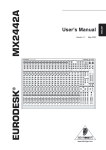
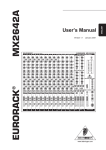
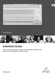
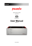
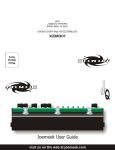
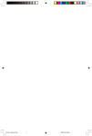
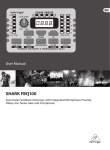
Gig 14
ORDERCODE D2205
Congratulations!
You have bought a great, innovative product from DAP Audio.
The DAP Audio GIG 14 brings excitement to any venue. Whether you want simple plug-&-play action or a
sophisticated show, this product provides the effect you need.
You can rely on DAP Audio, for more excellent audio products.
We design and manufacture professional audio equipment for the entertainment industry.
New products are being launched regularly. We work hard to keep you, our customer, satisfied.
For more information: [email protected]
You can get some of the best quality, best priced products on the market from DAP Audio.
So next time, turn to DAP Audio for more great audio equipment.
Always get the best -- with DAP Audio !
Thank you!
DAP Audio
DAP Audio GIG 14™ Product Guide
Warning..…...................................................................................…………………………………………..
Safety-instructions………………………………………………………………………………………….….
Operating Determinations…………………………………………………………………………………….
2
2
3
Description..…..............................................................................……….…………………………………
Features………………………………………………………………………………….………………….….
Overview ..…………………………………………………………………………………….………....…….
Frontside.….………………………………………………………………….……………….………....…….
Backside.………………………………………………………………………..…………….………....…….
4
4
4
5
6
Installation...............................................................................…...……………………………………..….
6
Set Up and Operation.....................................................................……..…………………………….…..
Mono Input Channel….............................................................................................…...........……......
Stereo Input Channel……........................................................................................................……....
Master Section.….................................................................................................................………....
Set Up ……………….............................................…………………………………...................…….....
7
7
8
9
10
Connection Cables..............................….......................................………..………….…….………….….
12
Maintenance………..............................….......................................………..………….…….………….….
13
Troubleshooting………..............................…................................………..………….…….………….…..
13
Block Diagram………..............................…................................………..………….…….………….……..
14
Product Specifications.................................................................……………….…….…………………..
15
1
WARNING
CAUTION!
Keep this system away from rain and moisture!
FOR YOUR OWN SAFETY, PLEASE READ THIS USER MANUAL CAREFULLY
BEFORE YOUR INITIAL START-UP!
SAFETY INSTRUCTIONS
Every person involved with the installation, operation and maintenance of this system has to:
be qualified
follow the instructions of this manual
CAUTION! Be careful with your operations.
With a dangerous voltage you can suffer
a dangerous electric shock when touching the wires!
Before you initial start-up, please make sure that there is no damage caused by transportation. Should there
be any, consult your dealer and do not use the system.
To maintain perfect condition and to ensure a safe operation, it is absolutely necessary for the user to follow
the safety instructions and warning notes written in this manual.
Please consider that damages caused by manual modifications to the system are not subject to warranty.
This system contains no user-serviceable parts. Refer servicing to qualified technicians only.
IMPORTANT:
The manufacturer will not accept liability for any resulting damages caused by the non-observance of
this manual or any unauthorized modification to the system.
•
•
•
•
•
•
•
•
•
•
•
•
•
•
Never let the power-cord come into contact with other cables! Handle the power-cord and all
connections with the mains with particular caution!
Never remove warning or informative labels from the unit.
Never use anything to cover the ground contact.
Never leave any cables lying around.
Do not insert objects into air vents.
Do not connect this system to a dimmerpack.
Do not switch the system on and off in short intervals, as this would reduce the system’s life.
Do not open the device and do not modify the device.
Do not drive the inputs with a signal level bigger, than required to drive the equipment to full output.
Do not plug Mics into the console (or stagebox) while Phantom Power is on. Also mute the monitor /
Pa system when turning Phantom Power on or off. Allow the system to adjust for a couple of
seconds, before setting the input gains.
Only use system indoor, avoid contact with water or other liquids.
Avoid flames and do not put close to flammable liquids or gases.
Always disconnect power from the mains, when system is not used. Only handle the power-cord by
the plug. Never pull out the plug by tugging the power-cord.
Always operate the unit with the AC ground wire connected to the electrical system ground.
2
•
•
•
•
•
•
•
•
•
•
•
•
•
•
•
•
Make sure you don’t use the wrong kind of cables or defective cables.
Make sure that the signals into the mixer are balanced, otherwise hum could be created.
Make sure you use DI boxes to balance unbalanced signals; All incoming signals should be clear.
Make sure that the available voltage is not higher than stated on the rear panel.
Make sure that the power-cord is never crimped or damaged. Check the system and the power-cord
from time to time.
In system setup, the amplifier's output power must be 50%-100% more than the loaded
loudspeakers rated power.
Please turn off the power switch, when changing the power cord or signal cable, or select the input
mode switch.
Extreme frequency boosts in connection with a high input signal level may lead to overdriving your
equipment. Should this occur, it is necessary to reduce the input signal level by using the INPUT
control.
To emphasize a frequency range, you don’t necessarily have to move its respective sliding control
upward; try lowering surrounding frequency ranges instead. This way, you avoid causing the next
piece of equipment in your sound path to overdrive. You also preserve valuable dynamic reserve
(“headroom”)
Avoid ground loops! Always be sure to connect the power amps and the mixing console to the same
electrical circuit to ensure the same phase!
If system is dropped or struck, disconnect mains power supply immediately. Have a qualified
engineer inspect for safety before operating.
If the system has been exposed to drastic temperature fluctuation (e.g. after transportation), do not
switch it on immediately. The arising condensation water might damage your system. Leave the
system switched off until it has reached room temperature.
If your Dap Audio device fails to work properly, discontinue use immediately. Pack the unit securely
(preferably in the original packing material), and return it to your Dap Audio dealer for service.
Repairs, servicing and electric connection must be carried out by a qualified technician.
For replacement use fuses of same type and rating only.
WARRANTY: Till one year after date of purchase.
OPERATING DETERMINATIONS
If this system is operated in any other way, than the one described in this manual, the product may suffer
damages and the warranty becomes void.
Any other operation may lead to dangers like short-circuit, burns, electric shock, etc.
You endanger your own safety and the safety of others!
Improper installation can cause serious damage to people and property !
3
Description of the device
Features
The GIG 14 is a mixer from Dap Audio.
• 6 Mono Input Channels with goldplated XLR connectors and balanced Line Inputs
• Ultra-low noise Mic pre-amps with +48 V Phantom Power
• 4 Stereo Input channels with balanced TRS jacks
• 2 additional multi-functional stereo Line inputs
• Extremely high headroom, offering a more dynamic range
• Balanced inputs for highest signal integrity
• Ultra musical 3-band EQ on all channels
• Peak LEDs and Low-Cut Filter on all Mono channels
• 2 AUX Sends per channel for external effects and monitoring
• Separate Master Mix, Control Room and Headphone outputs
• 2-Track inputs assignable to Master Mix Output
• Highly accurate 10 LEDs output level indicator
• High-quality Panasonic 60mm faders
• High-quality Panasonic sealed potentiometers
• Rugged design power supply ensures superior signal integrity
Overview
Fig. 1
4
Frontside
5
Backside
Installation
Remove all packing materials from the GIG 14. Check that all foam and plastic padding is removed.
Connect all cables.
Always disconnect from electric mains power supply before cleaning or servicing.
Damages caused by non-observance are not subject to warranty.
Mono Input Channels
Channels 1-6 are mono, with a choice of balanced Mic or Line inputs. While a large external power supply
ensures low noise and superior transient response at all times.
Stereo Input Channels
A further 8 Line inputs are configured as 4 stereo input channels. These are ideal for accepting outputs from
MIDI and other electronic instruments.
Channel Outputs
A high-quality true logarithmic 60mm fader feeds the Master Mix via the Channel Pan.
Aux Send
There are 2 Aux Send busses on the Gig 14, Aux1 is pre-fader, Aux 2 is a post-fader (the channel’s volume
control).
Stereo Line Inputs
There are 2 line-level Stereo Aux Returns at the top of the output section. They can be used to return stereo
effects or MIDI instruments, etc.
In addition, a stereo Tape input is provided, which may also be routed to the Master Mix, giving the Gig 14 a
total of 14 possible inputs during mixing. Channels 1-6 on the Gig 14, have overload LEDs, while the Master
Mix output has a 10-segment output level indicator. The L/R meters double up as mono PFL meters.
6
Set Up and Operation
Before plugging the unit in, always make sure that the power supply matches the product specification
voltage. Do not attempt to operate a 120V specification product on 230V power, or vice versa.
Mono Input Channel
Each mono channel comes with a XLR Mic input (1) and a balanced Line input on 1/4” jack (2). Phantom
powering is switch able from the panel (34). The trim circuit has a wide range from +10dB to +60dB,
obviating the need for mic / line switching. The crucial operating input level +4 dBu and –10 dBV are clearly
and accurately marked (4).
1. Input Level Setting
Mic Channel input level is determined by the TRIM control (4). In addition to Master Mix metering, a channel
PEAK LED (11) illuminates, when a channel is going into overload. These LEDs take their cue from postEQ. This level sampling is particularly useful when using extreme EQ settings.
2. Equalizer
All mono input channels are fitted with 3-band EQ, plus a switch able Low Cut filter for eliminating unwanted
subsonics. The upper (5) and lower (7) shelving controls have their frequencies fixed at 12 Khz and 80 Hz
respectively. The Mid range control (6) has a peaking response, with Q fixed at 2 octaves, frequency at 2.5
Khz. All 3 bands have up to 15 dB of cut and boost, with a centre detent for “OFF”. The Low Cut filter (3),
slope at 18 dB/oct., -3 dB at 75 Hz, is ideally suited for reducing floor rumble, breathing noises and popping,
woolly bottom end, etc.
3. Aux Sends
Both Aux Sends (8 & 9) are mono and post-EQ. Aux Send 1 (8) is set pre-fader, while Aux Send 2 (9) is
post-fader.
Aux 2 can be made pre-fader on mono channels Aux 2, see “Modification” for more details.
4. Fading and Panning
GAIN to the Master Mix bus is ultimately determined by the Channel Volume control (13).
Channel Pan (10) positions the output of the channel in the stereo field. Its constant-power design ensures
there are no level discrepancies whether a signal is hard-panned, centre-stage or somewhere in between.
Such pinpoint accuracy will be a revelation, if you have been working on consoles with lower quality circuits.
5. PFL
Depress switch (12). The MONO channel signal can be level to the switch (17), its origin of the
HEADPHONE / CONTROL ROOM.
7
STEREO INPUT CHANNEL
Each stereo channel comes with 2 balanced line level inputs on 1/4” TRS jacks (28), for left and right
signals. When only left input is connected, the channel operates in mono.
1. Input Gain Setting
The stereo Inputs are designed for any line level signal. Most line level sources such as MIDI instrument
and FX units will have their own output level control. Those that don’t, like CD-players, all have an output
level within the scope of the Gig 14. When the channel and master fader are set to unity gain the meters
should read between –4 dB and +7 dB. Remember that there is 15 dB Gain on both the channel as well as
the master fader.
2. Equalizer
There are no Low Cut filters on stereo channels, otherwise the EQ is in principle identical to that on MONO
channels (see Mono Input Channel: 2. Equalizer), except that the equalizer is stereo, of course!!
A stereo equalizer is generally preferable to using 2 mono equalizers when equalizing a stereo signal, as
often discrepancies between left and right settings occur.
3. Aux Sends
It is the same as for MONO Channels (see Mono Input Channel: 3. Aux Sends). Note that a mono sum is
taken from the stereo input.
4. Volume Control and Panning / Balancing
The only difference here to the Mono Channel described (see Mono Input Channel: 4. Fading and Panning)
is in the implementation of the Balance control (14). When a channel is run in stereo, this control determines
the relative balance of the Left and Right Channel signals being sent to the Left and Right Master Mix
busses. For example, with the Balance control turned fully clockwise, only the right portion of the channel’s
stereo signal will be added to the Master Mix.
If a Stereo Channel is run in mono (only the left input is connected), the Balance control acts as a pan in the
normal way.
8
MASTER SECTION
1. Aux Sends
Aux Sends are provided on unbalanced 6.3mm jacks (25). Please adjust the input level control of your
effects unit to match the output level of your DAP Audio, this be can done when typical signals are run
through the Gig 14 and the Aux Sends are set to center (0dB). If your effects unit does not have an input
gain and the effects levels seems too low, remember that every channel Aux Send has up to 15 dB gain,
which should be more than enough to drive any effects unit.
2. Stereo Aux-returns
There are 2 additional stereo inputs (Aux Returns 1 and 2) on your Gig 14. Their level can be adjusted with
(15) and (16). Aux Returns 1.2 is permanently assigned to the Master Mix. If you connect a jack only to the
left socket, the Aux Return 1.2 operates in mono. This enables you to provide a wet cue mix (signal with
effect i.e. reverb) for the headphones or foldback speakers.
Note: Sometimes you want to narrow the stereo width of a reverb field. To do this you will have to come
back on 2 mono channels to get independent Pan for the left and right signals.
3. Metering
Master Mix level is displayed on a pair of accurate 10-segment peak meters (20). Two further LEDs indicate
Power on (20) and +48 V DC Phantom Power present (21).
The Master Mix meters should average around 0 dB during loud passages. If they read persistently higher,
or are peaking above +10 dB (top segment of the display) reduce either, the Master Mix volume and the
channel volume, or (as a last resort) channel input gain or instrument unit output level.
4. 2-Track (Tape / Rec) Input / Master Mix Output
Input
A 2-track input, on RCA phono jacks (26), provides easy connection to DAT and other professional and
semiprofessional audio equipment. The 2-track input is primarily for auditioning mix playback from tape.
However, it can also be routed to the Master Mix via switch (18) “TAPE / REC TO MASTER”. With button
(18) depressed, you should have another stereo line input available to the mix.
Note: The 2-track input could be “normalled” to the output of a HIFI preamp, allowing you to monitor extra
sources such as vinyl, cassette, CD, etc.
5. MASTER / PFL TO CONTROL ROOM
The MASTER MIX and MONO /STEREO signal can be lead by switch (17) diversity into the HEADPHONE /
CONTROL ROOM level (19). It becomes the monitor signal fly.
Output
A single pair of electronically balanced TRS jacks and balanced XLR connectors (36) deliver the Master Mix
output to your 2-track recorder (or PA system). RCA phono jacks outputs (27) are also provided for easy
connection to DAT, cassette deck, etc.
Level is ultimately determined by a precision Master Mix volume control (23).
6. Monitoring
The Gig 14 has a separate headphone output (30). The phones signal follows the control room output (29).
A single volume control (19) sends the level to the headphones and master monitors.
The L / R meters follow the Master Mix.
9
Set Up
Set Up example
Experience tells us that the cables in a studio environment get tangled very quickly. A patch field will
facilitate patching and repatching considerably.
1. Desk Normalization
All board settings should be set to the normal default condition before or after every session. Usually
volumes are set to zero (minus infinity), EQ’s set flat and Aux Sends turned fully counter-clockwise, etc.
2. Selecting Inputs
1) Mono Channels accept Mic or Line Inputs. If you are using the Mic input, make sure nothing is connected
to the Line input (and visa-versa).
Note: The Mic inputs are more sensitive than the Line inputs. Do not connect Mics with Phantom Power
switched on. Never use unbalanced Mic cables with the Phantom Power switched on ever! Shorting
the +48 V to earth can cause serious damage.
2) Stereo Channels accept any line level signals. Any stereo channel can be run in mono simply by
connecting into the left jack socket only. These channels are suitable for a variety of line-levels sources
including MIDI instruments and Tape returns from multi-track.
3) Stereo Aux Returns are primarily designed for returning effects units, though these too may be given over
to tape returns or MIDI instrument outputs.
3. Initializing Channels for Gain Setting
1) Set Gain to minimum and all Aux Sends to off (fully counter-clockwise).
2) Set EQ to flat (all knobs at 10 o’clock)
3) Where applicable, engage the Low Cut switch (3) for most Mics, except for signals with desired very low
frequency content.
4) Set the output level to unity Master (23 set to”0”).
4. Auditioning a signal and setting up a channel
1) Turn up channel volume to unity gain (13 set to”0”). All other channel volume controls should be set fully
counter-clockwise (minus infinity).
2) Generate a signal, i.e. a voice through a microphone. There should now be some activity at the peak
meters (22).
3) For Mic channels: Adjust the TRIM control (4) until transient peaks are regularly hitting +6 dB. Continuous
10
signals should not exceed 0 dB.
4) For Stereo Channels and other stereo line inputs, use the output volume of the source instrument effect
gain adjustment, until transient peaks are regularly hitting + 6db. Continuous signals should not exceed
0 dB.
5) Altering EQ will affect a channel’s gain. I f EQ is adjusted at any time, repeat steps 2, 3 or 4.
6) Turn the channel’s volume control fully counter-clockwise. Move onto next channel and repeat steps 1
thru 6.
7) Once all channel inputs have been set for level, turn all active channel level controls back to 0 dB. You
are now ready to start mixing.
5. Recording Levels
When recording to digital, it’s a good idea to keep the recorder’s peak meters below 0 dB. Most (not all esp.
Samplers) read 0 dB with some headroom left. This is because, unlike with analog, the onset of digital
distortion is as sudden as it is horrible. If you really want to take your recording level to the limit (and fully
exploit 16-bit digital’s 96 dB dynamic range for example), you’ll have to do some calibrating. How to
calibrate? You could run a tone at 0 dB from the mixer and use that as your DAT or ADAT reference. But
your DAT or ADAT may be way under its maximum input limit. Probably a better way to work out just how
hard you can drive your recorder is, to incrementally increase the record level until the onset of digital
distortion. Subtract 5 or 10 dB, and you never exceed that level. Engage “peak hold” on your recorder
before recording, if you want to confirm that you haven’t. Peak meters read more-or-less independent of
frequency. You should aim for 0 dB recording level for all signals.
6. Modification
The following modifications require some soldering. Only attempt if you are experienced in using an iron on
PCBs. Otherwise, refer to qualified personnel. After modification the Dap Audio warranty becomes void.
Links should not be threaded into holes on the PCB. They should be soldered to the tinned areas around
the holes, and bowed slightly upwards in between.
Mono Channel Aux Send 2 > pre-fader
All mono channels Aux Sends 2 are post-fader. If you want to convert them, carry out the modification
described below to each mono channel you want to be altered. The right PCB area is indicated by the
yellow printing (see figures below).
1) Switch desk off and disconnect it from the main supply.
2) Cut the “post” track
3) Add in a “pre” link
Repeat for all mono channels you want to be modified.
11
Connection Cables
Take care of the connector cables, always holding them by the connectors and avoiding knots and twists
when coiling them: This gives the advantage of increasing their life and reliability, which is always to your
advantage.
Periodically check that your cables are in good condition, that they are correctly wired and that all their
contacts are perfectly efficient: a great number of problems (faulty contacts, ground hum, discharges, etc.)
are caused entirely by using unsuitable or faulty cables.
Headphones
Unbalanced mono 1/4” jack plug
Balanced mono 1/4” jack plug
Compensation of interference with balanced connections
12
Maintenance
The DAP Audio GIG 14 requires almost no maintenance. However, you should keep the unit clean.
Disconnect the mains power supply, and then wipe the cover with a damp cloth. Do not immerse in liquid.
Do not use alcohol or solvents.
Keep connections clean. Disconnect electric power, and then wipe the DMX and audio connections with a
damp cloth. Make sure connections are thoroughly dry before linking equipment or supplying electric power.
Troubleshooting
DAP Audio Mixer GIG 14
This troubleshooting guide is meant to help solve simple problems. If a problem occurs, carry out the steps
below in sequence until a solution is found. Once the unit operates properly, do not carry out following
steps.
1. If the device does not operate properly, unplug the device.
2. Check power from the wall, all cables, the fuse, etc.
3. If all of the above appears to be O.K., plug the unit in again.
4. If nothing happens after 30 seconds, unplug the device.
5. Return the device to your DAP Audio dealer.
13
Block Diagram
14
Product Specification
Model: DAP Audio GIG 14
Power
Dimensions
Net Weight
Gross Weight
230 V
346 x 344 x 70 mm (LxWxH)
4.2 Kg (PSU not included)
7.0 Kg
Mono Inputs
Mic Input
Bandwidth
Distortion (THD & N)
Mic E.I.N. (22 Hz – 22Khz)
TRIM Range
electronically balanced
10 Hz to 60 KHz ±3 dB
0.01% at +4dBu, 1Khz, Bandwidth 80 KHz
-129.5 dBu, 150 Ohm source
-117.3 dBqp, 150 Ohm source
-132 dBu, input shorted
-122 dBqp, input shorted
+10 dB to + 60 dB
Line Input
Bandwidth
Distortion (THD & N)
Line level range
electronically balanced
10 Hz to 60 KHz ±3 dB
0.01% at +4dBu, 1Khz, Bandwidth 80 KHz
+10 dBu to –40 dBu
Equalization
Hi Shelving
Mid Shelving
Low Shelving
12 KHz +/-15 dB
2.5 KHz +/-15 dB
80 Hz +/-15 dB
Stereo Inputs
Line Input
Bandwidth
Distortion (THD & N)
unbalanced
10 Hz to 55 KHz ±3 dB
0.01% at +4dBu, 1Khz, Bandwidth 80 KHz
Equalization
Hi Shelving
Mid Shelving
Low Shelving
12 KHz +/-15 dB
2.5 KHz +/-15 dB
80 Hz +/-15 dB
Master Mix Section
Max Output
Aux Send Max Out
Control Room Out
Signal-To-Noise-Ratio
+22 dBu balanced
+22 dBu unbalanced
+22 dBu unbalanced
112 dB all channels at Unity Gain
Design and product specifications are subject to change without prior notice.
15
2004 Dap Audio.