1
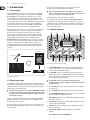
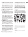
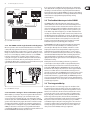
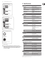
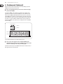
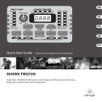
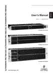
User Manual
SHARK FBQ100
Automatic Feedback Destroyer with Integrated Microphone Preamp,
Delay Line, Noise Gate and Compressor
2
SHARK FBQ100 User Manual
Table of Contents
Thank you........................................................................ 2
Important Safety Instructions....................................... 3
Legal Disclaimer.............................................................. 3
Limited warranty............................................................. 3
1. Introduction................................................................ 4
1.1 The concept........................................................................... 4
1.2 Before you begin................................................................. 4
1.3 Control elements................................................................. 4
2. Applications................................................................ 6
2.1 Wiring the FBQ100: general remarks............................ 6
2.1.1 Connection between microphone
and mixing console.................................................................. 6
2.1.2 Connection between line-level source
and mixing console.................................................................. 6
2.1.3 Connection between mixing console
and power amplifier................................................................ 6
2.1.4 The SHARK used in the monitor path..................... 6
2.1.5 The SHARK used in single channels
and subgroups........................................................................... 7
2.1.6 Automatic “tuning in” of P.A. and
monitor systems........................................................................ 7
2.2 The feedback destroyer in the SHARK......................... 7
2.3 The integrated delay.......................................................... 7
2.4 The noise gate function.................................................... 8
2.5 The low cut filter in the SHARK....................................... 8
2.6 The compressor function................................................. 8
3. Installation.................................................................. 8
3.1 Audio connections.............................................................. 8
4. Specifications.............................................................. 9
5. Rackmount (Optional).............................................. 10
Thank you
Thank you very much for expressing your confidence in BEHRINGER products by
purchasing the SHARK FBQ100.
3
SHARK FBQ100 User Manual
Important Safety
Instructions
Terminals marked with this symbol carry
electrical current of sufficient magnitude
to constitute risk of electric shock.
Use only high-quality professional speaker cables with
¼" TS or twist-locking plugs pre-installed. All other
installation or modification should be performed only
by qualified personnel.
This symbol, wherever it appears,
alerts you to the presence of uninsulated
dangerous voltage inside the
enclosure - voltage that may be sufficient to constitute a
risk of shock.
This symbol, wherever it appears,
alerts you to important operating and
maintenance instructions in the
accompanying literature. Please read the manual.
Caution
To reduce the risk of electric shock, do not
remove the top cover (or the rear section).
No user serviceable parts inside. Refer servicing to
qualified personnel.
Caution
To reduce the risk of fire or electric shock,
do not expose this appliance to rain and
moisture. The apparatus shall not be exposed to dripping
or splashing liquids and no objects filled with liquids,
such as vases, shall be placed on the apparatus.
9. Do not defeat the safety purpose of the polarized
or grounding-type plug. A polarized plug has two blades
with one wider than the other. A grounding-type plug
has two blades and a third grounding prong. The wide
blade or the third prong are provided for your safety. If the
provided plug does not fit into your outlet, consult an
electrician for replacement of the obsolete outlet.
10. Protect the power cord from being walked on or
pinched particularly at plugs, convenience receptacles,
and the point where they exit from the apparatus.
11. Use only attachments/accessories specified by
the manufacturer.
12. Use only with the
cart, stand, tripod, bracket,
or table specified by the
manufacturer, or sold with
the apparatus. When a cart
is used, use caution when
moving the cart/apparatus
combination to avoid
injury from tip-over.
13. Unplug this apparatus during lightning storms or
when unused for long periods of time.
14. Refer all servicing to qualified service personnel.
Servicing is required when the apparatus has been
damaged in any way, such as power supply cord or plug
is damaged, liquid has been spilled or objects have fallen
into the apparatus, the apparatus has been exposed
to rain or moisture, does not operate normally, or has
been dropped.
15. The apparatus shall be connected to a MAINS socket
outlet with a protective earthing connection.
16. Where the MAINS plug or an appliance coupler is
used as the disconnect device, the disconnect device shall
remain readily operable.
Caution
These service instructions are for use
by qualified service personnel only.
To reduce the risk of electric shock do not perform any
servicing other than that contained in the operation
instructions. Repairs have to be performed by qualified
service personnel.
1. Read these instructions.
2. Keep these instructions.
3. Heed all warnings.
4. Follow all instructions.
5. Do not use this apparatus near water.
6. Clean only with dry cloth.
7. Do not block any ventilation openings. Install in
accordance with the manufacturer’s instructions.
8. Do not install near any heat sources such as
radiators, heat registers, stoves, or other apparatus
(including amplifiers) that produce heat.
LEGAL DISCLAIMER
TECHNICAL SPECIFICATIONS AND APPEARANCES
ARE SUBJECT TO CHANGE WITHOUT NOTICE AND
ACCURACY IS NOT GUARANTEED. BEHRINGER,
KLARK TEKNIK, MIDAS, BUGERA, AND TURBOSOUND
ARE PART OF THE MUSIC GROUP (MUSIC-GROUP.COM).
ALL TRADEMARKS ARE THE PROPERTY OF THEIR
RESPECTIVE OWNERS. MUSIC GROUP ACCEPTS NO
LIABILITY FOR ANY LOSS WHICH MAY BE SUFFERED
BY ANY PERSON WHO RELIES EITHER WHOLLY OR
IN PART UPON ANY DESCRIPTION, PHOTOGRAPH
OR STATEMENT CONTAINED HEREIN. COLORS AND
SPECIFICATIONS MAY VARY FROM ACTUAL PRODUCT.
MUSIC GROUP PRODUCTS ARE SOLD THROUGH
AUTHORIZED FULLFILLERS AND RESELLERS ONLY.
FULLFILLERS AND RESELLERS ARE NOT AGENTS OF
MUSIC GROUP AND HAVE ABSOLUTELY NO AUTHORITY
TO BIND MUSIC GROUP BY ANY EXPRESS OR IMPLIED
UNDERTAKING OR REPRESENTATION. THIS MANUAL
IS COPYRIGHTED. NO PART OF THIS MANUAL MAY
BE REPRODUCED OR TRANSMITTED IN ANY FORM
OR BY ANY MEANS, ELECTRONIC OR MECHANICAL,
INCLUDING PHOTOCOPYING AND RECORDING OF ANY
KIND, FOR ANY PURPOSE, WITHOUT THE EXPRESS
WRITTEN PERMISSION OF MUSIC GROUP IP LTD.
ALL RIGHTS RESERVED.
© 2013 MUSIC Group IP Ltd.
Trident Chambers, Wickhams Cay, P.O. Box 146,
Road Town, Tortola, British Virgin Islands
LIMITED WARRANTY
For the applicable warranty terms and conditions
and additional information regarding MUSIC Group’s
Limited Warranty, please see complete details online at
www.music-group.com/warranty.
4
SHARK FBQ100 User Manual
1. Introduction
Please use the enclosed power supply to connect the unit to the mains.
The supply complies with all applicable safety standards.
1.1 The concept
With the SHARK FBQ100 you purchased a device that combines an automatic
Feedback Destroyer using the ingenious search algorithms of our FEEDBACK
DESTROYER FBQ1000, a variable Delay Line (adjustable in msec, feet and
meter), a ULN (Ultra-Low Noise) microphone pre-amp with Phantom Power,
an automatic Noise Gate, a variable Low Cut filter and a Compressor—all in
one ultra-rugged and compact case. Still, the SHARK can be operated intuitively
and expanded to a multi-channel system using another four SHARKs and
an optionally available 19" rack mount kit. The SHARK’s 24-bit A/D and D/A
converters guarantee a precise reproduction of your program material.
High volume levels and the use of ever more sophisticated monitoring systems
with a multitude of speaker cabinets have led to a greater potential risk of
feedback loops in sound reinforcement systems. So far, audio engineers
have been using conventional 1/3-octave equalizers to suppress unwanted
feedback. However, the individual filters of such an EQ, with their relatively
wide bandwidth, have quite an impact on the sound image. With the
BEHRINGER SHARK (minimum bandwidth: 1/60 of an octave) you are now free
to either choose the trial and error method to suppress feedback with graphic
equalizers, or to assign this task to the FBQ100, so that you can give your
music your undivided attention. Using extremely narrow-bandwidth filters,
the SHARK FBQ100 eliminates only unwanted feedback, without affecting
your music.
◊ Please note that all units must be grounded properly. For your own
safety, you should never remove any ground connectors from electrical
devices or power cords or render them inoperative.
Further information can be found in chapter 3 “Installation”.
As a standard the audio inputs and outputs of the BEHRINGER SHARK FBQ100
are fully balanced. If possible, connect the unit to other devices in a balanced
configuration to allow for maximum interference immunity. The automatic servo
function detects unbalanced connections and compensates the level difference
automatically (6 dB correction).
1.3 Control elements
(1)
(2)
(3)
(4)
(5)
Speaker Box
Microphone
(9) (6) (10) (7) (11) (8) (12)
(13)
Fig. 1.2: Front panel control elements of the FBQ100
(1) The CLIP LEVEL METER shows you whether or not the digital circuitry is
driven correctly. Any corrections can be made with the CLIP LEVEL control
(2). Be sure that the CLIP LED won’t light up.
Mixing Console
Power Amp
Fig. 1.1: Typical feedback loop
(2) The CLIP LEVEL control lets you adapt the internal gain optimally to the
digital circuitry. If gain is too high (CLIP LED lights up), raise the CLIP LEVEL
value by turning the control to the right (and vice versa). Thus, you can shift
the operating level upwards/downwards.
1.2 Before you begin
◊ The CLIP LEVEL control does not affect the input/output levels,
Your SHARK was carefully packed in the factory and the packaging is designed
to protect the unit from rough handling. Nevertheless, we recommend that you
carefully examine the carton and its contents for any signs of physical damage,
which may have occurred during transit.
(3) These five LEDs symbolize the units of the parameters that can be adjusted
on the display (4).
◊ If the unit is damaged, please do not return it to BEHRINGER, but notify
(4) The 4-digit DISPLAY reads the absolute values of the adjusted parameters.
your dealer and the shipping company immediately, otherwise claims
for damage or replacement may not be granted. Shipping claims must
be made by the consignee.
The optionally available rack mount kit allows you to mount your BEHRINGER
SHARK in a standard 19" rack, together with another four SHARKs. The rack
mount kit requires 2U of rack space.
Be sure that there is enough air space around the unit for cooling and please do
not place the SHARK on high-temperature devices such as power amps, etc. to
avoid overheating.
but adapts the audio signal as optimally as possible to the threshold of
the digital circuitry.
(5) The FB-D FILTER STATUS LEDs display the status of each of the 12 individual
filters. The SHARK uses four different filter modes:
• Disabled filters (which can be re-enabled with the ACTIVE button). When a
filter is off, its LED is not lit.
• Free filters which automatically search for feedback frequencies and whose
activity is shown by a flashing LED.
• Set filters which can be reconfigured as free (searching) filters, when all
filters are currently in use.
• Permanently set filters which must be RESET to be reconfigured as
free filters.
Once a filter has been set, its LED lights up.
5
SHARK FBQ100 User Manual
(6) The DELAY button allows you to adjust the Delay Line time. Press the button
several times to either choose msec, feet or meter. The last unit selected will
be stored and recalled next time you use the DELAY function. The control LED
lights up while you are making your entries. The setting range is from 0 to
2,500.0 msec, 0 to 2,818.2 feet, and 0 to 859.00 meters. When you are using
high values, the 4-digit display reads the last figure only when you start
editing with the UP/DOWN buttons. Example: for a value of 1,500.0 msec,
the display reads “1500” when you press the DELAY button, and “500.0”
when you start editing. In this way, you can use extremely small steps when
editing parameters.
◊ To speed up the selection, briefly press the key located next to the
UP or DOWN key. The selection speed will be increased with each
additional key press. This function can be used for all parameter edits.
(7) The DOWN button lowers the parameter values shown in the display (4).
(8) The UP button raises these parameter values.
(9) The LOW CUT button lets you enter the high pass filter’s cut-off frequency
(20 to 150 Hz). When set to OFF the filter is inoperative. The control and “Hz”
LEDs light up while you are entering a value. Use the UP/DOWN buttons to
edit. Pressing the LOW CUT button for a longer time (please wait, until all
five parameter LEDs light up) enables the keypad lock feature which prevents
inadvertent editing of parameters and settings. When the keypad lock is
enabled, the LOW CUT key’s control LED starts flashing.
The FILTER LEARN function generates short feedback-causing signals that
are sent back to the FBQ100’s input, where feedbacks are detected and
suppressed. The FILTER LEARN function is an useful tool for live concerts that
prevents filters from being released prematurely. Fixed filters can only be
reconfigured as free, searching filters by means of a RESET. In normal mode,
which is activated after power-up, set filters are automatically released
one after the other, when free filters are needed to search and destroy
feedback frequencies.
◊ To ensure that the FILTER LEARN function works properly, the short
feedback-causing signals are output with a level of -18 dB below digital
maximum. However, the feedback caused during the FILTER LEARN
procedure will be limited by the compressor to -30 dB below digital
maximum. Please note that considerable volume levels can still occur,
which is why you should use the FILTER LEARN function only before the
concert/event begins.
(13) Enable the ACTIVE button to set inoperative filters to automatic search
mode. When this button is up (control LED is off), those filters are inoperative
which have not yet found a feedback frequency. Pressing the ACTIVE button
for a longer time (please wait, until all five parameter LEDs light up) enables
the RESET function. All filters will be reset, i.e. set to automatic search mode.
(14)
(15)
(23) (16)
(10) Use the GATE button to adjust the threshold of the internal Noise Gate
(-96 dB through -44 dB). When set to OFF, the Noise Gate is inoperative.
The control LED of the GATE button lights up while you are entering
a value. Pressing the GATE button for a longer time (please wait,
until all five parameter LEDs light up) enables the GATE LEARN function,
which automatically sets the Noise Gate threshold by analyzing the program
material and adjusting the value accordingly (value detected plus 2 dB).
In GATE LEARN mode, the GATE key’s control LED starts flashing. As long as
the LED flashes, the detected value is read on the display, when the LED stops
flashing, the value is raised by +2 dB.
(11) The COMPRESSOR button gives you access to two parameters that let
you adapt the FBQ100’s Compressor function to the program material.
Press the button once to adjust the DENSITY parameter, which controls the
compression density from 0 (no processing) to 100 (maximum compression).
Press the COMPRESSOR button a second time to adjust the SPEED
parameter which controls the Compressor’s attack and release times
from 10 to 1000 msec. The “msec” LED lights up as soon as you select the
SPEED parameter.
(12) The FILTER key allows you to set the feedback detection sensitivity within a
range from 1 (no sensitivity) through 100 (full sensitivity). The default value
is 50. The control LED lights up during data entry. Briefly press the FILTER key
a second time to edit the maximum attenuation of the FB-D filter (from -3 dB
through -48 dB in steps of 3). Pressing the FILTER key longer (please wait,
until all five parameter LEDs light up) activates the FILTER LEARN function,
which automatically searches for feedback frequencies and assigns free
filters to the frequencies found. Now you can enter the number of filters
(standard: 9) to be used for permanent feedback suppression. Although the
remaining filters are also used to eliminate feedback frequencies, they are
released once new feedback occurs. Pressing the FILTER key once again
activates the FILTER LEARN function.
◊ When both FILTER LED and display stop flashing, the FILTER LEARN
function has been completed. Press the FILTER key to cancel the
function. After a short delay, the unit returns to the FILTER menu.
(17)
(18)
(19)
(20)
(21)
(22)
Fig 1.3: Rear panel control elements and connectors of the FBQ100
(14) This is the SHARK’s balanced XLR OUTPUT.
(15) This is the SHARK’s balanced XLR INPUT.
(16) The MIC GAIN control adjust the input signal gain, when the INPUT LEVEL
switch (21) has been pressed (position: MIC). To adjust microphone levels
you can use the CLIP LEVEL indicator, by setting the CLIP LEVEL control to
mid-travel position. Please make sure that the CLIP LED will not light up.
(17) Use the POWER SUPPLY CONNECTOR to hook up the SHARK’s external
power supply.
(18) This is the SHARK’s balanced JACK OUTPUT, which carries the same signal as
the XLR output.
(19) The OUTPUT LEVEL switch controls the reference level provided by the
outputs of the FBQ100. Possible values are: +4 dBu or microphone level.
(20) This is the SHARK’s balanced JACK INPUT, which is wired in parallel to the
XLR input.
6
SHARK FBQ100 User Manual
(21) Use the INPUT LEVEL switch to select the input sensitivity (microphone or
line levels). In LINE mode, you can use the CLIP LEVEL control to adapt the
internal level settings to the digital circuitry. Please make sure that the
CLIP-LED will not light up.
(22) The PHANTOM switch enables the Phantom Power supply required for
condenser microphones.
(23) The PHANTOM CONTROL LED lights up when Phantom Power is on.
2.1.3 Connection between mixing console and
power amplifier
When you use the SHARK as a Delay Line unit for speaker systems placed at
various positions (see chapter 2.3), you should connect the SHARK between the
console’s output and the input of the power amp driving the “delayed” speakers.
Delayed Speakers
Speakers on Stage
2. Applications
2.1 Wiring the FBQ100: general remarks
With its great versatility the SHARK can be used for a variety of applications.
This chapter describes connection and configuration examples of the most
common applications.
2.1.1 Connection between microphone and
mixing console
In live applications it is often useful to protect specific single microphones against
feedback. We therefore recommend that you connect the SHARK between your
microphone and a microphone input on your mixing console (OUTPUT LEVEL
switch set to MIC). If all mic inputs are in use, you can set the SHARK’s OUTPUT
switch to +4 dBu (switch pressed) and adapt the output signal of your SHARK to
a line input on your console using the MIC GAIN control. To prevent the occurrence
of subsonics you can activate the SHARK’s Low Cut filter. Switch on Phantom
Power when you are using condenser microphones.
Master Out
+4 dBu
Line
Fig. 2.3: The SHARK connected between console and power amp
2.1.4 The SHARK used in the monitor path
Mic In / Line In
Mic / +4 dBu Mic
Fig. 2.1: The SHARK connected between microphone and microphone input on console
2.1.2 Connection between line-level source and
mixing console
At first sight, this configuration may seem to make no sense, because line-level
sources usually have no problems with feedback frequencies. However, acoustic
instruments are often equipped with so-called piezo pickups which are
susceptible to feedback. In such a case, we recommend that you route the audio
signal through the SHARK before feeding it into the console.
Line In
+4 dBu
Line
Fig. 2.2: The SHARK connected between acoustic guitar and line input on console
Inserting the FBQ100 in the monitor path of your mixing console gives you
utmost protection against unwanted feedback. Monitor paths are particularly
susceptible to feedback, because on stage there are usually several microphones
and speakers placed close to each other. Especially vocal microphones pose
some problems, because their volume levels must be fairly high to be able to
“compete” with other instruments, and often these microphones are hand-held
and hence carried around on stage. It is therefore useful to protect the monitor
path against feedback. In particular, when used in the monitor path, the SHARK
produces a positive side effect in that it improves both sound and volume of the
monitors. By filtering interference it makes the sound more transparent and by
eliminating unwanted feedback it allows for raising the volume of the monitors,
an effect that is usually welcomed by musicians on stage. Another advantage
when using this configuration: one SHARK can control several microphones. As at
least four monitor paths are used in a typical live application, all you need are
four SHARKs to give you optimum feedback protection.
7
SHARK FBQ100 User Manual
Monitoring
If you are using not just one FBQ100 for the monitor path, you should employ
some additional units to safeguard critical signal paths. Experience has shown
that during a concert the musicians on stage usually want their instruments
made louder in the monitors. With the SHARK you can raise the volume without
running the risk of feedback. When the concert begins the FBQ100 automatically
tracks and removes varying feedback signals produced by “moving”
vocal microphones.
P.A.
2.2 The feedback destroyer in the SHARK
+4 dBu
Monitor
Out
Line
The SHARK identifies feedback by splitting the entire frequency spectrum
(20 Hz to 20 kHz) into sections of 1/60 of an octave and determining the level
of each of these bands. The values calculated are then referenced to the level
of the overall signal. The resulting level difference determines whether or not
a filter is set. The SHARK allows you to adapt these decisive parameter to your
needs: within a range from 1 through 100 you can edit the feedback detection
sensitivity. The standard setting is 50, which ensures the best possible detection
of feedback for the majority of applications. For speech-only applications you can
raise the feedback detection threshold towards 100, which enables the algorithm
to detect and remove feedback even more quickly. Vice versa, lower values
provide for a more stable feedback suppression responding less to wanted
feedback-like signal portions produced by guitars or keyboards.
Master Out
Fig. 2.4: Two SHARKs in the monitor path
2.1.5 The SHARK used in single channels and subgroups
Whenever you want to make sure that wanted feedback such as the feedback
sounds produced by a guitar won’t be removed, you should insert one or several
FBQ100 into “feedback-prone” single channels (e.g. vocals) or subgroups of your
mixing console! Route all channels that are susceptible to feedback (e.g. all vocal
mics) to one or several subgroups, in which you insert one or several SHARKs.
In this way, all channels that are less liable to produce feedback (e.g. those
carrying line-level signals, or instrumental microphones with lower volumes)
can pass the console unaltered, while only critical microphone channels are
controlled by the FBQ100. Thus, you can protect your sound reinforcement system
against feedback and still use wanted feedback sounds.
Send
Return
Out
+4
dBu
Line
In
Return
Mixer
Insert Point
Send
Ground
Ground
Fig. 2.5: The SHARK in the insert path
2.1.6 Automatic “tuning in” of P.A. and monitor systems
With the FBQ100 you can improve the protection against feedback even before
a concert begins, simply by “tuning in” your sound reinforcement system:
once the system has been installed and set up, open all microphone channels
and monitor paths, then enable FILTER LEARN mode on your FBQ100. The SHARK
generates short feedback-causing signals, which are then sent back to its input
and suppressed by the filters. These filters are permanently assigned and can
be reconfigured as free searching filters only by means of a RESET. Without the
SHARK you could raise the overall volume level only until the first feedback
occurs. But with the FBQ100 you’ve got considerably more headroom! Please note
that the FILTER LEARN mode is limited to about 15 seconds.
In FILTER LEARN mode, feedback is generated and suppressed automatically.
Whenever it detects feedback, the FBQ100 selects the filter parameters
automatically to efficiently remove the feedback. As the filter is set to the
frequency detected, this mode is ideally suitable for suppressing constant
feedback frequencies produced by “fixed” microphones, e.g. those used on
drums. Once set, the filters automatically enters lock mode, i.e. the frequency
remains fixed but width and depth of the filter are still being adapted to the
signal. The filter width is enlarged whenever the feedback frequency shifts
slightly. If feedback persists, gain is reduced even more and kept low to prevent
feedback from recurring.
All microphones that are moved during a performance (e.g. hand-held
vocal microphones) are usually susceptible to varying feedback frequencies,
which should be suppressed in automatic search mode (entered when you
power up the SHARK). Much like in FILTER LEARN mode, a filter automatically
determines the ideal settings for all parameters, in order to suppress feedback.
However, once all filters have been set, the filter first activated gets reset to
automatic search mode. Thus, the SHARK makes sure that there is always one free
filter to identify and remove new feedback frequencies. If your music contains
wanted feedback elements (e.g. guitar feedback), the SHARK will suppress these
too, because it is impossible from a physical point of view to distinguish wanted
from unwanted feedback. Section 2.1.6 provides some information on how to get
around this physical problem.
2.3 The integrated delay
In addition to speakers on or near the stage, major-scale installations often
have speaker groups positioned at a distance to the stage or flown above the
audience, in order to provide listeners away from the stage with direct sound.
However, since sound needs some time to travel around (343.6 m/sec at 20°C,
accelerates by 0.6 m/sec per °C), it reaches the audience not simultaneously
but gets delayed by a certain amount. To make up for the different run times
between stage and remote speakers, the latter must be provided with an
electronically delayed signal, which is usually done by means of special-purpose
Delay devices. You won’t need them, however, when you’ve got a SHARK,
as the FBQ100 integrates a Delay Line circuit giving you the same convenience
of operation as dedicated devices. Simply measure the distance between the
various speaker groups and enter this value (in meters or feet). Chapter 2.1.3
shows you how to wire the FBQ100 in this type of application.
8
SHARK FBQ100 User Manual
2.5 The low cut filter in the SHARK
Gallery
Speaker
Stage
Speaker
Gallery
Stage
Fig. 2.6: Sound reinforcement application with different speaker positions
In miking it is quite common to fade out low-frequency signal portions such as
stage rumble, pop sounds or other types of interference. Frequencies of that kind
often have high amplitudes and not only affect the sound image but can also
damage power amps and/or loudspeakers. The SHARK is equipped with a tunable
high pass filter that features a very high slope. Press the LOW CUT button to tune
the cutoff frequency from 20 Hz through 150 Hz with the UP/DOWN buttons,
so that interference noise is faded out as perfectly as possible, while the wanted
signals remains unaffected.
2.6 The compressor function
2.4 The noise gate function
The main task of a Noise Gate is to separate unwanted background noise from
wanted signals and remove noise “inaudibly”. A so-called downward Expander
automatically reduces the overall level of all signals below an adjustable
threshold and thus expands the dynamic range of the program material.
In live or stage applications and multi-microphone systems, in particular, the
SHARK has a variety of possible uses: as a moderately and accurately set Gate it
efficiently suppresses background noise, compressor-induced noise build-up and
crosstalk between microphones, without producing any unpleasant side effects.
A typical Gate application is the processing of vocal tracks. Especially when using
a Compressor, the distance between microphone and singer is critical: as the
distance increases, more and more disturbing background noise is picked up.
Use the Gate function to fade out unwanted interference “inaudibly” during
music pauses. In live applications, e.g. crosstalk of drum and piano tracks can be
suppressed or acoustically “contaminated” recordings can be cleaned.
When a singer sings into a stage microphone, the background noise is masked
and hence not perceived. During music pauses, however, the microphone picks
up the noise produced by the P.A. system and monitor speakers, which can lead
to unpleasant feedback.
When you insert the SHARK in a vocal channel and adjust it so that it mutes the
channel, as long as the microphone is not in use, susceptibility to feedback can
be reduced enormously. Basically, all stage microphones should be treated in
this way.
The GATE LEARN function helps you adjust the Gate threshold. Use this function
before the concert and after the sound check. If the adjusted value yields
unsatisfactory results, the UP/DOWN buttons can be used to fine-tune the Gate,
until it closes only during signal pauses and suppresses interference efficiently.
Output
In broadcast and recording applications, signal levels often exceed the
headroom of signal-processing devices, which means that the dynamic range
must be reduced to avoid distortion. This is usually accomplished by the use of
Compressors or Limiters, which use an automatic gain control circuit to reduce
the signal level during loud passages. In this way, it is possible to compress the
dynamics of a microphone channel from 90 dB to 50 dB or less, which ensures
the troublefree further processing of signals, e.g. in broadcast, stage or
recording applications.
The Compressor monitors the program material using an adjustable threshold
and continuous level control process, i.e. above threshold the signal gain is
reduced, depending on threshold overshoot. Usually, the threshold is set to
somewhere below the operating level to allow for a musical compression of the
upper level range.
The FBQ100 allows you to set two Compressor parameters. The first one, DENSITY,
compresses the program material in a range from 0 (bypass) through 100
(max. compression). The second parameter, SPEED, allows you to adjust the
Compressor function in the time domain. Here, you can set the control speed
of the Compressor from 10 through 1000 msec. Use small values to make the
Compressor respond to smallest level differences, and high values to process
dynamics “inaudibly”.
3. Installation
3.1 Audio connections
As standard, the BEHRINGER FBQ100 is installed with electronically servobalanced inputs and outputs. The new circuit design features automatic hum and
noise reduction for balanced signals and thus allows for trouble-free operation,
even at high operating levels. Externally induced mains hum etc. will be
effectively suppressed.
Cable
Input
Pin 1
Ground
2
1
Pin 3 = (-) Signal
Shield
1
2
(+) Signal + Hum
Pin 2 = (+) Signal
3
(-) Signal + Hum
3
Positive
(+)Hum + Signal
Negative
(-)Hum + Signal
2 x Signal
= Signal + 6 dB
RFI and Hum
Fig. 3.1: Compensation of interference with balanced connections
9
SHARK FBQ100 User Manual
Unbalanced ¼" TS connector
strain relief clamp
sleeve
tip
4. Specifications
Audio Inputs
Connectors
XLR and ¼" TRS jack
Impedance
6 kΩ balanced, 3 kΩ unbalanced
Nominal operating level
Microphone or line level source
(switchable)
Max. input level
+19 dBu at microphone level and
line level
sleeve
(ground/shield)
tip
(signal)
Audio Outputs
Connectors
XLR and ¼" jack
Impedance
60 Ω balanced, 30 Ω unbalanced
strain relief clamp
Nominal operating level
sleeve
ring
tip
Microphone level source or +4 dBu
(switchable)
Max. output level
+20 dBu at +4 dBu nominal level,
-12 dBu at microphone level
Balanced ¼" TRS connector
sleeve
ground/shield
ring
cold (-ve)
tip
hot (+ve)
System Specifications
Frequency response
10 Hz to 21 kHz
Noise
> 92 dB at line level, unweighted,
22 Hz to 22 kHz
> 89 dB at microphone level,
unweighted,
22 Hz to 22 kHz
THD
0.007% typ. @ +4 dBu, 1 kHz, gain 1
For connection of balanced and unbalanced plugs,
ring and sleeve have to be bridged at the stereo plug.
Balanced use with XLR connectors
Digital Processing
2 1
3
Converters
input
1 = ground/shield
2 = hot (+ve)
3 = cold (-ve)
Display
Type
1
24-bit Sigma-Delta,
64/128-times oversampling
4-digit numeric LED display
2
3
output
For unbalanced use, pin 1 and pin 3
have to be bridged
Fig. 3.2: Different plug types
◊ Please ensure that only qualified persons install and operate the
SHARK. During installation and operation the user must have sufficient
electrical contact to earth. Electrostatic charges might affect the
operation of the SHARK!
Power Supply
Mains Voltages/Power Consumption
USA/Canada
120 V~ 60 Hz 19 W
U.K./Australia
240 V~ 50 Hz 20.5 W
Europe
230 V~ 50 Hz 20 W
Korea
220 V~ 50 Hz 20 W
China
220 V~ 50 Hz 20 W
Japan
100 V~ 50/60 Hz 18 W
Physical
Dimensions (H x W x D)
approx. 2.2 x 3.5 x 5.2" / 56 x 88 x 132 mm
Net Weight
approx. 0.84 lbs / 0.38 kg
BEHRINGER is constantly striving to maintain the highest professional standards. As a result of these efforts,
modifications may be made from time to time to existing products without prior notice. Specifications and
appearance may differ from those listed or illustrated.
10
SHARK FBQ100 User Manual
5. Rackmount (Optional)
With the available rackmount (optional) you have the possibility to place five
SHARKs on two units of space in your rack.
◊ Before you begin with the work, please disconnect the Power Supply
Units from the SHARKs!
To mount the SHARKs on the rackmount you should use the supplied screws
(type M3). You need two screws to fix one FBQ100 onto the rackmount. In the
bottom of your SHARK you will find two little threads. You have to position the
single SHARKs on the rackmount, so that the threads correspond to the cutouts
of the rackmount (see fig. 5.1). Now you can fix the FBQ100 onto the rackmount.
Just take a cross-point screwdriver and tighten both screws loosely. After you
have fixed all SHARKs on the rackmount, you can adjust the devices and tighten
all screws solidly.
Bottom FBQ100
Thread 1
Thread 2
Cutout 1
Cutout 2
Front Rackmount (Bottom View)
Fig. 5.1: Installation of the FBQ100 on the available rackmount (optional)
◊ Please, only use the supplied screws to install the SHARKs on the
rackmount. Longer or thicker screws can damage the electronics inside
of the device and doing so will void your warranty rights.
You will need 2 units of space for the FBQ100 rackmount. For technical reasons a
little gap remains above the rackmount.
11
SHARK FBQ100 User Manual
FEDERAL COMMUNICATIONS
COMMISSION COMPLIANCE
INFORMATION
SHARK FBQ100
Responsible Party Name:
MUSIC Group Services US Inc.
Address:
18912 North Creek Parkway,
Suite 200 Bothell, WA 98011,
USA
Phone/Fax No.:
Phone: +1 425 672 0816
Fax: +1 425 673 7647
SHARK FBQ100
complies with the FCC rules as mentioned in the following paragraph:
This equipment has been tested and found to comply with the limits for a Class B
digital device, pursuant to part 15 of the FCC Rules. These limits are designed
to provide reasonable protection against harmful interference in a residential
installation. This equipment generates, uses and can radiate radio frequency
energy and, if not installed and used in accordance with the instructions, may cause
harmful interference to radio communications. However, there is no guarantee that
interference will not occur in a particular installation. If this equipment does cause
harmful interference to radio or television reception, which can be determined
by turning the equipment off and on, the user is encouraged to try to correct the
interference by one or more of the following measures:
• Reorient or relocate the receiving antenna.
• Increase the separation between the equipment and receiver.
• Connect the equipment into an outlet on a circuit different from that to which the
receiver is connected.
• Consult the dealer or an experienced radio/TV technician for help.
This device complies with Part 15 of the FCC rules. Operation is subject to the
following two conditions:
(1) this device may not cause harmful interference, and
(2) this device must accept any interference received, including interference that may
cause undesired operation.
Important information:
Changes or modifications to the equipment not expressly approved by MUSIC Group
can void the user’s authority to use the equipment.
We Hear You