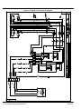
1
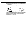
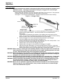
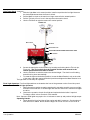
POW’R Lite Kit for
Towable Generators
TS25 through TS80
Installation & Operating Manual
9/09
MN2421
Any trademarks used in this manual are the property of their respective owners.
WARNING:
CALIFORNIA PROPOSITION 65 WARNING:
Engine exhaust from this product contains chemicals known
to the state of California to cause cancer, birth defects and
other reproductive harm.
WARNING:
CALIFORNIA PROPOSITION 65 WARNING:
Battery posts, terminals and related accessories are known to
the state of California to cause cancer, birth defects and other
reproductive harm.
Table of Contents
Section 1
Product Safety Information . . . . . . . . . . . . . . . . . . . . . . . . . . . . . . . . . . . . . . . . . . . . . . . . . . . . . . . . . . . . . . . . . . . . . . .
Section 2
General Information . . . . . . . . . . . . . . . . . . . . . . . . . . . . . . . . . . . . . . . . . . . . . . . . . . . . . . . . . . . . . . . . . . . . . . . . . . . . . .
Limited Warranty . . . . . . . . . . . . . . . . . . . . . . . . . . . . . . . . . . . . . . . . . . . . . . . . . . . . . . . . . . . . . . . . . . . . . . . . . . . . . .
Section 3
Receiving & Installation . . . . . . . . . . . . . . . . . . . . . . . . . . . . . . . . . . . . . . . . . . . . . . . . . . . . . . . . . . . . . . . . . . . . . . . . . . .
Receiving & Inspection . . . . . . . . . . . . . . . . . . . . . . . . . . . . . . . . . . . . . . . . . . . . . . . . . . . . . . . . . . . . . . . . . . . . . . . .
Installation of Optional POW’R LITE Kit . . . . . . . . . . . . . . . . . . . . . . . . . . . . . . . . . . . . . . . . . . . . . . . . . . . . . . . . . .
Installation of TS80 Electric Winch . . . . . . . . . . . . . . . . . . . . . . . . . . . . . . . . . . . . . . . . . . . . . . . . . . . . . . . . . . . . . . .
Section 4
Operation . . . . . . . . . . . . . . . . . . . . . . . . . . . . . . . . . . . . . . . . . . . . . . . . . . . . . . . . . . . . . . . . . . . . . . . . . . . . . . . . . . . . . . . .
Light Tower Setup . . . . . . . . . . . . . . . . . . . . . . . . . . . . . . . . . . . . . . . . . . . . . . . . . . . . . . . . . . . . . . . . . . . . . . . . . . . . .
Flood Light Operation . . . . . . . . . . . . . . . . . . . . . . . . . . . . . . . . . . . . . . . . . . . . . . . . . . . . . . . . . . . . . . . . . . . . . . . . . .
Section 5
Troubleshooting and Maintenance . . . . . . . . . . . . . . . . . . . . . . . . . . . . . . . . . . . . . . . . . . . . . . . . . . . . . . . . . . . . . . . . .
Flood Light Bulb Replacement . . . . . . . . . . . . . . . . . . . . . . . . . . . . . . . . . . . . . . . . . . . . . . . . . . . . . . . . . . . . . . . . . .
Periodic Inspections . . . . . . . . . . . . . . . . . . . . . . . . . . . . . . . . . . . . . . . . . . . . . . . . . . . . . . . . . . . . . . . . . . . . . . . . . . .
Connection Diagram . . . . . . . . . . . . . . . . . . . . . . . . . . . . . . . . . . . . . . . . . . . . . . . . . . . . . . . . . . . . . . . . . . . . . . . . . . .
MN2421
1−1
2−1
2−1
3−1
3−1
3−1
3−6
4−1
4−1
4−2
5−1
5−1
5−1
5−2
Table of Contents i
ii Table of Contents
MN2421
Section 1
Product Safety Information
This kit can be installed on several models of the Baldor Towable Generators. This manual
contains Installation and Operation instructions for the POW’R LITE Kit and components only.
Please refer to the manual for the generator for operation and maintenance instructions for the
generator portion of the product.
Responsibility
When your generator is delivered, it becomes the responsibility of the owner/operator of the
generator set to prevent unsafe conditions and operation of the equipment. Some
responsibilities include (but are not limited to) the following:
1. It is the responsibility of the owner/operator of this generator to ensure that this
equipment is correctly and safely installed.
2. It is the responsibility of the owner/operator of this generator to ensure that this
equipment, when installed fully complies with all federal, state and local codes.
3. It is the responsibility of the owner/operator of this generator to ensure that any person
operating this equipment has been properly trained.
4. It is the responsibility of the owner/operator of this generator to ensure that any person
operating this equipment has access to all manuals and information required for the
safe use and operation of this equipment.
5. It is the responsibility of the owner/operator of this generator to ensure that it is properly
maintained and safety inspected at regular scheduled intervals.
6. It is the responsibility of the owner/operator of this generator to ensure that any person
who has not been trained on the safe use of this equipment does not have access to
this equipment.
Read This Manual Thoroughly
If you do not understand any concept, any procedure, any safety warning statement, any safety
caution statement or any portion of this manual, seek expert advise. Make sure you understand
the information in this manual so that you can safely enjoy the full use of this generator.
Symbols
This symbol is shown throughout the manual to indicate a connection to ground reference point.
Indicates a potentially hazardous situation which, if not avoided, could result in injury or death.
Indicates a potentially hazardous situation which, if not avoided, could result in injury or death.
WARNING: When erecting or stowing the mast assembly, be aware of the pinch points such as where the
tower structures join or where the cable and winch are located. Careless operation can result
in injury. Keep extremities away from moving parts to avoid injury.
WARNING: Before erecting the mast assembly, be certain that the outriggers are properly set to stabilize
the light tower and that they are secure and are not damaged. Erecting the mast without
setting the outriggers can cause the light tower to tip over when raising the mast.
WARNING: Before erecting the mast assembly, be certain that there are no overhead wires. Contact with
overhead wiring presents an electrical shock hazard that may cause severe injury or death.
WARNING: Before erecting the mast assembly, be certain that there are no overhead obstructions that
the mast will hit when raising it. Hitting an object (tree limb etc.) may damage the mast or
cause the light tower to tip over and may result in injury or property damage.
WARNING: The mast assembly must remain in the stowed position until the outriggers are properly set to
stabilize the trailer . Erecting the mast without setting the outriggers can cause the light
tower set to tip over when raising the mast.
MN2421
Product Safety Information 1-1
WARNING: Never attempt to move the POW’R LITE when the mast is in the vertical position. All
Outrigger and trailer jacks must remain in position and the trailer level until the mast is in its’
stowed position. Failure to follow this warning may result in severe injury and property
damage if the trailer tips over.
WARNING: Never move or reposition a light tower when the mast is extended or in the vertical position.
Unless the mast is in its stowed position, it may contact overhead wires or cause the light
tower to be unbalanced or tip over.
WARNING: Always wear safety glasses with side shields and hearing protection when working near the
light tower.
WARNING: Some parts of this light tower rotate during operation. Rotating parts can present extreme
danger if clothing or body extremities are caught by the rotating part and can cause serious
or fatal injury. Never touch a part of the light tower until the engine has been stopped and all
rotating parts are completely stopped. Also, disconnect the battery terminals to prevent
accidental engine rotation during servicing.
WARNING: Be sure that you understand how to stop the engine quickly in case of an emergency situation.
Become familiar with the controls and safety systems provided with this light tower.
WARNING: Never allow children or pets to be in the area where the light tower is running. The light tower
and the equipment being powered by the light tower may cause injury or death.
WARNING: Never operate the light tower indoors or in a poorly ventilated area such as a tunnel or cave.
Exhaust fumes are extremely dangerous to all personnel that are in or in contact with that
area.
WARNING: When operating this light tower remain alert at all times. Never operate machinery when
physically or mentally fatigued, or while under the influence of alcohol, drugs or medication.
WARNING: Operate the light tower only on a level surface. If the light tower is tilted during operation, fuel
spillage may result. Gasoline and diesel fuel are flammable and can cause fire, explosions,
injury or death.
WARNING: Keep light tower at least three feet away from buildings and other structures.
WARNING: Keep light tower away from flammable or hazardous materials (trash, rags, lubricants,
explosives, paints etc.) and grass or leaf build up.
WARNING: Keep a fire extinguisher near the light tower during use. An extinguisher rated “ABC” by the
National Fire Protection Association is appropriate.
Burn Statements
WARNING: Light fixtures become extremely hot during use. To prevent severe burns, do not touch light
fixtures, bulbs or other components until they have cooled and no longer present a burn hazard.
Wear protective clothing when placing the tower in the stowed position after use and do not allow
any person to touch the light fixtures.
WARNING: Parts of this light tower are extremely hot during and after operation. To prevent severe
burns, do not touch any part until you have first determined if the part is hot. Wear protective
clothing and after use allow sufficient time for parts to cool before touching.
WARNING: Disconnect all electrical wires and load devices from light tower power outlets before
servicing the light tower. Electrical shock can cause serious or fatal injury. Always treat
electrical circuits as if they are energized.
Caution Statements
Caution: Never start the engine with any of the lights on, or with any electrical load connected, as
damage to the light tower may result.
Caution: Never stop the engine with any of the lights on, or with any electrical load connected, as
damage to the light tower may result.
Caution: Careless handling or storage of the light fixtures can damage the fixtures, lenses, and/or bulbs.
Caution: Before towing, be sure that the jack and outriggers are properly and securely stowed for
travel to prevent trailer damage.
1-2 Product Safety Information
MN2421
Section 2
General Information
Thank you for purchasing your POW’R LITE Kit. This manual contains information you need to safely and efficiently
install and operate your POW’R LITE Kit option. During the preparation of this manual every effort was made to ensure
the accuracy of its contents. A separate owner’s manual for the generator is supplied with the generator for your use.
Please refer to that manual for information relative to engine operation, maintenance, recommendations and additional
safety warnings.
Copyright Baldor E 2009. All rights reserved.
This manual is copyrighted and all rights are reserved. This document may not, in whole or in part, be copied or
reproduced in any form without the prior written consent of Baldor Electric Company, Inc.
Baldor Generators have earned the reputation of being high quality and dependable. We take pride in this fact and
continue to keep our quality standards high on our list of priorities. We are also constantly researching new technological
ideas to determine if they could be used to make our generator sets even better.
Baldor makes no representations or warranties with respect to the contents hereof and specifically disclaims any implied
warranties of fitness for any particular purpose. The information in this document is subject to change without notice.
Baldor assumes no responsibility for any errors that may appear in this document.
Limited Warranty
Baldor will replace or repair free of charge any part or parts of the generator of their manufacture that are defective in
workmanship and materials for a period of time as set forth in the Warranty Period chart below. All Baldor products
requiring warranty service shall be transported or shipped freight pre−paid to a Baldor Generator repair facility.
Notification of the defect or problem, a description of the manner in which the Baldor generator is used, and the name,
address and telephone number of the customer requiring warranty service must be included. Baldor is not responsible for
removal and shipment of the Baldor product to the service center or for the reinstallation of the Baldor product upon its
return to the customer, or any incidental or consequential damages resulting from the defect, removal, reinstallation,
shipment or otherwise. Problems with Baldor products can be due to improper maintenance, faulty installation,
non−Baldor additions or modifications, or other problems not due to defects in Baldor workmanship or materials. If a
Baldor Generator repair facility determines that the problem with a Baldor product is not due to defects in Baldor
workmanship or materials, then the customer will be responsible for the cost of any necessary repairs. Genset engines
are covered under the engine manufacturers warranty. Proper engine maintenance is required. Any request for engine
warranty or repair should be made directly with the engine manufacturers warranty center. See engine manufacturers
data for applicable engine warranty periods and location of repair centers. This Limited Warranty and Service Policy
represents Baldor s sole and exclusive warranty obligation with respect to Baldor products. Baldor’s liability to a
customer or any other person shall not exceed Baldor’s sales price of the applicable Baldor product. BALDOR
DISCLAIMS ALL OTHER EXPRESSED AND IMPLIED WARRANTIES INCLUDING THE IMPLIED WARRANTIES OF
FITNESS FOR A PARTICULAR PURPOSE AND MERCHANTABILITY.
Warranty Period
Generator Series
Portable Products (Premier, Powerchief,
DG Series)
Towable Products (TS)
POW’R LITE Light Towers
Labor*
Parts
1 Year
3 Years
1 Year or 3,000 Hours
1 Year or 3,000 Hours
3 Years or 3,000 Hours
3 Years or 3,000 Hours
Light Fixture, Lamps and Ballasts are excluded from
any warranty coverage
3 Years or 1,000 Hours
3600 RPM Standby Systems
1 Year or 1,000 Hours
(Some AE Models)
1800 RPM Standby Systems
1 Year or 3,000 Hours
3 Years or 3,000 Hours
(Some AE Models, DLC, GLC)
Industrial Standby Systems
1 Year or 1,000 Hours
2 Years or 1,000 Hours
Industrial Prime Power Systems
1 Year or 1,000 Hours
1 Year or 1,000 Hours
International
1 Year or 1,000 Hours
1 Year or 1,000 Hours
* For products covered under labor coverage, travel expenses will be allowed up to 7 hours straight labor or 300 miles,
whichever occurs first, and only applies to permanently wired and mounted products (AE, DLC, GLC, IDLC). You must
save the purchase receipt. Proof of purchase, date, serial number and model number will be required for all portable and
Towable products to qualify for any warranty consideration. A start−up inspection form/warranty registration must be
completed in its entirety and submitted to Baldor Generators within 30 days of start−up to qualify for any warranty
consideration, excluding: Portables, Towables and Light Towers.
MN2421
General Information 2-1
2-2 General Information
MN2421
Section 3
Receiving & Installation
Receiving & Inspection When you receive your generator, there are several things you should do immediately.
1.
Observe the condition of the shipping container and report any damage immediately to
the commercial carrier that delivered your system.
2. Verify that the part number of the system you received is the same as the part number
listed on your purchase order.
3. If the system is to be stored for several weeks before use, be sure that it is stored in a
location that conforms to published storage temperature and humidity specifications.
WARNING: Never stand under or close to an object that is being hoisted or lift into position. Accidents
happen and if the object falls or tips over you or someone else could be crushed by the
weight of the object causing severe injury or death to to yourself or others. Always remain a
safe distance from the object and always wear protective head gear (hard hat).
Figure 3-1 and Table 3-1 show the overall dimensions of the POW’R LITE kit.
Refer to the towable generator manual for the dimensions of the towable generator, MN2417.
Figure 3-1 Overall Dimensions
Light Mast Kits:
14.00001
TS25/35
14.00001-G2 TS45/60/80
TSLM35T - fits TS25/35 Towable Generators
TSLM80T - fits TS45/60/80 Towable Generators
Maximum
Extension
with Lights
TS25/35 Both Tilt and Lift Winches are mechanical
TS45/60/80 Tilt is Mechanical, Lift Winch is electric
Note: Optional Electric Winch kits may be ordered for
either or both winches in all models.
A
C
Lift Winch
Minimum
Extension
with Lights
Tilt Winch
A2
A1
B
MN2421
Receiving & Installation 3-1
Table 3-1 POW’R LITE Option Dimensions
A (max)
33’ 8”
33’ 8”
35’ 3−3/4”
35’ 3−3/4”
35’ 3−3/4”
Generator
TS25
TS35
TS45
TS60
TS80
A1 (min)
11’ 5−1/2”
11’ 5−1/2”
16’ 9−3/8”
16’ 9−3/8”
16’ 9−3/8”
A2 (max)
92.20
92.20
112.25
112.25
112.25
B
159.04
159.04
162.25
162.25
162.25
C
134.13
134.13
135.89
135.89
135.89
Installation of Optional POW’R LITE Kit
Before completion of the Generator installation and start−up, the POW’R LITE feature should be
installed while the battery is disconnected (as received from the factory). Be sure to have a lift
available to raise heavy components into position and hold them while they are fastened securely
in place. A fork lift or other lift device is recommended.
First, several brackets need to be installed, refer to Figure 3-2. The hitch and other items are not
shown to enhance viewing of items being installed.
1. Remove the five (5) screws and associated hardware shown in Figure 3-2.
The captive nuts must be pushed out to allow clearance for new bolts to be installed.
2. Locate the Mast Support bracket and associated hardware shown in Figure 3-2.
3. Install Mast Support bracket where the five (5) screws were removed in step 1,
securely tighten all hardware.
4. Locate the Yoke bracket and associated hardware shown in Figure 3-2.
5. Install Yoke bracket at the lift ring as shown, securely tighten all hardware.
6. Locate Outrigger Support assembly, three Hold Down Plates and associated hardware
shown in Figure 3-2.
7. Raise the Outrigger Support assembly close to the “Front Frame Member” so that the
three tabs rest on the forward surface of the frame member.
8. Hold in position and place the Hold Down Plate on top of the Outrigger Support
assembly so it is in good contact with the frame member and secure using associated
hardware, see Figure 3-2. Repeat for all 3 Hold Down Plates.
9. Securely tighten all hardware.
10. Install the 3 cable clamps on the front panel of the generator as shown in Figure 3-2.
These clamps will secure the POW’R LITE cable when it is installed later.
Figure 3-2 Bracket & Outrigger Installation
5/
1/
5/
16−18
2−13
x 2.5”
16−18
x 1.5” (steel Cables for Mast Lock Pin & clip secured under these bolts, Figure 3-3)
3/
8−16 x 2”
Yoke Bracket
(4) 5/16−18 x 1”
1/
x 2.25”
Remove
these 5 screws
4−20
Not Shown:
Use flat washer and nyloc nut to
secure each of the 5 bolts.
x 1”
Mast
Support
Bracket
Nyloc Nut
Hold Down Plate
Cable
Clamps
Outrigger Support
See
Detail
3-2 Receiving & Installation
Front Frame
Member
Tab
1/2−13
x 4”
MN2421
TS25/35 Control Box & Mast Support
Figure 3-3 TS25/35 Mast Support Installation
Mast
Lock
Pin
Mast Support
Bracket
3/
8−16
x 1”
3/
8−16
x 1.25”
Control Box &
Mast Support
1/
2
x 3” x 7.5” U Bolt
Mast Anchor
1/
2−13
x 5.5”
The Control box and Mast support is installed as follows:
1. Locate the Control Box and Mast Support assembly and associated hardware shown in
Figure 3-3. (Cables and winch are not shown).
2. Remove the front cover and disconnect the connector for the switch cable.
3. Place the Control box on the trailer frame and secure to the center and outer frame
members using “U” bolts and related hardware as shown.
4. Secure the Mast Support to the Mast Support bracket using hardware shown.
5. Securely tighten all hardware.
TS45/60/80 Control Box & Mast Support
The Mast support is installed as follows:
1. Locate the Mast Support assembly and associated hardware shown in Figure 3-4.
(Cables and winch are not shown).
2. Secure the Mast Support using hardware shown. Be sure the Mast Anchors are
securely fastened to the Mast Support with the 5.5” bolts as shown.
3. Install the Control Box Support Plate on the trailer frame and secure to the outer frame
members using “U” bolts and related hardware as shown.
4. Remove the Control Box cover.
5. Install the Control box to the Control Box Support Plate with hardware as shown. Be sure
to use the spacers to prevent the control box louvers from touching the mast support.
6. Securely tighten all hardware.
The POW’R LITE assembly can now be installed on the Mast Support as follows:
1. The mast assembly is Assembled and shipped on a pallet.
2. Remove all packing materials and be sure the mast assembly is free for removal from
the pallet.
3. The mast assembly is extremely heavy and awkward to handle. Be sure a suitable lift
device (forklift or overhead crane etc.) is available.
4. Lift the POW’R LITE mast assembly so it is over the generator as shown in Figure 3-5.
5. Remove the bolt from the mast at the Rotate Ring.
6. Lower the Mast onto the Yoke and Mast Support so the hole in the mast (where bolt
was removed in step 5) aligns with the holes in the mast support.
7. Install the bolt, washers and nut (removed in step 5) to secure the mast to the mast
support. Tighten the nut securely.
MN2421
Receiving & Installation 3-3
Figure 3-4 TS45/60/80 Mast Support Installation
3/
8−16
x 1.25”
3/ -16
8
Control Box
Support Plate
x 1.5"
Control
Box
Mast
Support
Spacers
U-Bolt
1/
2”
x 3” x 7.5”
Detail View
Mast Anchor (2)
1/
2−13
x 5.5”
Figure 3-5 POW’R LITE Assembly
Lift Winch Support
Rotate Ring
Mast
7/
8−9
Winch Cable
Tie Point
x 7.5”
Mast Support
Tilt Winch Support
Control Box
3-4 Receiving & Installation
MN2421
The POW’R LITE assembly Continued
8. Remove the cotter pin, washer and pin from the Winch Cable Tie Point of the mast.
9. Secure the loop end of the winch cable to the mast Winch Cable Tie Point using the
pin, washer and cotter pin removed in step 8.
POW’R LITE cable connections can now be made.
1. Route the POW’R LITE cable down the mast support into the bottom of the control box.
Be sure to use the clamps, shown in Figure 3-2 to secure the cable to the generator.
Figure 3-6 POW’R LITE Assembly
Brown
Yellow
Power cable
Black
Red
Green
Green
Red
Blue
Black
Orange
Connector for Front
Panel Switches
Power
cable
POW’R LITE cable
2.
MN2421
Connect the POW’R LITE cable wires to the capacitors as follows:
(See Figure 3-6)
a. Red wire to capacitor #1.
b. Blue wire to capacitor # 2.
c. Black wire to capacitor # 3.
d. Orange wire to capacitor # 4.
e. Green wire to ground lug.
Receiving & Installation 3-5
3.
4.
5.
6.
7.
8.
Connect the following POW’R LITE cable wires, see Figure 3-6:
a. Yellow wire to 1st terminal (Top).
b. Brown to the 2nd terminal.
The Power Cord has a 240VAC connector on one end, the other end has flying leads.
Route the Power Cable from the rear of the generator to the Control Box. Connect the
plug to one of the 240VAC receptacles, see Figure 3-7. Use 3 cable clamps provided
to secure the cable to the generator.
Be sure to route the flying lead end of the cable down the left side of the generator
(viewed from rear of Genset). Lay the the cable between the trailer frame and
generator base. Use plastic cable ties to secure the cable to the trailer cross members.
Pull the cable into the hole in the bottom of the Control Box, see Figure 3-6. Route the
cable as shown inside the box toward the terminal strips.
Connect the Power Cord wires to the top left terminal strip of Figure 3-6:
a. Black wire to 1st terminal (Top).
b. Red wire to 3rd terminal.
c. Green wire to 4th terminal (Bottom).
Figure 3-7 Generator Outlets
Plug
Power
Cable
Clamp
3-6 Receiving & Installation
MN2421
Installation of TS45/60/80 Electric Winch
Since the TS45/60/80 is so tall, the lift winch is an electric winch to raise and lower the mast for
light tower operation. It is mounted in the place of the mechanical winch and is shown in Figure
3-8. The switch for this electric winch is mounted inside the genset enclosure. Although this is
standard for the TS45/60/80 kit, an electric winch kit PLEW12 can be added as a Lift or Tilt winch
on any of the light tower kits.
Figure 3-8 Mast Lift Winch Assembly TS45/60/80
3/ -16
8
x 1.25"
Lift Winch Plate
Lift Winch Support
1.
2.
3.
4.
5.
6.
7.
Install electric winch on Lift Winch Support using Lift Winch Plate and hardware shown
in Figure 3-8.
Open the right side rear door to reveal the battery area. Figure 3-9.
Disconnect the battery leads (at the battery) to prevent starting and to remove power
from the Starter and other solenoids.
Remove the solenoids from the solenoid bracket (TS80 only).
Remove the bracket (TS80 only).
Install the new switch bracket, the Lift Winch Switch (1/4−20 x 3/4” screws, lock washers
and nuts).
For TS45/60, if a wire harness is in the way (wire is “below” the mounting screw and
mounting clip) rotate the clip 180 to move it out of the way of the new harness.
Install the solenoids removed in step 4 (TS80 only).
Figure 3-9
Lift Winch Motor Switch Connections
Lift Winch Switch
Solenoids
Neatly dress all wires
in a professional manner
Battery
MN2421
Receiving & Installation 3-7
8.
Connect the Lift Winch Motor Switch as shown in Figure 3-9. (The + Battery connection
can be made at the solenoid terminals.) The wiring harness contains a 100 amp fuse
to protect the motor.
9. Locate and remove the Radiator Access cover.
10. Install the replacement cover plate shown in Figure 3-10.
Figure 3-10 Radiator Access Cover Replacement
Radiator Access
Cover
Opening for bushing and
Winch Motor cable
11. Route the Winch motor cable thought the opening in the access cover and up the tower
to the motor.
12. Secure the Winch motor cable at the radiator cover opening using the bushing
provided.
13. Connect the Winch motor cable to the motor.
14. Dress the motor cable neatly in a professional manner.
3-8 Receiving & Installation
MN2421
Section 4
Operation
Light Tower Setup
WARNING: The mast assembly must remain in the stowed position until the outriggers are properly set to
stabilize the trailer . Erecting the mast without setting the outriggers can cause the light
tower set to tip over when raising the mast.
Before starting the generator, be sure to setup the Light Tower if it is to be used. If the generator
is already running, shut down generator operation before you proceed.
See Figure 4-1 for component identification. Carefully read all instructions before starting.
Figure 4-1 Outrigger Setup
Left Jack
Outrigger Lock
Right Jack
Outrigger
Jack Lock Pin
Outriggers Stowed
Outriggers Extended
1.
Locate a suitable, level location (± 5% incline maximum). Do not use the generator on
grades that are greater than 5%. Also be sure there are no overhead wires or
obstructions.
The generator is balanced so the majority of the weight rests on the tow bar (front
Jack). If on an incline, the safest way to position the trailer is to have the tow bar facing
down the incline (front of the trailer lower than the rear of the trailer).
2. Pull the Outrigger Lock for the right jack and fully extend the right outrigger.
Lock the outrigger into position using the Outrigger Lock.
3. Pull the Jack Lock Pin for the right jack and rotate the jack to the vertical position. Lock
the jack in its vertical position using the Jack Lock Pin.
4. Repeat steps 2 and 3 for the left outrigger and jack.
5. Repeat steps 2 through 4 for the optional rear outriggers if installed.
6. With the front trailer stabilization in its fully extended position (Figure 4-1 right view),
adjust the five jacks to level the trailer. All jacks must be in firm contact with the ground
and the trailer must be level so the light tower will be vertical when raised.
WARNING: When erecting or stowing the mast assembly, be aware of the pinch points such as where the
tower structures join or where the cable and winch are located. Careless operation can result
in injury. Keep extremities away from moving parts to avoid injury.
WARNING: Before erecting the mast assembly, be certain that the outriggers are properly set to stabilize
the unit and that they are secure and are not damaged. Erecting the mast without setting the
outriggers can cause the unit to tip over when raising the mast.
WARNING: Before erecting the mast assembly, be certain that there are no overhead wires. Contact with
overhead wiring presents an electrical shock hazard that may cause severe injury or death.
WARNING: Before erecting the mast assembly, be certain that there are no overhead obstructions that
the mast will hit when raising it. Hitting an object (tree limb etc.) may damage the mast or
cause the unit to tip over and may result in injury or property damage.
WARNING: Never move or reposition a light tower when the mast is extended or in the vertical position.
Unless the mast is in its stowed position, it may contact overhead wires or cause the light
tower to be unbalanced or tip over.
MN2421
Operation 4-1
Light Tower Setup Continued
1. With the Light Mast in its’ stowed position, install or reposition the four light fixtures to
the desired placement when the tower is raised.
2. Pull the Mast Lock pin so the mast is no longer secured in the stowed position.
3. Pull the Tilt Lock pin so it is not in the way when the mast is raised.
4. Use the Tilt Winch to raise the mast to the vertical position.
Figure 4-2
Mast Lock Pin
Lift Winch
Mast Rotation Lock
Tilt Lock Pin must be installed before mast is raised.
Tilt Winch
Jack
Outrigger
5.
Secure the mast in the vertical position by inserting and locking the the Tilt Lock pin,
Figure 4-2. The Tilt Lock pin must be installed and the mast secured in the
vertical position before the mast is raised.
6. Use the Lift Winch to raise the mast to the desired height. The winch is self−braking
and will lock in place automatically.
7. To rotate the lights to the desired position, loosen the Mast Rotation Lock on the collar
of the mast, rotate the mast to the desired position and tighten the Mast Rotation Lock.
The light tower is now setup for operation.
Flood Light Operation Four flood light switches are located at the front of the generator on the Control box panel.
Flood Light Operation:
1. When the engine reaches operating speed and is operating smoothly, turn on one light
and wait one second turn on another light and wait one second etc. until the flood lights
are all on.
2. Observe the operation of each flood light and replace defective bulbs if required.
To change a bulb, refer to Section 5 of this manual.
Note: Vaporous flood lights may require 5 to 15 minutes to warm up and produce full light output.
Operating Checks:
3. Check diesel fuel level and shut off the engine and add if necessary. Check engine oil
each time fuel is added. Never allow the engine to run out of fuel or to run low of oil.
4-2 Operation
MN2421
Section 5
Troubleshooting and Maintenance
Flood Light Bulb Replacement
WARNING: Light fixtures become extremely hot during use. To prevent severe burns, do not touch light
fixtures, bulbs or other components until they have cooled and no longer present a burn hazard.
Wear protective clothing when placing the tower in the stowed position after use and do not allow
any person to touch the light fixtures.
WARNING: Before cleaning, inspecting, repairing, refueling or performing any maintenance, always be sure
the engine has stopped and that all rotating parts have also stopped. After stopping, certain
components are still extremely hot so be careful not to get burned.
Refer to Section 4 of this manual or the generator manual for the procedures if you are not
familiar with these steps.
1. Stop the generator.
2. Lower the mast.
3. Tilt the mast down to the stowed position.
4. Wait until the fixtures and bulbs have cooled sufficiently and replace the defective bulb.
Periodic Inspections
Periodically inspect the following POW’R LITE components:
1. Clean the light tower and remove any and all dust, dirt, or other foreign material.
2. Clean the light tower and its components with a damp cloth or sponge.
Never use a water hose or pressure washer as this may damage electrical
components.
3. Replace damaged or missing warning labels.
4. Inspect the winch assembly for wear and proper operation. Replace as necessary.
5. Inspect the winch cable and both end loops for damage. Replace as necessary.
6. Verify mast rotation is smooth (with mast in vertical position). Replace as necessary.
7. Inspect Power Cable tie points, ensure that ties are secure and no part of cable
extends lower than the trailer frame.
8. Inspect all electrical cables for damage and replace as necessary.
9. Inspect four light switches for operation and ensure the protective covers are present
and not damaged. Replace as necessary.
10. Inspect covers for lights are intact and not damaged. Replace as necessary.
Service & Parts
MN2421
Service and parts for your generator can be obtained from an authorized service center.
Please have the following information available prior to contacting the service center:
The model number and serial number of the generator set.
A complete and accurate description of the part (part number if known).
Note: Engine parts can usually be obtained from a local distributor by using the information in the
engine manufacturer’s owner’s manual.
Troubleshooting and Maintenance 5-1
Green
Red
Black
Figure 5-1 POW’R LITE Connection Diagram
5-2 Troubleshooting and Maintenance
MN2421
Baldor District Offices
WARNING:
CALIFORNIA PROPOSITION 65 WARNING:
Engine exhaust from this product contains chemicals known
to the state of California to cause cancer, birth defects and
other reproductive harm.
WARNING:
CALIFORNIA PROPOSITION 65 WARNING:
Battery posts, terminals and related accessories are known to
the state of California to cause cancer, birth defects and other
reproductive harm.
World Headquarters
P.O. Box 2400 Fort Smith, AR 72902−2400 USA Ph: (1) 479.646.4711, Fax: (1) 479.648.5792
www.baldor.com
E Baldor Electric Company
MN2421
All rights reserved. Printed in USA
9/09