1
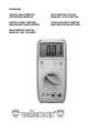
DVM990BL
DIGITAL MULTIMETER
OPERATING MANUAL
MULTIMETRE DIGITAL
MANUEL D’UTILISATION
DIGITALE MULTIMETER
BEDIENINGSHANDLEIDING
DIGITALES MULTIMETER
BEDIENUNGSANLEITUNG
MULTÍMETRO DÍGITAL
MANUAL DEL USUARIO
1.
SAFETY INFORMATION
WARNING
To ensure safe operation, and in order to exploit to the full functionality of the
meter, please follow the directions in this section carefully.
This multimeter has been designed according to IEC-1010 for electronic
measuring instruments, with an overvoltage category CAT II and pollution
category 2.
Follow all safety and operating instructions to ensure that the meter is used
safely and is kept in good operating condition.
1.1.
PRELIMINARY
1.1.1. When using the meter, the user must observe all normal safety rules
concerning:
• protection against the dangers of electric current
• protection of the meter against misuse
1.1.2. When the meter is delivered, check that it has not been damaged in
transit.
1.1.3. If in a poor condition due to harsh storage or shipping conditions,
immediately inspect the meter and confirm its condition.
1.1.4. Test leads must be in good condition. Before using check that the test
lead insulation is not damaged and/or the lead wire is not exposed.
1.1.5. Full compliance with safety standards can only be guaranteed if used
with the test leads supplied. If necessary, they must be replaced with
leads of the same type with the same electric ratings.
1.2. DURING USE
1.2.1. Never exceed the protection limit values indicated in the specifications
for each measurement range.
1.2.2. When the meter is connected to a circuit under measurement, do not
touch unused terminals.
1.2.3. If the value to be measured is unknown beforehand, set the range
selector to the highest position.
1.2.4. Do not measure voltage if the voltage on the terminals exceeds 1000V
above earth.
1.2.5. Always be careful when working with voltages above 60V DC or 30V
AC rms, keep your fingers behind the probe barriers while measuring.
DVM990BL
1
VELLEMAN
1.2.6. Before rotating the range selector to change functions, disconnect the
test leads from the circuit under test.
1.2.7. Never connect the meter leads across a voltage source while the
function switch is in the current, resistance, diode or continuity mode.
Doing so can damage the meter. When doing measurements on TV or
power switching circuits always remember that there may be high
amplitude voltage pulses at test points which can damage the meter.
1.2.9. Never perform resistance measurements on live circuits.
1.2.10. Never perform capacitance measurements unless the capacitor to be
measured has been fully discharged.
1.2.11. If any faults or abnormalities are observed, the meter should not be
used and it needs to be inspected.
1.2.12. Never use the meter unless the back of the casing is in place and
fastened securely.
1.2.13. Do not store or use the meter in areas exposed to direct sunlight, high
temperature, humidity or condensation.
1.3.
SYMBOLS
Important safety information, refer to the operating manual.
Dangerous voltage may be present.
Double insulation (Protection Class II)
Earth
1.4.
MAINTENANCE
1.4.1. Do not attempt to adjust or repair the meter by removing the back of
the casing while voltage is applied. Only a technician who fully
understands the danger involved should carry out such operations.
1.4.2. Before opening the meter battery cover, always disconnect the test
leads from all sources of electric current.
1.4.3. For continued protection, only replace the fuse with the specified
voltage and current ratings:
F1: F 200mA/250V (quick acting)
F2: F 10A/250V (quick acting)
1.4.4. Do not use abrasives or solvents on the meter, use a damp cloth and
mild detergent only.
1.4.5. Always set the power switch to the OFF position when the meter is not
in use.
1.4.6. If the meter is to be stored for a long period of time, the batteries
should be removed to prevent damage to the unit.
DVM990BL
2
VELLEMAN
2.
DESCRIPTION
2.1.
NAMES OF COMPONENTS
(1)
(2)
(3)
(4)
(5)
(6)
(7)
(8)
(9)
(10)
DVM990BL
LCD display
Power switch (POWER)
Black light switch (
)
Data hold switch (H)
Rotary switch
Input socket
Case
Battery door
Brace
Screw
3
VELLEMAN
2.2. FUNCTION AND RANGE SELECTOR
-
3.
This meter is a portable professional measuring instrument with a large
LCD and back light for easy reading.
This meter has built-in protection to prevent the test leads being
connected incorrectly. The input socket for the red test lead senses the
correct functions and ranges. When the rotary switch cannot be turned,
do not force it as it means that the selected range isn’t suitable for what
the red lead is connected to. Pull out the red lead and then select the
required range. This provides protection for the meter in order to avoid
damage through incorrect operation.
This meter has a data hold function.
A rotary switch is used to select the functions and the ranges.
SPECIFICATIONS
Accuracy is specified for a period of one year after calibration and at
18°C to 28°C (64°F to 82°F) with relative humidity to 75%.
3.1.
•
•
•
•
•
•
•
•
•
•
•
•
•
•
•
•
•
GENERAL SPECIFICATIONS
30 ranges of functions.
Over range protection for all ranges.
Operating altitude: 2000m max.
Max. voltage between terminals and earth: 1000V DC or AC (peak
value)
Fuse protection: F1 200mA/250V F2 10A/250V
Display: 28mm LCD, word is 28mm high
Max display value: 1999 (3 1/2)
Polarity indication: "-" indicates negative polarity
Over range indication: displays "1" or "-1"
Sampling time: approx. 0.4 seconds
Power supply: 9V battery, 6F22 or NEDA 1604
" displayed
Low battery indication: "
Temperature factor: < 0.1 x accuracy / °C
Operating temperature: 0°C to 40°C (32°F to 104°F)
Storage temperature: -10°C to 50°C (10°F to 122°F)
Dimensions: 191 x 82 x 36mm (without holster)
Weight: approx. 280g (including battery)
DVM990BL
4
VELLEMAN
3.2.
ELECTRICAL SPECIFICATIONS
Ambient temperature: 23 ± 5°C
Relative humidity: < 70%
3.2.1. DC Voltage
Range
Resolution
Accuracy (% reading + digits)
200mV
0.1mV
± (0.5% of rdg + 1 digit)
2V
1mV
± (0.5% of rdg + 3 digits)
20V
10mV
± (0.5% of rdg + 3 digits)
200V
100mV
± (0.5% of rdg + 3 digits)
1000V
1V
± (0.8% of rdg + 3 digits)
Input impedance: 10 Mohm
Overload protection: 200mV range: 250V DC or rms AC
2V-1000V ranges: 1000V DC or 700V rms AC
NOTE:
At low voltage range, the meter will show an unsteady reading when
the test leads are not connected to the circuit. This is normal because
the meter is very sensitive. When the test leads touch the circuit, you
get the true reading.
3.2.21.
AC Voltage
Range
Resolution
Accuracy (% reading + digits)
200mV
0.1mV
± (1.2% of rdg + 5 digits)
2V
1mV
± (1.0% of rdg + 5 digits)
20V
10mV
± (1.0% of rdg + 5 digits)
200V
100mV
± (1.0% of rdg + 5 digits)
1000V
1V
± (1.2% of rdg + 5 digits)
Input impedance: 10 Mohm
Overload protection: 200mV range: 250V DC or rms AC
2V-1000V ranges: 1000V DC or 700V rms AC
Frequency range: 40 to 400Hz
Test on 60Hz/50Hz
Response: average, calibrated in rms of sine wave
NOTE:
At low voltage range, the meter will show an unsteady reading when
the test leads are not connected to the circuit. This is normal because
the meter is very sensitive. When the test leads touch the circuit, you
get the true reading.
DVM990BL
5
VELLEMAN
3.2.3. DC Current
Range
Resolution
Accuracy (% reading + digits)
2mA
1µA
± (1.0% of rdg + 3 digits)
20mA
10µA
± (1.0% of rdg + 3 digits)
200mA
100µA
± (1.5% of rdg + 5 digits)
10A
10mA
± (2.0% of rdg + 10 digits)
Overload protection: 2mA to 200mA ranges: F1: F 200mA/250V fuse
10A range: F2: F 10A / 250V fuse
Max. input current: mA socket: 200mA
10A socket: 10A (less than 15 seconds)
Voltage drop: 200mV
3.2.4. AC Current
Range
Resolution
Accuracy (% reading + digits)
2mA
1µA
± (1.2% of rdg + 5 digits)
20mA
100µA
± (2.0% of rdg + 5 digits)
10A
10mA
± (3.0% of rdg + 10 digits)
Overload protection: 2mA to 200mA ranges: F1: F 200mA/250V fuse
10A range: F2: F 10A / 250V fuse
Max. input current: mA socket: 200mA
10A socket: 10A (less than 15 seconds)
Voltage drop: 200mV (full range)
Frequency range: 40 to 400Hz
Test on 60Hz/50Hz
Response: average, calibrated in rms of sine wave
3.2.5. Resistance
Range
200ohm
2kohm
20kohm
200kohm
2Mohm
20Mohm
200Mohm
Accuracy (% reading + digits)
± (1.0% of rdg + 10 digits)
± (1.0% of rdg + 1 digit)
± (1.0% of rdg + 1 digit)
± (1.0% of rdg + 1 digit)
± (1.0% of rdg + 1 digit)
± (1.0% of rdg + 5 digits)
± (5.0% of (rdg - 10 digits) + 20
digits)
Open Circuit Voltage: 200 Mohm range: 3V
Other ranges: less than 700mV
Overload protection: 250V DC or rms AC
DVM990BL
Resolution
0.1ohm
1ohm
10ohm
100ohm
1kohm
10kohm
100kohm
6
VELLEMAN
NOTE:
With the 200 Mohm range, if the input is short circuited, the display will
read 1Mohm. This 1Mohm should be subtracted from the measured
results.
3.2.6. Capacitance
Range
Resolution
Accuracy (% reading + digits)
2nF
1pF
± (4.0% of rdg + 3 digits)
20nF
10pF
± (4.0% of rdg + 3 digits)
200nF
0.1nF
± (4.0% of rdg + 3 digits)
2µF
1nF
± (4.0% of rdg + 3 digits)
20µF
10nF
± (4.0% of rdg + 3 digits)
Overload Protection: 250V DC or rms AC
3.2.7. Diode
Range
Resolution
1mV
Function
Display: reads approximate
forward voltage of diode
Overload Protection: 250V DC or rms AC
Forward DC current: approximate 1mA
Reverse DC voltage: approximate 2.8V
3.2.6. Continuity
Range
Function
Built-in buzzer will sound, if resistance is less
than 70 ohms
Overload Protection: 250V DC or rms AC
Open circuit voltage: approximate 2.8V
3.2.9. Frequency
Range
Resolution
Accuracy (% reading + digits)
20kHz
10Hz
± (1.5% of rdg + 10 digits)
Overload Protection: 250V DC or rms AC
Sensitivity: 200mV rms and input no more 10V rms
DVM990BL
7
VELLEMAN
3.2.10. Temperature
Range
Resolutio
n
Accuracy (% reading + digits)
-20°C
-20°C to 0°C
± (5.0% of rdg + 5 digits)
to
1°C
0°C to 400°C
± (1.0% of rdg + 3 digits)
1000°C
400°C to 1000°C ± (2.0% of rdg + 3 digits)
Overload Protection: 250V DC or rms AC
4.
OPERATING INSTRUCTIONS
4.1.
DATA HOLD
If you want data hold when measuring, press "H" and it will hold the
reading. Press the button again to remove data hold.
4.2.
BACK LIGHT
In poor lighting conditions, press "
reading easier.
" to put the back light on to make
NOTE:
1.
An LED is the main back light source. Its operating current is large,
although the meter has a timer (the time is 5 seconds and it will switch
off automatically after 5 seconds). Frequent use of the back light will
shorten the battery life. It is better not to use the back light when not
necessary.
".
2.
When the battery voltage is less than 7V, it will display "
However, when using the back light at the same time, "
" may
appear even if the battery voltage is more than 7V, because the
operating current is higher and the voltage will fall. You do not need to
"
replace the battery if this happens. In normal use (back light off), "
will not appear if the battery is good.
4.3.
PREPARATION FOR MEASUREMENT
4.3.1. Switch on with the "POWER" switch. If the battery voltage is less than
" will appear and the battery should be replaced.
7V, "
4.3.2. The " " next to the input socket means that the input voltage or
current should be less than that specified on the meter sticker in order
to protect the interior circuit from damage.
4.3.3. Select the appropriate range for the item to be measured with the
rotary switch.
DVM990BL
8
VELLEMAN
4.4.
MEASURING VOLTAGE
4.4.1. Connect the black test lead to the COM socket and the red test lead to
the V/Ω socket.
4.4.2. Set the rotary switch to the desired V
or V range.
4.4.3. Connect the test leads across the source or load under test.
4.4.4. You can see the reading on the LCD. The polarity of the red lead will
be indicated along with the voltage value when making DC voltage
measurements.
NOTE:
1.
When only the figure "1" or "-1" is displayed, it indicates an over range
situation and a higher range has to be selected.
2.
When the value to be measured is unknown beforehand, set the range
selector to the highest position.
3.
" " means you cannot have a voltage input that is higher than 1000V
DC or 7000V rms AC. It is possible to display a higher voltage, but it
may destroy the interior circuit.
4.
Be careful to avoid electric shocks when measuring high voltages.
4.5.
MEASURING CURRENT
4.5.1. Connect the black test lead to the COM socket and the red test lead to
the mA socket for a maximum of 200mA current. For a maximum of
10A, move the red lead to the 10A socket.
4.5.2. Set the rotary switch to the desired A
or A range.
4.5.3. Connect the test leads in series with the load under test.
4.5.4. You can see the reading on the LCD. The polarity of the red lead will
be indicated along with the current value when making DC current
measurements.
NOTE:
1.
When only the figure "1" or "-1" is displayed, it indicates an over range
situation and a higher range has to be selected.
2.
When the value to be measured is unknown beforehand, set the range
selector to the highest position.
3.
" " means you cannot input a voltage that is more than 200mA or
10A depending on the socket used. Excess current will blow the fuse.
DVM990BL
9
VELLEMAN
4.6.
MEASURING RESISTANCE
4.6.1. Connect the black test lead to the COM socket and the red test lead to
the V/Ω socket.
4.6.2. Set the rotary switch to the desired Ω range.
4.6.3. Connect the test leads across the resistance under measurement.
4.6.4. You can see the reading on the LCD.
NOTE:
1.
When only the figure "1" is displayed, it indicates an over range
situation and the higher range has to be selected.
2.
When measuring resistance above 1 MΩ, the meter may take a few
seconds to get a stable reading.
3.
When the input is not connected, i.e. an open circuit, the figure "1" will
be displayed for the over range condition.
4.
When measuring in-circuit resistance, be sure that the circuit under
test has all power removed and that all capacitors have been fully
discharged.
5.
At 200 MΩ range, the display reading is around 10 (1 MΩ) when the
test leads are shorted. This has to be subtracted from the measured
results. For example, when measuring 100 MΩ resistance the display
reading will be 101.0 and the correct result should be
101.0 - 1.0 = 100.0 MΩ
4.7.
MEASURING CAPACITANCE
4.7.1. Connect the black test lead to the COM socket and the red test lead to
the V/Ω socket.
4.7.2. Set the rotary switch to the desired F range.
4.7.3. Before inserting capacitors into the capacitance test socket, be sure
that the capacitor has been fully discharged.
4.7.4. You can see the reading on the LCD.
4.7.5. When frequent capacitor testing is required, put the capacitor test unit
plug (spare parts) into COM and V/Ω and put the capacitor leads into
the two long sockets of the capacitor test unit, and capacitor testing is
ready.
WARNING
To avoid electric shock, remove the test leads from the circuit under
test before measuring the capacitance of a capacitor.
DVM990BL
10
VELLEMAN
NOTE:
1.
2.
4.8.
At the low capacitor range, the reading will include the small residual
value of the test leads. It will not influence the accuracy of the
measurement.
It takes time for the reading to become steady when measuring a high
capacitance.
MEASURING TEMPERATURE
4.8.1. Set the rotary switch to the °C position.
4.8.2. The 'LCD' display will show the current ambient temperature.
4.8.3. To measure temperature with a thermocouple, the temperature probe
for this meter can be used. Insert the "K" type thermocouple into the
temperature measuring socket on the front panel and bring the
thermocouple probe into contact with the object to be measured.
4.8.4. You can see the reading on the LCD.
4.9.
MEASURING FREQUENCY
4.9.1. Connect the black test lead to the COM socket and the red test lead to
the V/Ω socket.
4.9.2. Set the rotary switch to the desired 20kHz range position.
4.9.3. Connect the test leads across the source or load under test.
4.9.4. You can see the reading on the LCD.
NOTE:
1.
2.
Readings can be done at input voltages above 10Vrms, but the
accuracy is not guaranteed.
In noisy environments, it is preferable to use shielded cable to
measure small signals.
4.10. DIODE TEST
4.10.1. Connect the black test lead to the COM socket and the red test lead to
the V/Ω socket. (The polarity of the red lead is "+").
4.10.2. Set the rotary switch to the
position.
4.10.3. Connect the red lead to the anode, and the black lead to the cathode
of the diode under test.
4.10.4. You can see the reading on the LCD.
DVM990BL
11
VELLEMAN
NOTE:
1.
2.
The meter will show the approximate forward voltage drop of the
diode.
If the lead connection is reversed, only the figure "1" will be displayed.
4.11. CONTINUITY TEST
4.11.1. Connect the black test lead to the COM socket and the red test lead to
the V/Ω socket.
4.11.2. Set the rotary switch to the
position.
4.11.3. Connect the test leads across two points of the circuit under test.
4.11.4. If there is continuity (i.e. resistance less than about 70Ω), the built-in
buzzer will sound.
NOTE:
If the input is open circuit, the figure "1" will be displayed.
5.
MAINTENANCE
WARNING
Before attempting to remove the battery door or open the case, be sure
that the test leads have been disconnected from the circuit under test in
order to avoid electric shock hazard.
5.1.
BATTERY REPLACEMENT
5.1.1. If the "
" indicator appears on the LCD display, it indicates that the
battery should be replaced.
5.1.2. Loosen the screw fixing the battery door and remove it.
5.1.3. Replace the dead battery with a new one.
5.1.4. Put back the battery door.
DVM990BL
12
VELLEMAN
5.2.
FUSE REPLACEMENT
WARNING
To avoid electric shock, remove the test leads from the circuit under
test before replacing the fuse. For continued protection, only replace
fuses with specified ratings:
F1: F 200mA/250V F2: F 10A/250V.
5.2.1. Fuses rarely need replacing and almost always blow as a result of
operator error.
5.2.2. Loosen the screw fixing the case and remove it.
5.2.3. Replace the blown fuse with the specified ratings.
5.2.4. Put back the case.
5.3.
TEST LEAD REPLACEMENT
WARNING
Full compliance with safety standards can only be guaranteed if used
with the test leads supplied. If necessary, they must be replaced with
leads of the same type or ones with the same electrical ratings
Electrical ratings of the test leads: 1000V 10A
The test leads must be replaced if bare wire is exposed.
5.4. HOW TO USE THE BRACE
5.4.1. When the meter is not in use: attach the case to the panel face for
safekeeping.@@
5.4.2. When measuring: attach it either to the back of the case or use it as a
stand as illustrated in the cover. It has 3 different positions for easy
reading.
5.4.3. Attach the stand to the top part of the meter and use as a hook for
hanging.
DVM990BL
13
VELLEMAN
6.
ACCESSORIES
6.1.
SUPPLIED WITH THE MULTIMETER
•
•
•
•
•
•
6.2
test leads
9V battery type 6F22 or NEDA 1604
fuse: F1 200mA/250V (Ø5 x 20mm)
fuse: F2 10A/250V (Ø5 x 20mm)
K-type thermocouple
operating manual
OPTIONAL ACCESSORIES
• capacitance test socket
• holster
DVM990BL
14
VELLEMAN