1
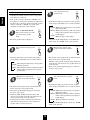
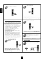
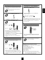
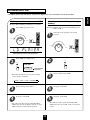
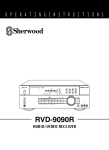
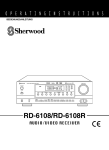
O P E R A T I N G I N S T R U C T I O N S
NEWCASTLE
AUDIO/VIDEO RECEIVER R-945MKII
MASTER VOLUME
OSD
VIDEO LABELS
VCR 1 REC
T.2 MONITOR
STANDBY
MULT I ROOM
REMOTE SENSOR
RF
OPTICAL COAXIAL
VCR1 REC CINEMA BASS
DVD
LDP
AUX
SOURCE
DIGITAL
Pro Logic
POWER
ST
TAPE 2M TUNED AUTO MEMOTY PRESET
INPUT SELECTOR/
INDEX
3 Stereo
DSP THEATER HALL STADIUM
CHURCH
SLEEP
SLEEP
TUNING
FREQ.DIRECT MEMO / ENTER
1
2
3
4
5
6
7
8
9
0
BAND
DIGITAL
INPUTS
DTS
DIGITAL
PRO LOGIC
SURROUND
MODE
FM MODE
- REAR LEVEL +
SPEAKER
MODE
- CENTER LEVEL +
STEREO
FRONT
BASS
PHONES
TREBLE
BALANCE
AUX
SPEAKER
DYNAMIC RANGE CINEMA BASS
ON/
AUX SEL
OFF
-10
10+
-10
10+
LEFT
RIGHT
R-945MKII
AUDIO/VIDEO RECEIVER
S-VIDEO
VIDEO
L _ AUDIO _ R
Introduction
ENGLISH
UNPACKING AND INSTALLATION
Congratulations on Your Purchase!
Your new high fidelity receiver is designed to deliver
maximum enjoyment and years of trouble free service.
Please take a few moments to read this manual
thoroughly. It will explain the features and operation of
your unit and help ensure a trouble free installation.
Please unpack your unit carefully. We recommend that
you save the carton and packing material. They will be
helpful if you ever need to move your unit and may be
required if you ever need to return it for service. Your unit
is designed to be placed in a horizontal position and it is
important to allow at least two inches of space behind
your unit for adequate ventilation and cabling
convenience.
To avoid damage, never place the unit near radiators, in
front of heating vents, in direct sunlight, or in excessively
humid or dusty locations. Connect your complementary
components as illustrated in the following section.
CAUTION
RISK OF ELECTRIC SHOCK
DO NOT OPEN
CAUTION : TO REDUCE THE RISK OF
ELECTRIC SHOCK, DO NOT
REMOVE COVER (OR BACK).
NO USER-SERVICEABLE PARTS
INSIDE. REFER SERVICING TO
QUALIFIED SERVICE PERSONNEL.
This symbol is intended to alert the user to the
presence of uninsulated "dangerous voltage"
within the product's enclosure that may be of
sufficient magnitude to constitute a risk of
electric shock to persons.
This symbol is intended to alert the user to the
presence of important operating and
maintenance (servicing) instructions in the
literature accompanying the appliance.
WARNING
To reduce the risk of fire or electric shock, do not expose
this appliance to rain or moisture.
Caution : Do not block ventilation openings or stack
other equipment on the top.
2
FOR U.S.A.
Note to CATV System Installer: This reminder is
provided to call the CATV system installer's attention
to Article 820-40 of the NEC that provides guidelines
for proper grounding and, in particular, specifies that
the cable ground shall be connected to the
grounding system of the building, as close to the
point of cable entry as practical.
FCC INFORMATION
This equipment has been tested and found to
comply with the limits for a Class B digital device,
pursuant to Part 15 of the FCC Rules. These limits
are designed to provide reasonable protection
against harmful interference in a residential
installation. This equipment generates, uses and can
radiate radio frequency energy and, if not installed
and used in accordance with the instructions, may
cause harmful interference to radio communications.
However, there is no guarantee that interference will
not occur in a particular installation. If this equipment
does cause harmful interference to radio or
television reception, which can be determined by
turning the equipment off and on, the user is
encouraged to try to correct the interference by one
or more of the following measures:
Reorient or relocate the receiving antenna.
Increase the separation between the equipment
and receiver.
Connect the equipment into an outlet on a circuit
different from that to which the receiver is
connected.
Consult the dealer or an experienced radio/TV
technician for help.
CAUTION: Any changes or modifications in
construction of this device which are not expressly
approved by the party responsible for compliance
could void the user's authority to operate the
equipment.
FOR U.S.A. AND CANADA ................................. 120 V
FOR EUROPE AND AUSTRALIA ........ 230 V/240 V
FOR YOUR SAFETY
FOR YOUR SAFETY
Units shipped to the U.S.A. and Canada are designed
for operation on 120 V AC only.
Units shipped to Australia are designed for operation
on 240 V AC only.
To ensure safe operation, the three-pin plug
supplied must be inserted only into a standard threepin power point which is effectively earthed through
the normal household wiring. Extension cords used
with the equipment must be three-core and be
correctly wired to provide connection to earth.
Improper extension cords are a major cause of
fatalities. The fact that the equipment operates
satisfactorily does not imply that the power point is
earthed and that the installation is completely safe.
For your safety, if in any doubt about the effective
earthing of the power point, consult a qualified
electrician.
PAN-EUROPEAN UNIFIED VOLTAGE
All units are suitable for use on supplies 230-240 V
AC.
Safety precaution with use of a polarized AC plug.
However, some products may be supplied with a
nonpolarized plug.
CAUTION : To prevent electric shock, match wide
blade of plug to wide slot, fully insert.
ATTENTION : Pour eviter les choc electriques,
introduire la lame la plug large de la borne
correspondante de la prise et poussre jusqu'au
fond.
CONTENTS
Introduction
UNPACKING AND INSTALLATION ......................................................................................................................... 2
READ THIS BEFORE OPERATING YOUR UNIT ..................................................................................................... 3
System Connections .............................................................................................................................................................. 4
Front Panel Controls ............................................................................................................................................................ 7
Universal Remote Control
DIGI LINK SYSTEM REMOTE CONTROLS ............................................................................................................. 8
OPERATING COMPONENTS WITH REMOTE CONTROL ................................................................................... 10
REMOTE CONTROL OPERATION RANGE ............................................................................................................ 10
LOADING BATTERIES .............................................................................................................................................. 10
ENTERING A SET-UP CODE .................................................................................................................................... 11
Operations
LISTENING TO A PROGRAM SOURCE ................................................................................................................... 12
SURROUND SOUND ...................................................................................................................................................14
ENJOYING SURROUND SOUND ............................................................................................................................. 15
LISTENING TO RADIO BROADCASTS .................................................................................................................. 20
AUDIO RECORDING ................................................................................................................................................. 22
RECORDING WITH VCR 1 ........................................................................................................................................ 23
OTHER FUNCTIONS .................................................................................................................................................. 25
Using the OSD
CURRENT STATUS DISPLAY ................................................................................................................................... 27
MENU SCREEN ........................................................................................................................................................... 28
Troubleshooting Guide ....................................................................................................................................................... 30
Specifications ....................................................................................................................................................................... 31
3
ENGLISH
READ THIS BEFORE OPERATING YOUR UNIT
ENGLISH
System Connections
Do not connect the receiver to the wall AC outlet when plugging and unplugging connection cords.
Be sure to connect the white RCA pin cords to the L (left) and the red RCA pin cords to the R (right) jacks when making
connections.
Change the position of the FM indoor antenna until you get the best reception of your favorite FM stations.
A 75 Ω outdoor FM antenna may be used to further improve the reception.
Disconnect the indoor antenna before replacing it with the outdoor one.
Place the AM loop antenna as far as possible from the receiver, TV set, speaker cords and the AC input cord and set it to a
direction for the best reception.
If the reception is poor with the AM loop antenna, an AM outdoor antenna can be used in place of the AM loop antenna.
Caution: When listening to AM broadcasts in a surround mode without an AM antenna, digital noise can be heard.
Should this happen, connect an AM antenna.
Make connections firmly and correctly. If not, it can cause loss of sound, noise or damage to the receiver.
If the electricity fails or the AC input cord is left unplugged for about 2 weeks, the memorized contents will be cleared.
Should this happen, memorize them again.
■ CONNECTING ANTENNAS
L
R
S E R . NO
ANTENN
FM
DIGITAL
INPUTS
MAIN
IN
AC INPUT
~120V/60Hz
4A
PHONO
AC-3 RF
L
R
S-VIDEO
VIDEO
L
PRE
OUT
MODEL NO. R-945MKII
R
E85649
CENTER
SPEAKER
(8Ω)
29Z3
LISTED
AUDIO EQUIPMENT
AUDIO/VIDEO RECEIVER
PRE
OUT
(OUTDOOR ANTENNA)
NEWCASTLE
DVD
L
AM
LOOP
LDP
C
CENTER
AC-3/PCM
FM
75Ω
TAPE 1
PLAY
L
Manufactured under license from Dolby
FRONT
Laboratories. "Dolby", "PRO LOGIC" and
SPEAKERS
(8Ω)
the double-D symbol are trademarks of
Dolby Laboratories. Confidential Unpublished
Works. '1992-1997 Dolby Laboratories, Inc.
All rights reserved.
PLAY
OPTICAL
REAR
PRE
OUT
VCR
TAPE 1
REC
REC
TAPE 2
PLAY
TV
C
MADE IN KOREA
DESIGNED IN USA
COAXIAL
SUB
WOOFER
R
L
AC OUTLETS
REAR
SPEAKERS
(8Ω)
R
R
L
GND
MULTI
ROOM
TAPE 2
REC
L
T h i s d evice complies with Part 15 of the FCC Rules.
Operation is subject to the following two conditions:
(1)This device may not cause harmful interference, and
(2)this device must accept any interference received,
including interference that may cause undesired operation.
FM
DIGI-LINK
VIDEO MONITOR
C AUTION
SWITCHED
~~120V/60Hz
TOTAL 100W
1A MAX
RISK OF ELECTRIC SHOCK
D O N O T OPEN
W ARNING:"SHOCK HAZARDDO NOT OPEN"
AVIS:"RISQUE DE CHOCELECTRIQUE-NE PAS OUVRIR"
■ CONNECTING VIDEO COMPONENTS
AM loop antenna
(INDOOR ANTENNA)
R
"Manufactured under license from Digital Theater Systems, Inc. US Pat. No.5,451,942 and ather world-wide
patents issues and pending. "DTS", "DTS Digital surround", are trademarks of Digital Theater systems, Inc.
Copyright 1996 Digital Theater System, Inc. All Rights Reserved.
Video deck 1
AUDIO IN
POWER
S-VIDEO IN
MULTIPLE COMPACT DISC PLAYER CDC-5080R
ON/OFF
V-CD
PBC
GRAPHICS
1
OPEN/CLOSE
2
REVERT
PEAK
3
PROG
AUTO
DELETE
EDIT
4
A
RANDOM
SCENE TRACK
INDEX
B
REPEAT ALL 1 DISC S
A< >B MPX INTRO
STEP
5
1
4
7
10
13
2
3
5
6
8
9
11 12
14 15
PHONES LEVEL
PHONES
MIN
LD player
300 ohm
feeder
AUDIO OUT
AM
LOOP
1
2
3
4
5
S-VIDEO OUT
VIDEO OUT
AUDIO OUT
S-VIDEO OUT
DISC SKIP
MULTIPLE COMPACT DISC PLAYER CDC-5080R
OPEN/CLOSE
PLAY EXCHANGE
Play 1 Exchange 4
POWER
ON/OFF
5 DISC
AUTOMATIC DISC LOADING SYSTEM
PHONES LEVEL
REMOTE SENSOR
V-CD
PBC
GRAPHICS
1
2
REVERT PROG
PEAK
3
4
DELETE
AUTO
EDIT
A
RANDOM REPEAT ALL 1 DISC S
A< >B MPX INTRO
SCENE TRACK
B
INDEX STEP
5
1
4
7
10
13
VIDEO IN
ANTENNA
MAX
PROGRAM/REVIEW RANDOM
REPEAT
MIN
2 3
5 6
8 9
11 12
14 15
MAX
PHONES
VIDEO OUT
DVD player
AUDIO OUT
S-VIDEO OUT
MULTIPLE COMPACT DISC PLAYER CDC-5080R
POWER
ON/OFF
FM
VIDEO OUT
75Ω
SUPPLIED ADAPTOR
L
R
VIDEO
S-VIDEO
DVD
LDP
■ CONNECTING AUDIO COMPONENTS
PLAY
Turntable with MM type cartridge
VCR
CD player
REC
MULTIPLE COMPACT DISC PLAYER CDC-5080R
OPEN/CLOSE
V-CD
PBC REVERT PROG
GRAPHICS
POWER
PEAK
DELETE
ON/OFF
1
2
3
4
AUTO
EDIT
A
B
RANDOM REPEAT ALL 1 DISC S
A< >B MPX INTRO
SCENE TRACK
INDEX STEP
5
1 2 3
4 5 6
7 8 9
10 11 12
13 14 15
PHONES LEVEL
REMOTE SENSOR
PROGRAM/REVIEW RANDOM
REPEAT
MIN
MAX
PHONES
TV
Tape deck 1
DIGI-LINK STEREO DOUBLE CASSETTE DECK DD-5080C
RESET
COUNTER
A/B
MODE
BC
HIGH NORM
CD SYN
M
MPX
MIN
RELAY P
T SIZE
SEC
MEMORY
B/C/OFF
DIGI-LINK
REC
REC
R PLAY
L
dB
-00
-20
-10
-6
-3
0
+3
REVERSE
+6
R
AUTO REVERSE
DUBBING
EJECT
NORMAL
POWER
PHONES
REC LEVEL
0
L
AUTO REVERSE
CD SUN REC
AMS
REC BALAMCE
10
L
R
A
MIC MIX
SOURCE
VIDEO MONITOR
Monitor TV
HX-PRO
RECORD & PLAY/AUTO TAPE SELECTOR
MIC
MIC
R
VIDEO IN
PHONO
O/O
HIGH
AMS
B
S-VIDEO IN
PLAY/AUTO TAPE SELECTOR
PLAY(LINE OUT)
R
L
REC(LINE IN)
CD
*Tape deck 2 or graphic equalizer
TAPE 1
PLAY
DIGI-LINK STEREO DOUBLE CASSETTE DECK DD-5080C
RESET
COUNTER
A/B
MODE
BC
HIGH NORM
CD SYN
M
MPX
MIN
RELAY P
T SIZE
SEC
MEMORY
REVERSE
R PLAY
-00
B/C/OFF
REC
REC
L
dB
-20
-10
-6
-3
0
+3
+6
R
AUTO REVERSE
TAPE 1
REC
EJECT
DUBBING
NORMAL
PLAY/AUTO TAPE SELECTOR
O/O
POWER
GND
AMS
PHONES
REC LEVEL
0
TAPE 2
PLAY
AUTO REVERSE
CD SUN REC
HIGH
AMS
B
10
REC BALAMCE
L
R
A
MIC MIX
SOURCE
HX-PRO
RECORD & PLAY/AUTO TAPE SELECTOR
MIC
AUDIO OUT
MIC
VIDEO OUT
* The TV jacks may also be connected to an additional video
component such as a cable TV tuner, a video deck or satellite
system.
* Use the S-VIDEO jacks to make connections to video
components with S-VIDEO IN/OUT jacks. A signal input into the
S-VIDEO jack will be output in only the S-VIDEO jack and a
signal input into the normal VIDEO jack will be output in only the
normal VIDEO jack.
PLAY(LINE OUT)
TAPE 2
REC
L
R
*TV or additional video component
S-VIDEO OUT
REC(LINE IN)
* The TAPE 2 MONITOR PLAY/REC jacks may also be connected to
the LINE OUT/IN jacks of an optional graphic equalizer.
4
■ CONNECTING MULTI-ROOM ADAPTOR
R
S E R . NO
ANTENN
DIGITAL
INPUTS
MAIN
IN
AC INPUT
~120V/60Hz
4A
PHONO
AC-3 RF
L
R
VIDEO
S-VIDEO
L
PRE
OUT
OUT
MULTI
ROOM
AC-3/PCM
VCR
REC
C
R
L
AC OUTLETS
REAR
SPEAKERS
(8Ω)
R
TAPE 2
PLAY
TV
R
L
GND
MULTI
ROOM
TAPE 2
REC
T hi s device complies with Part 15 of the FCC Rules.
Operation is subject to the following two conditions:
(1)This device may not cause harmful interference, and
(2)this device must accept any interference received,
including interference that may cause undesired operation.
■ CONNECTING DIGITAL INPUTS
Component with
COAXIAL DIGITAL OUT
29Z3
LISTED
AUDIO EQUIPMENT
Manufactured under license from Dolby
FRONT
Laboratories. "Dolby", "PRO LOGIC" and
SPEAKERS
(8Ω)
the double-D symbol are trademarks of
Dolby Laboratories. Confidential Unpublished
Works. '1992-1997 Dolby Laboratories, Inc.
All rights reserved.
PLAY
TAPE 1
REC
L
COAXIAL
TAPE 1
PLAY
OPTICAL
REAR
PRE
OUT
AC-3 RF
E85649
CENTER
SPEAKER
(8Ω)
MADE IN KOREA
DESIGNED IN USA
COAXIAL
SUB
WOOFER
FM
75Ω
LD player with AC-3
DIGITAL RF OUT
LDP
C
CENTER
DIGITAL
INPUTS
MODEL NO. R-945MKII
R
AUDIO/VIDEO RECEIVER
PRE
OUT
• Connect this jack to the output of the multi-room adaptor.
For information on the multi-room adaptor, contact the
Xantech corporation at 1-800-843-5465.
NEWCASTLE
DVD
L
AM
LOOP
L
R
DIGI-LINK
VIDEO MONITOR
W ARNING:"SHOCK HAZARDDO NOT OPEN"
AVIS:"RISQUE DE CHOCELECTRIQUE-NE PAS OUVRIR"
C AUTION
"Manufactured under license from Digital Theater Systems, Inc. US Pat. No.5,451,942 and ather world-wide
patents issues and pending. "DTS", "DTS Digital surround", are trademarks of Digital Theater systems, Inc.
Copyright 1996 Digital Theater System, Inc. All Rights Reserved.
SWITCHED
~~120V/60Hz
TOTAL 100W
1A MAX
RISK OF ELECTRIC SHOCK
D O N O T OPEN
■ CONNECTING SPEAKERS
Front right
Front left
Center
AC-3/PCM
OPTICAL
Component with
OPTICAL DIGITAL OUT
• A digital input should be connected to the components such as
LD player or DVD, etc. capable of outputing DTS Digital
Surround, Dolby Digital(AC-3), PCM or RF format digital signals.
• For details, refer to the operating instructions of the
component connected.
• When making the COAXIAL DIGITAL connection, be sure to
use a 75Ω COAXIAL cord, not a conventional AUDIO cord.
CENTER
SPEAKER
(8Ω)
FRONT
SPEAKERS
(8Ω)
■ CONNECTING SYSTEM CONTROL
-
+
R
+
REAR
SPEAKERS
(8Ω)
L
R
-
+
L
Sherwood component
with DIGI LINK II or III
CD player
Tape deck
System
control
cord
DIGI-LINK
Rear right
Graphic equalizer
Rear left
• Never short circuit the + and – speaker cords.
• Be sure to connect speakers firmly and correctly
according to the channel (left and right) and the polarity
(+ and –).
• Be sure to use the speakers with the impedance of over
8 Ω.
• Always connect both rear speakers.
• For installing the speakers, refer to "Speaker placement"
on page 15.
• Connect this jack to the DIGI LINK jack of the external
Sherwood component that uses the DIGI LINK II or III remote
control system.
5
ENGLISH
L
Adaptor
■ AC INPUT CORD
ENGLISH
■ MAIN IN connections
L
Pre amplifier
R
Plug this cord into a wall AC outlet
MAIN
IN
PRE
OUT
PRE
OUT
SUB
WOOFER
CENTER
L
R
SER. NO
ANTENN
DIGITAL
INPUTS
MAIN
IN
AC INPUT
~120V/60Hz
4A
PHONO
AC-3 RF
L
R
VIDEO
S-VIDEO
L
• When a separate pre amplifier is used for front channels,
connect these jacks to the pre amplifier and connect the front
speakers to this receiver.
PRE
OUT
NEWCASTLE
DVD
L
AM
LOOP
MODEL NO. R-945MKII
R
E85649
CENTER
SPEAKER
(8Ω)
29Z3
LISTED
AUDIO EQUIPMENT
AUDIO/VIDEO RECEIVER
PRE
OUT
LDP
C
CENTER
AC-3/PCM
FM
75Ω
TAPE 1
PLAY
L
Manufactured under license from Dolby
FRONT
Laboratories. "Dolby", "PRO LOGIC" and
SPEAKERS
(8Ω)
the double-D symbol are trademarks of
Dolby Laboratories. Confidential Unpublished
Works. '1992-1997 Dolby Laboratories, Inc.
All rights reserved.
PLAY
OPTICAL
REAR
PRE
OUT
VCR
TAPE 1
REC
REC
TAPE 2
PLAY
TV
C
MADE IN KOREA
DESIGNED IN USA
COAXIAL
SUB
WOOFER
R
L
AC OUTLETS
REAR
SPEAKERS
(8Ω)
R
R
L
GND
MULTI
ROOM
TAPE 2
REC
T h i s d evice complies with Part 15 of the FCC Rules.
Operation is subject to the following two conditions:
(1)This device may not cause harmful interference, and
(2)this device must accept any interference received,
including interference that may cause undesired operation.
L
■ PRE OUT connections
DIGI-LINK
VIDEO MONITOR
C AUTION
SWITCHED
~~120V/60Hz
TOTAL 100W
1A MAX
RISK OF ELECTRIC SHOCK
D O N O T OPEN
■ SWITCHED AC OUTLETS
Front speakers
L
R
"Manufactured under license from Digital Theater Systems, Inc. US Pat. No.5,451,942 and ather world-wide
patents issues and pending. "DTS", "DTS Digital surround", are trademarks of Digital Theater systems, Inc.
Copyright 1996 Digital Theater System, Inc. All Rights Reserved.
W ARNING:"SHOCK HAZARDDO NOT OPEN"
AVIS:"RISQUE DE CHOCELECTRIQUE-NE PAS OUVRIR"
R
• These outlets are switched on and
off by the POWER button on the
front panel or on the remote control.
(Maximum total capacity is 1 A,
100W)
Power amplifier
Standby mode – switched AC outlet off
Power on mode – switched AC outlet on
MAIN
IN
PRE
OUT
PRE
OUT
CENTER
SUB
WOOFER
REAR
PRE
OUT
Power amplifier
L
Center speaker
Powered
subwoofer
R
Power amplifier
Rear speakers
• Use these jacks when adding additional amplifiers.
• Connect the PRE OUT jacks to the powered speakers or the power amplifiers
connected to speakers respectively.
• To emphasize the deep bass sounds, connect a powered subwoofer.
• When you do not use the front MAIN IN and PRE OUT jacks, always connect these
jacks with the supplied jumper plugs.
6
OSD BUTTON/INDICATOR
VIDEO LABELS BUTTON
VCR1 REC SELECTOR BUTTON
TAPE2 MONITOR BUTTON
INPUT SELECTOR / INDEX KNOB
MASTER VOLUME CONTROL KNOB
POWER BUTTON
SLEEP BUTTON
REMOTE SENSOR
STANDBY INDICATOR
DIGITAL INPUT INDICATORS
AUDIO/VIDEO RECEIVER R-945MKII
MASTER VOLUME
OSD
VIDEO LABELS
VCR 1 REC
T.2 MONITOR
STANDBY
MULT I ROOM
REMOTE SENSOR
RF
OPTICAL COAXIAL
VCR1 REC CINEMA BASS
DVD
LDP
AUX
SOURCE
DIGITAL
Pro Logic
POWER
ST
TAPE 2M TUNED AUTO MEMOTY PRESET
INPUT SELECTOR/
INDEX
3 Stereo
DSP THEATER HALL STADIUM
CHURCH
SLEEP
SLEEP
TUNING
FREQ.DIRECT MEMO / ENTER
1
2
3
4
5
6
7
8
9
0
FM MODE
BAND
DIGITAL
INPUTS
DIGITAL
DTS
PRO LOGIC
SURROUND
MODE
- REAR LEVEL +
SPEAKER
MODE
- CENTER LEVEL +
STEREO
FRONT
BASS
PHONES
TREBLE
BALANCE
AUX
SPEAKER
AUX SEL
DYNAMIC RANGE CINEMA BASS
ON/
OFF
-10
HEADPHONE JACK
10+
-10
10+
LEFT
RIGHT
S-VIDEO
VIDEO
L _ AUDIO _ R
CINEMA
FRONT AUX/
BASS
REAR TV SELECTOR BUTTON/INDICATOR
BUTTON
CENTER LEVEL UP/DOWN (+/ -) BUTTONS
DYNAMIC
BALANCE
CONTROL
KNOB
RANGE
SPEAKER MODE BUTTON
BUTTON/
TUNING UP/DOWN
INDICATOR
( / ) BUTTONS
SURROUND MODE
BUTTON
TREBLE CONTROL KNOB
REAR LEVEL UP/DOWN (+/ -) BUTTONS
DOLBY( )
MEMORY/ ENTER BUTTON
PRO LOGIC BUTTON
DOLBY( ) DIGITAL BUTTON
FM MODE BUTTON
DTS BUTTON/INDICATOR
BASS CONTROL KNOB
DIGITAL INPUT BUTTON
BAND BUTTON
SPEAKER ON/OFF SWITCH
FREQUENCY DIRECT BUTTON
NUMERIC BUTTONS
STEREO BUTTON
■ Front AUX INPUT JACKS
■ FLUORESCENT DISPLAY
INPUT, FREQUENCY,PRESET, VOLUME LEVEL, OPERATING INFORMATIONS, etc
STEREO INDICATOR
TAPE 2 MONITOR INDICATOR
TUNED INDICATOR
AUTO INDICATOR
VCR1 RECORD SOURCE DISPLAY
MEMORY INDICATOR
CINEMA BASS INDICATOR
PRESET INDICATOR
VCR1 REC CINEMA BASS
DVD
LDP
AUX
SOURCE
DIGITAL
Pro Logic
RDS
ST
3 Stereo
DSP
THEATER
TAPE 2M TUNED AUTO MEMOTY PRESET
HALL
STADIUM
CHURCH
AUX
_
S VIDEO
VIDEO
L _ AUDIO _ R
Additional video component
S _ VIDEO OUT
AUDIO OUT
VIDEO OUT
SLEEP
SLEEP INDICATOR
CHURCH INDICATOR
STADIUM INDICATOR
HALL INDICATOR
THEATER INDICATOR
3 Stereo INDICATOR
Pro Logic INDICATOR
DIGITAL INDICATOR
7
The front AUX input jacks may be also connected to an
additional video component such as a camcorder, a video
deck or a video game player, etc.
Use the S-VIDEO jack to make connection to video
component with the S-VIDEO OUT jack.
A signal input into the S-VIDEO jack will be output in only
the S-VIDEO jack and a signal input into the normal
VIDEO jack will be output in only the normal VIDEO jack.
ENGLISH
Front Panel Controls
ENGLISH
Universal Remote Control
Note: For enhanced Universal Remote Programming instructions and product identification codes, please refer to the operating
manual inclosed with this Universal Remote Control.
This remote control has 3 operating modes as follows;
OSD (On Screen Display) mode: Allows you to look at information about basic operation of this receiver on your monitor TV
and to operate this receiver by moving an arrow that appears on the screen of your monitor TV.
Sherwood mode: Allows you to operate this receiver, and other Sherwood components like cassette decks, CD players and
equalizers, etc. (To operate other Sherwood components, you should make the DIGI LINK connections
between them)
Non-Sherwood mode: Allows you to operate the non-Sherwood audio and video components.
Notes:
The set-up code for each component should be entered before operation.
For set-up codes(product identification codes), please refer to “Set-Up Code Tables” in the operating manual of this remote
control.
Some operation buttons have different functions according to each operation mode.
Be sure to set the remote control to the correct mode before operation.
DIGI LINK SYSTEM REMOTE CONTROLS
This section explains the basic functions for Sherwood or OSD mode. For non-Sherwood mode, refer to the operating manual of
this remote control.
All Sherwood components bearing the DIGI LINK (II or III) logo can be used with this remote control.
For system remote control operation, first make the DIGI LINK connections between Sherwood components.
The numbered buttons on the remote control have different functions in different modes. For details, refer to the “FUNCTION
TABLE of the NUMBERED BUTTONS” on next page.
LIQUID CRYSTAL DISPLAY
LED LAMP
DEVICE BUTTONS
To operate the desired component with this remote
control, first select the corresponding DEVICE button
VOLUME
/
POWER BUTTON
(UP/DOWN)BUTTONS
MUTE BUTTON
TAPE
PRESET SCAN BUTTON
7
1
3
2
5
6
8
9
NUMERIC(1~0)/CURSOR CONTROL( , , , )BUTTONS
For selecting preset stations or entering frequency directly in tuner mode.
For selecting a track or a disc in CD mode.
When selecting a disc, select disc No. (1~5)within 2
sec. after pressing DISC button.
For moving an arrow with the CURSOR CONTROL buttons
in the OSD mode.
DISC BUTTON (CD CHANGER Only)
INPUT SELECTOR BUTTONS
In the standby mode, when pressing a input
selector button, the receiver is turned on automatically
and the desired input source is selected.
4
SLEEP BUTTON
SYSTEM DISPLAY BUTTON
OSD BUTTON
TEST TONE BUTTON
ENTER BUTTON
EQUALIZER FUNCTIONS
T.MON-for monitoring the sound of recording or
(EQ.T) playback on tape deck
DISPLAY-for selecting equalizer display.
USER-for adjusting equalizer pattern as desired.
PRESET-for selecting equalizer pattern.
FILE-for selecting desired equalizer pattern in the
preset or in the user mode.
LIGHT BUTTON
activates the backlighting of the remote control
for 5 sec. If any other button is pressed while
the backlighting is on, the reomote control will
remain backlit for an additional 5 sec.
8
Component control
selection buttons
(for receiver)
(for CD player)
(for tape deck)
Button symbols
①
SUBWOOFER LEVEL
DOWN
REPEAT A<·>B
DECK SELECTOR A
②
SUBWOOFER LEVEL UP
INTRO SCAN
DECK SELECTOR B
③
CENTER LEVEL UP
PAUSE
PAUSE
④
CENTER LEVEL DOWN
STOP
STOP
⑤
REAR LEVEL DOWN
BACKWARD SKIP
REWIND
⑥
REAR LEVEL UP
FORWARD SKIP
FAST-FORWARD
⑦
SURROUND MODE
PLAY
FORWARD PLAY
⑧
DELAY TIME
─
REVERSE PLAY
⑨
DELAY ADJUST
─
RECORD
When using the Sherwood DIGI LINKⅢ components, by pressing PLAY, etc. on CD player or tape deck, CD or TAPE 2
MONITOR is selected automatically without selecting the input source and then PLAY, etc. starts.
In this case, to listen to TAPE 1, switch off the TAPE 2 MONITOR and select the TAPE 1.
Notes:
Some functions for CD player, tape deck or equalizer may not be available.
For details about functions, refer to the operating instructions of each component.
The TV/OFF and the CH ∨ buttons may not be available for this receiver.
9
ENGLISH
FUNCTION TABLE of the NUMBERED BUTTONS.
ENGLISH
OPERATING COMPONENTS WITH REMOTE CONTROL
1
2
REMOTE CONTROL OPERATION RANGE
Enter the set-up codes of the components
respectively, referring to “ENTERING A
SET-UP CODE”(page 11).
Use the remote control within a range of about
7 meters (23 feet) and angles of up to 30
degrees aiming at the remote sensor.
Turn on the components you want to
operate.
AUDIO/VIDEO RECEIVER R-945MKII
MASTER VOLUME
OSD
VIDEO LABELS
VCR 1 REC
T.2 MONITOR
STANDBY
MULT I ROOM
REMOTE SENSOR
RF
OPTICAL COAXIAL
VCR1 REC CINEMA BASS
DVD
LDP
VCR 2
SOURCE
AC-3
Pro Logic
POWER
ST
TAPE 2M TUNED AUTO MEMOTY PRESET
INPUT SELECTOR/
INDEX
3 Stereo
DSP THEATER HALL
STADIUM
CHURCH
SLEEP
SLEEP
2
3
4
5
6
7
8
9
0
BAND
3
DIGITAL
INPUTS
Press the DEVICE button on the remote
control corresponding to the component
you want to operate.
DTS
DIGITAL
PRO LOGIC
SURROUND
MODE
FM MODE
- REAR LEVEL +
SPEAKER
MODE
- CENTER LEVEL +
STEREO
FRONT
BASS
PHONES
TREBLE
BALANCE
AUX
SPEAKER
AUX SEL
DYNAMIC RANGE CINEMA BASS
ON/
OFF
-10
10+
-10
10+
LEFT
RIGHT
S-VIDEO
VIDEO
L _ AUDIO _ R
7m
30
4
TUNING
FREQ.DIRECT MEMO / ENTER
1
30
Press the button corresponding to the
operation you want while aiming the
remote control at the REMOTE SENSOR
on the component.
When operating a Sherwood CD player or tape deck
using the system remote control, aim the remote
control at the REMOTE SENSOR on this unit.
LOADING BATTERIES
When “L -BAT” flickers on the LCD, the old batteries should be replaced.
When changing the batteries, load the new batteries within 10 sec. to maintain existing programming
If the batteries are removed for a longer period of time, the remote control might lose its memory and require reentering.
1
Remove the cover.
2
10
Load 4 AAA 1.5V batteries matching the
polarity.
Before operating audio and video components using the remote control supplied with this receiver, the set-up
code for each component should be entered.
For system remote control operation, the set-up code for each Sherwood component such as CD player and
tape deck is “001”respectively. Enter each set-up code for CD player and tape deck doing steps 3,4 and 5 as
follows.
1
Turn on the component you want to control.
2
Example) The 3 digit set-up codes for the Sherwood
“Audio” are 001,002, ...(Hint:The correct setup code for this receiver is “001”.)
Example) When entering the set-up code for this
receiver, turn on this receiver.
3
Find the set-up code for your component
referring to “Set-Up Code Tables” in the
operating manual of this remote control.
Press the corresponding DEVICE and the
MUTE buttons simultaneously.
4
Enter the 3 digit set-up code aiming the remote control
at the REMOTE SENSOR on the component.
For "001" :
0
0
1
For "124" :
1
2
4
For receiver or amplifier :
For CD player
:
For CABLE
:
Your component will be turned off when the correct
set-up code is entered.
Continue to enter the corresponding codes until your
component turns off.
If “SET” disappears, start from the step 3 again.
Then “SET” appears on the LCD of the remote
control for 20 seconds.
5
Operate the component using the
corresponding function buttons on the remote
control such as POWER, CH ∧/∨ and VOL
∧/∨ buttons, etc.
If any of the buttons do not perform as they should,
start from step 1 again to enter the next set-up code.
Notes:Some audio and video components have separate
buttons for POWER ON/OFF.
In this case, press the corresponding DEVICE
button to turn the component ON and press the
POWER button to turn the component OFF.
If there is no correct set-up code or if the
Manufacturer/Brand for your component is not listed
in “Set-Up Code Tables” in the operating manual of
this remote control, please use the “Auto Search
Method” on page 10 in the operating manual of this
remote control.
Although each set-up code is designed to work with
many different modes, certain codes may not work with
some models. (Also, certain codes may only operate
some of the functions available on a given model.)
Press the corresponding DEVICE button to
store the set -up code.
6
For receiver or amplifier :
For CD player
:
For CABLE
:
Then“ PASS”will flicker on the LCD.
7
Repeat the above steps 1 to 6 for each of your other components.
11
ENGLISH
ENTERING A SET-UP CODE
Operations
ENGLISH
Note: Before operating this receiver with the supplied remote control, refer to “Universal Remote Control” on
page 8 for details about operation.
LISTENING TO A PROGRAM SOURCE
1
Turn the power on.
3
POWER
Select the desired input source.
T. 2 MONITOR
INPUT SELECTOR/
INDEX
or
or
or
Each time the INPUT SELECTOR/INDEX knob is
rotated, the input source changes as follows:
→ PHONO ↔ TUNER ↔ CD PLAYER ↔ TAPE 1←
(frequency display)
→ AUX/TV ↔ VCR1 ↔ LD PLAYER ↔ DVD ←
When the TAPE 2 MONITOR button is set to on and
“TAPE 2M” indicator lights up, other inputs can not
be heard from the speakers.
To listen to a input source other than TAPE 2
MONITOR, be sure to set the TAPE 2MONITOR
button to off.
TAPE 2 MONITOR function
You can connect either a tape deck or a graphic
equalizer to the receiver’s TAPE 2 MONITOR jacks.
When listening to the component connected to
these jacks,set the TAPE 2 MONITOR button to on.
If you connect a 3-head tape deck, you can listen to the
sound being recorded during recording, instead of the
source sound.
For further details, refer to the operating instructions
of the component connected.
Each time the POWER button is pressed, the
receiver is turned on to enter the operating mode or
off to enter the standby mode.
In the standby mode, if the INPUT SELECTOR
button is pressed on the remote control, the
receiver is turned on automatically and the desired
input is selected.
In the standby mode, the STANDBY indicator
lights up. This means that the receiver is not
disconnected from the AC outlet and a small
amount of current is retained to support the
memorized contents and operation readiness.
2
Switch the speakers on.
SPEAKER
When the AUX/TV is selected as input source
ON/
OFF
Select the front AUX or the rear TV.
FRONT
AUX SEL
Then sound can be heard from the speakers
connected to the speaker terminals.
When using the headphones for private listening,
press the SPEAKER switch again to switch the
speakers off.
If the front AUX is selected, the FRONT AUX
indicator lights up.
12
7
Select the digital (or the analog) input connected as
desired.
Each time this button is pressed,
DIGITAL
INPUT
the corresponding input is
selected as follows;
–In the DTS mode
OPTICAL COAXIAL
Adjust the stereo balance between the left and
the right channels.
BALANCE
LEFT
8
– In the Dolby Digital(AC-3) mode:Not available for CD
(RF:LDP only) OPTICAL COAXIAL
ENGLISH
When CD, DVD, LDP or AUX/TV is
selected as input source
RIGHT
Adjust the subwoofer level.
To play back the laser disc encoded the Dolby Digital(AC3) format in the Dolby Digital(AC-3) mode, you should
select the RF input as the desired digital input.
– In the normal stereo or a surround mode other than the
DTS and Dolby Digital(AC-3) modes.
OPTICAL COAXIAL
ANALOG
To listen to Dolby Digital program source in the 2-CH
downmix mode, in the stereo mode, the corresponding
digital input (LD Player : RF) should be selected. (For
details, refer to “Downmixing into 2 front channels”
on page 19).
Notes :
When the selected optical or coaxial digital input is not
connected, the selected DIGITAL INPUT indicator is
flickering, meaning no sound.(Refer to “Select the
desired surround mode” on page 15.)
When the DTS or Dolby Digital(AC-3) mode is
selected, the component connected to the selected
digital input can be heard regardless of the selected
input source.
4
5
It is adjustable only when a powered subwoofer is
connected and the subwoofer is set to“YES”. (Refer
to“Adjusting the speaker settings” on page 16 )
9
CINEMA BASS
Press it again to cancel.
Operate the selected component for playback.
10
When playing back the program sources
with surround sound, refer to
“ENJOYING SURROUND SOUND” on
page 15.
To mute the sound.
Adjust the (overall) volume.
“MUTE” will flicker.
To resume the previous sound level, press it again.
MASTER VOLUME
or
DOWN
6
To increase the bass sound.
11
UP
-10
TREBLE
10+
-10
PHONES
Ensure that the SPEAKER ON/OFF
switch is set to off.
When listening to DTS or Dolby Digital(AC-3)
program source in the DTS or the Dolby Digital(AC3) mode, if the headphones are plugged and the
SPEAKER ON/OFF switch is set to off, it enters the
2-CH downmix mode automatically.
(For details, refer to “Downmixing into 2 front
channels” on page 19).
Adjust the tone (bass and treble).
BASS
To listen with the headphones.
10+
Note : Extreme settings at high volume may damage
your speakers.
13
SURROUND SOUND
ENGLISH
This receiver incorporates a sophisticated Digital Signal Processor that allows you to create optimum sound
quality and sound atmosphere in your personal Home Theater.
Surround modes
This receiver has 8 different surround modes to allow you to enjoy surround sound with various program
sources: DTS , DOLBY DIGITAL(AC-3), DOLBY PRO LOGIC, DOLBY 3 STEREO, THEATER,
HALL,STADIUM,CHURCH.
DTS (Digital Theater System) : Allows you to enjoy 5.1 (or 6) discrete channels of high quality digital audio from
DTS program sources bearing the “
”,
“ HDS ” or “HIGH DEFINITION SURROUND” trade mark such as laser discs,
DVD and compact discs, etc. DTS Digital Surround delivers up to 6 channels of
transparent audio (which means identical to the original masters) and results in
exceptional clarity throughout a true 360˚ soundfield.
DTS DIGITAL SURROUND : “DTS” and DTS Digital Surround are trademarks of Digital Theater Systems, Inc.
Note: The DTS program sources should be played back in the DTS mode. If not, no sound or the sound like continuous
noise will be heard.
DOLBY DIGITAL(AC-3) : Allows you to enjoy up to 5.1 channels of digital surround sound from Dolby
Digital(AC-3) program sources bearing the“ D I G I T A L ”trademark such as laser discs.
Dolby Digital(AC-3) provides better sound quality, improved dynamic range and great
sense of direction, compared with the conventional Dolby surround. Now, you are able
to enjoy real Home Theater sound in your home.
DOLBY PRO LOGIC : This receiver incorporates the Dolby Pro Logic Surround Decoder which has the same
functions for playback as movie theaters and gives a theater - like experience in your home,
naturally reproducing the audio sound field. Use with Dolby Pro Logic program sources
DOLBY SURROUND ”
bearing the“
trademark such as video cassette tapes or laser discs.
DOLBY 3 STEREO : Combining the rear speaker signal with that of the front speakers allows you to enjoy a
regenerated sound field which has comparatively more presence and a more expansive feeling
from the 3 front channels (front L,front R and center speakers) than that of ordinary stereo
DOLBY SURROUND ”trademark.
regeneration. Use with Dolby program sources bearing the“
• Manufactured under licence from Dolby Laboratories.
“Dolby”, “ Pro Logic” and the double-D symbol are trademarks of Dolby Laboratories.
Confidential Unpublished Works. 1992-1997 Dolby Laboratories, Inc. All rights reserved.
THEATER : This mode provides the effect of being in a movie theater when watching a movie source that has a
stereo sound track.
HALL : This mode provides the ambience of a concert hall for classical music sources such as orchestral, chamber
music or an instrumental solo.
STADIUM : This mode provides the expansive sound field. For music sources like a rock concert, you will feel as
if you were actually at the live concert. For sports programs such as a baseball game, you can enjoy a
powerful sound, thus obtaining the true stadium effect.
CHURCH: This mode provides the ambience of a church for baroque, string orchestral and choral group music.
Delay time
When the center speaker or the rear speakers is(are) closer to the listener than the front speakers, the sound from the center
speaker or the rear speakers can arrive at the listener’s ear earlier than the sound from the front speakers.
In this case, the imaging is not as sharp and stable as it could be.
For audible improvement, the sound from center speaker can be delayed with the center delay time setting so that the sound
from the front and the center speakers will be heard at the same time and the sound from the rear speakers can be also
delayed with the rear delay time setting so that the sound from the front and the rear speakers will be heard at the same time.
The optimum delay time will be different according to the room size and the acoustic properties. It is recommended that you
try different times to obtain the best effect.
• It is adjustable in the Dolby Digital(AC-3) and the Dolby Pro Logic modes only.(For details, refer to “In Dolby Digital(AC3), Dolby Pro Logic mode, adjusting delay times of the speakers” on page 18.)
14
Speaker placement
TV set
FRONT
LEFT
SUB
WOOFER
FRONT
RIGHT
CENTER
SPEAKER
ENGLISH
To obtain the best surround sound effect in your home, place the speakers as
follows;
Front speakers : Place each front speaker about 1m (40”) from the TV set.
Center speaker : Place the center speaker either above or below the TV set
to assure good visualization of center channel program.
Rear speakers : Place the rear speakers approximately 1m (40”) above the
ear level of a seated listener directly to the left or right of the
main listening position or at the same height but slightly
behind the main position.
Subwoofer : Place the powered subwoofer by a wall or corner of the room
for best sound.
The ideal surround system consists of all the speakers listed above. The
ideal DTS Digital Surround system uses full range speakers for all positions
including both front speakers, both rear speakers and the center speaker.
However, if you don’t have a center speaker, a subwoofer or rear speakers,
select the best possible surround mode with the available speakers.
Note: To avoid interference with the TV picture, use only magnetically
shielded center and front speakers.
REAR
LEFT
REAR
RIGHT
ENJOYING SURROUND SOUND
Surround sound effect will not work properly if the signal passes through a graphic equalizer.
Please refer to your equalizer operating instructions for guidance on switching off (or defeating) the equalizer.
1
Select the desired surround mode.
When selecting a surround mode among the Dolby 3
stereo, Theater, Hall, Stadium and Church modes.
When selecting the DTS mode, the Dolby Digital
(AC-3) mode or the Dolby Pro Logic mode.
DTS
DIGITAL
SURROUND
MODE
or
PRO LOGIC
or
Each time the SURROUND MODE button is pressed,
the surround mode changes as follows;
When the DTS mode is selected, the DTS indicator on
the button lights up.
The DTS mode is available only for DVD,LDP,
AUX/TV and CD as input source.
The Dolby Digital (AC-3) mode is available only for
DVD, LDP and AUX/TV as input source.
To enjoy the DTS mode or the Dolby Digital (AC-3)
mode, be sure that the program source and the
corresponding digital input is selected. If not, no sound
will be heard.
When LDP is selected, the RF digital input will work
only in the Dolby Digital(AC-3) mode.
(Refer to “When CD, DVD, LDP or AUX/TV is
.....selected as input source” on page 13.)
(DTS
(OFF)
DIGITAL
Pro Logic)
CHURCH STADIUM HALL
3 Stereo
THEATER
“( )”: Remote control only.
When canceling the surround mode for normal stereo
operation.
STEREO
15
or
ENGLISH
Adjusting the speaker settings
5
Adjusting the settings of front, center, rear speakers
and subwoofer connected.
If the speaker setting is adjusted to “SMALL”, the
low range bass sound of the channel(s) is redirected to
the subwoofer or the front channels and if the speaker
setting is adjusted to “NONE”, the sound of the
channel(s) is redirected to other channels.
2
Press the SPEAKER MODE
button for more than 2 seconds
to enter the front speaker
mode.
3
↓
LARGE :When using a relatively large center speaker
↓
(full range speaker).
SMALL :When using a relatively small center speaker
SPEAKER
MODE
(which cannot reproduce the low range bass
sounds deeply).
NONE :When not using a center speaker.
↓
Only in the Dolby Digital(AC-3) or the Dolby Pro
Logic mode, the “NONE” mode can be selected.
SPEAKER
MODE
MEMO / ENTER
The desired center speaker mode is memorized and
then it enters the rear speaker mode.
In Dolby 3 Stereo mode, it will enter the subwoofer
mode directly, this means the rear speaker mode can
not be selected.
If the center speaker display disappears, start from
the above step 2 again.
↓
LARGE :When using the relatively large front speakers
(full range speakers).
↓
SMALL :When using the relatively small front speakers
(which cannot reproduce the low range bass
sounds deeply).
4
Memorize the desired center
speaker mode while it flickers.
6
Each time this button is pressed, the front speaker
mode changes and flickers for 5 seconds as follow;
Memorize the desired front
speaker mode while it flickers.
SPEAKER
MODE
Each time this button is pressed, the center speaker
mode changes and flickers for 5 seconds as follows;
The front speaker mode is displayed.
Select the desired front speaker
mode.
Select the desired center
speaker mode.
MEMO / ENTER
Select the desired rear speaker
mode.
7
SPEAKER
MODE
Each time this button is pressed, the rear speaker
mode changes and flickers for 5 seconds as follows;
The desired front speaker mode is memorized and
then it enters the center speaker mode.
If the front speaker display disappears, start from
the above step 2 again.
In Theater, Hall, Stadium, Church mode, it will
enter the rear speaker mode directly, this means the
center speaker mode can not be selected.
In normal stereo mode, it will enter the subwoofer
mode directly, this means the center and the rear
speaker modes can not be selected.
↓
LARGE :When using a relatively large rear speakers.
↓
(full range speakers).
SMALL :When using a relatively small rear speakers.
(which cannat reproduce the low range bass
sounds deeply).
NONE :When not using the rear speakers.
↓
Only in the Dolby Digital(AC-3) mode, the “NONE”
mode can be selected.
16
Checking the speaker setting
MEMO / ENTER
SPEAKER
MODE
ENGLISH
8
Memorize the desired rear
speaker mode while it flickers.
The desired rear speaker mode is memorized and then
it enters the subwoofer mode.
If the rear speaker display disappears, start from the
above step 2 again.
9
Each time this button is pressed briefly, the
corresponding speaker settings are displayed in turn.
Select the desired subwoofer mode.
In DTS, Dolby Digital(AC -3), Dolby Pro
Logic or Dolby 3 Stereo mode
SPEAKER
MODE
11
Press the TEST TONE
button to adjust the volume
level of each speaker.
Each time this button is pressed, the subwoofer
mode changes and flickers for 5 seconds as follows;
YES : When using a subwoofer.
Test tone will be heard form each speaker for 2
seconds each as follows;
NO : When not using a subwoofer.
FRONT L
In case that the front speaker mode is set to
“SMALL”, if the subwoofer mode is set to “NO”,
then the front speaker mode is automatically set to
“LARGE”.
10
CENTER FRONT R REAR R REAR L SUB
The test tone will be heard from the subwoofer only
when subwoofer is set to “YES” in the DTS mode
and the Dolby Digital(AC-3) mode.
Test tone is not heard from rear speakers in Dolby 3
Stereo mode.
Test tone is not heard from the speaker of which the
setting is adjusted to the NONE or the NO mode.
Memorize the desired subwoofer mode
while it flickers.
12
Adjust the volume levels of the speakers
until they all sound equally loud.
or
MEMO / ENTER
- CENTER LEVEL +
- REAR LEVEL +
If the subwoofer display disappears, start from the
above step 2 again.
The rear L and R volume levels are adjusted
respectively during the test tone function and all
together while enjoying surround sounds.
17
15
Adjust the delay time.
ENGLISH
13
Cancel the test tone function.
Each time this button is pressed, the delay time
changes in regular intervals.
If the delay time disappears, start from the step 14 again.
16
In Dolby Digital(AC-3), Dolby Pro Logic
mode, adjusting delay times of the speakers
When the distances from the prime listening
position to front left, center, front right and rear (left
and right) speakers are same, the basic settings are
as follows according to either the Dolby
Digital(AC-3) or the Dolby Pro Logic mode;
- In the Dolby Digital(AC-3) mode.
Center delay time : 0 ms, Rear delay time : 0 ms
- In the Dolby Pro Logic mode.
Rear delay time : 15 ms
If the center or the rear speaker(s) is(are) not at the
same distance from the prime listening position as
the front speakers, increase or decrease the center
delay time by 1 ms for every about 30 cm(1 foot) it
is closer or farther away and increase or decrease the
rear delay time by 5 ms for every about 1~1.5 m
(3~5 feet) it is closer or farther away.
14
Memorize the delay time.
In Dolby Pro Logic mode, the rear delay time can be
memorized without pressing the DELAY TIME button.
17
In Dolby Digital(AC-3) mode, repeat the
above steps 15 and 16 to adjust the rear
delay time.
In THEATER, HALL, STADIUM or
CHURCH Mode
Check the delay time to be
adjusted.
11
Adjust the volume level of the rear speakers
relative to that of the front speakers.
- REAR LEVEL +
• The delay time will be displayed for 5 seconds.
• Only in the Dolby Digital(AC-3) mode, the center
delay time can be adjusted and the corresponding
delay time is flickering.
or
18
Allows the multi-channel DTS or Dolby Digital signal to be reproduced through only two speakers or through
headphones.
If the corresponding digital input for the DTS or the Dolby Digital(AC-3) program sources is selected correctly,
this function can be operated only in the following cases.
■When in the DTS mode
■When playing back the Dolby Digital(AC-3) program
sources in the Dolby Digital(AC-3) mode
Press the STEREO button.
Press the STEREO button.
STEREO
STEREO
“ST” indicator as well as the DTS indicator on the
button lights up, meaning it enters the 2-CH
downmix mode, and when the DTS program
sources are played back, the 5 discrete channels
(front L, center, front R, rear L and rear R) are
mixed down to 2 front channels.
To cancel the 2-CH downmix mode, select the
desired surround mode or the normal stereo mode.
If the headphones are plugged and the SPEAKER
ON/OFF switch is set to off in the DTS mode, it
will enter the 2-CH downmix mode automatically
(but only the DTS indicator on the button lights up
still) and if the headphones are unplugged and the
SPEAKER ON/OFF switch is set to on in the 2-CH
downmix mode, it will return to the DTS mode.
“ST” and “
DIGITAL” indicators light up, meaning
it enters the 2-CH downmix mode, and then the 5
discrete channels (front L, center, front R, rear L and
rear R) are mixed down to 2 front channels.
When playing back the Dolby Digital(AC-3) program
sources in the normal stereo mode, it enters the 2-CH
downmix mode automatically.
When the settings of the center and rear
speakers are adjusted to the NONE mode respectively in
the Dolby Digital(AC-3) mode, if playing back the
Dolby Digital(AC-3) program sources, it can also enter
the 2-CH downmix mode.
When playback is stopped or interrupted, etc., the 2-CH
downmix mode is not canceled but “
DIGITAL”
and “ST”indicators go off.
To cancel the 2-CH downmix mode, select the desired
surround mode.
If the headphones are plugged and the SPEAKER
ON/OFF switch is set to off while playing back the
Dolby Digital(AC-3) program sources in the Dolby
Digital (AC-3) mode, it will enter the 2-CH downmix
mode automatically (but only “
DIGITAL”
indicator lights up still) and if the headphones are
unplugged and the SPEAKER ON/OFF switch is set to
on in the 2-CH downmix mode, it will return to the
Dolby Digital(AC-3) mode.
19
ENGLISH
Downmixing into 2 front channels
ENGLISH
LISTENING TO RADIO BROADCASTS
1
Select the tuner.
Manual tuning
Manual tuning is useful when you already know the
frequency of the desired transmitter.
3
INPUT SELECTOR/
INDEX
or
Press TUNING ▼ or ▲ repeatedly until
the right frequency has been reached.
TUNING
2
Select the desired band.
Frequency direct tuning
BAND
3
Enter the frequency direct tuning mode.
FREQ.DIRECT
BAND
FREQUENCY
Each time this button is pressed, the band is
changed to FM or AM.
When pressing the BAND button without
selecting the TUNER, the tuner will be selected
automatically.
Auto tuning
3
4
Press TUNING ▼ or ▲ for more than 0.5
second.
Enter the frequency within 7 seconds for
each digit.
Examples)
FM 89.10MHz :
FM 100.70 MHz :
AM 890 kHz :
AM 1030 kHz :
In FM band, If “1” is pressed on the first digit, “10”
is entered.
With the numeric button on the remote control, you
can also enter the frequency.
In each digit, if it elapses 7 seconds, press the
FREQUENCY DIRECT button again to enter the
frequency.
TUNING
8
9
1
8
20
0
5
7
9
1
Then AUTO appears on the display. The tuner will
now search until a station of sufficient strength has
been found. The display shows the tuned
frequency and “TUNED”.
If the station found is not the desired one, simply
repeat this operation.
Weak stations are skipped during auto tuning.
1
0
3
Presetting radio stations
Listening to FM stereo broadcasts
You can store up to 30 preferred stations in the
memory.
FM MODE
3
4
Tune in the desired station with auto or
manual tuning, etc.
Each time this button is pressed, the FM mode
changes as follows;
Press the MEMORY/ENTER button.
MEMO / ENTER
Stereo mode : “ST” lights up
Mono mode : “ST” goes off
When FM stereo broadcasts are poor because of weak
broadcast signals, select the FM mono mode to reduce
the noise, then FM broadcasts are reproduced in
monaural sound
“MEMORY” is flickering for 5 seconds.
5
Enter a preset number (1~30).
Examples)
For “3” :
3
Scanning preset stations in sequence
or
1
within 2 seconds
1
For “15” :
5
within 2 seconds
or
The station has now been stored in the memory
A stored frequency is erased from the memory by
storing another frequency in its place.
If “MEMORY” goes off, press the MEMORY/ENTER
button again to enter a preset number.
Repeat the above steps 3 to 5 to memorize other
stations.
Tuning to preset stations
2
2
Press the desired preset number.
Example)
For “3” :
or
1
At the desired station, press this button
again to stop scanning.
MEMORY BACKUP FUNCTION
3
The following items, set before the receiver is turned off,
are memorized.
• INPUT SELECTOR settings
• VCR 1 REC SELECTOR settings
• Surround mode settings
• Preset stations
• Video labels, etc.
Note:If the electricity fails or the AC input cord is
disconnected for about 2 weeks, they are all cleared.
So you should memorize them again.
within 2 seconds
For “15” :
The receiver will start scanning the stations in the
preset sequence and each station is received for 5
seconds.
5
within 2 seconds
or
When pressing the numeric buttons on the front
panel without selecting the TUNER, the tuner will be
selected automatically and the preset station will be
tuned in.
21
ENGLISH
While listening to FM broadcasts.
AUDIO RECORDING
ENGLISH
• The digital signals from the optical, coaxial or RF digital input can be heard but cannot be recorded.
Recording with TAPE 1
1
Recording with TAPE 2 MONITOR
Select the desired input as recording source
except for TAPE1 and TAPE 2 MONITOR.
1
Select the desired input as recording source
except for TAPE 2 MONITOR.
INPUT SELECTOR/
INDEX
INPUT SELECTOR/
INDEX
or
or
Be sure that the TAPE 2 MONITOR indicator goes off.
2
Start recording on the tape deck connected to
TAPE 1.
2
Set the TAPE 2 MONITOR button to on.
T. 2 MONITOR
or
3
Start play on the desired input.
3
4
Start recording on the tape deck connected to
TAPE 2 MONITOR.
Start play on the desired input.
When the TAPE 1 is selected as recording source,
dubbing will start from TAPE 1 to TAPE 2
MONITOR.
It is not possible to dub from TAPE 2 MONITOR to
TAPE 1.
For tape 2 monitor function, refer to“TAPE 2
MONITOR function”on page 12.
22
RECORDING WITH VCR1
Dubbing from video components to VCR 1
Listening to other audio inputs during
dubbing
Example) When dubbing from LD player to VCR 1
Example) When listening to CD during dubbing from
LDP to VCR 1.
Select LDP as program source.
1
1
Select CD as the program source being
enjoyed.
INPUT SELECTOR/
INDEX
or
INPUT SELECTOR/
INDEX
or
PROGRAM SOURCE being enjoyed.
2
Select LDP as recording source.
2
VCR 1 REC
Select LDP as recording source.
VCR 1 REC
VCR1 REC
LDP
RECORDING
SOURCE
3
Each time this button is pressed, the recording
source changes as follows;
Start recording on the VCR 1.
→ DVD → LDP → AUX → SOURCE
3
4
Start recording on the VCR 1.
4
Start play on the LDP.
5
Start play on the LDP.
Start play on the CDP.
The audio and video signals from LDP will be
dubbed onto the tape in VCR 1 and you can listen
to CD.
The audio and video signals from LDP will be
dubbed onto the tape in VCR 1 and you can enjoy
LDP on the TV set and from the speakers.
23
ENGLISH
• The digital signals from the optical, coaxial or RF digital input can be heard but cannot be recorded.
ENGLISH
Enjoying other video inputs during dubbing
Dubbing and enjoying the audio and
video signals separately
Example) When viewing DVD on the TV set and
hearing its sound from the speakers during
dubbing from LDP to VCR 1.
1
Example) When dubbing and enjoying LD video signal
and CD audio signal.
Select DVD as the program source.
Select “SOURCE”.
1
VCR 1 REC
VCR1 REC
DVD
SOURCE
INPUT SELECTOR/
INDEX
or
Select LDP as video source within 5 seconds.
2
INPUT SELECTOR/
INDEX
2
Select LDP as recording source.
or
VCR 1 REC
VCR1
REC
LDP
SOURCE
3
4
Start recording on the VCR 1.
Memorize it within 5
seconds.
3
Start play on the LDP.
Select CD as audio source within 5
seconds.
4
INPUT SELECTOR/
INDEX
5
or
Start play on the DVD.
The audio and video signals from LDP will be
dubbed onto the tape in VCR 1 and you can enjoy
DVD.
VCR1
REC
LDP
SOURCE
24
MEMO / ENTER
5
6
MEMO / ENTER
7
VCR1
Start recording on the VCR 1.
Start play on the LDP.
REC
LDP
8
SOURCE
VIDEO SOURCE
AUDIO SOURCE
In the above step, if 5 seconds elapses, repeat again
from the step 1.
Start play on the CDP.
The audio signal from CDP and the video
signal from LDP will be dubbed onto the
tape in VCR 1 and you can enjoy them on
the TV set and from the speakers.
OTHER FUNCTIONS
Operating the sleep timer
Compressing the dynamic range
(Dolby Digital (AC-3) mode only)
The sleep timer allows the system to continue to operate
for a specified period of time before automatically
shutting off.
To set the receiver to automatically turn off after the
specified period of time.
This function compresses the dynamic range of
previously specified parts of the Dolby Digital
(AC-3) sound track(with extremely high volume) to
minimize the difference in volume between the
specified and non-specified parts.
This makes it easy to hear all of the sound track
when watching movies at night at low levels.
SLEEP
or
DYNAMIC RANGE
Each time this button is pressed, the sleep time changes
as follows ;
10 20 30 60 90 OFF
Unit : Minutes
When the sleep time is selected, all display panels of
Sherwood components connected by the DIGI LINK Ⅲ
are dimly lit.
Then the DYNAMIC RANGE indicator lights up.
Press again to cancel.
In some Dolby Digital(AC-3) softwares, this
function may not be used.
Checking the brightness of the
fluorescent displays
Each time this button is pressed,
the brightness of all fluorescent
displays of Sherwood
components connected by the
DIGI LINK III changes together
as follows;
→ ON → dim → OFF
In the display OFF mode, when any button is pressed,
the receiver switches to the display ON mode.
25
ENGLISH
Memorize it within 5 seconds.
ENGLISH
Entering video labels
This function can be operated only on video input
sources such as DVD, LDP, VCR 1 and AUX/TV.
1
4
Select the desired video input source to
enter its label.
Memorize it within 6 seconds.
MEMO / ENTER
If the MEMORY/ENTER button is pressed for more
than 2 seconds on the character, a dot(·) will appear
by the character.
If the MEMORY/ENTER button is pressed without
selecting the desired character, the digit will be blank.
If 6 seconds elapses, repeat again from the step 2.
INPUT SELECTOR/
INDEX
or
2
Press the VIDEO LABELS
button for more than 2
seconds.
3
Select the first character of
the video label while the
digit is flickering.
VIDEO LABELS
5
Repeat steps 3 and 4 to memorize the rest
of up to 8 characters.
Note:All 9 characters must be memorized.
Rectifying or clearing a video label
1
INPUT SELECTOR/
INDEX
Each time the INPUT SELECTOR/INDEX knob is
rotated, the characters changes as follows ;
Select the desired video input source to be
rectified or cleared.
INPUT SELECTOR/
INDEX
or
26 Capital Letters : A B C D E F G H I J K L M N O P
QRSTUVWXYZ
10 Arabic Numerals : 1 2 3 4 5 6 7 8 9 0
9 Special Marks : ′< >
+ , - / \
2
Repeat the steps 2~5 in “Entering video
labels” procedure.
To clear a video label, make a blank on each digit,
then the video label is cleared and its factory video
input source will be displayed.
26
This receiver incorporates an OSD (On screen display) function to provide information about basic operation of this receiver
and to simplify the set-up procedures.
The OSD function uses a monitor TV connected to this receiver as a display and has two kinds of display modes such as
current status display and menu screen.
Note :
If any on screen display is shown on the monitor TV while recording with VCR, the on screen display is not recorded.
CURRENT STATUS DISPLAY
This mode shows the basic set-ups and the status during the operation of this receiver. The following items will be shown
corresponding to each operation mode.
The on screen display will automatically disappear in 3 sec. for power on or 10 sec. for other operations.
When the (overall) volume is adjusted
When the power of this receiver is turned on or the
OSD button is pressed.
AUDIO SOURCE: PHONO
VIDEO SOURCE: DVD
VCR 1 REC OUT
AUDIO: PHONO
VIDEO: DVD
SURROUND: DOLBY DIGITAL
MASTER VOLUME
MASTER VOLUME
Basic set-up display
When the OSD button is pressed, the OSD indicator on
the button lights up.
Volume display
When the surround (rear, center, subwoofer) levels are
adjusted.
When the MUTE button on the remote control is pressed.
MUTE
RL:+1 dB RR: -2dB
CENTER LEVEL: 0dB
SUBWOOFER LEVEL: -10dB
Mute display
Surround level display
When the TEST TONE button on the remote control is
pressed .
When the SLEEP button on the remote control is pressed.
─TEST TONE ─
FL
C
FR
RL
SW
RR
SLEEP: 90 MIN
Sleep display
Test tone display
27
ENGLISH
Using the OSD
When selecting the desired input source.
ENGLISH
When selecting the desired surround mode or adjusting
the delay time.
SURROUND: DOLBY DIGITAL
DELAY TIME
CENTER: 5 msec
REAR: 20 msec
AUDIO: PHONO
VIDEO: DVD
TAPE 2 MON: OFF
Surround mode and delay time display
Input source display
MENU SCREEN
• This mode is used to set the input selector, the VCR 1 REC selector, the surround mode, the speaker mode and the test tone.
The menu screen operation is performed moving an arrow with the CURSOR control (▲,▼,◀,▶) buttons on the remote
control.
1
Turn the menu screen on
2
Select the desired menu using the CURSOR
UP(▲ )or DOWN (▼) button.
─ MAIN MENU ─
→ INPUT SELECTOR
VCR1 REC SELECTOR
SURROUND MODE
SPEAKER MODE
TEST TONE
or
MENU OFF
3
When selecting the INPUT SELECTOR
Confirm your selection.
─ INPUT SELECTOR ─
→ VIDEO: DVD
AUDIO: PHONO
TAPE2 MON: OFF
GO TO MAIN MENU
Then the items of the selected menu will be displayed.
28
When selecting the VCR1 REC SELECTOR
When selecting the SURROUND MODE
─ SURROUND MODE ─
→ VIDEO: DVD
AUDIO: PHONO
→ SURROUND: DOLBY DIGITAL
DELAY TIME
CENTER: 1 msec
REAR: 5 msec
GO TO MAIN MENU
GO TO MAIN MENU
When selecting the SPEAKER MODE
When selecting the TEST TONE MODE
─ SPEAKER MODE ─
─ TEST TONE ─
→ FRONT: LARGE
CENTER: LARGE
REAR: LARGE
SUBWOOFER: YES
→
FL
C
FR
RR: +1dB
RL: 0dB
CENTER: 0dB
SUBW: -5dB
RL SW RR
GO TO MAIN MENU
4
GO TO MAIN MENU
Select the desired item using the CURSOR
UP(▲)or DOWN (▼) button and change the
conditions of the items using the CURSOR
LEFT (◀ )or RIGHT (▶) button.
5
Notes:
· In the SURROUND MODE, when a delay time
shows “ ” indication, it can not be adjusted.
· In the TEST TONE mode, you can hear the test
tone from each speaker using the CURSOR
UP(▲ )or DOWN (▼) button as well as the
CURSOR LEFT (◀ )or RIGHT (▶) button.
· The test tone from a speaker can not be heard
corresponding to the surround mode or the speaker
setting.
6
When all the desired conditions have been
made, select the “ GO TO MAIN MENU”
using the CURSOR UP(▲ )or DOWN (▼)
button and confirm your selection using the
ENTER button.
or
· Then the MAIN MENU will be displayed.
Repeat the above steps 2~5 to change the
conditions of the items in another menu.
7
When all the conditions in the desired menu
have been made, select the “MENU OFF”
using the CURSOR UP(▲) or DOWN
(▼)button and confirm your selection using
the ENTER button.
or
· Then the menu screen will be turned off.
29
ENGLISH
─ VCR1 REC SELECTOR ─
ENGLISH
Troubleshooting Guide
If a fault occurs, run through the table below before taking your receiver for repair.
If the fault persists, attempt to solve it by switching the receiver off and on again. If this fails to resolve the situation,
consult your dealer. Under no circumstances should you repair the receiver yourself as this will invalidate the guarantee!
PROBLEM
POSSIBLE CAUSE
REMEDY
No power
The AC input cord is disconnected.
Poor connection at AC wall outlet or the
outlet is inactive.
Connect cord securely.
Check the outlet using a lamp or another
appliance.
No sound
The speaker cords are disconnected.
The master volume is adjusted too low.
The MUTE button is pressed to ON.
Check the speaker connections.
Adjust the master volume.
Press the MUTE button to cancel the
muting effect.
Press the SPEAKER ON/OFF switch to
ON.
Select the digital input correctly.
Select the desired input source correctly.
Make connections correctly.
Speakers are not switched on.
The digital input is not selected correctly
Incorrect selection of input source.
Incorrect connections between the
components.
No sound from the rear
speakers
Surround mode is switched off.
Master volume and rear level are too
low.
Monaural source is used.
Dolby 3 Stereo mode is selected.
Select a surround mode.
Adjust master volume and rear level.
DTS,Dolby Digital(AC-3), Dolby Pro
Logic or Dolby 3 Stereo mode is not
selected.
Master volume and center level are too low.
Select the desired surround mode.
No antenna is connected.
The desired station frequency is not
tuned in.
Antenna is in wrong position.
Connect an antenna.
Tune in the desired station frequency.
An incorrect station frequency has been
memorized.
The memorized stations are cleared.
Memorize the correct station frequency.
Poor FM reception
No antenna is connected.
The antenna is not positioned for the
best reception.
Connect an antenna.
Change the position of the antenna.
Continuous hissing noise
during FM reception,
especially when a stereo
broadcast is received.
Continuous or intermittent
hissing noise during AM
reception, especially at night.
Weak signals.
Change the position of the antenna.
Install an outdoor antenna.
Noise is caused by motors, fluorescent
lamps or lightning, etc.
Keep the receiver away from noise sources.
Install an outdoor AM antenna.
Remote control unit does not
operate.
Batteries are not loaded or exhausted.
The remote sensor is obstructed.
Replace the batteries.
Remove the obstacle.
Other Sherwood components
do not react to remote
control commands.
DIGI LINK connections are not made
properly.
Make proper DIGI LINK connections.
A video label cannot be
displayed.
Malfunction due to external influences
such as static electricity, etc.
Clear it using“ To clear a video label”
(Refer to “Rectifying or clearing a video
label” on page 26).
No sound from the center
speaker
Stations cannot be received
Preset stations cannot be
received
30
Select a stereo or surround source.
Select the desired surround mode.
Adjust master volume and rear level.
Move antenna and retry tuning.
Memorize the stations again.
Specifications
DIGITAL AUDIO SECTION
Sampling frequency ......................................................................................................................................... 32,44.1,48 kHz
Digital input level
Coaxial, 75 Ω .............................................................................................................................................................. 0.5 Vp-p
Optical, 660 nm ................................................................................................................................................... -15~-21 dBm
VIDEO SECTION
Television format ............................................................................................................................................................ NTSC
Input sensitivity(=Output level), 75 Ω
Video (Composite(normal)) .......................................................................................................................................... 1 Vp-p
S-video (luminance signal) ............................................................................................................................................ 1 Vp-p
(chrominance signal) ................................................................................................................................. 0.286 Vp-p
FM TUNER SECTION
Tuning frequency range ................................................................................................................................. 87.5~107.9 MHz
Usable sensitivity, THD 3 %, S/N 30 dB ................................................................................................................... 11.2 dBf
50 dB quieting sensitivity, mono/stereo ............................................................................................................. 15.2/38.2 dBf
Signal to noise ratio, 65 dBf, mono/stereo ................................................................................................................. 70/65 dB
Total harmonic distortion, 65 dBf,1 kHz, mono/stereo ............................................................................................. 0.5/0.8 %
Frequency response, 30 Hz~15 kHz .......................................................................................................................... ±1.5 dB
Stereo separation, 1 kHz ................................................................................................................................................. 50 dB
Capture ratio ................................................................................................................................................................. 1.25 dB
IF rejection ratio ............................................................................................................................................................ 120 dB
AM TUNER SECTION
Tuning frequency range .................................................................................................................................... 520~1710 kHz
Usable sensitivity, 400 mV/m ..................................................................................................................................... 12.5 mV
Signal to noise ratio, 80 dB/m ......................................................................................................................................... 51 dB
Selectivity ........................................................................................................................................................................ 30 dB
GENERAL
Power supply ................................................................................................................................................ AC 120 V, 60 Hz
Power consumption ............................................................................................................................................................. 4 A
Switched AC outlet ......................................................................................................................... TOTAL 1 A, 100 W max.
Dimensions (W×H×D) ............................................................................ 440×140×380 mm(17-3/8×5-1/2×15 inches)
Weight (Net) .................................................................................................................................................. 17.1 kg(37.7 lbs)
Note: Design and specifications are subject to change without notice for improvements.
31
ENGLISH
AMPLIFIER SECTION
Power output, stereo mode, 8 Ω, THD 0.2 %, 20 Hz~20 kHz ................................................................................ 2 ×100 W
Total harmonic distortion, 8 Ω, 100 W, 1 kHz .............................................................................................................. 0.09 %
Intermodulation distortion
60 Hz : 7 kHz= 4 : 1 SMPTE, 8 Ω, 100 W ..................................................................................................................... 0.1 %
Input sensitivity, 47 kΩ
Phono ............................................................................................................................................................................ 3.5 mV
Line (CD, TAPE, VIDEO) .......................................................................................................................................... 200 mV
Signal to noise ratio, IHF“A”weighted
Phono ............................................................................................................................................................................. 72 dB
Line (CD, TAPE, VIDEO) ............................................................................................................................................. 95 dB
Frequency response
Line (CD, TAPE, VIDEO), 10 Hz~80 kHz ........................................................................................................ +0 dB, -3 dB
Output level
TAPE REC, 2.2 kΩ ..................................................................................................................................................... 200 mV
PRE OUT(Front, center, rear, Subwoofer), 1 kΩ ........................................................................................................ 950 mV
Bass/Treble control, 100 Hz/10 kHz ........................................................................................................................... ±10 dB
Surround mode, only channel driven
Front power output, 8 Ω, 1 kHz ............................................................................................................................... 2×100 W
Center power output, 8 Ω, 1 kHz ................................................................................................................................... 100 W
Rear power output, 8 Ω, 1 kHz ................................................................................................................................ 2×100 W
O P E R A T I N G I N S T R U C T I O N S
NEWCASTLE
R-945MKII
AUDIO/VIDEO
RECEIVER
5707-04702-001-1