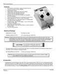
1
Operating Instructions
Please read and save these instructions. Read carefully before attempting to assemble, install, operate or maintain the product described.
Protect yourself and others by observing all safety information. Failure to comply with instructions could result in personal injury and/or
property damage! Retain instructions for future reference.
Generators
CAMPBELL
HAUSFELD
Description
These generators are powered by aircooled four cycle engines and designed
to run at maximum RPM and give a
continuous wattage as rated. On
certain models, a low-oil level shutoff
is provided to protect the engine. This
feature is usually associated with
extended run models.
Unpacking
When unpacking, inspect carefully for
any damage that may have occurred
during transit. Make sure any loose
fittings, bolts, etc., are tightened
before putting unit into service.
General Safety
1. Before starting or
servicing any
generator, read
MANUAL
and understand all
instructions. Failure
to follow safety
precautions or instructions can
cause equipment damage and or
serious personal injury. Engine
instructions for these units are
contained in a separate manual.
Retain all manuals for future
reference.
2. Never use this generator for any
application other than that
specified by the manufacturer.
Never operate this generator under
conditions not approved by the
manufacturer. Never attempt to
modify this generator to perform in
any manner not intended by the
manufacturer.
3. For maintenance and repairs, use
only products and parts
recommended by the
manufacturer.
4. Be sure that the generator is
properly grounded to an external
ground path prior to operation.
Refer to the section entitled
"Grounding Instructions" for proper
grounding procedures.
Do not operate this
generator on wet
surfaces or in the rain.
5. Be sure that the generator is
operated only by persons who have
read and understand these
instructions.
13. Never operate the generator with
damaged, broken or missing parts,
or with any guarding components
removed.
6. Be sure that the generator is placed
on a flat level surface prior to and
during operation. The generator
must not slide or shift during
operation.
Shut off the
generator engine
and disconnect the spark plug wire
before performing any service or
maintenance to the unit.
7. Keep all persons away from the
generator during operation.
8. Do not allow persons wearing loose
clothing or jewelry to start or
operate the generator. Loose
clothing or jewelry may become
entangled in moving components,
causing equipment damage and or
personal injury.
9. Keep all persons away from parts
that move or become hot during
operation.
10. Be sure all powered devices are shut
off prior to connecting them to the
generator.
11. Keep the generator clean and well
maintained at all times.
Never operate this
generator in an
explosive atmosphere
or poorly ventilated
area.
12. Be sure that all tools and appliances
are in good repair and are properly
grounded. Use devices that have
three prong power cords. If an
© 1996 Campbell Hausfeld
extension cord is used, be sure that
it has three prongs for proper
grounding.
14. Use only unleaded fuel. Do not refill
the fuel tank while the engine is
running. Use precautions to prevent
fuel spillage during refills. Be sure
the fuel tank cap is securely in place
before starting the engine. Clean up
any spilled fuel before starting the
engine. Allow engine to cool for at
least two minutes before refueling.
15. This generator may be used for
emergency stand-by service. In such
cases, a manual transfer switch must
be installed between the electric
utilities meter and the electrical
distribution box. This switch should
be installed by a licensed electrician.
Never mix oil with
gasoline for this
engine. This is a four cycle engine
designed to run on pure gasoline. Oil is
used for engine lubrication purposes only.
Operation
PRE-OPERATION
1. Check engine oil level. Oil is NOT
mixed with the gasoline, however
adequate oil supply is necessary for
proper engine lubrication. Refer to
the Engine Manual for SAE, API and
fill quantity specifications.
IN198203AV 11/96
1
Operating Instructions
2. Use of a Ground Fault Interrupter
(GFI) is strongly recommended.
Ground Fault Interrupters can
significantly reduce the possibility of
injury if an electrical short occurs. In
order to install a GFI, the generator
neutral wire must be internally
grounded to the generator frame,
and the frame must be properly
grounded to the earth.
A Ground Fault
Interrupter may
not be effective if used on a generator
that is not grounded! Refer to the
section entitled Grounding for proper
steps to ground the generator.
3. When installing a GFI, be sure to
follow all national and local
regulations. If not sure of
regulations or procedures, obtain
assistance from a qualified (licensed
or certified) electrical technician.
GROUNDING
1. Use the ground terminal and wing
nut on the generator frame to
connect the unit to a suitable
ground source. Securely fasten the
end terminal of the ground wire to
the ground terminal on the
generator frame. Tighten the
washer and wing nut on top of the
ground wire end terminal.
2. The ground wire should be made of
#8 gauge wire. Do not use wire with
a higher gauge number. Higher
gauge numbers indicate thinner
wire, which may not provide an
adequate ground path.
3. The other end of the ground wire
must be securely fastened to an
approved ground source.
The following are ground sources
approved by the National Electric Code.
Other ground sources may be
acceptable. Refer to the National Electric
Code and local regulations for further
ground source information. If not sure
of regulations or procedures, obtain
assistance from a qualified (licensed or
certified) electrical technician.
EXTENSION CORDS
MAXIMUM RECOMMENDED LENGTHS (IN FEET)
Amps
Watts
120 V
Watts
240 V
2.5
5
7.5
10
15
20
25
30
40
300
600
900
1200
1800
2400
3000
3600
4800
600
1200
1800
2400
3600
4800
6000
7200
9600
#8
Wire
175
150
125
90
a. An underground water pipe at
least ten feet in length
b. A non-corrosive underground
pipe at least eight feet in length
and 3/4 inch diameter
c. A steel or iron underground rod
at least eight feet in length and
5/8 inch diameter
d. A non-ferrous rod at least eight
feet in length, 1/2 inch in
diameter, and approved for
grounding purposes
Any rod or pipe used for grounding
must be driven to eight feet deep or
buried in the deepest possible trench.
STARTING
1. Remove all electrical loads from the
generator.
2. Rotate fuel shut-off valve counter
clockwise to enable fuel flow.
3. Rotate the engine switch to the ON
position.
4. Adjust the choke lever as follows:
a. For cold engine, move the choke
lever as far as possible to the left,
choke fully ON, position.
b. For warm/hot engine, move the
choke lever midway between the
choke and run positions.
5. Pull the starter rope with a brisk,
smooth motion.
#10
Wire
#12
Wire
#14
Wire
#16
Wire
1000
500
350
250
150
125
100
65
600
300
200
150
100
75
60
375
200
125
100
65
50
250
125
100
50
NOTE: Some models may be equipped
with an electric starter. For models
equipped with an electric starter, press
the start button.
6. After each start up, allow the
engine to run for 2-3 minutes with
no load.
7. As the engine warms up and
stabilizes, adjust the choke lever to
the right, until the lever is
positioned at the RUN label.
Engine speed is
preset to provide
proper output voltage. Never attempt
to modify or adjust engine speed or
output voltage.
ENGINE BREAK-IN
After initial start-up, the engine should
be broken in according to the
manufacturer's instructions. Refer to
the engine manual for the proper
break-in procedure.
GENERATOR SHUT OFF
1. Shut off and remove all electrical
load devices from the generator.
2. Allow the engine to run for 2-3
minutes with no electrical loads.
3. Rotate the engine switch to the OFF
position.
4. Verify that the generator has
completely stopped.
5. Close the fuel supply valve.
6. Allow the unit to cool before
installing any covers.
2
Operating Instructions
LOAD DEVICES
1. All load devices and extension cords
should use three prong terminals.
Refer to the following chart for
extension cord and cable size
requirements.
2. Allow the engine to run for 2-3
minutes before applying any
electrical loads.
3. The 120 volt receptacles are rated
for 15 amps and may be used in any
combination of 120 volt loads and
also with 240 volt loads through the
240 volt receptacles.
The 240 volt receptacles are rated
for 20 amps and may be used in any
combination of 240 volt loads and
also with 120 volt loads through the
120 volt receptacles.
The 120/240 volt twist lock
receptacle, found on some units, is
rated for 20 amps and may be used
in any combination of 120 volt and
240 volt loads.
4. Individual receptacles should not be
loaded beyond the amperage
rating.
5. Total combined load through any
combination of receptacle must not
exceed the rated load limits of the
generator. Refer to the
identification plate on the
generator for amp and wattage
specifications.
6. Always shut off and remove loads
before starting or shutting off the
generator engine.
7. When plugging multiple electrical
load devices into the generator
receptacles, be sure to connect and
activate the highest power draw
item first. Allow the generator
engine to stabilize, then connect
and activate the next highest power
draw device. The smallest power
draw device should be connected to
the receptacle and activated last.
NOTE: Power draw can be calculated
by multiplying volts and amps. The
resulting number is wattage.
Never exceed the posted maximum
wattage for the generator or any
individual receptacle. Refer to owner's
manuals and product tags to determine
the wattage of all electrical load devices.
ESTIMATED POWER USAGE (WATTS)
Load Device
Watts
Load Device
Air conditioner
2000-3000
Radio
Automatic washer
150-1500
Refrigerator
Brooder
100+
Skillet
Watts
50-200
190-2000
1200
5000-10,000
Space heater
600-4800
Coffee maker
400-700
Sump pump
400-3000
Electric drill (small)
225-1000
Television
200-500
Electric drill (large)
500-1000
Clothes dryer
Toaster
900-1700
40-200
Vacuum cleaner
200-300
Freezer
300-500
Water pump
1000-3000
Hot plate
330-1100
Water heater
1000-5000
Iron
500-1500
Small hand saw
1000-2000
Light bulb
As Rated
Large hand saw
1500-2500
Fan
If actual watt ratings are not available,
the following chart may be used as a
general guideline.
Remember that devices which generate
heat during operation such as heaters,
incandescent light bulbs, motors and
hair dryers have a higher power draw
than devices which generate little heat
during operation such as florescent
bulbs, radios, and clocks.
Long power cords and extension cords
also draw additional power. Keep cords
at minimum possible length.
Refer to the chart provided for
maximum limits for lengths of
extension cords.
8. Circuit protection is provided by a
circuit breaker. The circuit breaker
opens when the generator load
exceeds its maximum capacity or a
short circuit occurs. If the circuit
breaker opens, perform the following
procedures to correct the problem:
a. Shut off and disconnect all
electrical loads.
Repeated cycling
of the circuit
breaker indicates a problem and may
cause damage to the generator or load
devices. Do not operate the generator
if repeated cycling of the circuit
breaker occurs.
LOW OIL SHUTDOWN
A low oil shutdown switch is provided
to protect the engine and generator on
most extended run models. When
engine oil level drops too low for
proper engine operation, the low oil
shutdown switch causes the engine to
shut off. If oil level is low when
attempting to start the generator
engine, the low oil level shutdown
switch prevents the engine from
starting. If engine does not start, check
oil level.
NOTE: It is important to keep the
generator unit on a level surface. The
oil level shutdown switch can prevent
the engine from starting even if oil
level is sufficient, when the generator
unit is placed on an uneven surface.
Installation for Stand-by Use
c. Do not use any devices that have
short circuits. Avoid overloading
the generator.
Precautions must be taken to prevent
electrical back feeding into utility
systems. This requires isolation of the
electrical system. To isolate the
electrical system, perform the following
procedures:
d. Press the circuit breaker
pushbutton to reset the circuit
breaker.
1. Turn off the main electrical system
switch prior to connecting the
generator.
b. Attempt to determine the cause
of the electrical problem overloading or short circuit.
3
Operating Instructions
2. In accordance with national and
local standards, a double throw
transfer switch must be installed in
the system.
following prestorage procedures
should be performed:
Always shut off
main power prior
to temporary connection of the
generator to a building electrical
system.
2. Drain all fuel from the tank, lines,
carburetor and fuel valve.
Installation of the
generator as a
backup electrical source must be
performed by a qualified (licensed or
certified) electrical technician.
Maintenance
INFREQUENT USAGE
If the generator is used infrequently,
starting difficulty may occur. To help
prevent difficulty starting, the
generator should be run for
approximately 30 minutes per week.
STORAGE
If the generator is not to be used for
extended periods of time, the
1. Make sure engine oil is filled to the
proper level.
3. Remove the spark plug, and pour
approximately one teaspoon of oil
into the spark plug hole.
4. Pull the starter cord several times to
spread the oil throughout the
cylinder.
Whenever the generator is stored, be
sure that the fuel shut-off valve is in
the closed position.
Refer to the engine manual that
accompanies this unit for instructions
regarding maintenance of engine
components.
Never tamper with
engine speed
settings or generator frequency
settings. Any governor adjustments
should be made by qualified personnel
only.
5. Slowly pull the starter cord, until
resistance is felt. This indicates that
the piston is moving upward on the
compression cycle, and the intake
and exhaust valves are closed. (The
piston pushes a small amount of air
from the spark plug hole on
compression.)
6. Use of anti-gumming agents in the
fuel system can help prevent the
build up of gum and varnish.
Limited Warranty
1. DURATION: One year from the date of purchase by the original purchaser. Units used for rental or commercial purposes are warranted for 90 days from date of purchase.
2. WHO GIVES THIS WARRANTY (WARRANTOR):
The Campbell Group / A Scott Fetzer Company
100 Production Drive
Harrison, Ohio, 45030
Telephone: (513) 367-4811.
3. WHO RECEIVES THIS WARRANTY (PURCHASER): The original purchaser (other than for purposes of resale) of the Campbell Hausfeld product.
4. WHAT PRODUCTS ARE COVERED BY THIS WARRANTY: Any Campbell Hausfeld portable generator supplied or manufactured by Warrantor.
5. WHAT IS COVERED UNDER THIS WARRANTY: Defects on material and workmanship which occur within the duration of the warranty period.
6. WHAT IS NOT COVERED UNDER THIS WARRANTY:
A. Implied warranties, including those of merchantability and FITNESS FOR A PARTICULAR PURPOSE ARE LIMITED TO ONE YEAR FROM THE DATE OF ORIGINAL PURCHASE. Some
states do not allow limitations on how long an implied warranty lasts, so the above limitations may not apply to you.
B. ANY INCIDENTAL, INDIRECT, OR CONSEQUENTIAL LOSS, DAMAGE, OR EXPENSE THAT MAY RESULT FROM ANY DEFECT, FAILURE, OR MALFUNCTION OF THE CAMPBELL
HAUSFELD PRODUCT. Some states do not allow the exclusion or limitation of incidental or consequential damages, so the above limitation or exclusion may not apply to you.
C. Any failure that results from an accident, purchaser’s abuse, neglect or failure to operate products in accordance with instructions provided in the owner’s manual(s) supplied
with product.
D. Pre-delivery service, i.e. assembly, oil or lubricants, and adjustment.
E. Normal adjustments which are explained in the owner’s manual(s) provided with the product, i.e. belts, pressure switch.
F. Items or service that are normally required to maintain the product, i.e. lubricants, filters and gaskets.
G. Electric motor and gasoline engine components are expressly excluded from coverage under this limited warranty. Such components should be returned by the purchaser to
the original manufacturer or to its authorized repair stations for service.
7. RESPONSIBILITIES OF WARRANTOR UNDER THIS WARRANTY: Repair or replace, at Warrantor’s option, products or components which have failed within duration of the
warranty period.
8. RESPONSIBILITIES OF PURCHASER UNDER THIS WARRANTY:
A. Deliver or ship the Campbell Hausfeld product or component to the nearest Campbell Hausfeld Authorized Service Center. Freight costs, if any, must be borne by the
purchaser.
B. Use reasonable care in the operation and maintenance of the products as described in the owner’s manual(s).
9. WHEN WARRANTOR WILL PERFORM REPAIR OR REPLACEMENT UNDER THIS WARRANTY:
A. Repair or replacement will be scheduled and serviced according to the normal work flow at the servicing location, and depending on the availability of replacement parts.
B. If the purchaser does not receive satisfactory results from the Authorized Service Center, the purchaser should contact the Campbell Hausfeld Product Service Department (see
paragraph 2).
This Limited Warranty gives you specific legal rights and you may also have other rights which vary from state to state.
4
Operating Instructions
Troubleshooting Chart
Symptom
Alternator field is not energized
Low output voltage with no load
High output voltage with no load
Low output voltage under load
Erratic output voltage
Noisy operation
Possible Cause(s)
Corrective Action
1. Engine speed is too slow
1. Adjust engine speed ✽
2. Open, shorted, or incorrect wiring
2. Referring to the wiring diagram,
clean and reconnect all wiring ✽
3. Faulty capacitor
3. Replace capacitor ✽
4. Open or shorted field windings
4. Test winding resistance, replace
field winding if necessary ✽
5. Open diodes
5. Test diodes, replace if necessary ✽
1. Engine speed is too slow
1. Adjust engine speed ✽
2. Open diodes
2. Test diodes, replace if necessary ✽
3. Faulty capacitor
3. Replace capacitor ✽
4. Open or shorted field windings
4. Test winding resistance, replace
field winding if necessary ✽
1. Faulty capacitor
1. Replace capacitor ✽
2. Engine speed is too fast
2. Adjust engine speed ✽
1. Open diode
1. Test diodes, replace if necessary ✽
2. Engine speed too slow at full load
2. Adjust engine speed ✽
3. Excessive load applied
3. Reduce the applied load
1. Unbalanced engine
1. Refer to engine manual
2. Dirty, corroded, or loose wiring
connection
2. Referring to the wiring diagram,
clean and reconnect all wiring ✽
3. Unstable load applied
3. Remove all loads, then apply each
one individually to determine which
one is causing erratic function
1. Loose generator or engine bolt
1. Tighten all mountings
2. Short circuit in generator field or
load
2. Test winding resistance, replace
field winding if necessary ✽
Test load devices for shorts. Replace
defective load device.
3. Faulty bearing
3. Replace bearing
✽ These diagnostic and repair procedures should be performed by an authorized service center.
5
Operating Instructions
Rotor
Yellow
Stator
120 V Duplex
Receptacle
NEMA 5-15R
Tab broken
on brass side
White
Main
Winding
120V
Blk
Red
Red
Red
Circuit
Breaker
Green
Gn
Red
Blk
Control
Panel
Models
Only
Gn
Main
Winding
120V
240 V Duplex
Receptacle
NEMA 6-20R
Gn
Gn
Blk
Blk
Circuit
Breaker
Capacitor
Excitation
Winding
Idle Control
Circuit Board
Idle Control
OFF - ON
Idle
Control
Magnet
Idle Control
Models Only
Figure 1 - Generator Wiring Diagram For Dual Voltage Models
White
Rotor
Stator
Circuit
Breaker
Main Winding
120 V
Black
120V
Duplex Receptacle
Nema 5-15R
Black
Main Winding
120 V
White
Field
Winding
Capacitor
Figure 2 - Generator Wiring Diagram For Single Voltage Models
6
Operating Instructions
TESTING GENERATOR DIODES
The following method eliminates the need to disconnect the
diodes from the generator wiring.
1. Use a 12 Volt battery and automotive lamp (Type 5001) to
test the diodes in the generator.
2. Connect the battery and lamp as shown in Figure 3.
3. If the diodes are operating properly, the lamp illuminates
brightly when the battery polarity is correct, and goes
dim when battery polarity is reversed.
4. If there is no change in lamp brightness when polarity is
reversed, the doides must be replaced.
Lamp Dim
For testing of rotor, stator, or field
windings, consult an authorized service
Lamp Bright
Figure 3 - Diode Test Procedure
center.
7
Operating Instructions
Notes
8