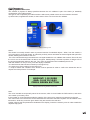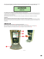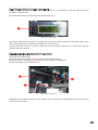
1
SPAZIO
User’s manual
77061373
01
INDEX
5
5
6
6
7
7
8
8
8
9
10
11
11
12
15
15
16
17
17
18
19
20
21
22
22
22
23
23
24
1
1.0
1.1
1.1.1
1.2
1.3
1.3.1
1.4
1.5
1.5.1
1.5.2
1.6
1.6.1
1.6.2
1.6.3
1.6.4
1.6.5
1.6.6
1.7
1.7.1
1.8
INFO
INTRODUCTION
THIS HANDBOOK
TECHNICAL TERMS
PROPOSED USE
PRODUCT IDENTIFICATION
POSSIBLE CONFIGURATIONS
PERSONS INVOLVED
SAFETY GUARANTEE
PROTECTION FROM THEFT AND VANDALISM
PROTECTING DATA BY AUTHENTICATION
THE P&D MACHINE COMPONENTS
CASING
TECHNICAL VAULT AND ELECTRICAL SUBSYSTEM
(A)
LCD
(B)
CPU, POWER SUPPLY AND BACKPLANE P.C. BOARDS
(C)
CONSOLE INTERFACE BOARD
(D)
CHIP CARD READER/WRITER
(E)
COIN VALIDATOR UNIT
(F)
PRINTER UNIT
(G)
FUSE
(H)
OPTIONAL GSM/GPRS MODEM
CASH VAULT
ELECTRICAL CONNECTIONS AND BATTERIES VAULT
SOLAR PANEL
INCLUDED FITTINGS
THE “SMARTPARK” SOFTWARE
HARDWARE AND SOFTWARE REQUIREMENTS
TECHNICAL FEATURES
25
25
25
25
26
26
26
29
29
2
2.0
2.0.1
2.0.2
2.0.3
2.1
2.1.1
2.2
2.2.1
P&D MACHINE PARTS
INSTALLATION
SAFETY MEASURES DURING FREIGHTING
SAFETY MEASURES FOR INSTALLATION
PREPARING THE INSTALLATION AREA
TRANSPORT AND FIXING ON SITE
POSITIONING OF FOUNDATION CLAMP
P&D MACHINE ACTIVATION
GPRS CONNECTION CHECK
30
30
30
30
30
3
3.0
3.1
3.1.1
3.1.2
CONFIGURATION AND PROGRAMMING
INTRODUCTION
HARDWARE CONFIGURATION
DIP SWITCHES CONFIGURATION
CONFIGURATION OF PIN CODE (OPTIONAL)
02
31
32
32
32
32
32
32
33
33
33
33
34
34
34
34
35
36
36
37
37
38
39
39
39
39
39
40
41
44
45
45
45
45
3.1.3
3.2
3.2.1
3.2.2
ADJUSTING THE DISPLAYS CONTRAST
SOFTWARE CONFIGURATION
INTRODUCTION
CONNECTING TO A PC
(A)
STANDARD P&D MACHINE
(B)
P&D MACHINE CONNECTED TO SERVER
3.2.3 INITIALIZATION
3.2.4 THE SMARTPARK MENU
3.2.5 PARAMETERS CONFIGURATION
(A)
GENERAL DATA
(B)
CONNECTIVITY
(C)
TIME
(D)
PAYMENTS
(E)
MONEY
(F)
TARIFFS
(G)
WARNING SIGNALS AND ALARMS
(H)
POWER SUPPLIES
(I)
MISCELLANEOUS
3.2.6 CHOOSING A LANGUAGE
3.2.7 CONFIGURATION OF DISPLAY MESSAGES
3.2.8 MANAGING USER TYPES
3.2.9 DATE AND TIME
3.2.10 DEFINING TARIFF RULES
(A)
INTRODUCTION
(B)
SETTING
(C)
CONFIGURATION
(D)
BASIC TARIFFS
(E)
DAILY TARIFFS
(F)
PLANNING THE P&D MACHINE SERVICE
(G)
SPECIAL USERS
3.2.11 UPDATING SMARTPARK SOFTWARE
(A)
UPLOADING FUNCTIONS
(B)
DOWNLOADING FUNCTIONS
46
46
46
46
46
47
47
47
48
48
48
49
49
4
4.0
4.1
4.1.1
4.1.2
4.2
4.2.1
4.2.2
4.3
4.4
4.4.1
P&D MACHINE PAYMENT OPERATION
INTRODUCTION
CONDITIONS
P&D MACHINE NOT AVAILABLE
P&D MACHINE IN SERVICE
UNDERSTANDING AND USING INPUT AND OUTPUT DEVICES
DISPLAY
INTERNAL ACOUSTIC SIGNALLER (BUZZER)
OPERATION LOGIC
OPERATION DETAILS
CONFIGURATION OF TRANSACTION
(A)
THE AMOUNT INSERTED IS LESS THAN TO THE MINIMUM AMOUNT REQUIRED
(B)
THE AMOUNT INSERTED IS GREATER THAN OR EQUAL TO THE MINIMUM
AMOUNT REQUIRED
03
50
51
51
52
53
53
53
54
54
4.4.2
4.4.3
56
56
57
58
60
60
60
60
60
61
61
63
63
65
65
65
66
66
66
67
67
67
68
69
69
69
70
70
71
71
72
73
74
5
5.0
5.1.1
5.1.2
5.2
5.2.1
5.2.2
5.3
5.3.1
5.3.2
5.3.3
5.3.4
5.5.5
5.6
MAINTENANCE
INTRODUCTION
TECHNICAL VAULT
CASH VAULT
SWITCHING THE P&D MACHINE ON AND OFF
SWITCHING ON
SWITCHING OFF
ORDINARY MAINTENANCE
PAPER ROLL SUBSTITUTION
CASH-BOX LOG REQUEST
TAKINGS WITHDRAWAL
TAKINGS COUNT AND REPORT PRINTOUT
(A)
INFORMATION PRINTED ON THE CASH-BOX EXTRACTION
P&D MACHINE OPERATIONAL CHECK
LOGS
(A)
TRANSACTIONS LOG
(B)
REVENUES LOG
(C)
EVENTS LOG
CASH-BOX LOG
SUPPLEMENTARY MAINTENANCE
SAFETY PRECAUTIONS
(A)
PERSONAL PROTECTIVE EQUIPMENT
EVENTS - THE P&D MACHINE’S MODE OF OPERATION
MAKING THE P&D MACHINE OPERATIONAL
TECHNICAL VAULT COMPONENTS REPLACEMENT
(A)
DISPLAY AND DISPLAY CARD
(B)
CPU BOARD
(C)
SERIAL COMMUNICATIONS BOARD
(D)
CARD READER
(E)
COIN VALIDATOR UNIT
(F)
PRINTING UNIT
FUSES CHECK
LONG PERIOD STOP
75
76
6
6.0
APPENDIX
EVENTS LOG CODES LISTING
4.4.4
4.4.5
4.4.6
5.4
5.4.1
5.4.2
5.5
5.5.1
5.5.2
5.5.3
5.5.4
END OF THE TRANSACTION AND TICKET PRINTOUT
PREPAYMENT
(A)
PREPAYMENT WITH COINS
(B)
PREPAYMENT WITH CARD
CANCELLING THE TRANSACTION
(A)
CARD PREPAYMENT
(B)
COIN PREPAYMENT
CHOOSING THE LANGUAGE
CHOOSING THE TARIFF
04
INFO
This chapter provides a brief guide to the pay and display machine features.
Further information can be found in the APPENDIX.
1.0 INTRODUCTION
Congratulations for having chosen a Solari di Udine S.p.A. product!
You have purchased a safe and highly reliable professional machine.
The “Spazio” pay and display machine has been designed according to the most recent electronic technologies
and thanks to the long experience matured in pay and display machines, we guarantee very high levels of
efficiency and safety and so are confident you will be a satisfied customer.
Ever since the ealy hours of design, our principle aim has been to provide you with an easy-to-use intuitive
user interface backed up by a sturdy and reliable machine.
Solari di Udine S.p.A. reserves the right to modify specifications and technical/functional characteristics of the
product at any moment without notice.
Technical questions and copies of this handbook can be addressed to:
SOLARI DI UDINE S.P.A.
via Gino Pieri 29
33100 UDINE
Tel. (0432) 4971 (switchboard)
Fax (0432) 480160
Email [email protected]
Web site www.solari.it
IMPORTANT:
• On receiving the “Spazio” P&D machine, please check that it is devoid of damage deriving from inadequate
transport and that all the accessories provided are present and devoid of damage.
• The “Spazio” P&D machine is wrapped up in a plastic covering and fitted to a wooden pallet. The casing
also contains P&D machine installation material including a small bag of nuts, bolts and necessary tools for
open/close operations on the various functional-zones within the “Spazio” P&D machine.
• To ensure good storage, be sure to keep the P&D machine within its original packaging and store it in a dry,
clean and sheltered area.
05
1.1 THIS HANDBOOK
Doc. Code: 77061071
Version: 1.1
Contents: User Handbook
Release: May 2006
Previous Release: July 2005
Intended users: Installer, maintenance and takings personnel
The scope of this handbook is to inform and guide the installer, user and “Spazio” P&D machine maintenance
technician to correctly perform the various maintenance routines.
It has been subdivided into six chapters for the sake of clarity:
• INFO: Presentation and description of the P&D machine
• INSTALLATION: Describes the installation procedure for the P&D machine
• PROGRAMMING: Programming and settings information for the P&D machine
• USE: User instructions for the P&D machine
• MAINTENANCE: Maintenance information for the P&D machine
• APPENDIX: Summary tables of the most important information. Some additional matters are also reported.
Highlighted text with a dark-coloured background serves for section identification and is placed in the lower part of each
page.
Notes:
• This handbook describes all parts, including the optionals, which may not be featured in this package. Please note that parts
not included are machine-type specific and not necessarily missing. Refer to your product checklist.
• All illustrations used in the general descriptive paragraphs refer to the basic model of the P&D machine.
• This document includes information related to as yet unavailable Solari di Udine S.p.A or third party products and services.
These references do not entail actual future release of the afore mentioned.
• This handbook does not replace the P&D machine training couse held by Solari di Udine S.p.A.’s technical personnel.
• From chapter 4 onwards you will find customer information for the correct utilization of the P&D machine, such as payment,
ticket withdrawal and information requesting.
As for obvious reasons, this handbook cannot be made available to the customer, we suggest that a short instruction list be
placed on body of the P&D machine to further simplify its use and to indicate hourly tariffs and minimum fee.
1.1.1 Technical terms
In reading this handbook some terms might be misunderstood. A short dictionary of terms used is available at
the end of the handbook in the Appendix section entitled DEFINITIONS.
Note for computer file visualization: all instructions described in the dictionary have a hypertextual link. Each
link has an italic style font and the mouse-pointer becomes a pointing hand when passing over it. A mouse click
on any such term will access the term definition.
06
1.2 PROPOSED USE
The P&D machine “Spazio” is highly suitable for urban parking area management and is manufactured
according to UNI CEI EN 12414 “Control Equipment for the Parking of Vehicles.Technical and functional
requirements for Parking meters” standards.
The P&D machine “Spazio” (briefly, P&D machine) can be easily integrated to constitute part of a pay-andservices management system (eg. public transport, car wash, ecc.). It has a basic model, which includes a
coin-and-card reader, and other models which differ according to the way transactions are made (i.e. optional
components installed).
Communication between the P&D machine and the operator can be obtained via the Ethernet, serial link, or,
optionally, Gsm/Gprs. The user-panel enables the customer to interact with the P&D machine.
The P&D machine incorporates a user-friendly Web interface which allows for simple machine-user interaction,
whereby all essential information can be programmed (P&D machine parameter set-up for varying the methods
of payment and the consequent transactions generated).
Configuration parameters can be customized according to actual implementations of the P&D machine and
saved to its internal database. Default factory settings have standard values which can be changed at any
moment in the P&D lifetime.
1.3 PRODUCT IDENTIFICATION
The P&D machine may be identified by a nameplate located inside.
P&D machine “Spazio” identification nameplate.
The “crossed-out basket-on-wheels” icon is only valid in the EU and indicates that when the P&D machine is
to be disposed of, it must not be considered normal urban waste, but it must be collected seperately.
To ensure proper handling, recovery and recycling the P&D machine is to be sent to the designated collection
points, where it will be collected without free of charge. Alternatively the P&D machine can be handed back to
the local retailer when purchasing a new P&D machine.
A correct disposal of the P&D machine will be a contribute towards saving precious resources and avoiding
possible negative effects on the environmentand on health. If the P&D machine is incorrectly disposed of,
sanctions based on national laws may be applied. Hence, it is recommended to follow the above-mentioned
disposal instructions. For further details and information please contact your local authority (eg. municipality)
or your nearest waste collection point.
To identify the correct hardware configuration of the P&D machine provided, refer to the documents regulating
the commercial contract.
Note: the P&D machine has a modular structure. Some parts are always present, others are optional. The next
paragraph explains this modularity.
07
1.3.1 Possible configurations
The basic P&D machine model is powered by a Solar-panel-charged 12V 18Ah rechargeable battery.
Other options available are:
• 12V - 56Ah high-capacity battery
• Additional non-rechargeable batteries together with a 12V 18Ah rechargeable battery
• external power supply together with a 12V 7.2Ah battery
• hybrid magnetic-and-chip-card reader
• GSM/ GPRS modem
1.4 PERSONS INVOVLED
USER:
or end-user is the person (customer) who makes use of the P&D machine
by purchasing a ticket for parking.
No P&D machine functioning knowledge needed.
MAINTENANCE:
trained personnel who has a working knowledge of P&D machine parts
and is capable of safely substituting parts and/or executing technical
manouvres to remove faulty parts.
MANUFACTURER:
Solari di Udine S.p.A.
TAKINGS COLLECTOR:
untrained personnel who’s aim is to collect the P&D machine’s takings
according to management instructions.
1.5 SAFETY GUARANTEE
The P&D machine “Spazio” is esentially safe and reliable: the high quality materials with which it has been
built, make it suitable to withstand the toughest working conditions:
Water-and-dust resistant
Operating temperature
Relative humidity (without condensate)
IP33 and IP54 (except for coin and card insertion slots)
from -10 to +55 °C
0-97%
In all versions the P&D machine is powered by a maximum 12 Vac supply voltage, thus meeting the required
safety standards. It is therefore considered “low-voltage equipment”.
PLEASE NOTE: If the P&D machine “Spazio” is used in operating conditions which differ from those
stated in this instruction handbook, or if components are tampered with, modified or replaced, the
producer declines any responsability for damages deriving from defective products (as per EU 85/374).
Consequently, the guarantee is no longer valid.
08
1.5.1 Protection from theft and vandalism
The P&D machine is equipped with a solid metal casing. The upper door (user panel), accesses the technical
vault, and the lower door accesses the cash vault; both are made of a high-resistance stainless steel sheet
metal.
User Panel
Upper access door
Lower access door
The user panel has been designed to resist any kind of vandalistic action. The buttons are of metal and
protrude slightly; the display and user panel are protected by a transparent vandal-proof varnish.
Vandal-proof button
In addition to the lower access door, access to the cash vault is prevented by an internal door fitted with a
safety key lock.
Internal Access
door
Case
Accessing the cash vault
09
The cash vault, besides being fitted with a key lock door, is also provided with a catch-type safety-door latch
which impedes access to the actual cash when the cash-box is taken out.
Safety Access door
Cash-box
To prevent unauthorized access to the various vaults, each lock has is a unique key to open it. This specific keyand-lock combination guarantees a high security level, and consequently different persons (i.e. maintenance
or takings personnel) have responsibility over different areas of the P&D machine “Spazio”.
1.5.2 Protecting Data by authentication
A web-based interface limits remote access to the P&D machine’s confidential data through a username/
password scheme to authorized personnel only. Authentication usernames and passwords are inserted in the
P&D machine’s permanent memory during system initialization.
Thus, access to the P&D machine is gained through username/password authentication. Permission to
interact with the P&D machine functions is only granted to those operators with a valid username/password
combination; any unauthorized attempt to access the P&D machine fails. Username/password data and P&D
machine IP address have default factory settings until they are changed on P&D machine start-up.
An authenticated operator can change user-data such as privileges, passwords and he can also add new
users with different privileges. (A privilege is the permission to execute specific operations).
With the SmartPack software, operators have access to a possibly reduced set of system functions.
The SmartPack software checks the logged-in user’s privileges for permission to execute before processing the
requested system function. If permission is denied an error message occurs and the function is not executed.
10
1.6 THE P&D MACHINE COMPONENTS
The P&D machine “Spazio” is made up of the following fundamental elements:
1) Casing
2) Technical vault
3) User panel
4) Cash vault
5) Electrical/mains connection and batteries vault
• Solar panel
• Accessories included
The P&D machine “Spazio” has been designed with indipendently accessible vaults; the Management and
Maintenance staff have acces only to their particular area of responsibility.
1.6.1 Casing
The P&D machine “Spazio” vaults are contained in and protected by the robust casing. The 1.55mm-thick AISI
304 STAINLESS STEEL casing has excellent characteristics of sturdiness, inalterability and recyclability.
The upper access door comprises the user panel on the outside and gives access to the
technical vault within. The lower door gives access to the cash and the electrical connections vaults.
6
1
2
3
4
5
P&D machine components
11
1.6.2 Technical vault and electrical subsystem
The electrical subsystem is located in the upper sectin of the P&D machine and is accessible when the user
panel is open. To open the user panel insert the appropriate key in the vault-opening key-lock placed above
the user panel.
Vault opening
lock
Open vault
Opening the vault
A vault behind the display contains the Cpu card and its power supply. To gain access to the vault press the
metal tabs placed on either side of the display holder and rotate the panel outwards and downwards.
Display vault opening
Open display vault
12
On the rear face of the user panel the following device mountings are to be found:
1) LCD Display;
2) CPU, power supply and backplane p.c. boards
3) Card reader-and-writer unit
4) Printer unit
5) Coin validator unit
6) GSM/GPRS Modem
• Optional serial communications p.c. board
• Fuses
1
2
Technical vault
4
3
Technical vault
13
5
Technical vault
6
Technical vault
14
(A) LCD Display
The P&D machine is equipped with a 20 character by four lines matrix LED backlight liquid crystal display.
Message display example
The messages appearing on the display inform and guide the customer toward succesful pay operations.
These messages can be made to appear in either of four languages (for further information see the chapter on
page 35 entitled “CONFIGURATION AND PROGRAMMING).
The display board mountings comprise the LCD display , interface circuitry and backlight power supply.
Display Card
(B) CPU , power supply and backplane p.c. boards
The management software resides on the CPU board, to which all the other P&D machine’s functional units
are connected (i.e. pc.boards and peripherals).
KEY:
1) Cpu
2) Backplane
3) power supply board
4) Ethernet connector
5) Panel-closed sensor switch
A buzzer mounted on the CPU board emits a tone to signal that an operation is in progress. Its volume is
controlled via the CPU.
4
1
3
5
2
15
The backplane comprises the following parts:
1
2
3
4
5
6
9
7
8
1
10
11
12
KEY:
1) Cpu Board Connector
2) C/RV – Power supplies connector, user panel and cash vault access door contacts
3) C/RV1 – NOT USED
4) INFR – Console Serial connector
5) CDY – Display Connector
6) LTC – Chip card reader connector
7) STP – Printer Connector
8) GT/A – Slot Connector
9) TST – Keys Connector
10) VXALIM - Modem Jumper selector
11) CD – Gprs Modem Serial lines Connector
12) LB – NOT USED
(C) Console interface board
This board hosts serial-interface electronics and connects the P&D machine to a maintenance console and is
used by maintenance personnel.
16
(D) Chip Card Reader/Writer
The P&D machine is provided with a Chip Card Reader/Writer with choice between one of the following card
formats:
• Prepaid chip cards; whereby new fees are scaled down and total amount is continuously updated. The
customer selects the correct fee to be paid by pressing a specific button. This type of chip card is compliant
with the ISO 7816-3 standard.
• Magnetic-strip cards; for bank card management
The reading check and other parameters relative to the type of device installed are set by the programming.
All parameters relevant to the various Card Reader/Writer devices installed, as well as reading checks can be
set through proper device programming.
(E) Coin validator group and coin chute
The microprocessor controlled coin validator unit (coin validator) can be programmed to distinguish between
various coin types (for further information see “CONFIGURATION AND PROGRAMMING” ).
The coin validator components are:
15
6
7
8
9
10
11
12
13
14
3
5
5
2
1
Coin validator unit
KEY:
1) Shutter-open electromagnetic switch and proximity swich unit
2) coin validator unit
3) validator unit clasp;
4) escrow
5) temporary cash-holder fastener rods
6) quick release connector (OP2)
7) parallel communications connector
8) shutter connector
4
9) validation connector
10) rejection connector
11) sensor 1 connector (OO2)
12) parallel line ITB to CPU connectot
13) sensor 2 connector (OP2)
14) Serial line ITB to CPU connector
15) Shutter sensor connector
17
(F) Printer Unit
This P&D machine is provided with a long-life thermal printer with incorporated paper cutter with partial or
complete cutting facility.
Printing can be simple text or graphic.
A 6x11cm printed ticket can be seen dropping into the withdrawal vault thanks to the transparent weatherproof
window on the vault door. The ticket is emitted once at the end of a transaction and, each time the cash-box
is extracted (a report log is printed).
Ticket withdraw vault
The printer hosts a thermic paper roll with the following characteristics:
• Maximum width:
112 mm
• Maximum roll diameter:
105 mm
• Acceptable paper weight range:
60 – 75 g/mq
One roll can print up to 3000 tickets.
When choosing the type of paper you prefer, please note that tickets might be exposed to direct sunlight for a
long time and that printings must not become unreadable.
18
KEY:
1) Paper input
2) Printer removal clasps
3) Serial Data connector (RX-TX-GND)
4) Power supply connector
1
2
2
Gruppo stampante
3
4
(G) Fuse
An easily accessible fuse placed on the display panel protects the P&D machine’s electric circuits .
Note:
Only replace a blown fuse with a new one having the same current/time ratings as the original one; i.e. 3,15A delayed.
Fuse
19
(H) Optional GSM/GPRS Modem
With the aid of a GSM/GPRS modem an operator can monitor a P&D machine network and collect both P&D
machine data and functional statistics.
GSM standard communications occur via the fitted GSM antenna which permits an aerial link with the
“outside world”. For the P&D machine to communicate on the GSM aerial network, you need a contract with
a telecommunications operator and a chip-card (or SIM Card) with data communications via GPRS and SMS
messaging capabilities. Voice communication capabilities are not necessary. Fit the SIM card in the caddy,
then place the caddy in the SIM card holder in the GSM/GPRS modem.
Power the GSM/GPRS modem by placing a jumper on pins 2 and 3 of VXALIM selector. VXALIM is found on
the backplane board.
KEY:
1)
2)
3)
4)
5)
6)
7)
Power supply connector
GSM Antenna connector
Cpu communications connector
SIM card holder caddy
Modem active signalling LED
Audio interface connector – Not used
GSM Antenna
6
5
4
1
3
7
20
1.6.3 Cash vault
The cash vault covers the central area of the P&D machine and can be accessed opening the front door with
the aid of the maintenance key. An inner second door equipped with a heavy-duty lock restricts access to the
cash-box area within.
2
4
3
1
Accessing the cash vault
5
3
Accessing the cash vault
KEY:
1)
2)
3)
4)
5)
Vault access door
Brakeover door lock
Heavy-duty inner cash vault door
Inner door lock restricts access to cash-box
Cash box
21
1.6.4 Electrical connections and batteries vault
The P&D machiner “Spazio” requires a 12 Vcc supply voltage to operate.
The P&D machine’s supply voltage can be obtained in the following ways:
a) solar panel and a 12V 18Ah battery
b) external power supply and a 12V 18Ah battery
A complex “Energy Management” function built-in to the P&D machine controls accumulator charging during
normal functioning and switches off inactive peripherals for effective power-savings. This function therefore
ensures best performance and regular functioning for a long time.
Battery
Vano allacciamento elettrico e batterie
1.6.5 Solar panel
The basic P&D machine model is provided with a solar panel.
Solar panel
1.6.6 Included fittings
As previously mentioned the P&D machine is also provided with the following fittings:
(A) Keys
In order to differentiate access to the various “functional areas”, the P&D machine is provided with a set of four
keys, each having a different grip colour.
RED Key
Opens the user panel to access the technical vault and door to the cash-box.
Maintenance personnel
BLACK Key
Opens the lower front panel for access to the cash vault door.
Maintenance personnel
METAL Key
Opens the cash vault (which contains the cash-box)
Revenue collector
YELLOW Key
Opens of the cash-box
Revenue collector
Revenue collector
22
1.7 THE “SMARTPARK” SOFTWARE
This application program resides in the P&D machine’s memory and allows for P&D machine configuration,
to create and control parking policies, set up tariffs, dates, and P&D machine start-working and stop-working
times. This application has a web-based interface and can therefore be used via the Internet,.
This application program can:
• Manage configuration parameters, parking circuits and areas.
• Manage various types of tariff policies: linear, non linear, progressive, regressive and flat rate.
• Manage time rules.
• Manage the annual calendar, festivities, and special occasions.
• Manage the users and their assigned privileges.
• Carry out peripheral diagnostics.
• Consult events register, transaction logs and reports.
• Download P&D machine data and management software.
• Upload P&D machine registers data in text or excel format.
• Real-time P&D machine operating status checking
(in service, out of order, presence signalling, alarm signalling).
• Consult online help.
1.7.1 Hardware and Software Requirements
For successful P&D machine remote accessing, it is necessary to connect the P&D machine to a common
Personal Computer, provided with one of the following browsers: “Microsoft Internet Explorer”, “Netscape” or
“Mozilla Firefox”.
For practical purposes, the use of portable equipment such as a PC notebook with a network board, is
suggested.
To connect the PC directly to the P&D machine it is necessary to use an Ethernet 10BASET twisted cable.
Note: for an effective and coherent use of this program it is necessary to have a complete mastery of
the P&D machine’s functioning logic, which is described in detail in the chapter “CONFIGURATION AND
PROGRAMMING”.
23
1.8 TECHNICAL FEATURES
The main features of the P&D machine are reported in the following table.
FEATURE
VALUE
Overall dimensions (h x w x d):
Weight:
Power supply:
1852 x 490 x 269 cm
about 100 kg, depending on the models and the optional peripherals installed
• solar panel and 12V 18Ah battery
• external power supply and 12V 7,2 Ah battery
• battery cells and 12V 18Ah battery
• 12V 56Ah high capacity battery
Maximum current consumption:
Ethernet Connection:
7A at 12V
Twisted 10 Base-T cable, (as per IEEE 802.3 standard).
The protocol implemented is TCP/IP.
Serial Connection:
Degree of protection:
Operating temperature range:
Relative humidity (without condensate):
Processing unit :
Ram:
Non volatile memory:
Type of display:
Magnetic card reading format:
Chip-card Reading format:
Printer paper format:
Acoustic signaller:
Calendar clock:
Cash-box capacity:
Autonomy:
Asynchronous EIA RS232 serial line
IP33 e IP54 (except for coin and card slots)
-25°C - +55°C for models with external power supply
Max 97% at 50°C
32 bit RISC CPU running at 133 MHz
32 Mb RAM
16 Mb FLASH
Liquid crystal 4x20 matrix type
ISO 7810
ISO 7816
60 – 75 g/sq.m paper
Piezo BUZZER
Continuous, automatically synchronized with system time
5dm3
Minimum period: 6 months or 15000 transactions
24
P&D MACHINE PARTS
2.O INSTALLATION
2.0.1 Safety measures during freightage
In order to safely transport and set up the P&D machine, the personnel involved in the freightage operations
and activation, needs to be appropriately instructed and trained.
The following fundamental regulations must be respected:
• Every operator must wear the appropriate accident-prevention clothing, as prescribed by law (safety
shoes in particular);
• The lifting equipment used must bear the EU label, i.e. the carrying-capacity must be guaranteed and
clearly visible on the lifting equipment;
• During transportation of the P&D machine, the latter must be carried in its original packaging and
handled by means of appropriate lifting equipment.
• Check the good working conditions of the lifting equipment (ropes, chains, hoists, cranes, trolleys,
etc.), and lifting-capacity congruent to the P&D machine weight. Check the coupler devices and
corresponding lifting elements for good accesssiblility, stability and self-locking connections.
• While lifting and carrying the P&D machine , ascertain that no one passes near or under the moving
load. Avoid impacts, jerks, oscillations and vibrations when the P&D machine is being moved. Set the
P&D machine down with the utmost care.
• Once it has reached its destination, the P&D machine can be carried with a suitable trolley or
transpallet, by inserting the lifting forks into the P&D machine base.
• The P&D machine handling area must be free from obstacles that might constitute a danger to people
or things.
2.0.2 Safety measures for installation
Regarding safety, and specifically protection against electric shock, the P&D machine is part of Class III
equipment, as defined by European Standard CEI EN 60950 (corresponding to the CEI 74-2) as follows:
“Equipment in which electric shock protection is based on a very low voltage power supply coming from safety
circuits: whereby no dangerous voltage is generated.”
On the basis of this definition, the safety of P&D machine users, operators and maintenance personnel is
safeguarded because it operates at a very low voltage.
Consequently, it is essential that during installation and activation of the P&D machine , the installer personnel
operate in accordance with CEI Standard 64-8 (third edition, 1st March 1993. Part 4 of the afore-mentioned
Standard includes the safety precautions for the SELV (Safety Extra Low Voltage) equipments which must be
followed very carefully).
The installer is therefore liable for damages to people or things, due to the non-observance of the
measures contained in the above-mentioned Standard.
The fundamental measures are as follows:
• All electrical operations must be performed by a qualified electrician;
• make sure that all the necessary tools and materials to perform the installation are available; verify
that they are in good working condition and that they conform to the relative safety regulations;
• the use of any electrical sources, not explicitly recommended for this system (refer to the technical
specifications) may cause overheating, alteration of the system itself, fire, electric shock or other
dangers;
• use accessories supplied or recommended exclusively by Solari di Udine S.p.A.;
25
2.0.3 Preparing the installation area
(1) Locate the exact position where the P&D machine will be installed, preferably in the area where it will
operate.
Please note:
• Enough space should be left around the P&D machine both for the installation of its casing as well as for
carrying out subsequent maintenance operations.
• An open user-panel requires a minimum 450 mm free space for maintenance operations.
2.1 TRANSPORT AND FIXING ON SITE
The P&D machine has been designed and so that it can be safely packaged, transported and storage. No
dismantling is necessary for transportation.
(2) Unpack the P&D machine (after checking the contents which, at any rate, should already have been done
at the moment of purchase). Then proceed in one of the following ways:
2.1.1 Positioning of foundation clamp
(3) Prepare a cement pit.
(4) The clamp is not symmetrical, so it is necessary to identify the front side for a correct orientation of the P&D
machine. The foundation clamp is provided with four screws on the upper side, and four coach (lag) screws
on the lower side.
Foundation clamp
(5) A conduit to host and protect the external power supply and/or remote data transmission line cables ought
to be made available if the P&D machine model to be installed, necessitates it.
26
(6) When placing the clamp ensure that the extremity of conduit which contains the P&D machine’s external
power and grounding cables, passes (from underneath) through the clamp’s central hole and protrudes some
centimetres. This will allow the subsequent passing of cables into the P&D machine.
When positioning the clamp, please note that the base is not symmetrical.
(7) Execute the cement casting.
The P&D machine’s clamp must be cemented so that its four coach screws are completely submerged into
the cement casting.
Before the cement solidifies it is necessary to verify that the clamp is “horizontal”.
(8) Once the casting has solidified, rotate the oval base until the four holes are aligned with the thread screws
on the foundation clamp. For proper assembly, the clamp screws must protrude out of the upper side of the
base plate.
Base plate
(9) Remove the Technical Vault access panel for the electrical connections. On the base of the P&D machine
there are four holes; lift the P&D machine and position it so that the four holes match the four coach screws.
(10) Fix the P&D machine with four bolts.
Cut the conduit tube at a convenient height.
Disegno staffa di fondazione
27
28
2.2 P&D MACHINE ACTIVATION
(1) After having installed and powered the P&D machine correctly, it automatically starts-up.
If the P&D machine has not yet been initialized, the following message is displayed: “P&D MACHINE NOT
INITIALIZED”. If instead, it has already been initialized (with the factory default parameter settings), it proceeds
to its normal operating state.
(2) Insert the paper roll as shown on page 60 and, if the P&D machine has not already been initialized through
the web browser, factory default parameters need to be altered according to user requirements.
2.2.1 GPRS connection check
(1) Insert the SIM card in the proper modem slot.
Caddy removal
SIM insertion
(2) Access the maintenance menu; when the message “PUSH THE GREEN BUTTON TO START THE GSM
MODEM” appears, confirm start by pressing the button indicated.
(3) If the modem led blinks, the modem is correctly powered.
After a few seconds the modem LED blink rate drops from once per second to once every three seconds; this
indicates that the modem is registered to the GSM network and ready for calls
29
CONFIGURATION AND PROGRAMMING
3.0 INTRODUCTION
During installation the P&D machine needs to be configured for it to operate adequately. Configuration entails
the setting of parameters according to different neds and functioning modes. It is always possible to change
parameters as the need arises.
Subsequently it will be necessary to program the P&D machine by inserting the payment management
information relative to time bands.
Remote configuration and programming may be obtained by connecting the P&D machine to a personal
computer via an Ethernet link.
3.1 HARDWARE CONFIGURATION
Dip switches on the CPU board allow for setting of parameters reguarding the hardware profile and can be set
at installation or at a later re-configuration.
Subsequently, configuration and programming of the P&D machine can be finalized via remote programming,
as described further on.
3.1.1 Dip switches configuration
If new components are added or if configuration parameters are changed from the set default values, it is
necessary to proceed as follows:
• after modifying the dip switches, a RESET of the P&D machine is necessary for the modified settings to
become effective.
• when configuration is terminated restore the P&D machine to its normal working conditions
(A) CPU Board
(1) Access the technical vault.
(2) Set the dip switches of the CPU board as described in the table below.
Dip switch number
1
Position
Meaning
On
Off
ETHERNET connection
automatically activated on reset
2
3
4
5
Not used
6
7
8
Bold print indicates default factory configuration.
3.1.2 Configuration of Pin code (optional)
Before inserting a SIM card in the P&D machine, the PIN code request must be deactivated
(use a cell phone).
30
3.1.3 Adjusting the display’s contrast
To adjust the display contrast, proceed as follows:
(1) Access the technical vault
(2) Adjust the potentiometer (A) situated on the CPU board
A
Detail of CPU board
Warning: In order to avoid short circuits an insulated screwdriver is recommended.
31
3.2 SOFTWARE CONFIGURATION
3.2.1 Introduction
The procedures in this chapter describe the activation of the P&D machine. The resident Web-based software
named SmartPark allows the initialization, programming and P&D machine diagnostics.
3.2.2 Connecting to a PC
(A) Standard P&D machine
When the P&D machine is not connected permanently to the network, it is necessary to connect it locally to a
Personal Computer as follows:
(1) Access the technical vault
(2) Using a 10Base-T Ethernet cross-over cable, connect a PC to the network port on the CPU board to the
P&D machine.
(3) When the physical connection between the PC and the P&D machine is established, start the browser and
type “172.26.100.90” in the browser address bar (this is the default factory IP address). Press the Enter key:
the system initialization page will appear.
The supplier may already have performed the initialization phase on certain stock. In this case the system will
not show the initialization page, but the authentication page instead, (user identification check).
(B) P&D Machine connected to server
In some cases the P&D machines can be connected to a central server via GSM, GPRS or wide band network
(e.g. ADSL). In these cases the configuration SmartPark software can be accessed from a remote workstation.
With this type of environment Solari di Udine can supply an internet-based connectivity solution, where a
virtual private network (VPN) is implemented and conforms to the most advanced security standards. The
network allows access to the P&D machines via the network by implementing the SSH protocol; reading and
configuration operations however, make use of the HTTP protocol instead.
3.2.3 Initialization
This operation is performed to activate the P&D machine on the first power-up or, when up-and-running, to
clear the database and the counters used.
The P&D machine is normally initialized during the final factory tests.
If the P&D machine has already been initialized and you need to change data such as System, Circuit
(optional), Zone (optional) or Parking codes, please refer to paragraph “Tariffs” on page 40h.
(1) Connect to the P&D machine and activate SmartPark software.
(2) The software automatically senses machine status and as a result displays the initialization page. Now the
operator must insert the following data:
• A new user with “SUPERVISOR” privileges must be generated by digiting a username and a password.
• Insert necessary data for machine identification such as: System, Circuit (optional),
Zone (optional) and Parking codes.
(3) The P&D machine then performs the following operations:
• Clears the database. Registers and counters are zeroed (number of cash-box extractions, number of tickets
delivered, number of alarms and warnings).
• Inserts an initialization event in the events register.
• Updates the P&D machine to its new functioning state.
(4) At this point the P&D machine is initialized and ready to be configured according to need.
Username and password used at initialization should be stored in a safe place for future use. Losing or
forgetting this data makes it impossible to use the machine without the supplier intervening.
The initialization of the P&D machine by the final user gives him exclusive rights on authentication information
(i.e. username and password inserted at initialization), thus increasing the security level.
32
3.2.4 The SmartPark menu
The SmartPark menu is organized as follows:
Parameters
Parameters define and condition the P&D machine’s operating mode.
Tariffs
Tariffs define the rules for managing parking areas, both in terms of amounts due and the determination of
parking periods.
Diagnostics
Diagnostics are the P&D machine’s software to self-check peripherals such as buttons, sensors, coin validator
and printer.
Logs
Any user can check the operating of the P&D machine by browsing system logs, responsible for maintaining
important information regarding system activities.
Utilities
The options included in the SmartPark menu are: language choice, menu mode (complete or simplified), P&D
machine initialization, date and time settings, upload and download data and programs, user management
3.2.5 Parameters configuration
Configuration parameters are a way of customizing the operating mode of the P&D machine, and are stored
in its internal database. On leaving the factory, the parameters are set to default, values that can easily be
restored at any time.
The configuration software may be used to modify standard parameter settings no longer adequate, ie.
language of messages, text of messages and text of parking tickets.
To modify the parameter configuration, access the Parameters menu. A description of the various parameter
types follows:
(A) General data
Parameter
Company description
P&D machine description
Standard
Meaning
A meaningful example could be the P&D machine
installation address
System
Circuit
Zona
P&D Machine
System description
Urban circuit code
Urban area code
P&D machine identification code
(B) Connectivity
Parameter
IP address
Subnet mask
Gateway address
IP host address
Host telephone number
Telephone number for SMS mailing
Data transmission sending time
Standard
Meaning
For switched network connections
Telephone number for cash data transmission via SMS mailing
When data is transmitted
(only for special management purposes)
Time bands for connecting
Time bands when the P&D machine activates
the remote connection via GPRS modem
33
(C) Time
Parameter
Automatic change of daylight
saving time to solar time
Time change according
to the European Convention
Date and time of change from daylight
saving time to solar time
Standard
S
Meaning
Britsh Summer Time (BST) to Solar Time (GMT)
S
Date and time change from daylight saving time to solar time
(D) Payments
Parameter
Currency
Payment with coins
Payment with scaling chip-card
Scaling card unit
Mixed payment authorization
Standard
EUR
Meaning
Currency description
S
Pay with coins
N
Pay with a standard Solari chipcard
10
Scaling card unit expressed in currency cents
N
Authorized payment with chipcard and coins
con tessera chipcard a scalare e monete
Payment with credit card
Chipcard recharge authorization
Excess payment accepted
N
Authorized credit card payment
N
Authorized scaling-chipcard recharge using coins
N
Payment in excess of the amount due is also authorized.
No change is given back.
Chipcard – System code.
Chipcard code system authorized on this P&D machine
(see chipcard description).
Chipcard – Area code.
Chipcard area code authorized on this P&D machine
(see chip card description).
Chipcard – P&D machine code.
Chipcard P&D machine code authorized on this P&D machine
(see chip card description).
(E) Money
Parameter
Type 1 currency
Type 2 currency
Type 3 currency
Type 4 currency
Type 5 currency
Type 6 currency
Standard
0200
0100
0050
0020
0010
0005
Meaning
Standard
1 minute
Meaning
Value corresponding to currency 1 (cents)
Value corresponding to currency 2 (cents)
Value corresponding to currency 3 (cents)
Value corresponding to currency 4 (cents)
Value corresponding to currency 5 (cents)
Value corresponding to currency 6 (cents)
(F) Tariffs
Parameter
Calculation accuracy
Rounding up parameter of parking time
applied in favour of the customer
applicato per eccesso e quindi a favore dell’utente
Maximum amount carried forward
3 days
Maximum number of consecutive free days for which
the carried forward amount of the payment in excess is valid
34
(G) Warning signals and alarms
Parameter
Threshold 1 - full cash-box
60.000 (cents)
Standard
Threshold 2 - full cash-box
1.000,00 EURO
Meaning
Amount at which the first threshold of full cash-box is reached.
This generates a warning signal.
Amount at which the 2nd threshold of full cash-box is reached.
This generates an alarm and blocks the coin validator shutter.
Threshold 1 – coin-presence sensing
5
Threshold 2 – coin-presence sensing
10
Threshold 1 of missing tickets identification
5
Threshold 2 of missing tickets
10
Out of Order - printer errors
5
Number of anomalies identified on the printer.
Out of Order - payment system errors
20
Number of anomalies identified in the payment system.
Minimum time between successive errors
10
Number of consecutive problems sensed by the coin validator.
This generates a warning signal.
Number of consecutive problems sensed by the coin validator.
This generates an alarm and blocks the coin validator shutter.
Number of missing tickets identified by the reader.
This generates a warning signal.
Number of missing tickets identified by the reader.
Generates an alarm and blocks the coin validator shutter.
This puts the P&D machine “OUT OF ORDER”.
This puts the P&D machine “OUT OF ORDER”.
Time interval between two successive malfunctionings.
Counter registers are incremented.
Maximum number of days managed
in the revenues logs
Filling up threshold of the revenues log
365 days
Maximum number of days managed in the revenues logs
300 days
Number of days left to fill the revenues log.
This generates a warning signal.
Out of Order –revenues log full
N
The P&D machine is not placed “OUT OF ORDER if the
revenues log is full, but the oldest information is overwritten
(circular buffer enabled) If this parameter is Y the P&D machine
is placed “OUT OF ORDER”
Maximum number of transactions
10.000
Maximum number of payment operations
Filling up of transactions log threshold
9.000
Maximum number of transactions stored in the transactions log.
stored in the revenues log
This generates a warning signal.
Out of Order- transactions log full
N
The P&D machine is not placed “OUT OF ORDER” if the
transactions log is full, but the oldest information is overwritten
(circular buffer enabled). If this parameter is Y the P&D machine
is placed “OUT OF ORDER”
Maximum number of events
Filling up of events log threshold
1.000
800
Maximum number of events that can be stored in the events log
Maximum number of events stored in the events log.
This generates a warning signal.
Out of Order-events log full
N
The P&D machine is not placed “OUT OF ORDER” if the
events log is full, but the oldest information is overwritten
(circular buffer enabled). If this parameter is Y the P&D machine
is placed “OUT OF ORDER”
Number of tickets per paper roll
Minimum number of tickets
remaining threshold
2.000
300
Presumed number of tickets a paper roll can contain.
Number of tickets remaining presumed total number of tickets
contained. This generates a warning.
35
Besides the values listed, some telephone numbers can be specified to which SMS alerts for specific events
can be sent:
Parameter
Signal code
Telephone number
Meaning
Signal code. For the complete list see the related table.
GSM terminal number to which the SMS messages can be sent
(H) Power supplies
Parameter
External power supply
Standard
N
Meaning
Used to signal the P&D machine that
an external power supply is used;
this parameter is required for power fail alarm management.
Powered by solar panel
Powered by batteries
N
S
Indicates if the solar panel feed is present.
Indicates if the battery feed is present.
(I) Miscellaneous
Parameter
Trace mode
Boot-on-startup mode
Backlight-on delay
Transaction cancellation time-out
Standard
N
N
10 sec.
30 sec.
Meaning
Traces of all the operations in the events log
It forces the P&D machine to boot at each daily activation
Backlight-on delay after termination of a transaction
Maximum time allowed for the termination of a transaction
before it is cancelled
Time-out of end-of-transaction
message displayed
5 sec.
The messages are:
• Printing
• Withdraw ticket
• Cancel operation
Time-out for card withdrawal
after transaction
Daily book-keeping closing time
Data format
30 sec.
00:00
1
Time in which the daily revenues are produced
Identification code of date format to be used
on the display and on the ticket:
1 = dd/mm/yy
2 = dd/mm/yyyy
3 = mm/dd/yy
4 = mm/dd/yyyy
Time format
1
Identification code of time format to be used:
1 = hh:mm (24 hours)
2 = hh:mm (am/pm)
Currency format
1
Trace mode
N
Identification code of currency format to be used:
1 = xx.xx
Trace of all operations in the events log
36
3.2.6 Choosing a languages
The word language here means the language the P&D machine uses to visualize the displayed messages and
print the parking ticket. The languages are predefined and the P&D machine is supplied with all the available
languages. During configuration it is both possible to activate or deactivate the various languages, and to set
the order in which the languages are visualized on the display, by pressing of the corresponding button. The
language with greater priority is the basic language of the P&D machine. At the end of each payment operation
the P&D machine automatically resets the basic language
Parameter
Description
Standard
Meaning
• Italian
• English
• French
• German
Language code
• IT
• EN
• FR
• DE
Visulization order
It defines the standard language used when the P&D machine
is turned on again and the order in which the languages
are displayed when the “LANGUAGE” button is pressed.
By default the order is as follows:
1 = Italian
2 = English
3 = French
4 = German
Activation
Used to activate/deactivate the management of each language.
3.2.7 Configuration of display messages
For each language it is possible to modify the messages visualized on the display or printed on the tickets.
Parameter
Standard
Meaning
Message title
Language code
- IT
- EN
- FR
- DE
Message
4 text lines each having a maximum of 20 characters
The messages do not contain only contain free text, but they may also include dates, hours and amounts. It
is not possible to define these values during the customization of messages, but it is possible to define their
positioning inside a message. To set hours, dates and amounts there are certain specific codes, available to
the operator, to insert into the text of the message. The codes are:
· %TIME to indicate a time;
· %DATE to indicate a date;
· %MONEY to indicate an amount;
· %ORG to indicate the company name – same as value indicated in the general parameters list
· %STR to indicate a string of text – The P&D machine manages the text depending on its content (e.g. the
name of a tariff).
Once these particular strings have been inserted, the P&D machine replaces them with the correct values
according to the context in which the message is found.
37
Ticket
The parking ticket emitted by the P&D machine has the following standard format:
Service Name
Telephone Number
UNTIL:
PARKING TICKET 12345
C000 z000 p000 Solari di Udine
DATE:
TARIFF:
AMOUNT PAID: € 11,50
at 09:00 on 25/11/2005
10:10
RESIDENTS
25/11/2005
TO BE DISPLAYED BEHIND THE WINDSCREEN
GOODBYE AND THANK YOU
The user can modify the information texts to be printed on ticket, while it is not possible to change the format
or the position on the ticket.
3.2.8 Managing User types
The users are those who can access the SmartPark application functions. Each user can be given username,
password and its related privileges.
Information
Username
Password
Configuration Privilege
Consultation Privilege
Maintenance Privilege
Cash-box Privilege
Diagnostics Privilege
Description
User can access Configuration
User has Read-only access
User can access Maintenance
User can access Cash-box
User can access Diagnostics
The privileges serve to limit the user’s actions and each SmartPark function, once entered, verifies that the
identified has the privilege to carry it out. If this is not so, an error message is shown.
(A) Configuration
It is a privilege which allows the owner to carry out the operations necessary to set the parameters and the tariff
rules of the P&D machine. The operator who has this privilege cannot consult the transactions, revenues and
events logs, and is not qualified to access into the P&D machine.
(B) Browse
This privilege allows for browsing and downloading data contained in the transactions, revenues and events
logs. The operator who has this privilege cannot visualize and modify the parameters and tariff data, and is
not qualified to access into the P&D machine.
(C) Maintenance
This privilege allows access to the P&D machine for the substitution of various elements, to carry out tests
that become necessary, and for the paper roll substitution. The operator who has this privilege can connect a
portable PC and consult via browser, the events produced by the P&D machine.
(D) Cash-box
The operator who has this privilege is authorized to extract the cash-box from the P&D machine in order
to withdraw the coins contained therein, and is therefore qualified to withdraw the money contained in the
cashbox.
(E) Security
The holder of this privilege can manage the users configured and relative security policies on the P&D machine;
consequently a user who has this privilege can attribute to himself all the other privileges as well.
38
3.2.9 Date & time
It is opportune for the user to set date and time as well as the parameters before activating the P&D machine.
A wrong date can put the P&D machine out of order; for example if no valid programming is available for a set
day. In order to remedy this situation just set the date again correctly.
3.2.10 Defining tariff rules
(A) Introduction
Tariffs define the rules used to manage the parking area both in terms of the amounts to be paid as well as the
parking periods that can be effected. The tariff menu of SmartPark contains the various necessary options do
this, and has two operating modes: Simplified and Complete.
On leaving the factory, the P&D machine is set up in order to operate with a general tariff and the menu is in
the Simplified mode. The following chapter illustrates the configuration of tariffs that the P&D machine makes
available in its Complete mode.
(B) Setting
Various factors influence the calculation of the amount due in relation to the parking time:
• the period of the year (e.g. in the month of August parking is free);
• the calendar (e.g. 15/8 is a public holiday and parking is free);
• the day of the week (e.g. on friday morning parking is not allowed because its market day);
• the hour of the day (e.g. the morning hourly tariff is more expensive than the one applied in the afternoon);
• the location of the P&D machine, whether near or far from the city centre.
Other factors that affect parking are the minimum and maximum duration of the daily parking, the minimum
and maximum amount of payment, the amount of the exceeding payments brought forward to the successive
payout period and the time/hours in which payment is admitted.
The type of tariffs managed by the system are:
• Linear: the amount due per time unit is valid for the entries of the day.
• Non linear: the daily parking period can be subdivided into various time intervals: for each of these a different
amount per time unit can be defined.
• Progressive or Regressive: the single amount to pay, referred generally to the time of parking, increases or
decreases according to the variation of the parking time. The calculation of the amount to pay is carried out by
applying a multiplying factor to the single amount. The latter can be programmed by the user.
• Flat-rate or subscription: these are used by customers, such as residents or traders, who have certain
privileges. On payment of a programmed minimum tariff it is possible to park until a specific hour of the day, or
for a 24-hour period beginning at the moment of payment, or for a certain number of days (e.g. 7 days)
A specific parameter defines which tariff, among those described, is used by the P&D machine at the beginning
of a payment operation; the tariff can be modified by the user, by pressing the appropriate button placed on
the front panel.
(C) Configuration
In the majority of installations having a large number of P&D machines, it is possible that the tariff configuration
between one P&D machine and another, or between groups of P&D machines functioning in a particular
location, may differ.
This would mean that each P&D machine must have its own configuration, and consequently, being the
configuration saved on the database, a database different from the others as well. This configuration concept
allows to have, for what concerns the tariff aspect, a random number of tariff configurations on each database.
Only one of these can be activated and used by the database. This allows to have a single database on every
P&D machines, on which the configuration to use has simply to be set. The successive procedure is to be
considered relative to a single configuration.
39
(D) Tariffs
The various tariff profiles set on the P&D machine are identified by the Basic Tariffs (or more simply Tariffs) active
on the P&D machine itself. They often correspond to various types of users for whom it is necessary to apply
different costs or, more generally, different calculation modes (for example a subscription tariff for residents,
hourly tariff, etc). Tariffs do not directly express the calculation parameters, but specify which regulations must
be applied for calculating the parking period. Let’s consider for example a simple Hourly Tariff: we might want
a weekly program like the one shown in the following example:
Basic Hourly Tariff
Day
Monday
Tuesday
Wednesday
Thursday
Friday
Saturday
Sunday
Timetable of payment / Amount
08.00 – 20.00 ‡ 1.00 €/hour
08.00 – 20.00 ‡ 1.00 €/ hour
08.00 – 20.00 ‡ 1.00 €/ hour
08.00 – 20.00 ‡ 1.00 €/ hour
08.00 – 14.00 ‡ 1.00 €/ hour 14.00 – 20.00 ‡ 0.50€/ hour
Free
Free
As it can be noticed, even though the applied tariff is always the same (HOURLY TARIFF) for the customer, the
P&D machine can behave differently depending on the day of the week: as the day changes so does the tariff
calculation differ. The latter are called Daily Tariffs, and fully specify the tariff modes and rules of a specific day.
Going back to the previous example it is possible to identify three different Daily Tariffs:
Daily Tariff A: 08.00 – 20.00 at 1.00 €/hour
Daily Tariff B: 08.00 – 14.00 at 1.00 €/hour 14.00 – 20.00 at 0.50 €/hour
Free Tariff
Therefore the HOURLY TARIFF is definable as part of the Daily Tariffs:
These Tariffs, in fact, can be considered as actual parts of Daily Tariffs; the latter, being independent, can
be used by various other tariffs. In our example the rotation takes place on a weekly basis, but there is no
impediment in using a different time period (for example, a twice-weekly programming could be necessary).
The Tariff also allows the specification of certain exceptions, for which the normal rotation of the Daily Tariffs is
interrupted. These exceptions have the aim of specifying different rules for particular festivities: for example the
P&D machine could be programmed so that on the 1st of May Free Daily Tariff may be applied, irrespective of
the day of the week on which it falls on. Exceptions always have greater priority over the periodic rotation.
For a specific tariff it is also possible to indicate the maximum and minimum amount payable, and the minimum
and maximum duration accepted.
40
(E) Daily Tariffs
As introduced in the previous paragraph, the Daily Tariffs specify the parameters that allow to calculate the
rules and the parking cost for a specific day. The Daily Tariffs can be of two types: Subscription or hourly-based
Daily Tariff.
Subscriptions
For the subscription, the parking fee calculation is carried out on a daily base. The day is the minimum unit
of time purchasable. In order to define a subscription it is necessary to indicate the cost per day, that can vary
according to the duration of the parking. For example we could want a subscription in which the first seven
days of parking cost 3,00 € each, and the following ones, 2,00 € for the remaining days of the month.
• From Day 1 – To Day 7 at 3,00 €/day
• From Day 8 – To Day 31 at 2,00 €/day
What has been previously introduced is expressed through the Bands: they are characterized by a start-day
and an end-day (the necessary parking details) as well as by a daily cost. In order to express the subscription
as indicated in the example, we would need two parameterized Bands as shown above.
This band model allows a remarkable flexibility, reaches a very fine level of details (daily). In some cases, in
fact, it is requested that the purchasable parking time be different from that of the single day: for example we
might want a non-fractionable weekly subscription. In order to do this the bands have an “entire rate” feature
which indicates that the said period must be purchased entirely that is, it cannot be subdivided into single
days. In this case the associated amount represents the purchase cost of all the days contained in the band.
For example, if one wants to create a Daily Tariff of weekly subscription costing 15,00 €, one could define the
Rate as follows:
• Start Day =1; End Day =7; Daily Cost=15,00 €; Entire Rate=Yes
It is also possible to join the two modes in order to create more articulated subscriptions. Let’s imagine a
subscription in which for the first seven days a daily tariff is applied, while for longer periods it is preferred to
allow only monthly subscriptions. In order to express this, two Rates are defined as follows:
The first seven days are fractional, at the daily cost of 3,00 €; from the seventh day onwards, only the
purchase of an amount equivalent to 31 days is permitted.
The Rates are purchased in sequence, according to the order expressed in their details (Start Day, End Day).
In the previous example, in order to purchase 31 days (maximum) first the cost relating to the first rate is
calculated (7 days at 3,00 €/day) followed by the cost of the second rate (9,00 €) for a total of 30,00 €.
41
Hourly-based Daily Tariffs
The hourly-based Daily Tariffs are used to define the calculation rules for short-duration parkings, whose
minimum parking time-unit is one minute. The cost of the parking time normally changes during the day or the
purchased period, according to the purposes and objectives that the manager of the P&D machine intends
pursuing. The P&D machine is, in fact, used fundamentally as “parking dissuader” and facilitates the rotation
of vehicles which use a particular parking space. But this is actually only one of its possible uses: for example
a manager can decide to give preference to those the customers who opt for long-period parking rather than
parking of short duration.
All of this weighs on the definition of the parking costs and in particular of the Hourly-based Daily Tariff. In order
to program a tariff it is possible, as a general rule, to use two different approaches:
• Operate on “WHEN”
• Operate on “HOW MUCH”
To act on “when” means to favour or discourage parking in certain moments of the day, thereby increasing or
decreasing the expected cost in a coherent way. For example we penalize the morning parking rather than the
afternoon one, by applying a higher hourly cost in the morning. In general, the hourly cost will be higher when
a larger flow of vehicles is expected, in order to make rotation easier.To act on “how much” instead causes an
increased or decreased cost relating to the duration of the parking .
For example, the first hour of parking can have a lower hourly tariff than the successive hours; by so doing
customers that buy short parkings are favoured. By inverting the tariff rates, customers that use longer parking
periods are rewarded.
The two approaches do not necessary exclude each other mutually. The P&D machine also allows the definition
of tariffs that change the costs simultaneously regarding the hour of day and the duration of parking.
In order to join both modes and to use them togther it is necessary to have an extremely flexible configuration
model. The fundamental concepts that characterize the calculation of an hour-type parking are the Hour Cost
and the Calculation Rule: they identify the “when” and “how much” previously mentioned.
The Hourly Cost in fact expresses the price per hour of parking as a subject to the time of the day. Once this
is defined it is also necessary to specify the Calculation Rule, that is, how the parking time is calculated (the
“how much”). Typical examples of these rules are the linear ones (constant price), and the progressive and
regressive ones (increase and decrease in cases depending on the duration of the parking).
The Calculation Rule indicates the progression of the parking cost depending on its duration. It is not expressed
directly by an hourly amount, but with a number indicating a multiplication factor. For example, the incremental
rule, in which the hours following the first one are doubled in cost, is indicated as follows: the first hour has
factor 1 and the following ones have factor 2.
Let’s go back to the example previously mentioned and apply the two strategies simultaneously; that is, a Daily
Tariff in which the morning is more expensive than the afternoon and a dissuasive Calculation Rule regarding
long parkings (progressive). By looking at the example in the graph below, it is possible to notice how two
hours of parking carried out in the morning cost more than two hours of parking in afternoon.
It is possible to specify different Calculation Rules for the various moments of the day. For example linear in
the morning and progressive in the afternoon. In order to obtain this, Band Hour concept has been introduced:
it basically represents a fractioning of the day. The previously mentioned are applied to each of these bands:
Hourly Costs and Calculation Rules. This way it is possible to alternate the completely different modes
of calculation during the same day. It is important to consider that, in most cases, a Hour Band per Daily
Tariff is necessary and only for the most difficult cases the introduction of two or more hour-bands becomes
necessary.
42
For each band the suspension of payment can be provided for a determined period (for example for the band
13:00 - 14:00). Note that this suspension of payment is not equivalent to placing the hourly cost at the zero
mark, because for non linear calculation rules this band is at any rate calculated as a parking hour, therefore
affecting the cost of the successive hours.
In order to understand the difference between the two approaches better, let’s take the example of a customer
who needs to park until three o’clock in the afternoon and gets ready to pay at the beginning of the free band
(13:00); let’s also suppose that the calculation rule is progressive (1,00 € for the first hour, 2,00 € for the
successive ones). If we simply place the cost at 0 for the 13:00 - 14:00 band, this hour costs 0 €, but it is
calculated however as the first parking hour, which triggers for the parking period from 14:00 - 15:00 a 2,00€/
hour tariff, thus bringing the total cost to 2,00€.
Viceversa, by inserting such bands in the Free Bands,, the payment is actually suspended, and such hour is
not calculation of the parking fee. As a result the hour from 14:00 to 15:00 o’clock turns out to be the first hour,
and thus charged at 1,00 €/hour. The total cost in this case is 1,00 €.
Associated to each Time Band are also some other parameters of operation, that will be described later, but
as a general rule the model used can be outlined as follows:
During a payment a customer could make a payment that exceeds the cost of the whole Hour Band (or of
the entire day); when this happens normally the exceeding amount is used “to buy” some parking time in the
successive period (or successive day). This behavior isn’t always correct: we might want to prevent a payment
for parkings on the successive days, or we might not want to allow a parking to be paid before the actual
beginning of the time band. In order to manage these situations each band has two attributes called Import
Credit and Export Credit; they respectively indicate whether it is possible to import an exceeding payment from
a previous band or to export it in the one that follows.
There is also the possibility to define an amount on attainment of which the customer automatically gains the
right to purchase the entire band (Band Subscription).
The last significant parameters relative to the time bands of a daily tariff are Payments Allowed and Parking
Allowed; the first one indicates whether the payment is allowed in a band, while the second one specifies that
in the said interval of time the parking is prohibited (for example on a day in which in the P&D machine’s vicinity
a market is held).
43
(F) Planning the P&D machine Service
Openings and closings
The Tariffs, including the Daily Tariffs of which they are composed, define the behavior of the P&D machine
from the point of view of the parking costs. The Opening and Closing indicate, instead, when the P&D machine
must be put into function, that is, when it can be considered ready for customer use.
The opening times indicated on a weekly basis and specify the time bands for each day. One band indicates
that on a given day of the week the P&D machine must start working at the starting time specified on the band,
and be turned off at the closing time of band. In the case of multiple bands for the same day, they must not
overlap each other. An example of weekly openings follows:
Monday
Tuesday
Wednesday
Thursday
Friday
Saturday
Sunday
[08:00-12:00]; [15:00-20:00]
[08:00-12:00]; [15:00-20:00]
[08:00-12:00]; [15:00-20:00]
[08:00-12:00]; [15:00-20:00]
[08:00-12:00]; [15:00-20:00]
[08:00-12:00]
No opening-time band has been created for Sundays: in such case the P&D machine is considered closed for
the whole day.
The Closing-times viceversa, specify the dates on which the P&D machine is turned off. These dates can be
considered as exceptions to the normal weekly rotation of the P&D machine, as for example particular official
holidays. However, it is important to observe that the opening and closing configurations alwayshave priority
over programmings related to its charging tariffs. Initially, the P&D machine logic checks whether it must
remain open on a specific day or period and if this is the case, it proceeds with the tariff logics.
Tariff Plan
The Tariffs determine the “profile” of use of the P&D machine and can identify various user types, applying to
each of these the tariff rules and costs. Various rates can coexist at the same time on the P&D machine. In
different periods of the year it might be the necessary to apply different tariffs, or to deactivate some of the
existing ones; in other words, an annual planning of the tariffs is required.
For this reason the P&D machine provides a Tariff Plan with which an interval of time (having a starting date
and an end date) may be specified together with its valid tariffs. A typical example in which such programming
is useful is the application of the P&D machine in areas subject to an elevated seasonal or tourist flow: in this
way the tariffs applied by the P&D machine can follow the customer variations or the costs applied.
44
(G) Special Uses
Sometimes it can be necessary to supply certain particular P&D machine customers with some privileges. For
example, this can be useful in the case of residential or contract users. A particular profile of special customers
is identified by a user class.
The access to these tariff privileges is guaranteed by the identification of the customer, carried out by the
presentation of a chip card, on which the particular user class of the holder has been stored.
Once identified, the user has access to a band which gives discounts on the costs of the transactions effected
(to download from the same chip card) or is entitled to particular tariffs.
3.2.11 Updating SmartPark software
SmartPark software furnishes certain procedures to download the new software versions and to upload the
present one. This is an advanced function that should be carried out by an expert user and on indication of
the supplier. The download and upload of the software occurs through the Utility menu (Upload and Download)
of SmartPark.
(A) Uploading functions
The following updated versions can be transferred onto the P&D machine, from a portable PC:
• Peripheral drivers
• Application and configuration program
• Data base
(B) Download functions
From the P&D machine it is possible to locally transfer the current versions of:
• Peripheral driver software
• Application and configuration programs
• Data base
45
P&D MACHINE PAYMENT OPERATION
4.0 INTRODUCTION
Since the operation of the P&D machine can be custom-designed by means of specific configuration (please
refer to the relative chapter for the information required), these pages will contain a general description, relative
to the default settings of a “basic” P&D machine, thus providing understanding of the operation of the P&D
machine. Even the messages which are visualized by the display and used in the following chapter, are only
examples which, being modifiable, may vary from one P&D machine to another.
However, we reiterate that any printed information on the user panel as well as that visualized on the display
is able to guide customer and to provide him with complete autonomy.
NOTICE:
• Do not approach sources of heat to the P&D machine neither expose it to direct flame and heat. Such actions
can damage the system and be the cause of the spillage of corrosive liquids, fire, electric shock, explosion and
serious accidents. Should eyes and mouth or any part of the body, come into contact with such substances,
wash-off immediately with abundant water and consult a doctor.
4.1 CONDITIONS
4.1.1 P&D machine not available
During closing-time bands, the P&D machine is turned off and the customer cannot carry out any operations.
The P&D machine automatically turns on when closing – time band expires.
When the P&D machine is turned off, the display will not visualize any message, until the programmed time
of operation.
If at anytime, the necessary conditions for the correct functioning of the P&D machine are absent, it places
itself in an out-of-order state and visualizes the following message:
OUT OF ORDER
071
The type of malfunctioning is represented by code on second line. The interpretation of these codes is specified
on page 75.
4.1.2 P&D machine in service
In the absence of operations requested by the customer, the P&D machine, is set in a state of “SLEEP”, a
functioning mode that allows the reduction of power consumption. The display is still on and visualizes the
current date and time.
UDINE MUNICIPALITY
10:10 25/11/2003
The customer can, however, access the P&D machine which turns on as soon as a button is pressed, or when
a coin or a card is inserted.
The display visualizes:
• the name of the manager and current date and time, in the upper part
• a possible suggested operation to begin a transaction, in the lower part
Note: in case the P&D machine does not work properly (P&D machine out of order), request technical
assistance.
46
4.2 UNDERSTANDING AND USING INPUT AND OUTPUT DEVICES
The customer accesses the P&D machine “Spazio” in order to pay a corresponding amount of money for
parking and to obtain a proof of payment (ticket or voucher). In order to carry out this operation the customer
acts on the input and output devices present on the user panel, described as follows:
4.2.1 Display
In order to facilitate reading of the information visualized on the display, the backlight is automatically activated
every time that:
• a button is pressed;
• a card is inserted;
• a coin is inserted;
After a few seconds of inactivity the backlight automatically switches off in order to save energy.
When inactive, the display visualizes the time, date and some additional information. All the other visualizations
are shown in the next paragraphs.
4.2.2 Internal acoustic signaller (buzzer)
The buzzer emits an acoustic signal each time a pressed button performs an operation. In this way, the
customer has an immediate response from the P&D machine’s control unit that it has perceived the pressed
button. If no acoustic signal is emitted the customer must press the button again.
KEY
1) Display
2) Green button for Confirm and Print
3) Coin-Insertion Slot
4) Red button for Cancel Operation
5) Language Choice Button
6) Select Tariff Button
7) Select Amount from Card
8) Card-Insertion Slot
9) Ticket Vault
1
2
3
4
5
6
7
8
9
User panel
47
4.3 OPERATION LOGIC
A practical sequence related to the customer’s interaction with the P&D machine follows:
1) When P&D machine is turned on it is possible to select the chosen language by pressing the yellow
button.
2) Selection of the suitable customer’s tariff by pressig the appropriate button.
3) Make a prepayment: according to the type of P&D machine available, various means of payment and, in
particular:
• coins;
• prepaid cards (magnetic type or chip card) with selection of the amount by pressing a button.
Notes:
• it is possible to cancel the transaction before confirming it (with the total restitution of the payment), by
pressing the red button;
• the manager of the P&D machine may establish a minimum amount that the customer must insert in order
to obtain parking period. The standard value of this parameter can be modified by the personnel qualified to
execute the programming procedure that can be set by the operator.
• If the customer does not make any operation during a period of thirty seconds, the transaction is automatically
cancelled.
4) Display visualization of the duration of the allowed parking.
5)
• Confirmation of the transaction by pressing the green button and withdrawal of the ticket from the tickets vault
(indicating the duration of the parking determined according to the hourly-bands and tariffs).
• Cancellation of the transaction (with the total restitution of the payment), by pressing the red button.
6) On confirmation of the transaction, withdraw from the tickets vault and place it inside the parked vehicle,
behind the windscreen, so that the data is clearly visible from the outside to the staff asssigned to check the
parking payment.
4.4 OPERATION DETAILS
4.4.1 Confirmation of transaction
When the payment has been completed and the parking time has expired, it is possible to validate the operation
and to request the emission of the ticket by pressing the green button on the user panel.
Green button to request the emission of ticket
48
A) The amount inserted is less than the minimum amount required
• In case of payment with coins, the P&D machine gives back the coins temporarily stored in the provisionalcash-box, visualizes the following message and concludes the transaction.
AMOUNT: 0,10 EURO
PAYMENT LESS THAN
MINIMUM AMOUNT
Display read-out of underpayment
• In case of payment with card (no tickets available): the customer will be able to integrate the missing value
by inserting coins. On confirmation (green button) all the card’s residual value shall be withdrawn while the
coins will be retained.
B) The amount inserted is greater than or equal to the minimum amount required
• In case of payment with coins, the amount inserted goes from the provisional-cash-box to the cash-box and
the transaction ends.
If the maximum amount admitted is exceeded, the coin validator shutter is blocked to prevent the introduction
of new coins. In order to close the transaction, the customer can either press the green button to confirm or
the red one to cancel the transaction.
AMOUNT: 1,50 EURO
10:10 FRI 25/10/05
MAXIMUM AMOUNT REACHED
Display read-out of the maximum amount reached
If the credit is greater than the amount due, a relative message is visualized (if provided). If, however, the customer confirms the transaction, the P&D machine collects the credit and DOES NOT give back the change.
This mode has been disactivated by default (reaching maximum threshold value causes the automatic cancellation of the transaction).
49
4.4.2 End of the transaction and ticket printout
1) At the end of the transaction the P&D machine prints the ticket. During this phase all the input devices are
disabled and the display shows the message:
AMOUNT: 1,50 EURO
FINE: 10:30 25/11/03
PRINTING...
Display read-out “printing...”
Once printed, the ticket will be deposited in the appropriate ticket vault.
Ticket withdrawal vault
and the display shows the following message:
COMUNE DI UDINE
10:10 25/11/03
WITHDRAW TICKET
Display read--out “withdraw ticket”
Note:
• the message remains displayed for a time that can be set as indicated in the general parameters. When the
message times out, the P&D machine reverts back to its state of SLEEP once more.
2 Withdraw the ticket from the ticket vault and place it inside the parked vehicle, behind the windscreen, so that
the data can be clearly visible from the outside to the personnel assigned to check the parking payment.
The ticket has the following design; the graphic aspect is not modifiable while the contents of the texts are.
Service Name
Telephone Number
UNTIL:
PARKING TICKET 12345
C000 z000 p000 Solari di Udine
DATE:
TARIFF:
AMOUNT PAID: € 11,50
at 09:00 on 25/11/2005
10:10
RESIDENTS
25/11/2005
TO BE DISPLAYED BEHIND THE WINDSCREEN
GOODBYE AND THANK YOU
50
4.4.3 Prepayment
A) Prepayment with coins
This method of payment is always possible because the coin validator is part of the basic (or standard)
configuration of the P&D machine.
The type of coin accepted by the P&D machine is silk-screen printed next to the coin-insertion slot itself.
1) Use this slot, supplied with shutter, for the insertion of the coins into the coin validator.
Slot for inserting coins
Notes:
The shutter is normally closed in order to prevent insertion of undesired objects. When, from the outside, a
coin is brought up close the shutter, an inductive proximity sensor activates an electromagnet that opens the
shutter, allowing the insertion of the coin.
The coins introduced through the shutter are conveyed towards the coin validator that controls, first of all, that
the coin is one of the twelve that it is able to recognize. Subsequently, if this test is positive, it assigns one of
the six preprogrammed values to the coin. The coins not recognized are immediately thrown out.
After the insertion of one (or more) coins the display visualizes:
• the total amount that has been inserted (on the upper line)
• the expiry time of the parking (on the lower line).
• a script to advise the customer which button must be pressed in order to confirm the transaction and to
request the ticket printout. For example:
AMOUNT: 1,50 EURO
END: 10:30 25/10/02
PRESS GREEN BUTTON
Display read-out during insertion of the coins
Note:
The coins inserted are temporarily stored in the escrow, which is found inside the P&D machine, and which
can contain up to twenty coins.
If the number of coins inserted exceeds the capacity of the escrow, its contents are resturned to the user.
The coins which are in the escrow can be returned to the customer if the latter requests the cancellation of the
transaction, while they cannot be given back if they are stored in the cash-box.
1) After checking the two parameters visualized on the display, insert the necessary coins in order to attain the
required expiry time.
51
B) Pre-payment with card
The parking payment can also be made with a magnetic card or chip-card (cash card).
1) Use this slot to insert the card into the reader.
The type of card and method of insertion are silk-screen printed next to the same slot
Card insertion slot
2) The card must be inserted into the P&D machine with its magnetic strip or chip-card turned upwards and to
the left, as indicated in the silk-screen icon printed under the slot.
In all other positions the reader does not accept the card.
Validity checks are performed on the card. The subsequent behavior of the P&D machine depends on the
outcome of these verifications.
3) When the validity test is passed, the P&D machine is ready to begin a transaction which charges the
requested fee to the card.
4) At this point the customer can decide to continue the transaction or to interrupt it by pressing the red button.
This procedure can be followed to use the P&D machine for checking the residual amount of a card.
Selection of the amount (definition of the expiration time)
5) By pressing the “amount” button on the panel the customer controls the increase amount to pay and
consequently the advancement of the expiry time.
Select amount button
52
It has to be pointed out that, when the customer presses the button, he does not modify the amount on the
card but only changes the value of “virtual” prestorage, which is temporary data stored in the memory of the
P&D machine and visualized, at the same time, on the upper line of the display.
At each press-release of the button, the virtual amount is increased by a value equal to that stored in the
programming phase of the P&D machine and, consequently, the expiry time of the parking advances, too
(according to the way the tariff is formulated).
For this reason the customer will not be able to specify exactly the expiry time, but will have to choose (by
checking the information visualized on the lower line of the display), the one closest to his/her requirements.
4.4.4 Cancelling the transaction
After having started the payment and before pressing the green confirmation button, the customer has the
possibility to cancel the transaction by pressing the red button.
Cancellation red button
The cancellation of the transaction also occurs when the P&D machine remains inactive for thirty seconds:
OPERATION CANCELLED
WITHDRAW COINS
OR CARD
The cancellation of the transaction depends on the type of prepayment made.
A) Card prepayment
The amount of the card is not altered: i.e. the card is returned to the customer without any money being
subtracted from original amount.
B) Coin prepayment
If not more than 20 coins (equal to the maximum capacity of the escrow) have been inserted, they are given
back as they are still found in the escrow.
The coins will be deposited in the relative vault.
Vault for coin restitution
53
4.4.5 Choosing the language
1) The customer can change the language of messages by pressing the “Language” button, as shown on the
display and used for the information printed on the supporting ticket.
Language selection button
Choose from the following languages:
• Italian (I)
• English (GB)
• French (F).
• German (D)
2) The language changes every time the button is pressed.
This button can be pressed both before starting the transaction, as well as after it has been started.
4.4.6 Choosing the tariff
Please note: this procedure is to be followed exclusively if the authorization to benefit from special tariffs is
owned. In the case of “normal” payment pass onto the next paragraph.
Before starting a payment operation, the customer can select a time tariff whih differs from the main one, bu
pressing the “Tariff” button. At the end of the transaction the P&D machine will revert back to the main tariff.
The selected tariff is also printed on the ticket. The display of the P&D machine shows the description of the
selected tariff:
Select tariff button
54
• The P&D machine will display a short description of the selected tariff:
TARIFF SELECTED:
RESIDENTS
Example of displaying tariffs that differ from the main one
Please note:
• the sum to pay is determined by the arrival time (that is, the time in which the prepayment takes place) and
by the duration of parking and is determined according to the tariff of the parking area. The selected tariff will
also be printed on the ticket.
• at the end of the transaction the P&D machine will automatically revert back to the main tariff.
55
MAINTENANCE
5.0 INTRODUCTION
Maintenance can be subdivided in ordinary and supplementary.
Ordinary maintenance includes all the operations assigned to the takings personnel: paper roll changing,
takings collecting and counting.
Supplementary maintenance is necessary when the P&D machine “out of order”; this state requires maintenance
personnel intervention.
The modular architecture of the P&D machine facilitates interventions on behalf of the maintenance staff. With
the help of the integrated diagnostic functions (part of the management system) the maintenance personnel
can quickly diagnose which module is out of order and proceed to its substitution on site, so reducing to a
minimum the out of order periods.
Both the ordinary and supplementary maintenance require access to the various parts inside the technical
vault.
Note:
All four keys supplied with the P&D machine are necessary for the maintenance operations and are described
on page 22.
56
5.1.1 Technical Vault
1) Insert the red key in the lock. (1)
2) Turn the key counter-clockwise until the panel door-knob is released (moves outwards).
3) Turn the door-knob counter-clockwise until the user panel is released.
4) On opening the panel (2) support it with your hand until it reaches the lower resting point.
1
2
Opening the technical vault and user panel
5) The Cpu board, power supply and backplane can be accessed by pressing the metal tabs on either side of
the display holder and rotating the holder panel outwards and downwards.
Opening display vault
Display vault opened
To open the user panel put the P&D machine in the maintenance state.
Following instructions on the display, the maintenance personnel can clear the printed tickets counter (in case
the paper roll is to be changed) or reset the GPRS/GSM modem so as to undertake diagnostic activities.
PRESS THE GREEN BUTTON
TO ZERO
THE TICKET COUNTER
PRESS THE RED BUTTON
TO ACTIVATE
THE GSM MODEM
Display messages for P&D machine maintenance
57
The green and red buttons are used to respond in the affirmative (green button) or in the negative (red button)
to the questions appearing on the display. Subsequently the display will show a message of this type:
P&D MACHINE
MAINTENANCE
GSM=25
The GSM=25 value indicates the available GSM network signal strength .
If the tariff button is pressed while the P&D machine is in maintenance mode, a printout describing the present
machine status can be obtained, with up-to-date details of the takings from the last cash-box withdrawal and a
complete list of ticket transactions.
When the P&D machine is in maintenance mode, the magnetic card and coin validators are disabled.
WARNING:
Acessing maintenance mode while a transaction is in progress causes its cancellation.
6)The maintenance activity will end by closing the technical vault door (follow above-mentioned procedure
backwards). The opening and closing operations, as well as any intermediate operations are inserted in the
events log.
5.1.2 Cash vault
1) Insert the red key in the lock (1) and open the access door;
2) Turn the key counter-clockwise until the panel door-knob is released (1)
3) Turn the door-knob counter-clockwise until the external access door slides open on its hinges (2).
4) Insert the safety key in the safety vault lock (3) and open the vault access door (4);
2
4
3
1
Accessing the cash vault
58
5) Extract the cash-box by pulling on the handle (5).
5
Extracting the cash-box
6) Extracting the cash-box automatically causes the following to occur: it shuts the coin drop-in slot (5) (through
which coins fall into the cash-box); a dipswitch triggers a number of activities performed by the control unit;
three ticket printout with the cash-box log.
6
Cash-box
The following message is displayed:
CASH BOX IS BEING
EXTRACTE
P&D machine “cash-box extrcted” message
59
5.2 SWITCHING THE P&D MACHINE ON AND OFF
5.2.1 Switching on
1) Access the technical vault.
2) To switch the P&D machine on, press the switch on the “I” position.
Each switching on procedure lasts approximately 45 seconds; during this time such procedures as initialization
and verification of the CPU board (microprocessor, clock, RAM) and connected devices are executed.
If these tests fail the P&D machine goes out of order.
If the access doors are closed, at the end of start-up the P&D machine goes on service; otherwise (if doors are
open) it remains in the maintenance state.
1
P&D machine ON/OFF switch
5.2.2 Switching off
1) Access the technical vault.
2) To switch the P&D machine off, press the switch on the “0” position
5.3 ORDINARY MAINTENANCE
5.3.1 Paper roll substitution
1) Access the technical vault.
2) Remove the finished paper roll from its supporting brackets (1) and replace it with a new one (1)
1
Paper roll supporting brackets
3) Insert the leading edge of the new roll into the printer paper-input (2).
2
3
Inserting paper into the printer
60
4) Pressing the “Tariff” button on the user panel; this will cause the paper to feed forward into the printer.
5) Clear the ticket counter. This zero-adjustment can be made by pressing the green “confirm” button.
This counter indicates to the P&D machine how many tickets it can still print, and to signal a warning or an
alarm when the respective thresholds are reached. The warning and alarm thresholds are set in the parameters
menu.
By pressing the “Tariff” button a printing test is executed; the paper roll is properly set and the printing can be
checked for optimal printouts.
5) Close the technical vault and repeat the printing tests so as to check paper and printing in the actual working
condition.
5.3.2 Cash-box log request
In order to verify the present cash-box situation, the takings man (even if he does not have the privilege of
withdrawing the takings) can request a cash-box log printout by pressing the white “Tariff” button on the user
panel. The log contains:
• data concerning the amount totaled since the last extraction (“current situation”)
• the list of all previous takings.
In this case the printout does not cause any zeroing of counters (this happens when the cash-box is
extracted).
This printout differs from the cash-box extraction log and the “STATE OF CASH-BOX” printout takes the place
of the extraction number.
5.3.3 Takings wihdrawal
The taking’s man must periodically withdraw the P&D machine takings.
This procedure must ensure operations with maximum security. Therefore, in order to carry out the takings
withdrawal, the takings man must do the following:
1) Access the cash-box vault and open the vaul door.
2 Extract and then open the cash-box with the yellow key and withdraw the takings.
Opening the cash-box with the yellow key
61
When the cash-box is extracted the following occurs:
• A message is visualized:
CASH BOX REMOVAL IN
PROGRESS
• The progressive extraction number is incremented
• The event is inserted in the Events Log
• The Cash-box Log is printed
3) Once the takings are withdrawn and before closing the cash-box, it is necessary to hook the closing device
of the coin drop-in slot. To do so turn the hook clockwise (1)
so that the closure plate can rotate freely clockwise (2).
1
2
Unhooked lock
4) After turning the hook (1) you can rotate the plate (2) clockwise
2
Hooking the lock plate
62
5) While turning the plate (2) clockwise press the bolt (3)
so that the plate is hooked when the bolt is released.
3
Hooked lock
5.3.4 Taking count and report printout
The control unit of the P&D machine handles the following “total” calculations:
• total amount taken by coin insertion (or “Cash Total”),
• total amount taken by cash cards or magnetic badges (or “Badge Total”).
Until these counters are zeroed (cash-box extraction), the two amounts are increased each time a successfully
accomplished transaction is concluded with takings.
Other than these totals, the P&D machine also handles the following “partial” calculations:
a)
Nr. Badge Ops.: the number of cash card operations (or transactions) carried out.
b)
Badge Tot.: the amount taken by cash cards.
c)
Nr. Cash Ops.: the number coin insertion (cash) operations (or transactions) carried out.
e)
Nr. Coins: the number of coins contained in the cash-box,
separately counted according to coin type (i.e. value).
f)
Cash Tot.: the total amount of takings contained in the cash-box.
The following data appears in the cash-box log printout, when the assigned employee:
• withdraws the cash-box
• requests a log printout by pressing the white button on the user panel.
Extracting the cash-box causes all partial counters to be zeroedas it is assumd that in place of the extracted
cash-box an empty one is put in its place.
A) Information printed on the cash-box extraction log
This log serves to check the content of the cash-box. The information printed is:
• data reguarding the last two cash-box withdrawals;
• data concerning the total takings since the last withdrawal.
The assigned employee obtains the log printout by extracting the cash-box.
The log printout is obtained by processing transactions data and has the following format:
63
CASH-BOX LOG
Extraction no. 0025 on 11/10/2005 at 10:10 with card no. 12345
Number of operations with coins …………….……………………………............00100
NUMBER OF COINS TYPE 1 ….……………...................….(25 x 002.00) 050.00
NUMBER OF COINS TYPE 2 ….……………...................….(25 x 001.00) 025.00
NUMBER OF COINS TYPE 3 ….……………...................….(25 x 000.50) 012.50
NUMBER OF COINS TYPE 4 ….……………...................….(25 x 000.20) 005.00
NUMBER OF COINS TYPE 5 ….……………...................….(25 x 000.10) 002.50
NUMBER OF COINS TYPE 6 ….……………...................….(25 x 000.05) 001.25
TOTAL COIN AMOUNT ...........…………...………………………………………..096,25
Number of operations with cards …..……….......................……………………….0100
TOTAL CARDS ...................……………....………………………....…………….200,00
Number of recharge operations …..……….......................……………………….0100
TOTAL RECHARGES ............……………....…………………………………….200,00
CUMULATIVE TOTAL ..………….....……………..……………………………….496,25
CASH-BOX LOG
Extraction no. 0026 on 10/10/2005 at 10:09 with card no. 12345
Number of operations with coins …………….……………………………............00100
NUMBER OF COINS TYPE 1 ….……………...................….(25 x 002.00) 050.00
NUMBER OF COINS TYPE 2 ….……………...................….(25 x 001.00) 025.00
NUMBER OF COINS TYPE 3 ….……………...................….(25 x 000.50) 012.50
NUMBER OF COINS TYPE 4 ….……………...................….(25 x 000.20) 005.00
NUMBER OF COINS TYPE 5 ….……………...................….(25 x 000.10) 002.50
NUMBER OF COINS TYPE 6 ….……………...................….(25 x 000.05) 001.25
TOTAL COIN AMOUNT ...........…………...………………………………………..096,25
Number of operations with cards …..……….......................……………………….0100
TOTAL CARDS ...................……………....………………………....…………….200,00
Number of recharge operations …..……….......................……………………….0100
TOTAL RECHARGES ............……………....…………………………………….200,00
CASH-BOX LOG
Extraction no. 0027 on 09/10/2005 at 10:05 with card no. 12345
Number of operations with coins …………….……………………………............00100
NUMBER OF COINS TYPE 1 ….……………...................….(25 x 002.00) 050.00
NUMBER OF COINS TYPE 2 ….……………...................….(25 x 001.00) 025.00
NUMBER OF COINS TYPE 3 ….……………...................….(25 x 000.50) 012.50
NUMBER OF COINS TYPE 4 ….……………...................….(25 x 000.20) 005.00
NUMBER OF COINS TYPE 5 ….……………...................….(25 x 000.10) 002.50
NUMBER OF COINS TYPE 6 ….……………...................….(25 x 000.05) 001.25
TOTAL COIN AMOUNT ...........…………...………………………………………..096,25
Number of operations with cards …..……….......................……………………….0100
TOTAL CARDS ...................……………....………………………....…………….200,00
Number of recharge operations …..……….......................……………………….0100
TOTAL RECHARGES ............……………....…………………………………….200,00
The three central areas of the ticket contain data concerninging the money withdrawn in the last three cash-box
extractions. To be more precise, data contained in AREA 1 refers to the extraction in progress, data contained
in AREA 2 refers to the last extraction and data contained in AREA 3 refers to the penultimate extraction.
You cannot confuse the data of the various extractions as on the first line of every area the information
printed:
• Date and time of the extraction,
• The progressive extraction number,
serves to avoid any kind of ambiguity.
Date and time are obtained from the internal system clock and is taken at the exact extraction time; the
progressive extraction number is taken from a counter that increases its value by one on each extraction.
Cash-box extraction is an operation inserted in the Events Log. It is assumed that the cash-box is extracted
and the lump sum of the takings are withdrawn so that there will be a correspondence between cash-box
content and total amount data printed.
64
5.4 P&D MACHINE OPERATIONAL CHECK
After connecting the P&D machine to the PC a certain number of checks can be accomplished to monitor its
operational status.
5.4.1 Logs
The user has the possibility of checking the P&D machine by browsing internal logs, which serve to document
important information concerning its operational activities.
In the General Parameters log settings (like size, warnings thresholds and log modes) can be managed to the
desired format.
Size is the maximum record number that the log can contain; when this number is reached an internal alarm
of the P&D machine is signaled.
The threshold value is the record number that if it is reached a warning signal is generated.
The log management mode determines whether the P&D machine, on reaching the maximum size, must be
put out-of-order or not.
A) Transactions Log
A Transaction is defined a single payment operation. Transactions are chronologically in a specific log: the
transactions log. When the “Trace” operation mode is set in the Genaral Parameters, all transactions are
recorded, those successful, those cancelled and those cancelled by timing out. This mode is a particularly
useful and detailed diagnostic technique on the operation of the P&D machine. The information the log can
supply is as follows:
Description
Meaning
Date
Payment type
Total amount
Tariff
Duration
Outcome
Transaction date and time in the following format: DD/MM/YY HH:MM:SS
Coins, scalable cards, mixed (scalable card and coins).
Total amount of the operation (transaction)
Description of the applied tariff
Parking time paid
Outcome of the operation can be:
- ended normally
- ended by “CANCEL” button
- ended by card withdrawal
- ended by coin validator error
- ended by card reading error
- ended by card writing error
- ended by printer error
- ended by timeout on waiting for customer to operate
65
B) Revenues Log
Each day, at a predetermined time (which can be set in General Parameters, the Revenues Log is updated. Its
function is to store data reguarding daily takings and is most important for statistical calculations on the use of
the P&D machine. The data visualized through the procedure are:
Description
Meaning
Date
Total collection
Takings relating to recharging cards
Takings relating to coin payments
Takings relating to Solari scalable card payments
Takings relating to credit card payments
Type 1 coin takings
Type 2 coin takings
Type 3 coin takings
Type 4 coin takings
Type 5 coin takings
Type 6 coin takings
Number of operations
Time referred to takings
Tariff
Date and time of creation of the revenue
Amount
Amount
Amount
Amount
Amount
Amount
Amount
Amount
Amount
Amount
Amount
Total number of payment operations
Total time of paid parking
Code of the applied tariff.
Used to take full advantage of collection and number
of operations for tariff type
C) Events Log
The events log contains a list of all internal events that have beeb generated by the P&D machine and are
stored in chronological order. The maximum number of events that can be managed is defined in the General
Parameters.
Description
Meaning
Date
Event type
Date and time of the event in the format DD/MM/YY HH:MM:SS
The accepted values are:
- 001 Warning
- 002 Alarm
See appendix: Events Codes
Identifies the operation or operator who has triggered the event:
card code of the maintenance man, identification code of an internal
peripheral device, identification code of the host computer,
function and error message of application software.
Event code
Identification Operation
5.4.2 Cash-box log
The cash-box log shows the takings amount according to their payment modes and includes a detailed report
of the amount of coins listed by their relative coin-type. The cash-box log shows the tkings amount that is
present in the P&D machine cash-box since its last extraction.
The data included in this log, other than the state and date of the last cash-box extraction, is as follows:
• Type of currency, value of the currency, number of coins, cash-box total value for each type of currency
• Number of card operations and corresponding amount
• Number recharge operations and corresponding amount
66
5.5 SUPPLEMENTARY MAINTENANCE
5.5.1 Safety precautions
• When cleaning the P&D machine parts do not use alcools, benzene, thinners or other inflammable substances.
The use of these substances could generate fires or electric shocks.
• Tools used should be contained in appropriate tool boxes.
• The maintenance personnel while executing maintenance must make good use of the tools (hey must be in
good working order) to avoid injury. Screwdrivers, pliers, etc. are provided with insulating handles.
• Portable electrical tools (drills, bond tools, etc.) must only be used if properly equipped with a suitable earthing
connection or supplied with an emergency additional insolation against hazardous voltages
• The P&D machine must NOT be powered when an electrical breakdown has occured.
• When the maintenance personnel cannot discover the causes of breakdown without because of no power,
he can power the P&D machine to execute a search for breakdown causes using technical instrumentation.
This must ONLY be done using the protective equipment and the suitable tools provided and following the
instructions received.
• If the maintenance personnel are to operate on the P&D machine while it is powered, the mode of the
intervention must clear to them on execution; the type of equipment and each single protective devices to be
used must be CE certified.
• All substitutions of components must be executed with the P&D machine switched off, and only using Solari
di Udine S.p.A. products, or in any case compatible with the P&D machine.
• The use of original replacement parts help to avoid fire, electric shocks and other possible hazards.
• Do not add accessories not specifically planned for this machine.
• When it is necessary to substitute a part not supplied by Solari di Udine, the maintenance personnel must
have written approval from supplier’s technical personnel, who will check that the replacement part complies
with the original one (e.g. safety characteristics).
• Do not try to dismantle or alter any part of the system not described in this document (except in the case of
disposal). The supplier declines all responsibility for damages deriving from machine tampering. Inappropriate
operations can cause electric shocks and malfunctionings.
• In case of blown fuses, automatic switches tripping etc., it is good to identify and eliminate the cause for
breakdown, since indiscriminate substitution or recharge, in most cases, does not solve the problem.
• After any intervention on the P&D machine it is indispensable to restore with attention its preexisting conditions
and its functionality to reach a high safety level.
A) personal protective equipment
• All personnel involved must make a constant and correct use of their personal CE certified protective
equipment, as suggested by the manufacturer, without adding modifications of ones own initiative.
• the maintenance man must not forget that a great risk is constituted by the use of protecting devices in bad
conditions: do not use any teared or shabby gloves; do not use any ruined tools.
• the dielectric gloves, indispensable for the search of the breakdowns with P&D machine in tension, must
answer to following requirements: suitable resistance to mechanical usury and aging; indication of the
manufacture date.
• In case on the glove the value of the test tension is reported, the maintentance man must not take it into
revenue, and use the gloves for a maximum tension of 1000V.
• Every time the personal protection devices deteriorate, losing their protective function, the maintenance must
demand their immediate substitution to the Responsible Head or to the assigned person.
• At the end of the maintenance intervention the personal protective devices must be placed in the appropriate
cabinet.
67
5.5.2 Events – the P&D machine’s mode of operation
When the P&D machine is out of order the “Out of order” message and an error code are displayed.
The following table shows the P&D machine behavior when main events occur; this table is useful for fault
detection and repair.
Printer
Event type
with coins
Payment
con card
Payment
No communication with printer
State of the P&D
Machine
Alarm
NO
NO
Out of order
Paper feed fault
Alarm
NO
NO
Out of order
Low on paper
Warning
YES
YES
No paper
Alarm
NO
NO
Out of order
Allarme
NO
YES
Out of order for payment
Coin Validator
No communication with coin validator
with coins only
Coin recognition error – threshold 1
Warning
YES
YES
Coin recognition error – threshold 2
Allarm
NO
YES
Out of order for payment
with coins only
Escrow breakdown
Allarm
NO
YES
Escrow breakdownCassa
Amount level threshold 1 reached
Warning
YES
YES
Amount level threshold 2reached
Alarm
NO
YES
No communication with card reader
Alarm
YES
NO
Card recognition error – threshold 1
Warning
YES
YES
Card recognition error – threshold 2
Alarm
YES
NO
Alarm
NO
NO
No communication with the device
Alarm
YES
YES
No date and time
Alarm
NO
NO
No external power supply
Alarm
YES
YES
Low battery
Alarm
NO
NO
Modem failure
Alarm
YES
YES
No Communication with central server
Alarm
YES
YES
Unauthorized access to the P&D machine Alarm
NO
NO
Unauthorized access to the cash-box
Alarm
NO
NO
Events Log full
Alarm
NO
NO
Out of order
Transactions Log full
Alarm
NO
NO
Out of order
Revenues Log full
Alarm
NO
NO
Out of order
Cash Box
Card reader
Payment sistems
Simultaneous alarm condition on
Out of order
coin validator and card reader
Time synchronization
Not initialized
Feed
Out of order
Communications
Maintenance
Logs
68
5.5.3 Making the P&D machine operational
Before executing operations of supplementary maintenance it is necessary to read the safety provisions
reported in this document.
2) Turn the P&D machine off by setting the power switch off (1).
1
Main power supply switch
2) In these conditions the intervention can begin and must be executed in conditions of maximum safety, using
all the personal protective equipment as described in this document.
To place the P&D machine “in service” follow instructions inversely making sure to restore all previously
disabled safety precautions.
5.5.4 Technical vault components replacement
A) Display and display card
1) Access the technical vault.
be sure to apply the necessary security measures to the P&D machine.
2) Disconnect the connections (1) and (2) to the CPU card (on the backplane).
3) remove the card from the fasteners (3).
1
2
1
Removing the display board
4) Replace the board and restore the normal P&D machine operation by following the instructions described
so far in an inverse order.
69
B) CPU Board
1) Access the technical vault and be sure to apply the necessary security measures.
2) Access the area behind the display holder.
3) Extract the Cpu board making it slide outwards on the lateral plastic guides
Removing the CPU board
4) Replace the board and restore the normal P&D machine operation by following the instructions described
so far in an inverse order.
When substituting a CPU board used previously in another P&D machine, it might be necessary to allocate the
standard parameters anew.
70
D) Card reader
1) Access the technical vault and be sure to apply the necessary security measures.
2) Replace the reader and restore the normal P&D machine operation by following the instructions described
so far in an inverse order.
E) Coin validator unit
Coin validator
1) Access the technical vault and be sure to apply the necessary security measures.
2) Lift the removal lever (2).
3) Extract the coin validator unit.
4) Disconnect the connector (2).
1
Removing the coin validator unt
1
Uncoupling the coin validator unit, disconnecting its connector
5) Replace the unit and restore the normal P&D machine operation by following the instructions described here
so far in an inverse order.
71
F) Printing unit
1) Access the technical vault and be sure to apply the necessary security measures.
2) Extract the paper roll and supporting pin mounted in the paper feeder.
3) Lift the removal levers (1).
4) Extract the printer unit (2) following the indicated direction.
1
2
Printer unit extraction
5) Disconnect the connectors (3) e (4).
3
4
Disconnecting connectors
6) Replace the unit and restore the normal P&D machine operation by following the instructions described here
so far in an inverse order.
72
5.5.5 Fuses check
Do the following when power supply fails:
1) Access the technical vault and Switch off power.
2) Check for blown fuses and Substitute if necessary.
P&D machine fuse
3) Restore to normal functioning.
73
5.6 LONG PERIOD STOP
In case the P&D machine has to be stopped for long periods, proceed as follows:
1) Turn the P&D machine off.
2) Clean up the P&D machine externally and internally with appropriate cleaner products.
3) When handling the P&D machine refer to chapter 2.
4) Store the P&D machine in a dry, clean and covered place, far from heat sources or vibrations that could
jeopardize the delicate parts or the electronic boards.
5) Cover the P&D machine with a protective cloth.
74
APPENDIX
6.0 EVENTS LOG CODES LISTING
GENERAL
- 001 Initialization (W)
- 002 Local Programming (W)
- 003 Remote programming (W)
- 004 Maintenance start (W)
- 005 Maintenance end(W)
- 006 Cash-box extraction (W)
- 007 Data collection on behalf of server (W)
- 008 Application program update. Executing update script (W)
- 009 Events report to Host (W)
- 010 Warning no longer true (W)
- 011 Alarm no longer true (W)
- 012 System Reset (W)
- 013 Application program boot (W)
- 014 Out of order (A)
PRINTER
- 020 No communications (A)
- 021 Cutter malfunctioning (A)
- 022 Paper feed malfunctioning (A)
- 023 Low paper level (W)
- 024 No paper (A)
COIN VALIDATOR
- 030 No communications (A)
- 031 Escrow breakdown (A)
- 032 Coin recognition threshold 1 (W)
- 033 Coin recognition threshold 2 (A)
- 034 Coin validator jammed
CASH BOX
- 040 Amount threshold 1 reached (W)
- 041 Amount threshold 2 reached (A)
CARD READER
- 050 No communications (A)
- 051 Card not readable (W)
- 052 I/O threshold 1 Error (W)
- 053 I/O threshold 2 Error (A)
HOURLY TIME-SYNCHRONIZATION
- 060 Lack of communication (A)
- 061 Incongruous Date and Time (A)
- 062 time change BTS/GMT
- 063 Hourly synchronization
- 065 Incoming SMS
POWER SUPPLY
- 070 No 230V power supply (A)
- 071 Low Battery (W)
75
COMMUNICATIONS
- 080 Modem breakdown (A)
- 081 Unable to connect to server (A)
- 082 Remote reprogramming (A)
- 083 Failed SMS submittal (W)
- 085 Transactions failed to reach host
LOGS
- 090 Transactions log threshold (W)
- 091 Transactions log full (A)
- 092 Revenues log threshold reached (W)
- 093 Revenues log full (A)
- 094 Events log threshold reached(W)
- 095 Events log full (A)
SOFTWARE
- 100 Software signaling (W)
- 101 Software error (A)
SAFETY
- 110 Unauthorized access
- 111 Unauthorized cash-box access
- 112 Unauthorized maintenance access
- 113 Unauthorized administration access
- 114 Unauthorized diagnostic access
- 115 Unauthorized configuration access
76
S O L A R I D I U D I N E S PA
Via Gino Pieri 29 - 33100 Udine
Te l 0 4 3 2 4 9 7 . 1 - F a x 0 4 3 2 4 8 0 1 6 0
i n f o @ s o l a r i . i t w w w. s o l a r i . i t