1
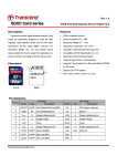
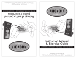
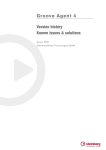
Rev.1.0, May. 2011
MMBTFxxGUBCA-xMExx
Samsung SD & MicroSD Card product family
SDA 3.0 specification compliant-Up to High Speed mode
datasheet
SAMSUNG ELECTRONICS RESERVES THE RIGHT TO CHANGE PRODUCTS, INFORMATION AND
SPECIFICATIONS WITHOUT NOTICE.
Products and specifications discussed herein are for reference purposes only. All information discussed
herein is provided on an "AS IS" basis, without warranties of any kind.
This document and all information discussed herein remain the sole and exclusive property of Samsung
Electronics. No license of any patent, copyright, mask work, trademark or any other intellectual property
right is granted by one party to the other party under this document, by implication, estoppel or otherwise.
Samsung products are not intended for use in life support, critical care, medical, safety equipment, or
similar applications where product failure could result in loss of life or personal or physical harm, or any
military or defense application, or any governmental procurement to which special terms or provisions
may apply.
For updates or additional information about Samsung products, contact your nearest Samsung office.
All brand names, trademarks and registered trademarks belong to their respective owners.
ⓒ 2011 Samsung Electronics Co., Ltd. All rights reserved.
-1-
MMBTFxxGWBCA-xMExx
Rev. 1.0
datasheet
SD Card
Revision History
Revision No.
1.0
History
1. Customer sample acquired
-2-
Draft Date
Remark
Editor
Jun, 02. 2011
Final
S.M.Lee
MMBTFxxGWBCA-xMExx
datasheet
Rev. 1.0
SD Card
Table Of Contents
1.0 INFORMATION ........................................................................................................................................................... 4
2.0 PRODUCT LINE-UP ................................................................................................................................................... 4
3.0 INTRODUCTION ........................................................................................................................................................ 5
3.1 General Description................................................................................................................................................. 5
3.2 System Features ..................................................................................................................................................... 5
3.3 System Block Diagram ............................................................................................................................................ 5
4.0 PRODUCT SPECIFICATION...................................................................................................................................... 6
4.1 Current Consumption .............................................................................................................................................. 6
4.2 System Performance ............................................................................................................................................... 6
4.2.1 Product Performance & Speed Class Information ............................................................................................ 6
4.2.2 Read, Write Timeout Error Conditions .............................................................................................................. 6
4.3 SD Mode Card Registers......................................................................................................................................... 7
4.3.1 OCR Register.................................................................................................................................................... 7
4.3.2 CID Register...................................................................................................................................................... 8
4.3.3 CSD Register (CSD Version 1.0) ...................................................................................................................... 9
4.3.4 CSD Register (CSD Version 2.0) ...................................................................................................................... 10
4.3.5 RCA Register .................................................................................................................................................... 10
4.3.6 SCR Register .................................................................................................................................................... 11
4.3.7 SD Status Register............................................................................................................................................ 12
4.4 SPI Mode Card Registers ........................................................................................................................................ 12
4.5 User Capacity .......................................................................................................................................................... 12
5.0 INTERFACE DESCRIPTION ...................................................................................................................................... 13
5.1 SD/microSD SD mode Bus Topology / SD/microSD SPI Bus Topology ................................................................. 13
5.2 Bus Protocol ............................................................................................................................................................ 14
5.2.1 SD Bus .............................................................................................................................................................. 14
5.2.2 SPI Bus ............................................................................................................................................................. 14
5.3 SD/microSD Card Pin Assignment .......................................................................................................................... 14
5.3.1 SD Card Pin Assignment .................................................................................................................................. 14
5.3.2 microSD Card Assignment................................................................................................................................ 15
5.4 Mechanical Specification ......................................................................................................................................... 16
5.4.1 Mechanical Form Factor of microSD................................................................................................................. 16
5.4.2 Mechanical Form Factor of SD Card................................................................................................................. 20
5.4.3 Electrical features, Environmental Reliability and Durability ............................................................................. 22
5.5 Electrical Interface ................................................................................................................................................... 23
5.5.1 Power Up .......................................................................................................................................................... 23
5.5.2 Reset Level Power Up ...................................................................................................................................... 24
5.5.3 Power Down and Power Cycle.......................................................................................................................... 24
5.5.4 Bus Operating Conditions for 3.3V Signaling.................................................................................................... 25
5.5.4.1 Threshold Level for High Voltage Range.................................................................................................... 25
5.5.4.2 Bus Signal Line Load.................................................................................................................................. 25
5.5.5 Bus Signal Levels.............................................................................................................................................. 26
5.5.6 Bus Timing (Default Mode) .............................................................................................................................. 27
5.5.7 Bus Timing (High-speed Mode) ........................................................................................................................ 28
6.0 SD/MICROSD CARD FUNCTIONAL DESCRIPTION ................................................................................................ 29
6.1 General.................................................................................................................................................................... 29
6.2 Card Identification Mode.......................................................................................................................................... 29
6.3 Clock Control ........................................................................................................................................................... 29
6.4 Cyclic Redundancy Code ........................................................................................................................................ 29
6.5 Command ................................................................................................................................................................ 29
6.6 Memory Array Partitioning ....................................................................................................................................... 30
6.7 Timings .................................................................................................................................................................... 31
6.8 Speed Class Specification ....................................................................................................................................... 31
6.9 Erase Timeout Calculation ...................................................................................................................................... 31
-3-
Rev. 1.0
datasheet
MMBTFxxGWBCA-xMExx
SD Card
1.0 INFORMATION
M X X X X X X X X X X X - X X X X X
1 2 3 4 5 6 7 8 9 10 11 12 13 14 15 16 17 18
1. Module: M
12. PCB Revision and Production site.
A : None (SEC)
B : 1st Rev. (SEC)
C : 2nd Rev. (SEC)
D : 3rd Rev. (SEC)
P : None (STS)
Q : 1st Rev. (STS)
R : 2nd Rev. (STS)
U : None(ATP)
V : 1st Rev.(ATP)
W : 2nd Rev.(ATP)
Y : None(SPIL)
2. Module Configuration
C : Flash Card (SLC)
E : Flash Card (OneNAND)
M : Flash Card (MLC)
3~4. Flash Density
64 : 64M
56 : 256M
5D : 512M DDP
1D : 1G DDP
2D : 2G DDP
8G : 8G
B3 : 32Gb 3bit
BA : 32Gb DDR
28 : 128M
2 : 512M
1G : 1G
2G : 2G
4G : 4G
AG : 16G
BG: 32Gb 2bit
BT : 32G(3Bit Toggle)
13. " - "
14. Packing Type
0 : With Label
1 : With Label/Contents
2 : No Label
3 : With Label Class2
4 : With Label Class4
5 : With Label Class6
6 : With Label Class10
7 : With Label UHS-I Speed Class1
A : None
B : Blue
D : Dark Black
G : Gray
H : White
M : Module Type
N : Navy Blue
P : Class2(No Label)
Q : Class4(No Label)
R : Class6(No Label)
S : Class10(No Label)
T : Metal Blue
W : Wine
5. Feature
R : microSD
F : SD
6~8. Card Density
008 : 8M Byte
032 : 32M Byte
064 : 64M Byte
128 : 128M Byte
256 : 256M Byte
512 : 512M Byte
02G : 2G Byte
08G : 8G Byte
32G : 32G Byte
016 : 16M Byte
048 : 48M Byte
096 : 96M Byte
192 : 192M Byte
384 : 384M Byte
01G : 1G Byte
04G : 4G Byte
16G : 16G Byte
9. Card Type
U : microSD
W : SD
10. Component Generation
M : 1st Generation
B : 3rd Generation
D : 5th Generation
11. Flash Package
C : CHIP
V : WSOP
15 ~ 16. Controller
ME: SS6651ACWWE
A : 2nd Generation
C : 4th Generation
E : 6th Generation
17 ~ 18. Customer Grade
" Customer List Reference "
Y : TSOP1
B : TBGA
2.0 PRODUCT LINE-UP
Model Number
Capacities
MMBTF04GWBCA-xMExx
4GB
MMBTF08GWBCA-xMExx
8GB
MMBTF16GWBCA-xMExx
16GB
-4-
Remarks
SD Card
(x : Refer to the Ordering Information)
MMBTFxxGWBCA-xMExx
Rev. 1.0
datasheet
SD Card
3.0 INTRODUCTION
3.1 General Description
The SD/microSD is a memory card that is specifically designed to meet the security, capacity, performance and enviroment requirements inherent in
newly emerging audio and video consumer electronic devices. The SD/microSD will include a copyright protection mechanism that complies with the
security of the SDMI standard and will be faster and capable for higher Memory capacity. The SD/microSD security system uses mutual authentication
and a "new ciper algorithm" to protect from illegal usage of the card content. A none secured access to the user’s own content is also available.
The SD/ microSD communication is based on an advanced 9 and 8-pin interface (SD:9pin, microSD:8pin)) designed to operate in at maximum operating
frequency of 208MHz and 2.7V ~ 3.6V voltage range with 2 Type signaling(1.8V & 3.3V)*. More detail informations on the interface, and mechanical
description is defined as a part of this specification.
* High Speed mode Limited on this Specification.
3.2 System Features
• Compliant with SD Memory Card Specifications PHYSICAL LAYER SPECIFICATION Version 3.00
- Based on SD Memory Card Specification 3.0 compatible Test Device.
- Bus speed only support up to High Speed Mode (3.3V signaling, frequency up to 50MHz)
• Targeted for portable and stationary applications
• Memory capacity:
1) Standard Capacity SD Memory Card(SDSC) : Up to and including 2 GB
2) High Capacity SD Memory Card(SDHC) : More than 2GB and up to and including 32GB
3) Extended Capacity SD Memory Card(SDXC) : More than 32GB and up to and including 2TB
• Voltage range:
High Voltage SD Memory Card – Operating voltage range: 2.7-3.6 V
• Designed for read-only and read/write cards.
• Bus Speed Mode
1) Default mode: Variable clock rate 0 - 25 MHz, up to 12.5 MB/sec interface speed (using 4 parallel data lines)
2) High-Speed mode: Variable clock rate 0 - 50 MHz, up to 25 MB/sec interface speed (using 4 parallel data lines)
• Switch function command supports High-Speed, and future functions
• Correction of memory field errors
• Card removal during read operation will never harm the content
• Content Protection Mechanism - Complies with highest security of SDMI standard.
• Password Protection of cards (CMD42 - LOCK_UNLOCK)
• Write Protect feature using mechanical switch
• Built-in write protection features (permanent and temporary)
• Card Detection (Insertion/Removal)
• Application specific commands
• Comfortable erase mechanism
• Weight : SD Card Max. 2.5g / microSD Card Max. 1g
3.3 System Block Diagram
<Host>
<SD / microSD Card>
Data
In/Out
SD / SPI
Interface
SD
Controller
Control
/ CLK
-5-
NAND
Flash
Rev. 1.0
datasheet
MMBTFxxGWBCA-xMExx
SD Card
4.0 PRODUCT SPECIFICATION
4.1 Current Consumption
This information table below provides current consumption of Samsung SD/microSD Card. Current consumption is measured by averaging over 1 second.
[Table 4-1] : Current Consumption Table
Mode
Max. Interface Frequency
Default Mode
25Mhz
High Speed Mode
50Mhz
Operations
Max.
Read
100mA
Write
Read
200mA
Write
NOTE:
Current consumption on each device can be varied by NAND Flash, . of chips, test conditions and Etc. For specific information, refer to Samsung SD/microSD Card Qualification report.
4.2 System Performance
4.2.1 Product Performance & Speed Class Information
Product Performance and Speed Class Informations are based on TestMetrix compliance Tool. Note that the performance measured by TestMetrix does
not represent real performance in various circumstances.
[Table 4-2] : Performance Information
Product Number
Write Performance (MB/s)
MMBTF04GWBCA-xMExx
7
MMBTF08GWBCA-xMExx
13
MMBTF16GWBCA-xMExx
13
Read Performance (MB/s)
Speed Class1
Class 4
24
Class 6
Class 6
NOTE:
1) Five Speed Classes are defined and indicate minimum performance of the cards in Speed Class Test Mode. Speed Class compliant SDA
Physical Layer Specification, Version 3.00
.Class 0 - These Class cards do not specify performance. It includes all the legacy cards prior to this specification, regardless of its performance
.Class 2 - is more than or equal to 2MB/s performance
.Class 4 - is more than or equal to 4MB/s performance
.Class 6 - is more than or equal to 6MB/s performance
.Class 10 - is more than or equal to 10MB/s performance
4.2.2 Read, Write Timeout Error Conditions
SEC SD/microSD Card shall complete the command within the time period defined as follows or give up and return and error message. If the host does
not get any response with the given timeout it should assume that the card is not going to respond and try recover. For more information, refer to Section
4.6 of the SDA Physical Layer Specification, Version 3.00
[Table 4-3] : Timeout Error Conditions
Timing
Max. Value
Block Read Access Time
100ms
Block Write Access Time
250ms(SDSC/SDHC), 500ms(SDXC)
1s
1
Initialization Time out(ACMD 41)
NOTE:
1) The host shall set ACMD41 timeout more than 1 second to abort repeat of issuing ACMD41 when the card does not indicate ready. The timeout count starts from the first
ACMD41 which is set voltage window in the argument.
-6-
MMBTFxxGWBCA-xMExx
datasheet
Rev. 1.0
SD Card
4.3 SD Mode Card Registers
Six registers are defined within the card interface: OCR, CID, CSD, RCA, DSR and SCR. These can be accessed only by corresponding commands. The
OCR, CID, CSD and SCR registers carry the card/content specific information, while the RCA and DSR registers are configuration registers storing actual
configuration parameters.
4.3.1 OCR Register
• The 32-bit operation conditions register stores the VDD voltage profile of the card. Additionally, this register includes status information bits.
•See Section 5.1 of the SDA Physical Layer Specification, Version 3.00 for more information.
[Table 4-4] : OCR Register Definition
OCR bit
VDD Voltage Window
OCR Value
0-3
reserved
0
4
reserved
0
5
reserved
0
6
reserved
0
7
reserved for Low Voltage Range
0
8
reserved
0
9
reserved
0
10
reserved
0
11
reserved
0
12
reserved
0
13
reserved
0
14
reserved
0
15
2.7 - 2.8
1
16
2.8 - 2.9
1
17
2.9 - 3.0
1
18
3.0 - 3.1
1
19
3.1 - 3.2
1
20
3.2 - 3.3
1
21
3.3 - 3.4
1
22
3.4 - 3.5
1
23
3.5 - 3.6
1
3
Switching to 1.8V Accepted (S18A)
0
24 - 29
reserved
0
30
Card Capacity Staus(CCS)1
-
31
Card power up status bit(busy)2
-
24
NOTE:
1) This bit is valid only when the card power up status bit is set.
2) This bit is set to LOW if the card has not finished the power up routine.
3) Only UHS-I card supports this bit.
-7-
Rev. 1.0
datasheet
MMBTFxxGWBCA-xMExx
SD Card
4.3.2 CID Register
The Card IDentification (CID) register is 128 bits wide. It contains the card identification information used during the card identification phase. Every individual Read/Write (RW) card shall have an unique identification number. It is programmed during manufacturing and cannot be changed by card hosts.
The structure of the CID register is defined in the following paragraphs:
[Table 4-5] : CID Register Fields
Name
Field
Type
Width
Manufacturer ID
MID
Binary
8
OEM/Application ID
OID
ASCII
16
Product name
PNM
ASCII
40
Product revision
PRV
BCD
8
Product serial number
PSN
Binary
32
Reserved
-
-
4
Manufacturing date
MDT
BCD
12
CRC7 checksum
CRC
Binary
7
not used, always ’1’
-
-
1
-8-
CID Value
4GB
8GB
16GB
CID Register Value can be provided by Customer Request
Rev. 1.0
datasheet
MMBTFxxGWBCA-xMExx
SD Card
4.3.3 CSD Register (CSD Version 1.0)
The Card-Specific Data register provides information on how to access the card contents. The CSD defines the data format, error correction type, maximum data access time, data transfer speed, whether the DSR register can be used etc. The programmable part of the register (entries marked by W or E,
see below) can be changed by CMD27. The type of the entries in the table below is coded as follows: R = readable, W(1) = writable once, W=multiple
writable.
[Table 4-6] : The CSD Register Fields (CSD Version 1.0)
Name
Field
Width
Cell
Type
CSD-slice
CSD structure
CSD_STRUCTURE
2
R
[127:126]
CSD Value
4GB
8GB
Version 1.0
Reserved
-
6
R
[125:120]
-
Data read access-time 1
TAAC
8
R
[119:112]
N/A
Data read access-time 2
in CLK cycles (NSAC*100)
NSAC
8
R
[111:104]
N/A
Max. Data transfer rate
TRAN_SPEED
8
R
[103:96]
N/A
Card command classes
CCC
12
R
[95:84]
N/A
Max. read data block length
READ_BL_LEN
4
R
[83:80]
N/A
Partial blocks for read allowed
READ_BL_PARTIAL
1
R
[79:79]
N/A
Write block misalignment
WRITE_BLK_MISALIGN
1
R
[78:78]
N/A
Read block misalignment
READ_BLK_MISALIGN
1
R
[77:77]
N/A
DSR implemented
DSR_IMP
1
R
[76:76]
N/A
Reserved
-
2
R
[75:74]
-
Device size
C_SIZE
12
R
[73:62]
N/A
Max. read current @ VDD min
VDD_R_CURR_MIN
3
R
[61:59]
N/A
Max. read current @ VDD max
VDD_R_CURR_MAX
3
R
[58:56]
N/A
Max. write current @ VDD min
VDD_W_CURR_MIN
3
R
[55:53]
N/A
Max. write current @ VDD max
VDD_W_CURR_MAX
3
R
[52:50]
N/A
Device size multiplier
C_SIZE_MULT
3
R
[49:47]
N/A
Erase single block enable
ERASE_BLK_EN
1
R
[46:46]
N/A
Erase sector size
SECTOR_SIZE
7
R
[45:39]
N/A
Write protect group size
WP_GRP_SIZE
7
R
[38:32]
N/A
Write protect group enable
WP_GRP_ENABLE
Reserved (Do Not Use)
1
R
[31:31]
N/A
2
R
[30:29]
-
Write speed factor
R2W_FACTOR
3
R
[28:26]
N/A
Max. write data block length
WRITE_BL_LEN
4
R
[25:22]
N/A
Partial blocks for write allowed
WRITE_BL_PARTIAL
1
R
[21:21]
N/A
Reserved
-
5
R
[20:16]
-
File format group
FILE_FORMAT_GRP
1
R/W(1)
[15:15]
N/A
Copy flag (OTP)
COPY
1
R/W(1)
[14:14]
N/A
Permanent write protection
PERM_WRITE_PROTECT
1
R/W(1)
[13:13]
N/A
Temporary write protection
TMP_WRITE_PROTECT
1
R/W
[12:12]
N/A
File format
FILE_FORMAT
Reserved
2
R/W(1)
[11:10]
N/A
2
R/W
[9:8]
-
CRC
CRC
7
R/W
[7:1]
N/A
Not used, always ’1’
-
1
-
[0:0]
-
-9-
16GB
Rev. 1.0
datasheet
MMBTFxxGWBCA-xMExx
SD Card
4.3.4 CSD Register (CSD Version 2.0)
The following Table shows Definition of the CSD Version 2.0 for the High Capacity SD Memory Card and Extended Capacity SD Memory Card. The following sections describe the CSD fields and the relevant data types for the High Capacity SD Memory Card.
CSD Version 2.0 is applied to only the High Capacity SD Memory Card. The field name in parenthesis is set to fixed value and indicates that the host is
not necessary to refer these fields. The fixed values enables host, which refers to these fields, to keep compatibility to CSD Version 1.0. The Cell Type
field is coded as follows: R = readable, W(1) = writable once, W = multiple writable.
[Table 4-7] : The CSD Register Fields (CSD Version 2.0)
CSD Value
Name
Field
Width
Cell
Type
CSD-slice
CSD structure
CSD_STRUCTURE
2
R
[127:126]
CSD Version 2.0
Reserved
-
6
R
[125:120]
-
Data read access-time
(TAAC)
8
R
[119:112]
1000.00 us
Data read access-time
in CLK cycles (NSAC*100)
(NSAC)
8
R
[111:104]
0 cycles
Max. Data transfer rate
(TRAN_SPEED)
8
R
[103:96]
25 Mbit/s or 50 Mbit/s
Card command classes
CCC
12
R
[95:84]
class 0 2 4 5 7 8 10
Max. read data block length
(READ_BL_LEN)
4
R
[83:80]
512 bytes
4GB
8GB
Partial blocks for read allowed
(READ_BL_PARTIAL)
1
R
[79:79]
0
Write block misalignment
(WRITE_BLK_MISALIGN)
1
R
[78:78]
0
Read block misalignment
(READ_BLK_MISALIGN)
1
R
[77:77]
0
DSR implemented
DSR_IMP
1
R
[76:76]
0
Reserved
-
6
R
[75:70]
Device size
C_SIZE
22
R
[69:48]
7579
15191
Reserved
-
1
R
[47:47]
-
Erase single block enable
(ERASE_BLK_EN)
1
R
[46:46]
1
Erase sector size
(SECTOR_SIZE)
7
R
[45:39]
128 blocks
Write protect group size
(WP_GRP_SIZE)
7
R
[38:32]
1 sectors
Write protect group enable
(WP_GRP_ENABLE)
1
R
[31:31]
0
Reserved
-
2
R
[30:29]
-
Write speed factor
(R2W_FACTOR)
3
R
[28:26]
4
Max. write data block length
(WRITE_BL_LEN)
4
R
[25:22]
512 bytes
Partial blocks for write allowed
(WRITE_BL_PARTIAL)
1
R
[21:21]
0
Reserved
-
5
R
[20:16]
-
File format group
(FILE_FORMAT_GRP)
1
R
[15:15]
0
Copy flag (OTP)
COPY
1
R/W(1)
[14:14]
0
Permanent write protection
PERM_WRITE_PROTECT
1
R/W(1)
[13:13]
0
Temporary write protection
TMP_WRITE_PROTECT
1
R/W
[12:12]
0
(FILE_FORMAT)
2
R
[11:10]
0
2
R
[9:8]
-
File format
Reserved
16GB
CRC
CRC
7
R/W
[7:1]
-
Not used, always ’1’
-
1
-
[0:0]
-
30531
4.3.5 RCA Register
The writable 16-bit relative card address register carries the card address that is published by the card during the card identification. This address is used
for the addressed host-card communication after the card identification procedure. The default value of the RCA register is 0x0000. The value 0x0000 is
reserved to set all cards into the Stand-by State with CMD7.
- 10 -
MMBTFxxGWBCA-xMExx
Rev. 1.0
datasheet
SD Card
4.3.6 SCR Register
In addition to the CSD register, there is another configuration register named SD CARD Configuration Register (SCR). SCR provides information on the
SD Card’s special features that were configured into the given card. The size of SCR register is 64bits. The register shall be set in the factory by the SD
Card manufacturer. The following table describes the SCR register content.
[Table 4-8] : The SCR Fields
SCR Value
Name
Field
Width
Cell
Type
SCR-slice
SCR structure
SCR_STRUCTURE
4
R
[63:60]
SCR Version 1.0
SD Memory Card - Spec. Version
SD_SPEC
4
R
[59:56]
Version 2.00 or Version 3.00
data_status_after erases
DATA_STAT_AFTER_ERASE
1
R
[55:55]
0
4GB
8GB
16GB
SD Security Support
SD_SECURITY
3
R
[54:52]
Version 2.00
DAT Bus widths supported
SD_BUS_WIDTHS
4
R
[51:48]
1 bit(DAT0) + 4 bit(DAT0-3)
Spec. Version 3.00 or Higher
SD_SPEC3
1
R
[47]
13
R
[46:34]
-
Reserved
Version 3.00
Command Support bits
CMD_SUPPORT
14
R
[33:32]
Not Supported
Reserved for manufacturer usage
-
32
R
[31:0]
-
- 11 -
Rev. 1.0
datasheet
MMBTFxxGWBCA-xMExx
SD Card
4.3.7 SD Status Register
The SD Status contains status bits that are related to the SD Memory Card proprietary features and may be used for future application specific usage. The
size of the SD Status is one data block of 512bit. The content of this register is transmitted to the Host over the DAT bus along with 16bit CRC. The SD
Status is sent to the host over the DAT bus if ACMD13 is sent (CMD55 followed with CMD13). ACMD13 can be sent to a card only in ’tran_state’ (card is
selected). SD Status structure is described in below. Unused reserved bits shall be set to 0.
[Table 4-9] : SD Status Register
Data
Value
Bits
Field
Cell
Type
511:510
DATA_BUS_WIDTH
SR
0x00
1bit width or 4bit width
509
SECURED_MODE
SR
0x00
-
508:502
4GB
8GB
16GB
4GB
8GB
16GB
Reserved for Security Functions (Refer to Part 3 Security Specification)
Reserved
501:496
495:480
SD_CARD_TYPE
SR
0x0000
479:448
SIZE_OF_PROTECTED_AREA
SR
0x2000000
447:440
SPEED_CLASS
SR
0x2
439:432
PERFORMANCE_MOVE
SR
0x2
431:428
AU_SIZE
SR
423:408
ERASE_SIZE
SR
0x10
16 AU
407:402
ERASE_TIMEOUT
SR
0x1
1sec
401:400
ERASE_OFFSET
SR
0x2
2sec
0x3000000
Regular SD RD/WR Card
0x4000000
-
0x3
Class 4
0x3
2 [MB/sec]
0x9
Class 6
3 [MB/sec]
4MB
Reserved
427:424
399:312
Reserved
311:0
Reserved for Manufacturer
NOTE:
Speed Class that supports Class 10 shall not use the Pm value stored in the SD Status to calculate performance in any fragmented AU. Class 10 Performance is defined only
for entirely free AUs
4.4 SPI Mode Card Registers
Unlike the SD Memory card protocol (where the register contents is sent as command response),reading the contents of the CSD and CID registers in
SPI mode is a simple read-block transaction. The card will respond with a standard response token followed by data block of 16 bytes suffixed with a 16bit CRC.
The data timeout for the CSD command cannot be set to the cards TAAC since this value is stored in the card‘s CSD. Therefore, the standard response
timeout value(NCR) is used for read latency of the CSD register.
4.5 User Capacity
This information table below provides user capacity of Samsung SD/microSD Card.
Product user density is based on SD Formatter 2.0 tool with FAT File system.
SD Formatter 2.0 software formats all SD Cards and SDHC Cards using a formatting program that complies with official SD memory card requirements.
Product Number
File System
Tot. Sector No.
7,745,536
3,965,714,432
FAT32
15,540,224
7,956,594,688
31,248,384
15,999,172,608
MMBTF04GWBCA-xMExx
MMBTF08GWBCA-xMExx
MMBTF16GWBCA-xMExx
User Capacity[Byte]
NOTE :
SD or SDHC Card file systems formatted with generic operating system formatting software do not comply with official SD memory card requirement and optimum performance
may not be experienced
- 12 -
Rev. 1.0
datasheet
MMBTFxxGWBCA-xMExx
SD Card
5.0 INTERFACE DESCRIPTION
5.1 SD/microSD SD mode Bus Topology / SD/microSD SPI Bus Topology
Host
CLK
VDD
VSS
D0~3(A)
CMD(A)
Host
CLK
VDD
VSS
CS
CS(A)
VDD
VSS
VDD
VSS
SD Memory
Card(A)
D0~D3, CMD
D0~D3, CMD
CLK
VDD
VSS
D0~3(B)
CMD(B)
VDD
VSS
CLK,
DataIN,
DataOut
D0~D3, CMD
SD Memory Card System Bus Topology
The SD/microSD Memory Card system defines two alternative communication protocols: SD and SPI. The host system can choose either one of
modes. The card detects which mode is requested by the host when the
reset command is received and expects all further communication to be in
the same communication mode. Common bus signals for multiple card
slots are not recommended. A single SD bus should connect a single SD
card. Where the host system supports a high-speed mode, a single SD bus
shall be connected to a single SD card.
The SD/microSD bus includes the following signals:
•
•
•
•
CS
CS(B)
SD Memory
Card(B)
CMD
: Bidirectional Command/Response signal
DAT0 - DAT3 : 4 Bidirectional data signals
CLK
: Host to card clock signal
VDD, VSS1, VSS2: Power and ground signals
The SD/microSD Card bus has a single master (application), multiple
slaves (cards), synchronous start topology (refer to Figure 5-2). Clock,
power and ground signals are common to all cards. Command (CMD) and
data (DAT0-DAT3) signals are dedicated to each card providing continues
point to point connection to all the cards.
During initialization process, commands are sent to each card individually,
allowing the application to detect the cards and assign logical addresses to
the physical slots. Data is always sent (received) to (from) each card individually. However, in order to simplify the handling of the card stack, after
initialization process, all commands may be sent concurrently to all cards.
Addressing information is provided in the command packet.
SD Memory
CARD(A)
(SPI mode)
CLK, DataIN, DataOut
SD Memory
CARD(B)
(SPI mode)
SD Memory Card system (SPI mode) Bus Topology
The SPI compatible communication mode of the SD/microSD Memory Card
is designed to communicate with a SPI channel, commonly found in various
microcontrollers in the market. The interface is selected during the first
reset command after power up and cannot be changed as long as the part
is powered on.
The SPI standard defines the physical link only, and not complete data
transfer protocol. The SD/microSD Card SPI implementation uses the same
command set of the SD mode. From the application point of view, the
advantage of the SPI mode is the capability of using an off-the-shelf host,
hence reducing the design-in effort to minimum. The disadvantage is the
loss of performance, relatively to the SD mode which enables the wide bus
option.
The SD/microSD Card SPI interface is compatible with SPI hosts available
on the market. As any other SPI device the SD/microSD Card SPI channel
consists the following four signals:
•
•
•
•
CS
: Host to card Chip Select signal
CLK
: Host to card clock signal
DataIN : Host to card data signal
DataOut: Card to host data signal
Another SPI common characteristic is byte transfers, which is implemented
in the card as well. All data tokens are multiples of bytes (8 bit) and always
byte aligned to the CS signal.
The card identification and addressing methods are replaced by a hardware
Chip Select (CS) signal. There are no broadcast commands. For every
command, a card (slave) is selected by asserting (active low) the CS signal
.
The CS signal must be continuously active for the duration of the SPI transSD Bus allows dynamic configuration of the number of data lines. After action (command, response and data). The only exception occurs during
power-up, be default, the SD/microSD Card will use only DAT0 for data card programming, when the host can de-assert the CS signal without
transfer. After initialization, the host can change the bus width(number of affecting the programming process.
active data lines). This feature allows and easy trade off between hardware
cost and system performance. Note that while DAT1-DAT3 are not in use,
the related Host’s DAT lines should be in tri-state (input mode). For SDIO
cards DAT1 and DAT2 are used for signaling.
- 13 -
Rev. 1.0
datasheet
MMBTFxxGWBCA-xMExx
SD Card
5.2 Bus Protocol
5.2.1 SD Bus
For more details, refer to Section 3.6.1 of the SDA Physical Layer Specification, Version 3.00
5.2.2 SPI Bus
For more details, refer to Chapter 7 of the SDA Physical Layer Specification, Version 3.00
5.3 SD/microSD Card Pin Assignment
5.3.1 SD Card Pin Assignment
1 2 3 4 5 6 7 8
9
wp
SD Memory
Card
Figure 5-1. SD Memory Card shape and interface (top view)
The SD Memory Card has the form factor 24 mm x 32 mm x 2.1 mm or 24 mm x 32 mm x 1.4 mm.
Figure5-1 shows the general shape of the shape and interface contacts of the SD Memory Card. The detailed physical dimensions and mechanical
description are given in section 5.4.
The following Table defines the card contacts:
[Table 5-1] : SD Memory Card Pad Assignment
Pin #
Name
Description
Type1
Name
SD Mode
Type
Description
SPI Mode
1
CD/DAT32
CS
I3
Chip Select (neg true)
2
CMD
PP
3
VSS1
S
Command/Response
DI
I
Data In
Supply voltage ground
VSS
S
Supply voltage ground
4
VDD
S
Supply voltage
VDD
S
Supply voltage
5
CLK
I
Clock
SCLK
I
Clock
6
VSS2
7
DAT0
S
Supply voltage ground
VSS2
S
Supply voltage ground
I/O/PP
Data Line [Bit 0]
DO
O/PP
Data Out
8
DAT14
I/O/PP
Data Line [Bit 1]
RSV
9
DAT25
I/O/PP
Data Line [Bit 2]
RSV
I/O/PP3
Card Detect /
Data Line [Bit 3]
NOTE:
1) S: power supply; I: input; O: output using push-pull drivers; PP: I/O using push-pull drivers;
2) The extended DAT lines (DAT1-DAT3) are input on power up. They start to operate as DAT lines after SET_BUS_WIDTH command.
The Host shall keep its own DAT1-DAT3 lines in input mode, as well, while they are not used.
3) At power up this line has a 50KOhm pull up enabled in the card. This resistor serves two functions Card detection and Mode Selection.
For Mode Selection, the host can drive the line high or let it be pulled high to select SD mode. If the host wants to select SPI mode it should drive the
line low. For Card detection, the host detects that the line is pulled high. This pull-up should be disconnected by the user, during regular data transfer,
with SET_CLR_CARD_DETECT (ACMD42) command
4) DAT1 line may be used as Interrupt Output (from the Card) in SDIO mode during all the times that it is not in use for data transfer operations
(refer to "SDIO Card Specification" for further details).
5) DAT2 line may be used as Read Wait signal in SDIO mode (refer to "SDIO Card Specification" for further details).
- 14 -
Rev. 1.0
datasheet
MMBTFxxGWBCA-xMExx
SD Card
Pin 8
Pin 7
Pin 6
Pin 5
Pin 4
Pin 3
Pin 2
Pin 1
5.3.2 microSD Card Assignment
Figure 5-2. Contact Area
[Table 5-2] : microSD Contact Pad Assignment
SD Mode
Pin #
Name
Type
1
DAT22.5
2
3
1
SPI Mode
1
Description
Name
I/O/PP
Data Line [Bit 2]
RSV
CD/DAT32
I/O/PP3
Card Detect /
Data Line [Bit 3]
CS
I3
Chip Select (neg true)
CMD
PP
Command/Response
DI
I
Data In
4
VDD
S
Supply voltage
VDD
S
Supply voltage
5
CLK
I
Clock
SCLK
I
Clock
Type
Description
Reserved
6
VSS
S
Supply voltage ground
VSS
S
Supply voltage ground
7
DAT0
I/O/PP
Data Line [Bit 0]
DO
O/PP
Data Out
8
DAT12.4
Data Line [Bit 1]
RSV4
I/O/PP
NOTE:
1) S: power supply; I: input; O: output using push-pull drivers; PP: I/O using push-pull drivers ;
2) The extended DAT lines (DAT1-DAT3) are input on power up. They start to operate as DAT lines after
SET_BUS_WIDTH command. The Host shall keep its own DAT1-DAT3 lines in input mode, as well,
while they are not used.
3) At power up this line has a 50KOhm pull up enabled in the card. This resistor serves two functions Card
detection and Mode Selection. For Mode Selection, the host can drive the line high or let it be pulled
high to select SD mode. If the host wants to select SPI mode it should drive the line low. For Card
detection, the host detects that the line is pulled high. This pull-up should be disconnected by the user,
during regular data transfer, with SET_CLR_CARD_DETECT (ACMD42)
4) DAT1 line may be used as Interrupt Output (from the Card) in SDIO mode during all the times that it
is not in use for data transfer operations (refer to "SDIO Card Specification" for further details).
5) DAT2 line may be used as Read Wait signal in SDIO mode (refer to "SDIO Card Specification" for further details).
- 15 -
Rev. 1.0
datasheet
MMBTFxxGWBCA-xMExx
SD Card
5.4 Mechanical Specification
This section describes the mechanical and electrical features, as well as SEC SD/microSD Card environmental reliability and durability specifications. For
more details you can refer to Chapter 8 of SDA Physical Layer Specification, Version 2.00 and SDA ,microSD Card Addendum, Section 3.0 Mechanical
Specification for microSD Memory Card.
5.4.1 Mechanical Form Factor of microSD
1
3
R20
ALL EDGES
C2
B4
A1
R3
R4
DETAIL A
135°
B1
R1
R2
C3
B
A
R19
R7
R11
R10
B3
B2
R6
R5
C
A
C1
VIEW A
B1
CONTACT
SURFACE
DETAIL A
Figure 5-3. Mechanical Description: Top View
- 16 -
Rev. 1.0
datasheet
MMBTFxxGWBCA-xMExx
SD Card
A3
A2
7- A4
8- A5
B7
B8
B5
B6
B10
R18
B11
A9
R17
B9
45°
A8
CL
A7
A6
Figure 5-4. : Mechanical Description: Bottom View
D1
D2
KEEP OUT AREA
D3
Figure 5-5. Mechanical Description: Keep Out Area
- 17 -
MMBTFxxGWBCA-xMExx
datasheet
Rev. 1.0
SD Card
0.75mm Minimum
Nonconductive Area in front
of all 8 contact pads
Figure 5-6. Nonconductive Area in Front of Contact Pad
Nonconductive Area,
on both sides of
microSD card
Figure 5-7. Nonconductive Area on Sides of Card
- 18 -
Rev. 1.0
datasheet
MMBTFxxGWBCA-xMExx
SD Card
[Table 5-3] : microSD Package: Dimensions
SYMBOL
A
A1
A2
A3
A4
A5
A6
A7
A8
A9
B
B1
B2
B3
B4
B5
B6
B7
B8
B9
B10
B11
C
C1
C2
C3
D1
D2
D3
R1
R2
R3
R4
R5
R6
R7
R10
R11
R17
R18
R19
R20
MIN
10.90
9.60
7.60
0.75
0.90
0.60
0.80
14.90
6.30
1.64
1.30
0.42
2.80
5.50
0.20
1.00
7.80
1.10
0.90
0.60
0.20
0.00
1.00
1.00
1.00
0.20
0.20
0.70
0.70
0.70
0.70
29.50
0.10
0.20
0.05
0.02
COMMON DIMENSIONS
NOM
11.00
9.70
3.85
7.70
1.10
0.80
0.70
15.00
6.40
1.84
1.50
0.52
2.90
0.30
1.10
7.90
1.20
1.00
0.70
0.30
0.40
0.40
0.80
0.80
0.80
0.80
30.00
0.20
0.20
0.20
0.40
-
NOTES:
1) DIMENSIONING AND TOLERTANCING PER ASME Y14.5M-1994.
2) DIMENSIONS ARE IN MILLIMETERS.
3) COPLANARITY IS ADDITIVE TO C1 MAX THICKNESS.
- 19 -
MAX
11.10
9.80
7.80
0.85
8.50
0.80
15.10
6.50
2.04
1.70
0.62
3.00
0.40
1.20
9.00
8.00
1.30
1.10
0.80
0.40
0.15
0.60
0.60
0.90
0.90
0.90
0.90
30.50
0.30
0.60
0.20
0.15
NOTE
BASIC
BASIC
datasheet
MMBTFxxGWBCA-xMExx
Rev. 1.0
SD Card
5.4.2 Mechanical Form Factor of SD Card
Min 1.5
Min 1.5
Min 3.4
Figure 5-8. Mechanical Description: Top View - Keep Out Area
- 20 -
Rev. 1.0
datasheet
MMBTFxxGWBCA-xMExx
SD Card
+0
22.5 -0.1
0.6
0.7
2.1+0.15
0.7
1.4+0.15
-0.1
1.4+0.2
0.2
Contoct Pad
Surface
8.125
Cord Body
Corner
-0.1
1.4+0.2
6 x 2.5 = 15
4
(4-R0.3)
3
4
5
6
7
7.8
8
VDD CLK Vss DAT0 DAT1
DAT2
0.3
2-R
9
2
6.7
LOCK
Position
0.75
32 ±0.1
7.5Min
11.5
10
7.65Mn
1
CD/ CMD Vss
DAT3
5.95Min
5.65Min
Contoct Pad
Surface
4
2-R0.5
±0.1
3-R1±0.1
3-R1±0.1
24 ±0.1
2-R0.5
General Tolerance ±0.15
Figure 5-9. Mechanical Description
- 21 -
0Min
Rev. 1.0
datasheet
MMBTFxxGWBCA-xMExx
SD Card
9.75
8.05
6 X 2.5 =
15
4 Min
6-1
1.1 Min
5.625
0.9 Min
1.4 Min
3
4
5
6
5Min
7 8
VDD CLK VssDAT0 DAT1
Lock
Position
14.5
9
DAT2
2
10.85
1
CD/ CMD Vss
DAR
7.8
11.45
0.2Min
1.6Max
2.3 ±0.1
7 Min
4 Max
0.25 Min
0.75
write
protet
write
enable
General Tolerance ±0.15
Figure 5-10. Mechanical Description: Bottom View
5.4.3 Electrical features, Environmental Reliability and Durability
SEC SD/microSD Card Electrical features, Environmental Reliabilities and Durabilities conform to SDA Physical Layer Specification Version 2.00, Section
8.1. For more details and informations of SEC SD/microSD Card Data, refer to Product Qualification Report.
- 22 -
MMBTFxxGWBCA-xMExx
Rev. 1.0
datasheet
SD Card
5.5 Electrical Interface
The following sections provide valuable information about the electrical interface. See Chapter 6 of the SDA Physical Layer Specification, Version 3.00 for more detail information.
5.5.1 Power Up
The power-up of the SD/microSD Card bus is handled locally in each SD Card and in the host
Supply voltage
VDD max
Host supply voltage
Valid voltage range for
all commands
VDD min
Power up time
Time out value for
initialization process = 1Sec
End of first ACMD41 to card ready
Supply ramp up time
Initialization sequence
CMD0
CMD8
ACMD NCC
41
ACMD
41
NCC
ACMD
41
time
NCC
CMD2
Optional repetitons of ACMD41
until no cards are responding
with busy bit set
Initialization delay:
The maximum of
1 msec, 74 clock cycles
and supply ramp up time
Figure 5-11. Power-up Diagram
.• Power up time is defined as voltage rising time from 0 volt to VDD(min.) and depends on application parameters such as the maximum number of
SD Cards, the bus length and the characteristic of the power supply unit.
• Supply ramp up time provides the time that the power is built up to the operating level (the host supply voltage) and the time to wait until the SD card
can accept the first command,
• The host shall supply power to the card so that the voltage is reached to VDD(min.) within 250ms and start to supply at least 74 SD clocks to the
SD card with keeping CMD line to high. In case of SPI mode, CS shall be held to high during 74 clock cycles.
• After power up (including hot insertion, i.e. inserting a card when the bus is operating) the SD Card enters the idle state. In case of SD host, CMD0 is
not necessary. In case of SPI host, CMD0 shall be the first command to send the card to SPI mode.
• CMD8 is newly added in the Physical Layer Specification Version 2.00 to support multiple voltage ranges and used to check whether the card supports
supplied voltage. The version 2.00 host shall issue CMD8 and verify voltage before card initialization. The host that does not support CMD8 shall supply
high voltage range.
• ACMD41 is a synchronization command used to negotiate the operation voltage range and to poll the cards until they are out of their power-up
sequence. In case the host system connects multiple cards, the host shall check that all cards satisfy the supplied voltage. Otherwise, the host should
select one of the cards and initialize.
- 23 -
MMBTFxxGWBCA-xMExx
Rev. 1.0
datasheet
SD Card
5.5.2 Reset Level Power Up
Host needs to keep power line level less than 0.5V and more than 1ms before power ramp up.
VDD Supply
Voltage
3.6V
VDD max
Stable Supply voltage
Operating Supply Range
2.7V
VDD min
0.5V Power On/Cycle
level/duration
1msec
Time(not to scale)
CMD0
Power ramp up
Initialization delay The
maximum of 1msec, 74 clock
cycles and supply up time
Figure 5-12. change of Figure for power up
• To assure a reliable SD Card hard reset of Power On and Power Cycle, Voltage level shall be below 0.5V and Time duration shall be at least 1ms.
• The power ramp up time is defined from 0.5V threshold level up to the operating supply voltage which is stable between VDD(min.) and VDD(max.) and
host can supply SDCLK.
Followings are recommendation of Power ramp up:
(1) Voltage of power ramp up should be monotonic as much as possible.
(2) The minimum ramp up time should be 0.1ms.
(3) The maximum ramp up time should be 35ms for 2.7~3.6V power supply.
5.5.3 Power Down and Power Cycle
• When the host shuts down the power, the card VDD shall be lowered to less than 0.5Volt for a minimum period of 1ms. During power down, DAT, CMD,
and CLK should be disconnected or driven to logical 0 by the host to avoid a situation that the operating current is drawn through the signal lines.
• If the host needs to change the operating voltage, a power cycle is required. Power cycle means the power is turned off and supplied again. Power cycle
is also needed for accessing cards that are already in Inactive State. To create a power cycle the host shall follow the power down description before
power up the card (i.e. the card VDD shall be once lowered to less than 0.5Volt for a minimum period of 1ms).
- 24 -
Rev. 1.0
datasheet
MMBTFxxGWBCA-xMExx
SD Card
5.5.4 Bus Operating Conditions for 3.3V Signaling
SPI Mode bus operating conditions are identical to SD Card mode bus operating conditions.
5.5.4.1 Threshold Level for High Voltage Range
[Table 5-4] : Threshold Level for High Voltage
Parameter
Symbol
Min
Max.
Unit
Supply Voltage
VDD
2.7
3.6
V
Output High Voltage
VOH
0.75*VDD
Output Low Voltage
VOL
Input High Voltage
VIH
Input Low Voltage
VIL
V
IOH = -2mA VDD min
0.125*VDD
V
IOL = 2mA VDD min
0.625*VDD
VDD+0.3
V
Vss-0.3
0.25 *VDD
V
250
ms
=
Power Up Time
Remark
From 0V to VDD min
5.5.4.2 Bus Signal Line Load
The total capacitance of the SD Memory Card bus is the sum of the bus host capacitance CHOST, the bus capacitance CBUS itself and the capacitance
CCARD of each card connected to this line:
Total bus capacitance =
CHOST + CBUS + N * CCARD
Where N is the number of connected cards.
[Table 5-5] : Bus Operating Conditions - Signal Line’s Load
Parameter
Pull-up resistance
Total bus capacitance for each signal line
Capacitance of the card for each siginal pin
Symbol
Min
Max.
Unit
Remark
RCMD
RDAT
10
100
KOhm
to prevent bus floating
CL
40
pF
1 card
CHOST+CBUS shall
not exceed 30 pF
CCARD
10
pF
-
16
nH
fPP <= 20 MHz
90
KOhm
May be used for card detection
5
uF
To Prevent inrush current
Maximum signal line inductance
Pull-up resistance inside card (pin1)
RDAT3
Capacity Connected to Power Line
CC
10
Note that the total capacitance of CMD and DAT lines will be consist of CHOST, CBUS and one CCARD only because they are connected separately to the SD
Memory Card host.
Host should consider total bus capacitance for each signal as the sum of CHOST, CBUS, and CCARD, these parameters are defined by per signal. The host
can determine CHOST and CBUS so that total bus capacitance is less than the card estimated capacitance load (CL=40 pF). The SD Memory Card guarantees its bus timing when total bus capacitance is less than maximum value of CL (40 pF). To limit inrush current caused by host insertion, card maximum
capacitance between VDD - VSS is defined as 5uF. To support host hot insertion, the host should consider decoupling capacitor connected to power line.
As SD/microSD card Cc is 5uF(Max.), 45uF(min.) is recommended for Decoupling capacitor. For more details, please refer to Appendix E of the SDA
Physical Layer Specification 3.00.
- 25 -
Rev. 1.0
datasheet
MMBTFxxGWBCA-xMExx
SD Card
5.5.5 Bus Signal Levels
As the bus can be supplied with a variable supply voltage, all signal levels are related to the supply voltage.
Supply Voltage
VDD
Input
High Level
Output
High Level
VOH
VIH
Undefined
VIL
Input
Low Level
VOL
VSS
Output
Low Level
Time
Figure 5-13. Bus Signal Levels
To meet the requirements of the JEDEC specification JESD8-1A and JESD8-7, the card input and output voltages shall be within the specified ranges
shown in Table 5-2 for any VDD of the allowed voltage range.
- 26 -
Rev. 1.0
datasheet
MMBTFxxGWBCA-xMExx
SD Card
5.5.6 Bus Timing (Default Mode)
fPP
tWL
tWH
VIH
Clock
VIL
tTLH
tTHL
tISU
tIH
VIH
VIL
VOH
Output
VOL
tODLY (min)
tODLY(max)
Shaded areas are not valid
Figure 5-14. Timing diagram data input/output referenced to clock (Default)
[Table 5-6] : Bus Timing - Parameter Values (Default)
Parameter
Symbol
Min
Max.
Unit
Remark
Clock CLK ( All values are referred to min. (VIH) and max. (VIL )
Clock frequency Data Transfer Mode
fPP
0
25
MHz
CCARD <= 10 pF (1 card)
400
kHz
CCARD <= 10 pF (1 card)
1)
Clock frequency Identification Mode
fOD
0 / 100
Clock low time
tWL
10
ns
CCARD <= 10 pF (1 card‘s)
Clock high time
tWH
10
ns
CCARD <= 10 pF (1 card)
Clock rise time
tTLH
10
ns
CCARD <= 10 pF (1 card)
Clock fall time
tTHL
10
ns
CCARD <= 10 pF (1 card)
Inputs CMD, DAT (referenced to CLK)
Input set-up time
tISU
5
ns
CCARD <= 10 pF (1 card)
Input hold time
tIH
5
ns
CCARD <= 10 pF (1 card)
Outputs CMD, DAT (referenced to CLK)
Output delay time during Data Transfer Mode
tODLY
0
14
ns
CL <= 40 pF (1 card)
Output delay time during Identification Mode
tODLY
0
50
ns
CL<= 40 pF (1 card)
NOTE:
1) OHz means to stop the clock. The given minimum frequency range is for cases where a continuous clock is required
- 27 -
Rev. 1.0
datasheet
MMBTFxxGWBCA-xMExx
SD Card
5.5.7 Bus Timing (High-speed Mode)
fPP
tWH
tWL
50%VDD
VIH
Clock
VIL
tTHL
tISU
tTLH
tIH
VIH
Input
VIL
VOH
Output
VOL
tOH
tODLY
Shaded areas are not valid
Figure 5-15. Timing Diagram data Input/Output Refrenced to Clock (High-Speed)
[Table 5-7] : Bus Timing - Parameter Values (High-Speed)
Parameter
Symbol
Min
Max.
Unit
Remark
Clock CLK ( All values are referred to min. (VIH) and max. (VIL )
MHz
CCARD <= 10 pF (1 card)
7
ns
CCARD <= 10 pF (1 card)
7
ns
CCARD <= 10 pF (1 card)
3
ns
CCARD <= 10 pF (1 card)
3
ns
CCARD <= 10 pF (1 card)
Clock frequency Data Transfer Mode
fPP
0
Clock low time
tWL
Clock high time
tWH
Clock rise time
tTLH
Clock fall time
tTHL
50
Inputs CMD, DAT (referenced to CLK)
Input set-up time
tISU
6
ns
CCARD <= 10 pF (1 card)
Input hold time
tIH
2
ns
CCARD <= 10 pF (1 card)
ns
CL <= 40 pF (1 card)
ns
CL <= 15 pF (1 card)
pF
1 card
Outputs CMD, DAT (referenced to CLK)
Output delay time during Data Transfer Mode
tODLY
Output Hold time
tOH
Total Systme capacitance for each line1)
CL
NOTE:
1) In order to satisfy severe timing, host shall drive only one card.
- 28 -
14
2.5
40
MMBTFxxGWBCA-xMExx
datasheet
Rev. 1.0
SD Card
6.0 SD/MICROSD CARD FUNCTIONAL DESCRIPTION
6.1 General
SEC SD/microSD Card Functional Description contained in this chapter; Section 6.2~6.14; basically, comfort to SDA Physical Layer Specification, Version
3.00. See Chapter 4 of the SDA Physical Layer Specification, Version 3.00 for detail information and guide.
6.2 Card Identification Mode
While in Card Identification mode the host resets all the cards that are in card identification mode, validates operation voltage range, identifies cards and
asks them to publish Relative Card Address(RCA). This operation is done to each card separately on its own CMD line. Refer to Section 4.2 of the SDA
Physical Layer Specification, Version 3.00 for detail information and guide1)
NOTE :
1) The products on this specification does not support UHS-1 mode. For correct identification flow, please refer to Section 4.2 of the SDA Physical Layer Specification, Version
2.00.
6.3 Clock Control
The SD/microSD Memory Card bus clock signal can be used by the host to change the cards to energy saving mode or to control the data flow(to avoid
under-run or over-run conditions) on the bus. Refer to Section 4.4 of the SDA Physical Layer Specification, Version 3.00 for detail information and guide
6.4 Cyclic Redundancy Code
The CRC is intended for protecting SD Card commands, responses and data transfer against transmission errors on the SD Card bus. One CRC is generated for every command and checked for every response on the CMD line. For data blocks one CRC per transferred block, per data line, is generated.
The CRC is generated and checked as described in the Section 4.5 of the SDA Physical Layer Specification, Version 3.0
6.5 Command
There are four kinds of commands defined to control the SD Card:
* Broadcast commands (bc), no response - The broadcast feature is only if all the CMD lines are connected together
in the host. If they are separated then each card will accept it separately on his turn.
* Broadcast commands with response (bcr) - response from all cards simultaneously. Since there is no Open Drain
mode in SD Card, this type of command is used only if all the CMD lines are separated. The command will
be accepted and responded to by every card seperately.
* Addressed (point-to-point) commands (ac) - no data transfer on DAT lines
* Addressed (point-to-point) data transfer commands (adtc), data transfer on DAT lines
All commands and responses are sent over the CMD line of the SD Card bus. The command transmission always starts with the left bit of the bitstring corresponding to the command code word. For more details, refer to the Section 4.7 of the SDA Physical Layer Specification, Version 3.0.
NOTE:
Limited Vendor CMD information, only for certain customer and application, can be provided under appropriate purpose of usage.
- 29 -
datasheet
MMBTFxxGWBCA-xMExx
Rev. 1.0
SD Card
6.6 Memory Array Partitioning
The basic unit of data transfer to/from the SD Card is one byte. All data transfer operations which require a block size always define block lengths as integer multiples of bytes. Some special functions need other partition granularity.
SD Memory Card
WP Group 1
Sector 1
Block 1 Block 2 Block 3 Block n
Sector 2
Sector 3
Sector m
WP Group 2
WP Group K
Figure 6-1: Write Protection Hierarchy
For block oriented commands, the following definition is used:
• Block: is the unit that is related to the block oriented read and write commands. Its size is the number of bytes that will be transferred when one block
command is sent by the host. The size of a block is either programmable or fixed. The information about allowed block sizes and the programmability
is stored in the CSD.
• For devices that have erasable memory cells, special erase commands are defined. The granularity of the erasable units is in general not the same as
for the block oriented commands:
• Sector: is the unit that is related to the erase commands. Its size is the number of blocks that will be erased in one portion. The size of a sector is fixed
for each device. The information about the sector size (in blocks) is stored in the CSD. Note that if the card specifies AU size, sector size should
be ignored.
• AU (Allocation Unit): is a physical boundary of the card and consists of one or more blocks and its size depends on each card. The maximum AU size
is defined for memory capacity. Furthermore AU is the minimal unit in which the card guarantees its performance for devices which complies with Speed
Class Specification. The information about the size and the Speed Class are stored in the SD Status. AU is also used to calculate the erase timeout.
• WP-Group: is the minimal unit that may have individual write protection for devices which support write-protected group. Its size is the number of groups
that will be write-protected by one bit. The size of a WP-group is fixed for each device. The information about the size is stored in the CSD.
The High Capacity SD Memory Card does not support the write protect group command.
- 30 -
MMBTFxxGWBCA-xMExx
datasheet
6.7 Timings
Refer to Section 4.12 of the SDA Physical Layer Specification, Version 3.00 for detail information and guide1)
NOTE :
1) The products on this specification does not support UHS-1 mode.
6.8 Speed Class Specification
Refer to Section 4.13 of the SDA Physical Layer Specification, Version 3.00 for detail information and guide1)
NOTE :
1)The products on this specification does not support UHS-1 mode.
6.9 Erase Timeout Calculation
Refer to Section 4.14 of the SDA Physical Layer Specification, Version 3.00 for detail information and guide1)
NOTE :
1) The products on this specification does not support UHS-1 mode.
- 31 -
Rev. 1.0
SD Card