1
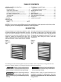
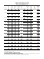
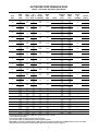
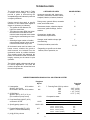
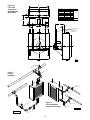
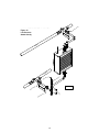
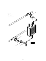
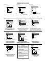
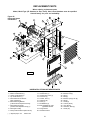
HIM-16
INSTALLATION INSTRUCTIONS & PARTS LIST
HORIZONTAL STEAM AND HOT WATER UNIT HEATERS
ATTENTION: READ THIS MANUAL AND ALL LABELS ATTACHED TO THE UNIT CAREFULLY BEFORE
ATTEMPTING TO INSTALL, OPERATE OR SERVICE THESE UNITS! CHECK UNIT DATA PLATE FOR TYPE
OF GAS AND ELECTRICAL SPECIFICATIONS AND MAKE CERTAIN THAT THESE AGREE WITH THOSE AT
POINT OF INSTALLATION. RECORD THE UNIT MODEL AND SERIAL No.(s) IN THE SPACE PROVIDED.
RETAIN FOR FUTURE REFERENCE.
Model No.
Serial No.
Improper installation, adjustment, alteration,
service or maintenance can cause property damage,
injury or death. Read the installation, operating and
maintenance instructions thoroughly before installing or
servicing this equipment.
INSTALLER’S RESPONSIBILITY
Installer Please Note: This equipment has been tested and
inspected. It has been shipped free from defects from our
factory. However, during shipment and installation, problems
such as loose wires, leaks or loose fasteners may occur. It is
the installer’s responsibility to inspect and correct any
problems that may be found.
RECEIVING INSTRUCTIONS
Inspect shipment immediately when received to determine if
any damage has occurred to the unit during shipment. After
the unit has been uncrated, check for any visible damage to
the unit. Turn fan by hand to determine if damage has occurred.
If any damage is found, the consignee should sign the bill of
lading indicating such damage and immediately file claim for
damage with the transportation company.
260 NORTH ELM ST.
WESTFIELD, MA 01085
08/12
J30-05404
TABLE OF CONTENTS
GENERAL SAFETY INFORMATION .......................... 3
SPECIFICATIONS
Dimensional Data .................................................. 4
Steam Performance Data ....................................... 5
Steam Calculations & Correction Factors ............... 6
Hot Water Performance Data ................................. 7
Hot Water Calculations & Correction Factors ........ 8
Technical Data ....................................................... 9
Motor Data ........................................................... 10
LOCATION ................................................................ 11
INSTALLATION
Unit Mounting ....................................................... 12
Piping ...............................................................12-16
ELECTRICAL CONNECTIONS ................................ 17
Operation ............................................................. 17
Thermostat Wiring and Location .......................... 17
WIRING INSTALLATION .......................................... 18
OPTIONS ................................................................. 19
MAINTENANCE ....................................................... 20
REPLACEMENT PARTS .......................................... 21
TROUBLESHOOTING GUIDE .................................. 22
WARRANTY .............................................................. 23
INSPECTION SHEET................................................ 24
NOTICE: It is the owner’s responsibility to provide any scaffolding or other apparatus required to perform
emergency service or annual/periodic maintenance to this equipment.
DESCRIPTION
Horizontal hydronic unit heaters are available in both
serpentine and header type units. Serpentine units offer
outputs from 8,030 to 35,900 BTU’s (2.4 to 10.5 kW) and
are ideal for hot water (only) installations with limited
clearances. Header type horizontal units range from
18,000 to 360,000 (5.3 to 105.5 kW) and can operate
with either hot water or steam. Both units are furnished
with totally enclosed motors, with explosion proof motors
as optional on header types. The designs are certified
by ETL. Do not alter these units in any way and do
not attach any ductwork to the units. If you have
any questions after reading this manual, contact the
manufacturer.
Figure 1
Serpentine
Type
Figure 2
Header
Type
The following terms are used throughout this manual, in addition to ETL requirements, to bring attention to the
presence of potential hazards or to important information concerning the product:
Indicates an imminently hazardous
situation which, if not avoided, will result in death,
serious injury or substantial property damage.
Indicates an imminently hazardous
situation which, if not avoided, may result in minor
injury or property damage.
Indicates an imminently hazardous
situation which, if not avoided, could result in
death, serious injury or substantial property
damage.
NOTICE: Used to notify of special instructions on
installation, operation or maintenance which are
important to equipment but not related to personal
injury hazards.
2
GENERAL SAFETY INFORMATION
Do not insert fingers or foreign objects into the heater
or its air moving device. Do not block or tamper with the
heater in any manner while in operation or just after it
has been turned off, as some parts may be hot enough
to cause injury.
Failure to comply with the general
safety information may result in extensive
property damage, severe personal injury or death.
Do not alter the unit heater in any
way or damage to the unit and/or severe personal
injury or death may occur!
To meet ETL and OSHA requirements, units
mounted below 8 feet (2.4m) from the floor must be
equipped with an OSHA fan guard.
Disconnect all power supplies
before installing or servicing the heater. If the
power disconnect is out of sight, lock it in the
open position and tag it to prevent unexpected
application of power. Failure to do so could result
in fatal electric shock, or severe personal injury.
It is good practice to have a shutoff switch on the
electrical power lines controlling the heater. Whenever a
unit is serviced, shut power off to the unit.
Since these units are installed in most instances higher
than 8 feet (2.4m), proper type of ladders or scaffolding
should be used, as set up by OSHA requirements (see
Notice on page 2).
Insure that all power sources
conform to the requirements of the unit heater
or damage to the unit will result!
In industrial plants, professional maintenance crews
should service this equipment.
Follow installation instructions CAREFULLY to avoid
creating unsafe conditions. All external wiring must
conform to applicable current local codes, and to the
latest edition of the National Electric Code ANSI/NFPA
No. 70. In Canada, all external wiring must conform
to the Canadian Electric Code, Part 1 CSA Standard
C22.1 All wiring should be done and checked by a
qualified electrician using copper wire only. All steam
and hot water connections should be made and leaktested by a suitably qualified individual, per instructions
in this manual. Also follow procedures listed on the “Unit
Equipment Start-Up Sheet” located in this manual.
All Horizontal Unit Heaters are shipped fully assembled
and may be used for steam or hot water applications.
Coils are factory tested at 250 psig (1723.5 kg).
Each unit is packaged individually and marked for proper
identification. Use normal care in handling and during
installation to prevent damage to the coils fins, fan and
casing.
Unless otherwise specified, the following conversions
may be used for calculating SI unit measurements:
1 inch water column = 0.249 kPa
1 foot = 0.305 m
meter/second = FPM ÷ 196.8
1 inch = 25.4 mm
1 psig = 6.894 kPa liter/second = CFM x 0.472
1 pound = 0.453 kg 1000 Btu per hour = 0.293 kW
1 gallon = 3.785 L 1000 Btu/Cu. Ft. = 37.5 MJ/m3
1 cubic foot = 0.028 m3
Make certain that the power source conforms to the
electrical requirements of the heater.
Do not depend upon a thermostat
or other switch as sole means of disconnecting
power when installing or servicing heater. Always
disconnect power at main circuit breaker as
described above. Failure to do so could result in
fatal electric shock.
Special attention must be given to any grounding
information pertaining to this heater. To prevent the
risk of electrocution, the heater must be securely and
adequately grounded. This should be accomplished by
connecting a grounded conductor between the service
panel and the heater. To ensure a proper ground,
the grounding means must be tested by a qualified
electrician.
3
DIMENSIONAL DATA
Figure 3 – Serpentine Type
Models 108A, 118A, 125A, 136A
Figure 4 – Header Type
Models 18 thru 360
NOTE: Motors are totally enclosed, thermally protected, sleeve bearing, with 2"(h) x 4"(w) conduit connection boxes. 3/8-16 nutserts are
attached to enclosure for balanced hanging.
Table 1 – Figure 3 Serpentine Models
MODEL
108A
118A
125A
136A
W
inches (mm)
18 (457)
18 (457)
18 (457)
20½ (521)
H
inches (mm)
16 (406)
16 (406)
16 (406)
18½ (470)
A
inches (mm)
167⁄32 (412)
167⁄32 (412)
167⁄32 (412)
1822⁄32 (475)
B
inches (mm)
11¼ (286)
11¼ (286)
11¼ (286)
13¾ (349)
C
inches (mm)
4¼ (108)
4¼ (108)
4¼ (108)
511⁄16 (144)
NO.
OF
LOUVERS
NOM.
FAN DIAM.
inches (mm)
APPROX.
SHIP WT.
lbs. (kg)
5
5
5
6
9 (229)
10 (254)
10 (254)
12 (305)
22 (10.0)
24 (10.9)
25 (11.3)
31 (14.0)
Table 2 – Figure 4 Header Models
MODEL
18
24
36
48
60
72
84
96
108
120
132
144
156
180
204
240
280
300
360
A
B
C
D
E
F
G*
H*
J
K
L
M
N
inches
(mm)
inches
(mm)
inches
(mm)
inches
(mm)
inches
(mm)
inches
(mm)
inches
(mm)
inches
(mm)
inches
(mm)
inches
(mm)
inches
(mm)
inches
(mm)
inches
(mm)
145⁄8
(371)
145⁄8
(371)
171⁄8
(435)
171⁄8
(435)
183⁄8
(467)
207⁄8
(530)
195⁄8
(498)
207⁄8
(530)
233⁄8
(594)
233⁄8
(594)
245⁄8
(625)
277⁄8
(708)
277⁄8
(708)
333⁄8
(848)
75⁄16
(186)
75⁄16
(186)
89⁄16
(217)
89⁄16
(217)
93⁄16
(233)
107⁄16
(265)
913⁄16
(249)
107⁄16
(265)
1111⁄16
(297)
1111⁄16
(297)
125⁄16
(313)
1315⁄16
(354)
1315⁄16
(354)
1611⁄16
(424)
15
(381)
18
(457)
20½
(521)
20½
(521)
21¾
(552)
24¼
(616)
24
(610)
25¼
(641)
27¾
(705)
27¾
(705)
29
(737)
30¼
(768)
30¼
(768)
37¾
(959)
7½
(191)
9
(229)
10¼
(260)
10¼
(260)
107⁄8
(276)
121⁄8
(308)
12
(305)
125⁄8
(321)
137⁄8
(352)
137⁄8
(352)
14½
(368)
151⁄8
(384)
151⁄8
(384)
187⁄8
(479)
61⁄8
(156)
61⁄8
(156)
57⁄8
(149)
57⁄8
(149)
6
(152)
61⁄8
(156)
65⁄16
(160)
65⁄16
(160)
65⁄16
(160)
65⁄16
(160)
63⁄8
(162)
81⁄8
(206)
81⁄8
(206)
9
(229)
215⁄16
(75)
215⁄16
(75)
215⁄16
(75)
215⁄16
(75)
215⁄16
(75)
215⁄16
(75)
33⁄16
(81)
33⁄16
(81)
33⁄16
(81)
33⁄16
(81)
33⁄16
(81)
33⁄16
(81)
33⁄16
(81)
33⁄16
(81)
3¼
93⁄8
(83) (238)
3¼
93⁄8
(83) (238)
511⁄16 117⁄16
(144) (291)
51⁄16 1015⁄16
(129) (278)
51⁄16 111⁄16
(129) (281)
511⁄16 1113⁄16
(144) (300)
7½ 1313⁄16
(191) (351)
13
611⁄16
(170) (330)
75⁄8
14
(194) (356)
77⁄16
13¾
(194) (349)
77⁄16
13¾
(194) (349)
57⁄8
14
(149) (356)
17¾
95⁄8
(244) (451)
185⁄8
95⁄8
(244) (473)
12¼
(311)
12¼
(311)
14¾
(375)
14¾
(375)
16
(406)
18½
(470)
17¼
(438)
18½
(470)
21
(533)
21
(533)
22¼
(565)
25½
(648)
25½
(648)
31
(787)
9½
(241)
12½
(318)
15
(381)
15
(381)
16¼
(413)
18¾
(476)
17½
(445)
18¾
(476)
21¼
(540)
21¼
(540)
22½
(572)
23¾
(603)
23¾
(603)
31¼
(794)
1¼
(32)
1¼
(32)
1¼
(32)
1¼
(32)
1¼
(32)
1¼
(32)
1½
(38)
1½
(38)
1½
(38)
1½
(38)
1½
(38)
2
(51)
2
(51)
2
(51)
2¼
(57)
2¼
(57)
1¾
(44)
1¾
(44)
1¾
(44)
1¾
(44)
1¾
(44)
1¾
(44)
1¾
(44)
1¾
(44)
1¾
(44)
1¾
(44)
1¾
(44)
1¾
(44)
127⁄8
(327)
127⁄8
(327)
153⁄8
(391)
153⁄8
(391)
165⁄8
(422)
191⁄8
(486)
177⁄8
(454)
191⁄8
(486)
215⁄8
(549)
215⁄8
(549)
227⁄8
(581)
261⁄8
(664)
261⁄8
(664)
315⁄8
(803)
NO.
OF
LOUVERS
4
5
6
6
7
8
8
8
9
9
9
10
10
13
NOM. FAN
DIAM.
inches (mm)
APPROX.
SHIP WT.
lbs. (kg)
9
(229)
10
(254)
12
(305)
12
(305)
14
(356)
14
(356)
16
(406)
18
(457)
18
(457)
18
(457)
18
(457)
20
(508)
20
(508)
24
(610)
26
(11.8)
30
(13.6)
41
(18.6)
41
(18.6)
44
(19.9)
47
(21.3)
49
(22.2)
59
(26.7)
74
(33.5)
74
(33.5)
90
(40.8)
143
(65)
154
(70)
203
(92)
* Applies to standard motor with standard fan guard. When optional motors or OSHA fan guards are requested, dimensions will vary according to
the substitutions made.
NOTES: 1. OSHA guard standard on all serpentine models and header models 18 thru 48 supplied with 1 phase motors (dimensions shown in tables).
2. Standard motor and standard guard shown.
3. All 3 phase and explosion proof motors are shelf mounted.
4
STEAM PERFORMANCE DATA
Table 3 - Header Type Models only
Unit
Size
18
24
36
48
60
72
84
96
108
120
132
144
156
180
204
240
280
300
360
Output
BTU/
HR*
(kW)
Cond.
lbs./hr.
(kg/hr)
E.D.R.
Sq. Ft.
(sq. m)
18,000
(5.3)
16,200
(4.7)
24,000
(7.0)
21,600
(6.3)
36,000
(10.5)
32,400
(9.5)
48,000
(14.1)
43,200
(12.7)
60,000
(17.6)
54,000
(15.8)
72,000
(21.1)
64,800
(19.0)
84,000
(24.6)
75,600
(22.2)
96,000
(28.1)
86,400
(25.3)
108,000
(31.6)
97,200
(28.5)
120,000
(35.2)
132,000
(38.7)
144,000
(42.2)
156,000
(45.7)
180,000
(52.7)
204,000
(59.8)
240,000
(70.3)
280,000
(82.0)
300,000
(87.9)
360,000
(105.5)
18.0
(8.2)
16.2
(7.3)
24.5
(11.1)
22.0
(10.0)
37.0
(16.8)
33.0
(14.9)
49.0
(22.2)
44.0
(19.9)
61.0
(27.6)
55.0
(24.9)
73.0
(33.1)
66.0
(29.9)
85.0
(38.5)
76.0
(34.4)
97.0
(43.9)
88.0
(39.9)
110.0
(49.8)
98.0
(44.4)
122.0
(55.3)
134.0
(60.7)
146.0
(66.1)
160.0
(72.5)
190.0
(86.1)
208.0
(94.2)
244.0
(110.5)
280.0
(126.8)
310.0
(140.4)
366.0
(165.8)
75
(7.0)
68
(6.3)
100
(9.3)
90
(8.4)
150
(13.9)
135
(12.5)
200
(18.6)
180
(16.7)
250
(23.2)
225
(20.9)
300
(27.9)
270
(25.1)
350
(32.5)
315
(29.3)
400
(37.2)
360
(33.4)
450
(41.8)
405
(37.6)
500
(46.5)
550
(51.1)
600
(55.7)
650
(60.4)
770
(71.5)
850
(79.0)
1000
(92.9)
1100
(102.2)
1250
(116.1)
1500
(139.4)
Final Air Motor
Deg.°F
HP
(Deg. °C) (kW)
102
(39)
105
(41)
109
(43)
112
(44)
119
(48)
120
(49)
119
(48)
123
(51)
121
(49)
131
(55)
120
(49)
123
(51)
115
(46)
123
(51)
123
(51)
132
(56)
115
(46)
120
(49)
118
(48)
121
(49)
120
(49)
115
(46)
135
(57)
124
(51)
123
(51)
121
(49)
117
(47)
120
(49)
RPM
1550
16 Watts
1350
1550
16 Watts
1350
1550
25 Watts
1350
1/20
(.037)
1000
1/20
(.037)
1000
1/20
(.037)
1000
1/12
(.062)
1000
1/12
(.062)
1000
1/12
(.062)
1000
1/3
(.249)
1/3
(.249)
1/3
(.249)
1/3
(.249)
1/3
(.249)
1/3
(.249)
1/3
(.249)
1/2
(.373)
1/2
(.373)
1/2
(.373)
900
900
900
900
900
900
1140
1140
1140
1140
1140
1140
1140
1100
1100
1100
Nominal
CFM
(m3/s)
Outlet
FPM
(m/s)
395
(.186)
330
(.156)
450
(.212)
380
(.179)
550
(.260)
480
(.227)
750
(.354)
630
(.297)
900
(.425)
700
(.330)
1100
(.519)
950
(.448)
1400
(.661)
1100
(.519)
1400
(.661)
1100
(.519)
1800
(.850)
1500
(.708)
1900
(.897)
2000
(.944)
2200
(1.038)
2600
(1.227)
2200
(1.038)
2900
(1.369)
3500
(1.652)
4200
(1.982)
5000
(2.360)
5500
(2.596)
395
(2.007)
330
(1.676)
450
(2.286)
380
(1.930)
550
(2.794)
480
(2.438)
550
(2.794)
460
(2.337)
650
(3.302)
510
(2.591)
800
(4.064)
700
(3.556)
900
(4.572)
750
(3.810)
930
(4.724)
800
(4.064)
1000
(5.080)
900
(4.572)
900
(4.572)
950
(4.826)
1000
(5.080)
1150
(5.842)
800
(4.064)
1000
(5.080)
900
(4.572)
980
(4.978)
700
(3.556)
1000
(5.080)
Nom.
Amps
@
115VAC†
0.80
0.80
1.2
1.4
1.4
1.4
2.2
2.2
2.2
4.5
4.5
4.5
4.5
4.5
4.5
4.5
5.4
5.4
5.4
Nom. Fan
Diam.
Inches
(mm)
9
(228.6)
9
(228.6)
10
(254.0)
10
(254.0)
10
(254.0)
10
(254.0)
12
(304.8)
12
(304.8)
12
(304.8)
12
(304.8)
14
(355.6)
14
(355.6)
14
(355.6)
14
(355.6)
16
(406.4)
16
(406.4)
16
(406.4)
16
(406.4)
18
(457.2)
18
(457.2)
18
(457.2)
18
(457.2)
18
(457.2)
18
(457.2)
20
(508.0)
20
(508.0)
24
(609.6)
24
(609.6)
Performance based on 2# steam pressure (13.8 kpa) at heater with air entering @ 60°F (16°C).
For Sound Ratings See Pages 7 & 9.
Use conversion Table on page 3 for all metric conversions.
* For the lower output, an optional Speed Controller must be ordered.
†Stated AMP is full load for the standard motors. AMP draw varies by motor manufacturer ± 0.2 AMPS. Please see your unit’s motor
data plate for exact (FLA) Full Load Amp rating. Additional motor data is shown on page 10.
5
STEAM CALCULATIONS AND CORRECTION FACTORS
EXAMPLE: –
UNIT SIZE: _________ 24
Steam Pressure ___10 PSI
Entering Air Temp. __ 40°F
I.
CAPACITY
A. For 2 lbs. steam, 60° entering air
Read output directly from Table 3, 24,000 BTU/HR.
(Ref., Std. 24).
B. For higher steam pressures
and/or E.A.T.’s above or below 60°F
Multiply output from Table 3 by appropriate correction
factor from Table 4 (below).
II. FINAL AIR TEMPERATURE
A. For 2 lbs. steam, 60° entering air
24,000 x 1.29 = 30,960 BTU/HR.
Read temperature directly from Table 3, 109°F.
(Ref., Std. 24).
B. For capacities calculated in I.B. (above)
III. FINAL AIR VOLUME
A. For 2 lbs. steam, 60° entering air
Output from I.B.
+ E.A.T. = Final Air Temp.
1.085 x CFM from Table 3
460 + Final Air Temp from Table 3
x
530
B. For final air temperatures calculated
In II. B. (above)
460 + Final Air Temp from II.B. x
530
IV. CONDENSATE PER HOUR
A. For 2 lbs. steam, 60° entering air
30,960 + 40 = 103.4°F.
1.085 x 450
Nom. CFM
Final
from
=
Air
Table 3
Volume
460+109 x 450 = 483 CFM
530
Nom. CFM
Final
from
=
Air
Table 3
Volume
460+103.4 x 450 = 478 CFM
530
Read lbs. per hour from Table 3, 24.5 LBS./HR.
(Ref., Std. 24).
B. For capacities calculated in I.B. (above)
Output from I.B.
= lbs. per hour of condensate
Latent Heat From Table 5
30,960 = 32.5 LBS./HR.
953
TABLE 4 — STEAM CORRECTION FACTORS BASED ON
2 PSI (13.8 kPa) STEAM AND 60 Deg. F (16 Deg. C) E.A.T.
ENTERING AIR
TEMPERATURE
Deg. F (Deg. C)
30 -(1)
40 (4)
50 (10)
60 (16)
70
80
90
100
(21)
(27)
(32)
(38)
STEAM PRESSURE (SATURATED) — LBS. PER SQ. IN. (kPa)
0
(0)
2
(13.8)
5
(34.5)
10
(68.9)
15
20
30
40
50
75
100
125
150
(103.4) (137.9) (206.8) (275.8) (344.7) (517.1) (689.4) (861.8) (1,034.1)
1.19
1.11
1.03
0.96
1.24
1.16
1.08
1.00
1.29
1.21
1.13
1.05
1.38
1.29
1.21
1.13
1.44
1.34
1.28
1.19
1.50
1.42
1.33
1.25
1.60
1.51
1.43
1.35
1.68
1.60
1.51
1.43
1.70
1.66
1.58
1.50
1.90
1.81
1.72
1.64
2.02
1.93
1.84
1.75
2.11
2.02
1.93
1.84
2.20
2.11
2.02
1.93
0.88
0.81
0.74
0.67
0.93
0.85
0.78
0.71
0.97
0.90
0.83
0.76
1.06
0.98
0.91
0.84
1.12
1.04
0.97
0.89
1.17
1.10
1.02
0.95
1.27
1.19
1.12
1.04
1.35
1.27
1.19
1.12
1.42
1.34
1.26
1.19
1.55
1.47
1.39
1.32
1.66
1.58
1.50
1.42
1.76
1.68
1.59
1.51
1.84
1.76
1.67
1.59
TABLE 5 — PROPERTIES OF SATURATED STEAM
0
Steam Pressure
(0)
psi (kPa)
212
Steam Temperature
(100)
Deg. F (Deg. C)
Latent Heat of Steam 970
(2256)
Btu/lbm (KJ/Kg)
STEAM PRESSURE IN PSIG (kPa)
100
125
150
2
5
10
15
20
30
40
50
75
(13.8) (34.5) (68.9) (103.4) (137.9) (206.8) (275.8) (344.7) (517.1) (689.4) (891.8) (1,034.1)
337.9
352.9
365.9
218.5
227.1
239.4
249.8
258.8
274.0
286.7
297.7
319.9
(103.6) (108.4) (115.2) (121.0) (126.0) (134.4) (141.5) (147.6) (159.9) (169.9) (178.3) (185.5)
881
868
857
966
961
953
946
940
929
920
912
891
(2247) (2235) (2217) (2200) (2186) (2161) (2140) (2121) (2072) (2049) (2019) (1993)
6
HOT WATER PERFORMANCE DATA
Table 6 - Serpentine and Header Type Models
Unit
Size
108A
118A
125A
136A
18
24
36
48
60
72
84
96
108
120
132
144
156
180
204
240
280
300
360
Output
BTU/
HR*
(kW)
8,030
(2.4)
6,800
(2.0)
18,400
(5.4)
15,650
(4.6)
24,800
(7.3)
21,230
(6.2)
35,900
(10.5)
32,300
(9.5)
13,050
(3.8)
11,725
(3.4)
17,400
(5.1)
15,600
(4.6)
26,100
(7.6)
23,500
(6.9)
34,800
(10.2)
31,300
(9.2)
43,600
(12.8)
39,200
(11.5)
52,300
(15.3)
47,000
(13.8)
61,000
(17.9)
54,900
(16.1)
69,700
(20.4)
62,700
(18.4)
78,400
(23.0)
70,500
(20.7)
87,100
(25.5)
95,800
(28.1)
104,000
(30.5)
113,000
(33.1)
118,000
(34.6)
148,000
(43.4)
174,000
(51.0)
209,100
(61.3)
230,000
(67.4)
261,300
(76.6)
Prssr.
Flow
Final
Drop
Rate
Air
GPM Deg. °F FT./H2O
(L/s) (Deg. °C) (m/water)
0.8
(.050)
1.9
(.120)
2.5
(.158)
3.6
(.227)
1.3
(.082)
1.8
(.114)
2.7
(.170)
3.5
(.221)
4.4
(.278)
5.3
(.334)
6.1
(.385)
7.0
(.442)
7.9
(.498)
8.8
(.555)
9.6
(.606)
10.4
(.656)
11.3
(.713)
11.8
(.744)
14.9
(.940)
17.4
(1.098)
21.0
(1.325)
23.0
(1.451)
26.2
(1.653)
91
(33)
90
(32)
94
(34)
96
(36)
102
(39)
106
(41)
99
(37)
100
(38)
95
(35)
99
(37)
96
(36)
98
(37)
103
(39)
103
(39)
103
(39)
111
(44)
105
(41)
112
(44)
104
(40)
106
(41)
100
(38)
106
(41)
106
(41)
113
(45)
100
(38)
103
(39)
102
(39)
104
(40)
104
(40)
100
(38)
110
(43)
107
(42)
106
(41)
106
(41)
102
(39)
103
(39)
Motor
HP
(kW)
RPM
1550
0.80
(.244)
16 Watts
2.20
(.671)
16 Watts
2.20
(.671)
25 Watts
3.00
(.914)
1/20
(.037)
0.005
(.002)
16 Watts
0.014
(.004)
16 Watts
0.09
(.027)
25 Watts
0.12
(.037)
1/20
(.037)
1000
0.17
(.052)
1/20
(.037)
1000
0.23
(.070)
1/20
(.037)
1000
0.24
(.073)
1/12
(.062)
1000
0.29
(.088)
1/12
(.062)
1000
0.36
(.110)
1/12
(.062)
1000
0.39
(.119)
0.41
(.125)
0.43
(.131)
0.53
(.162)
0.6
(.183)
0.79
(.241)
1.06
(.323)
1.33
(.405)
2.1
(.640)
2.1
(.640)
1/3
(.249)
1/3
(.249)
1/3
(.249)
1/3
(.249)
1/3
(.249)
1/3
(.249)
1/3
(.249)
1/2
(.373)
1/2
(.373)
1/2
(.373)
1350
1550
1350
1550
1350
1000
900
1550
1350
1550
1350
1550
1350
900
900
900
900
900
900
1140
1140
1140
1140
1140
1140
1140
1100
1100
1100
Nominal
CFM
(m3/s)
Outlet
FPM
(m/s)
245
(.116)
210
(.099)
500
(.236)
420
(.198)
580
(.274)
460
(.217)
850
(.401)
750
(.354)
395
(.186)
350
(.165)
450
(.212)
380
(.179)
550
(.260)
480
(.227)
750
(.354)
630
(.297)
900
(.425)
700
(.330)
1100
(.519)
950
(.448)
1400
(.661)
1100
(.519)
1400
(.661)
1100
(.519)
1800
(.850)
1500
(.708)
1900
(.897)
2000
(.944)
2200
(1.038)
2600
(1.227)
2200
(1.038)
2900
(1.369)
3500
(1.652)
4200
(1.982)
5000
(2.360)
5500
(2.596)
250
(1.270)
215
(1.092)
500
(2.540)
420
(2.134)
590
(2.997)
450
(2.286)
550
(2.794)
480
(2.438)
395
(2.007)
350
(1.778)
450
(2.286)
380
(1.930)
550
(2.794)
480
(2.438)
550
(2.794)
460
(2.337)
650
(3.302)
510
(2.591)
800
(4.064)
700
(3.556)
900
(4.572)
750
(3.810)
930
(4.724)
800
(4.064)
1000
(5.080)
900
(4.572)
900
(4.572)
950
(4.826)
1000
(5.080)
1150
(5.842)
800
(4.064)
1000
(5.080)
900
(4.572)
980
(4.978)
700
(3.556)
1000
(5.080)
Nom.
Amps
@
115VAC†
Sound
Rating
II
0.80
I
II
0.80
I
II
1.2
I
II
1.4
I
II
0.80
I
II
0.80
I
II
1.2
I
II
1.4
I
II
1.4
I
II
1.4
I
III
2.2
II
III
2.2
II
III
2.2
II
4.5
III
4.5
IV
4.5
IV
4.5
IV
4.5
III
4.5
IV
4.5
IV
5.4
IV
5.4
IV
5.4
IV
Performance based on 200°F (93°C) EWT, 60°F (16°C) E.A.T., 20°F (11°C)TD.
For Fan Diameter See Page 4.
Use conversion Table on page 3 for all metric conversions.
* For the lower output, an optional Speed Controller must be ordered.
†Stated AMP is full load for standard motors. AMP draw varies by motor manufacturer ± 0.2 AMPS. Please see your unit’s motor
data plate for exact (FLA) Full Load Amp rating. Additional motor data is shown on page 10.
7
HOT WATER CALCULATIONS AND CORRECTION FACTORS
EXAMPLE: –
UNIT SIZE: _______________________ 24
Entering Water Temp. ____________ 160°F
Entering Air Temp. _______________ 40°F
Water Temperature Drop __________ 10°F
I.
CAPACITY @ 20° TD:
A. For 200° EWT, 60° EAT
Read output directly from Table 6,
17,400 BTU/HR (Ref., Std. 24).
B. For EWT and/or EAT above
or below Standard
Multiply output from Table 6
by factor from Table 7 (below).
17,400 x .878 = 15,277 BTU/HR.
II. CAPACITY AT OTHER TD’s
A. For TD’s from 5 to 60°F
Multiply output obtained in IA. or IB.
(above) by appropriate factor from Table 8
(below)
IA - 17,400 x 1.15 = 20,010 BTU/HR.
– OR –
IB - 15,277 x 1.15 = 17,569 BTU/HR.
III. GPM AT OTHER TD’s
A. For TD’s from 5 to 60°F
Multiply GPM of unit for 20° TD, from Table 6
by appropriate factor from Table 8 (below).
1.8 x 2.30 = 4.14 GPM (Applies only to units with
Std. 200° EWT, 60° EAT.) For all others calculate
using formula – GPM = BTU
500 x TD
IV. CAPACITY AT OTHER RATES
OF WATER FLOW
Multiply output from Table 6 by factor
from Table 10 (below).
V. PRESSURE LOSS AT OTHER TD’s
A. For TD’s from 5 to 60°F
Multiply P.D. of unit for 20° TD, from Table 6
by appropriate factor from Table 8 (below).
.014 x 5.00 = .07 Ft. H2O
TABLE 7 — HOT WATER CONVERSION FACTORS BASED ON 200° (93°C) ENTERING WATER,
60° (16°C) ENTERING AIR AND 20° (11°C) TEMPERATURE DROP
ENTERING AIR
TEMPERATURE
°F (°C)
30
40
50
60
70
80
90
100
-(1)
(4)
(10)
(16)
(21)
(27)
(32)
(38)
ENTERING WATER TEMPERATURE — °F (°C)
100°
(38)
0.518
0.439
0.361
0.286
0.212
0.140
0.069
0.000
120°
(49)
0.666
0.585
0.506
0.429
0.353
0.279
0.207
0.137
140°
(60)
0.814
0.731
0.651
0.571
0.494
0.419
0.345
0.273
160°
(71)
0.963
0.878
0.796
0.715
0.636
0.558
0.483
0.409
180°
(82)
1.120
1.025
0.941
0.857
0.777
0.698
0.621
0.546
200°
(93)
1.268
1.172
1.085
1.000
0.918
0.837
0.759
0.682
240°
(116)
1.555
1.464
1.375
1.286
1.201
1.117
1.035
0.955
220°
(104)
1.408
1.317
1.231
1.143
1.060
0.977
0.897
0.818
280°
(138)
1.850
1.755
1.663
1.571
1.483
1.397
1.311
1.230
260°
(127)
1.702
1.609
1.518
1.429
1.342
1.257
1.173
1.094
300°
(149)
1.997
1.908
1.824
1.717
1.630
1.545
1.462
1.371
TABLE 8 — HOT WATER OUTPUT, FLOW RATE AND PRESSURE LOSS FACTORS BASED ON STANDARD
CONDITIONS OF 200°F (93°C) ENTERING WATER, 60°F (16°C) ENTERING AIR & 20°F (11°C) WATER DROP
TEMPERATURE DROP °F (°C)
USE FACTORS FROM THIS TABLE TO OBTAIN
APPROXIMATE RESULTS
10
(6)
15
(8)
20
(11)
25
(14)
30
(17)
40
(22)
50
(28)
60
(33)
1.25
1.15
1.08
1.00
.94
.90
.83
.76
.72
5.00
2.30
1.44
1.00
.74
.59
.40
.30
.24
10.00
5.00
2.00
1.00
.60
.40
.20
.13
.07
5
(3)
To obtain output for other Water Temperature Drops,
multiply basic output rating by applicable Factor.
To obtain flow for other Water Temperature Drops,
multiply basic rate rating by applicable Factor.*
To obtain Pressure Loss Feet (Meters) of Water
for other temperature Drops, multiply Basic loss
at 20°F (11°C) drop by Factor.
*TABLE 9 — MINIMUM WATER FLOW
MODEL No.
MINIMUM
GPM (L/s)
MODEL No.
MINIMUM
GPM (L/s)
108A
0.125
(.008)
108
3.35
(.211)
125A
0.125
(.008)
132
4.09
(.258)
118A
0.125
(.008)
120
3.60
(.227)
136A
0.125
(.008)
144
4.09
(.258)
18
0.750
(.047)
156
4.09
(.258)
24
1.240
(.078)
180
4.34
(.274)
36
1.240
(.078)
204
4.34
(.274)
48
1.490
(.094)
240
4.59
(.290)
60
1.490
(.094)
280
4.59
(.290)
72
1.620
(.102)
300
6.08
(.384)
84
1.860
(.117)
360
6.08
(.384)
96
3.350
(.211)
*TABLE 10 — HEATING CAPACITY FACTORS FOR VARIOUS RATES OF WATER FLOW
% of Rated Water Flow
Heating Capacity Factor
25%
.80
50%
.89
75%
.96
8
100%
1.00
125%
1.04
150%
1.07
175%
1.10
TECHNICAL DATA
The performance data listed in Table
6 includes sound ratings. The ratings
provide a guide in determining the
acceptable degree of loudness in particular
occupancy situations.
Certain general rules apply to specific
selection of unit heaters with regard to
degree of quietness (or loudness);
• The greater the fan diameter, the
higher the sound level.
• The higher the motor RPM, the higher
the sound level. Note that on most
units the lower the speed mode results
in lowering the sound rating one increment.
• Selecting a larger number of smaller
units generally results in lower overall
noise levels than fewer large units.
All horizontal steam and hot water unit
heater motors, whether fan guard or
shelf-mounted, are isolated from the
mechanical mount by resilient isolators.
This mounting along with balanced fan
blades and excellent overall construction
integrity, assures you the utmost in quiet
operation.
CATEGORY OF AREA
SOUND RATING
Apartment, assembly hall, classrooms
churches, courtrooms, executive offices,
hospitals, libraries, museums, theatres.
I
Dining rooms, general offices, recreation
areas, small retail stores.
II
Restaurants, banks, cafeterias, department stores, public buildings, service
stations.
III
Gymnasiums, health clubs,
laundromats, supermarkets.
IV
Garages, small machine shops, light
manufacturing.
V
Factories, foundries, steel mills.
III - VII*
* Depending on specific use in these
facilities, size of operation, etc.
The following table outlines sound ratings
for various applications. The lower the
number, the quieter the unit and the lower
the sound requirement.
TECHNICAL DATA
CORRECTIONS WHEN USING GLYCOL SOLUTION IN SYSTEM
Propylene
Glycol
1. Heat transfer
20% solution
@180°F (82°C) with
no increase in flow rate 50% solution
.97*
.90*
2. G.P.M. Req’d.
@180°F (82°C), 20°F (11°C) Δ t
(no correction to pump curve)
1.10%*
3. Pump Head Req’d. @180°F (82°C)
w/increase in G.P.M.
1.23%*
4. Specify gravity (water = 1.0)
7. Freezing Point 55% by volume
50%
40%
30%
20%
*Compared to water.
Approximate factors at varying altitudes
Altitude
Sea level - 1000 ft. (305m)
1000 ft. - 3000 ft. (915m)
3000 ft. - 5000 ft. (1524m)
5000 ft. - 7000 ft. (2134m)
7000 ft. - 10000 ft. (3048m)
1.045-1.055*
5. Pounds/Gallons @60°F (16°C)
(water = 8.3453 Pound/Gallon)
8.77
6. pH @ 50% by volume
9.5
Propylene
Glycol
-28°F (-33°C)
-13°F (-25°C)
+ 4°F (-16°C)
+17°F (- 8°C)
9
Factor
1.00
.958
.929
.900
.871
MOTOR DATA
NOTE 1: All motors are constant speed and
operate at top speed as indicated in motor data.
Models 18 through 108, including 108A, 118A,
125A and 136A can be run at reduced speed
with addition of optional variable speed switch.
This switch is factory-calibrated for low and high
speed ratings, with intermediate speeds infinitely
controllable. Models 120 through 360 operate at
constant speed as indicated in motor data. All 1/4
H.P. motors are P.S.C.
NOTE 2: Motors under 1/3 H.P. are totally
enclosed, frame mounted, 115/1/60 with thermal
overload protection and permanently lubricated
sleeve bearings with optional speed controller
available. 1/3 H.P. (115/1/60) motors are open
frame constant speed with thermal over-load
protection and ball bearings. 1/3 H.P. (230V) and
1/2 H.P. (230V) motors are open frame constant
speed with thermal overload protection and ball
bearings.
NOTE 3: 1/3 and 1/2 H.P. motors are available
as 230V single and 3 phase in open frame
and explosion-proof housings, all available
as options. 1/3 and 1/2 H.P. motors operate at
single speed only.
NOTE 4: Stated AMP draw is Full Load Amp
(FLA). AMP draw varies by motor manufacturer
± 0.2 AMPS. Verify FLA per unit motor data plate.
Select appropriate AMP,
MCA, and MOP for the multiple voltage
motors. For example, the AMP, MCA,
and MOP for Models 360 with a 460 volt
Totally Enclosed motor is 1.3, 1.6 and 2.9
respectively.
Table 11 - TOTALLY ENCLOSED MOTOR TYPE
Unit
Model
No.
18, 24,
108A, 118A
136A
36, 125A
48, 60, 72
84, 96,108
120, 132, 144
156, 180, 204
240
280, 300, 360
18, 24,
108A, 118A
136A
36, 125A
48, 60, 72
84, 96,108
120, 132, 144,
156,180, 204,
240
280, 300, 360
AMP
MCA
115/1/60
MOP
HP
RPM
0.8
1
1.8
16W*
1550
1.4
1.2
1.4
2.2
1.8
1.5
1.8
2.8
3.2
2.7
3.2
5.0
1/20*
25W*
1/20*
1/12*
1000
1550
1000
1000
4.5
5.6
10.1
1/3
1140
5.4
6.8
230/1/60
12.2
1/2
1100
0.4
0.5
0.9
16W
1550
1.4
0.6
1.4
2.2
1.8
0.8
1.8
2.8
3.2
1.4
3.2
5.0
1/20†
25W
1/20†
1/12†
1000
1550
1000
1000
4.5
5.6
10.1
1/3†
1140
5.4
6.8
208-230/460/3/60
12.2
1/2†
1100
48, 60, 72, 84,
96, 108, 120,
132, 144, 156, 2.6-2.6/1.3
5.9-5.9/2.9
3.3-3.3/1.6
1/2** 1140
180, 204, 240
280, 300, 360
*Optional variable speed switch is available.
**These motors are without thermal overload protection.
† 230/1/60 unit has 115/1/60 motor supplied with field installed stepdown
transformer.
NOTICE: Also refer to Maintenance section for
additional motor data.
Table 12 - EXPLOSION PROOF WITH THERMAL OVERLOAD MOTOR TYPE
Unit
Model
No.
48, 60, 72, 84,
96, 108, 120, 132
144, 156, 180,
204
240, 280, 300
360
AMP
MCA
115-230/1/60
MOP
HP
RPM
AMP
MCA
MOP
230/460/3/60
HP
RPM
3.7
4.6
8.3
1/6†
1140
—
—
—
—
—
5.4
6.8
12.2
1/4†
1140
2.2/1.1
2.8/1.4
5.0/2.5
1/3
1140
7.4/3.7
9.6/4.8
9.3/4.7
12.0/6.0
16.7/8.3
21.6/10.8
1/3*** 1140
1/2*** 1140
2.2/1.1
2.2/1.1
2.8/1.4
2.8/1.4
5.0/2.5
5.0/2.5
1/3
1/3
1140
1140
***These motors are 115/230 volts.
†230/1/60 unit has 115/1/60 motor supplied with field installed stepdown transformer.
10
LOCATION
It is assumed that the design engineer has selected,
sized, and located in the area to be heated. However,
the information given here may be of additional help to
the installer. These sketches indicate suggested basic
locations for different types of unit heaters.
Figure 6
MOUNTING HEIGHT AND
APPROX. HEAT THROW
Based on 2 PSI (13.8 kPa) steam pressure
and 60°F (16°C) entering air temperature
Horizontal unit heaters should be located to give a
circulatory motion, preferably in the outer perimeter of
the building. The units should be spaced to properly
blanket the areas with warm air.
The unit should be suspended from connections
provided in the unit by means of rods. The rods should
then be attached to solid supports of the building.
H
Figure 5
MAXIMUM DISTANCE OF THROW = T
Table 13
Typical arrangement of unit heaters in
manufacturing plant, showing air flow
patterns. Not to scale.
A narrow area with two
exposed walls either with or
without roof exposure.
A large square area with
exposed walls and roof; units
are blanketing all exposed
surfaces.
A small area with exposed
walls requiring one unit.
11
Model
No.
Maximum
Mounting HT. ft (m)
Approx. Max.
Throw ft (m)
108A
118A
125A
136A
18
24
36
48
60
72
84
96
108
120
132
144
156
180
204
240
280
300
360
8 (2.4)
8 (2.4)
9 (2.7)
9 (2.7)
8 (2.4)
8 (2.4)
9 (2.7)
9 (2.7)
10 (3.0)
10 (3.0)
10 (3.0)
11 (3.4)
11 (3.4)
12 (3.7)
13 (4.0)
13 (4.0)
13 (4.0)
13 (4.0)
13 (4.0)
14 (4.3)
14 (4.3)
15 (4.6)
15 (4.6)
20 (6.1)
25 (7.6)
29 (8.8)
29 (8.8)
20 (6.1)
24 (7.3)
28 (8.5)
30 (9.1)
30 (9.1)
29 (8.8)
30 (9.1)
38 (11.6)
40 (12.2)
40 (12.2)
54 (16.5)
55 (16.8)
55 (16.8)
53 (16.2)
55 (16.8)
57 (17.4)
57 (17.4)
58 (17.7)
60 (18.3)
INSTALLATION
UNIT MOUNTING
Install unit heaters to meet Occupational Safety and
Health Act (OSHA) and ETL requirements. Unit heaters
mounted lower than 8 feet (2.4m) from the floor must be
equipped with an OSHA fan guard.
NOTICE: Units equipped with the motor mounted to
the fan guard require two point suspension. Units
equipped with a shelf mounted motor are required to
be suspended at four points. Refer to Figures 3 and
4 for two point suspension and refer to Figure 6A for
four point suspension.
Nutserts are provided at the top of all units for
suspension purposes. Support rods should support
the total unit weight to assure that no strain is placed
on supply and return piping. Provisions for removal of
the unit from the suspension rods may be desirable for
servicing purposes.
Units must hang level vertically and horizontally.
Provide sufficient clearance around units for maintenance
purposes.
Isolators are not required but may be desirable for some
applications. Refer to “Dimensional Data” in Tables 1
and 2.
Unit heaters must be hung level
from side to side and from front to back. Failure
to do so will result in poor performance and/or
premature failure of the unit.
PIPING
To provide proper coil operation, follow all piping
recommendations listed in this manual.
Make certain that the lifting
methods used to lift the heater and the method
of suspension used in the field installation of the
heater are capable of uniformly supporting the
weight of the heater at all times. Failure to heed
this warning may result in property damage or
personal injury!
See Figures 7 through 11 for proper pipe connections.
Follow standard practices and codes when installing
the piping. Provide swing joints for expansion purposes,
unions and shut-off valves for servicing purposes and as
illustrated in Figures 7 through 11, valves and traps for
control purposes. Use 45 degree angle run-offs from all
supply and return mains.
Insure that all hardware used in
the suspension of each unit heater is more than
adequate for the job. Failure to do so may result
in extensive property damage, severe personal
injury, or death!
Dirt pockets should be the same pipe size as the return
tapping of the unit heater. Also, pipe size in the branchoff should be the same size as the tapping in the traps.
Beyond the trap, the return lateral pipe should be
increased one size up to the return main.
Make sure that the structure
to which the unit heater is to be mounted is
capable of safely supporting its weight. Under
no circumstances must the water lines or
the electrical conduit be used to support the
heater; or should any other objects (i.e. ladder,
person) lean against the heater water lines or
the electrical conduit for support. Failure to
heed these warnings may result in property
damage, personal injury, or death.
It is assumed that the design engineer has selected the
type of system to be used. The sketches shown are for
different types of steam systems or hot water systems.
For sizing of piping, traps, filter, etc., consult ASHRAE
guides of the manufacturer’s literature on these products.
It is important that the system be kept clean. Care should
be exercised that excessive joint materials or foreign
substances be kept out of the system.
On steam systems it is recommended that the unit
be installed level for proper condensate drainage.
Swing joints should be used in piping, and pipes should
be pitched down from units so that condensate can
drain freely.
12
Figure 6A
Four Point
Suspension Shelf Mounted
Motors Only
A
UNIT SIZE
1-3/4
C
1"
A
B
48/60
15-5/16
1-7/8
2-1/2
72
16-9/16
84 & 120
19-1/16
3"
96/108
17-13/16
2-1/2
132/144/156
21-9/16
3-1/2
180/204
22-13/16
4"
240/280
26-1/16
4-1/2
300/360
31-9/16
6"
C
11-11/16
10"
C
B
B
1-3/4
CL
4 PT. SUSPENSION
USE 3/8-16
THREADED RODS
(4 LOCATIONS)
CL
D6340
K
OC T)
T C EN
PE TEM V
(S
YS
E
LV
VA
TE
GA
FigureHOT
7 WATER"
"FORCED
Forced
Hot Water
RN
TU
RE
PET COCK
LY
PP
SU
(SYSTEM VENT)
RE
TU
RN
GATE VALVE
SU
PP
LY
TE
GA
Figure
8 HOT WATER"
"FORCED
Forced
Hot Units)
Water
(Serpentine
Serpentine Unit Only
E
LV
VA
GATE VALVE
DRAIN VALVE
D-6057
D-6056
AIN
DR
E
LV
VA
13
T
GA
Figure 9
High Pressure
Steam
"HIGH PRESSURE STEAM"
SU
PP
PI
T
GA
TC
EV
AL
TU
VE
TC
OC
K
UP
D-6058
P
RA )
T T ASS
E
P
CK BY
BU H AIR
IT
(W
UP
RN
PE
H
H
AL
LY
RE
PI
TC
EV
ER
IN
RA
ST
14
VE
"LOW
Figure
10PRESSURE STEAM GRAVITY"
Low Pressure
Steam Gravity
SU
PP
AIR
G
AT
LV
PI
TC
H
UP
LY
RE
A
EV
GA
PI
E
CH
E
TC
CK
H
TU
VE
RN
NT
N
MI
.S
IZE
3/4
D-6059
UP
VA
10
E
LV
15
"M
IN
.(
25
4M
M)
V
TE
AL
VE
T
GA
Figure 11
Low Pressure
Vapor Or Vacuum
"LOW PRESSURE
VAPOR OR VACUUM"
SU
PI
PP
G
TC
H
H
UP
LY
RE
PI
TC
E
AT
VA
TU
LV
RN
E
UP
D-6060
ER
P
RA
F
T
&T
AIN
R
ST
16
EV
AL
VE
ELECTRICAL CONNECTIONS
On steam systems a low limit may be used to prevent
fan from blowing cold air unless the heater has steam
passing through the coil.
HAZARDOUS VOLTAGE!
DISCONNECT ALL ELECTRIC
POWER INCLUDING REMOTE
DISCONNECTS BEFORE
SERVICING. Failure to
disconnect power before
servicing can cause severe
personal injury or death.
Small hot water systems could have the circulating
pump controlled directly by the room thermostat. On
large systems, zone valves could be used to control the
individual unit heater where constant water circulation is
used on the main system.
Horizontal louvers are standard equipment on horizontal
unit heaters, vertical louvers are available as an optional
accessory.
Standard units are shipped for use on 115 volt, 60 hertz
single phase electric power. The motor nameplate and
electrical rating on the transformer should be checked
before energizing the unit heater electrical system. All
external wiring must conform to ANSI/NFPA No. 702006, National Electrical Code (or the latest edition) and
applicable current local codes; in Canada, to the Canadian
Electrical Code, Part 1 CSA Standard C22.1.
THERMOSTAT WIRING AND LOCATION
NOTICE: The thermostat must be mounted on a
vertical vibration-free surface free from air currents
and in accordance with the furnished instructions.
Mount the thermostat approximately 5 feet (1.5 m) above
the floor in an area where it will be exposed to a free
circulation of average temperature air. Always refer to the
thermostat instructions as well as our unit wiring diagram
and wire accordingly. Avoid mounting the thermostat in
the following locations:
1. Cold areas - Outside walls or areas where drafts
may affect the operation of the control.
2. Hot areas - Areas where the sun’s rays, radiation,
or warm air currents may affect control operation.
3. Dead areas - Areas where air cannot circulate
freely, such as behind doors or in corners.
Do not use any tools (i.e.
screwdriver, pliers, etc.) across the terminals to
check for power. Use a voltmeter.
It is recommended that the electrical power supply to
each unit heater be provided by a separate, fused and
permanently live electrical circuit. A disconnect switch of
suitable electrical rating for each unit heater should be
located as close to the controls as possible. Each unit
heater must be electrically grounded in accordance with
National Electric Code, ANSI/NFPA No. 70-2006 (or the
latest edition) or CSA Standard C22.1. Sample wiring
connections are depicted in Figures 12 through 22.
NOTICE: For all wiring connections, refer to the
wiring diagram on the motor nameplate (also refer to
page 18). Should any original wire supplied with the
heater have to be replaced, it must be replaced with
wiring material having a temperature rating of at least
105° C.
OPERATION
Most basic unit heater systems are controlled by a room
thermostat. Locate thermostat on inner wall or column so
that optimum control can be obtained for that area. Set
thermostat for desired temperature.
17
WIRING INSTALLATION
Figure 12
Figure 13
Figure 14
1 PHASE LINE
1 PHASE LINE
1 PHASE LINE
MANUAL STARTING
SWITCH
MANUAL STARTING
SWITCH
MANUAL STARTING
SWITCH
MOTOR
MOTOR
MOTOR
LIMIT CONTROLLER
REVERSE ACTING
ROOM THERMOSTAT
MANUAL CONTROL WITH
SINGLE PHASE MOTOR
Figure 15
THERMOSTATIC CONTROL WITH
MANUAL STARTER
Figure 16
THERMOSTATIC CONTROL WITH
REVERSE ACTING CONTROLLER
AND MANUAL STARTER
Figure 17
1 PHASE LINE
1 PHASE LINE
1 PHASE LINE
ROOM THERMOSTAT
MAGNETIC
STARTING SWITCH
MANUAL STARTER
WITH BUILT IN
SELECTOR SWITCH
MANUAL STARTING
SWITCH
SELECTOR
SWITCH
THERMOSTAT
THERMOSTAT
THERMOSTAT
MOTOR
MOTOR
LIMIT CONTROLLER
THERMOSTATIC CONTROL USING
MAGNETIC STARTER OPERATING
SEVERAL UNITS
Figure 18
THREE POSITION SELECTOR SWITCH
USED FOR EITHER MANUAL OR
THERMOSTATIC CONTROL
Figure 19
1 PHASE LINE
THREE POSITION SELECTOR SWITCH
BUILT INTO MAGNETIC STARTER FOR
MANUAL OR THERMOSTATIC CONTROL
Figure 20
3 PHASE LINE
1 PHASE LINE
MANUAL STARTING
SWITCH
MOTOR
LIMIT CONTROLLER
MOTOR
MAGNETIC
STARTING SWITCH
MANUAL STARTING
SWITCH
THERMOSTAT
MOTORS
THERMOSTAT
MOTOR
SPEED CONTROLLER
SPEED
CONTROLLERS
MOTOR
SPEED CONTROLLER WITH
MANUAL STARTING SWITCH
SPEED CONTROLLERS WITH
MAGNETIC STARTING SWITCH FOR OPERATING SEVERAL UNITS
Figure 21
MANUAL CONTROL WITH
THREE PHASE MOTOR
Figure 22
3 PHASE LINE
MANUAL STARTING
SWITCH
THERMOSTAT
LIMIT CONTROLLER
REVERSE ACTING
MOTOR
THERMOSTATIC CONTROL WITH
LIMIT CONTROLLER FOR
THREE PHASE MOTOR
NOTICE
1. When using a speed controller,
always locate the thermostat
between the speed controller and
the line, not between the motor
and the controller.
2. For internal wiring and overload protection on all starters,
consult the control manufacturer
for details.
3. When using thermostatic control
with a manual starter, be sure
that the electrical rating of the
thermostat is sufficient to carry
the motor current.
18
3 PHASE LINE
MAGNETIC
STARTING SWITCH
THERMOSTAT
MOTORS
THERMOSTATIC CONTROL
OF SEVERAL THREE
PHASE UNITS
OPTIONS
VARIABLE SPEED CONTROL
115 Volt Only (optional)
The solid state speed controller may be installed at any
convenient location and is suitable for surface or flush
type mounting. A Standard electrical single or double
gang wall box is recommended as in Figure 23.
HORIZONTAL AND VERTICAL LOUVERS
Horizontal louvers are standard on all models. Vertical
louvers are an optional accessory on all models. Vertical
louvers are installed on built to order units or shipped
loose for field installation.
Figure 24
Horizontal and Vertical Louver Mounting
Figure 23
Wiring Diagram of Speed Control Installation
Installation procedure:
1. Attach the control’s leads to the electrical leads in
the control box using wire nuts. The speed control
is to be wired in series with the motor. See wiring
diagram in Figure 23.
2. Make certain wire nuts are tight with no copper wire
being exposed.
3. Place wires and wire nuts back into box allowing
room for the control to fit in box also.
4. Mount speed control to box using number 6
flathead screws provided.
THERMOSTATS
Line voltage wall thermostats are in stock for immediate
shipment. All models are SPST with bimetal thermometer,
knob-type set point adjustment, 40 to 90°F (5 to 30°C)
range and selector switches. Standard duty models with
“off-auto” and “auto-off-fan” and a heavy duty model
with “auto-off-fan” switching are available. Other models
available on request. Plastic tamperproof one size fits all
thermostat guards are also available.
Setting the control:
1. Turn the control shaft fully clockwise. If the motor
is not running at the desired low speed, adjust the
trim on the face of the control for low speed setting
using a small screwdriver.
2. Rotate the control shaft counter clockwise. The
speed will increase smoothly from minimum to
maximum and then switch off.
3. Mount face plate with screw provided and attach
control knob.
MANUAL STARTERS
Single and three-phase models are available. Standard
models are single-speed, toggle-operated, NEMA Type
1 and are surface-mounted.
WALL MOUNTED SPEED CONTROLLERS
Units with standard motors up to Model 108 (115/1/60)
can be operated at reduced speeds by addition of
optional speed controller. Controller is 5 amps, pre-set
at factory for maximum and minimum speeds, with
intermediate speeds infinitely controllable. All 1/3, 1/2
HP and 230V motors operate only at rated speed and
CFM – See Charts.
STRAP-ON WATER CONTROL
A SPDT strap-on type hot water control with 100° to
240°F (38 to 116°C) rated at 10 amps at 120V is also
available. Control can be used for direct or reverse acting
applications as high or low limit.
STEAM PRESSURE CONTROL
SPDT switch opens on a rise in pressure. Control is
automatically reset, has a range of 0 to 15 PSIG (0
to 103 kPa) and has an adjustable differential. Other
actions, ranges, circuits and manual reset models
are available on request.
NOTICE: When using electrical accessories, always
refer to the accessory manufacturer’s installation
manual for proper use, location and wiring
instructions.
19
MAINTENANCE
PERIODIC SERVICE
Open all disconnect switches and
secure in that position before servicing unit. Failure
to do so may result in personal injury or death from
electrical shock.
Because of the simple design of the steam and hot
water unit heaters, they are nearly maintenance free.
However, depending on the environment, simple
maintenance practices should be adopted.
Periodically check the finned surfaces and vacuum
these as often as necessar y to remove any
accumulation of lint and dirt. Check fan blades and
remove dirt accumulation. If fan blades are not cleaned
they tend to become unbalanced.
Most of the motors supplied on the unit heaters have
either ball bearings or sleeve bearings and should not
require lubrication for long periods of time. It is however
advisable that motor maintenance and lubrication
recommended by the motor manufacturer be followed.
Check motors for dirt and dust accumulation, and
remove any accumulation as often as necessary. Open
type motors may overheat if the dirt or dust is not
removed from ventilation openings.
Allow rotating fans to stop
before servicing to avoid serious injury to
fingers and hands.
MOTOR LUBRICATION
Sleeve Bearings
Motors with oilers or oil holes are lubricated before
shipment with a good grade of electric motor oil. Refill
when necessary, with the motor at a stand-still, until oil
reaches the proper level.
Use SAE 20W non detergent oil for motors operating
in ambient temperatures of 32°F to 100°F (0°C to
38°C). Below 32°F (0°C), SAE 10W non detergent oil
will be required.
The frequency of oiling will depend upon operating
conditions and length of running time. Inspect the oilers
or oil holes when cleaning the unit. If the unit has a
fractional horse-power motor, lubricate at least once
a year. Under high ambient conditions or constant fan
operation, fractional horse-power motors should be
lubricated every 90 days. On those motors without
oilers or oil holes, follow the instructions given on the
motor nameplate.
Ball Bearings
Ball bearing motors are pre-lubricated and normally
not equipped with grease fittings. However, motors
are equipped with removable grease plugs to allow
installation of grease fittings if desired by owner. Motor
manufacturers do not recommend or require on the job
lubrication of ball bearing motors.
20
If on the job lubrication is required by the owner, use
the following procedure: With the motor at a stand-still,
remove the vent and grease plugs. Install grease fitting
and add grease sparingly. Remove the old grease
from the vent relief chamber. Operate the motor a
few minutes before reinstalling the vent plug to allow
excess grease to escape. If there is evidence of grease
working out around the motor shaft, less grease should
be added and the greasing periods lengthened. If
grease continues to appear, take the motor to the motor
manufacturer’s authorized service station for repair.
NOTICE: Consult local motor manufacturer’s
service facility for information on type of grease
and oil to be used.
NOTICE: The heater system should be checked once
a year by a qualified technician. All maintenance/
service information should be recorded accordingly
on the inspection sheet provided in this manual.
Should maintenance be required, perform the following
inspection and service routine:
CLEANING THE UNIT
The unit casing, fan, diffuser and coil should be
cleaned thoroughly once a year. Coil heat transfer
efficiency depends on cleanliness. The following
recommended procedures may be performed when
lubricating the motor and cleaning the coil.
1. Wipe all excess lubricant from the motor, fan and
casing. Clean the motor thoroughly. A dirty motor
will run hot and eventually cause internal damage.
2. Clean the coil:
a) Loosen the dirt with a brush on the fan side of
the coil. Operate the motor allowing the fan to
blow the loosened dirt through the unit.
b) Use high pressure air or steam on the side of
the coil away from the fan.
NOTICE: A piece of cheesecloth or a burlap bag
may be used to collect the large particles during
the cleaning process.
3. Clean the casing, fan blades, fan guard and
diffuser using a damp cloth. Any rust spots on the
casing should be cleaned and repainted.
4. Tighten the fan guard, motor frame and fan bolts.
Check the fan for clearance in the panel orifice and
free rotation.
REPLACEMENT PARTS
When ordering replacement parts
Model, Model Type (IE: Standard or Exp. Proof), Size & Item Numbers must be specified
Consult factory for price and availability
Figure 25
Horizontal Steam
Unit Heaters
8
16
18
4
20
21
22
23
27
24
9
25
5
17
10
TO MOTOR
30
22
23
14
22
30
26
15
TO FAN
13
31
7
6
12
26
11
19
29
3
28
1
D-6061
2
HORIZONTAL STEAM UNIT HEATER PARTS
1 - Element (1)
2 - Bottom Jacket Panel (1)
3 - Venturi Jacket Panel (1)
4 - Top Jacket Panel (1)
5 - Motor Mount & Fan Guard*
[Std. Unit Shown]
6 - Motor Mounting Bracket
[3 Phase and/or Explosion Proof]*
7 - Motor Mounting Angle
[3 Phase and/or Explosion Proof]* (1)
8 - Motor [Std. Units]*
9 - Motor [3 Phase and/or Explosion Proof]*
( ) = Qty Req’d per unit
10 - Fan (1)
11 - Junction Box (1)
12 - Junction Box Cover (1)
13 - Connector (1)
14 - Conduit, Flex (1)
15 - Anti-Short (2)
16 - Screw (4)
17 - Nut Retainer (4)
18 - Bolt (3) Models 24 & 36,
(4) Models 48/204
19 - Flange Screw
20 - Threaded Inserts
*Select One
21
21 - Grommet (4)
22 - Washer, Flat (4)
23 - Nut (4)
24 - Bolt (4)
25 - Washer, Spring Lock (8)
26 - Nut (8)
27 - Screw (2)
28 - Louvers (Horiz)
29 - Cone Spring
30 - Grommet, Stem (4)
31 - Screw (18)
Table 14 - Troubleshooting Guide
SYMPTOMS
POSSIBLE CAUSE(S)
Frozen coil.
Defective coil.
Corrosion.
Leak in joint.
CORRECTIVE ACTION
A. Leaking coil.
1.
2.
3.
4.
B. Poor output on steam.
1. Check for air in coil.
2. Lint on coil fins.
1. Repair or replace thermostatic air vent.
2. Clean coil and fins.
C. Poor output on steam
or hot water.
1. No circulation of water through coil.
1. Check circulation pump. Check for
blocked tubes.
2. Check voltage and correct. Check for
linted coil and clean. Check for
defective overload and repair or replace
motor.
3. On single phase motor replace motor.
On three phase motor, reverse two
leads to change rotation.
1.
2.
3.
4.
2. Short cycling of motor.
3. Backward rotating motor.
D. Noisy or vibrating unit.
1. Damaged fan blade.
2. Dirty fan blade.
22
Replace.
Replace.
Replace
Braze joint if joint is exposed where
leak has occurred.
1. Change fan blade.
2. Clean fan blade.
HOW TO ORDER REPLACEMENT PARTS
Please send the following information to your local representative; If further assistance is needed, contact the
manufacturer’s customer service department.
• Model number
• Serial Number (if any)
• Part description and Number as shown in the Replacement Parts Catalog.
LIMITED WARRANTY
HORIZONTAL STEAM & HOT WATER UNIT HEATERS
The Manufacturer warrants to the original owner at the original installation site that the Horizontal Steam and
Hot Water Unit Heaters (the “Product”) will be free from defects in material and workmanship for a period not
to exceed one (1) year from startup or eighteen (18) months from date of shipment from the factory, whichever
occurs first. If upon examination by the Manufacturer the Product is shown to have a defect in material or
workmanship during the warranty period, the Manufacturer will repair or replace, at its option, that part of the
Product which is shown to be defective.
This limited warranty does not apply:
(a) if the Product has been subjected to misuse or neglect, has been accidentally or intentionally damaged,
has not been installed, maintained or operated in accordance with the furnished written instructions, or
has been altered or modified in any way.
(b) to any expenses, including labor or material, incurred during removal or reinstallation of the defective
Product or parts thereof.
(c) to any workmanship of the installer of the Product.
This limited warranty is conditional upon:
(a) shipment, to the Manufacturer, of that part of the Product thought to be defective. Goods can only be
returned with prior written approval from the Manufacturer. All returns must be freight prepaid.
(b) determination, in the reasonable opinion of the Manufacturer, that there exists a defect in material or
workmanship.
Repair or replacement of any part under this Limited Warranty shall not extend the duration of the warranty with
respect to such repaired or replaced part beyond the stated warranty period.
THIS LIMITED WARRANTY IS IN LIEU OF ALL OTHER WARRANTIES, EITHER EXPRESS OR IMPLIED,
AND ALL SUCH OTHER WARRANTIES, INCLUDING WITHOUT LIMITATION IMPLIED WARRANTIES OF
MERCHANTABILITY OR FITNESS FOR A PARTICULAR PURPOSE, ARE HEREBY DISCLAIMED AND
EXCLUDED FROM THIS LIMITED WARRANTY. IN NO EVENT SHALL THE MANUFACTURER BE LIABLE
IN ANY WAY FOR ANY CONSEQUENTIAL, SPECIAL, OR INCIDENTAL DAMAGES OF ANY NATURE
WHATSOEVER, OR FOR ANY AMOUNTS IN EXCESS OF THE SELLING PRICE OF THE PRODUCT OR ANY
PARTS THEREOF FOUND TO BE DEFECTIVE. THIS LIMITED WARRANTY GIVES THE ORIGINAL OWNER
OF THE PRODUCT SPECIFIC LEGAL RIGHTS. YOU MAY ALSO HAVE OTHER RIGHTS WHICH MAY VARY
BY EACH JURISDICTION.
In the interest of product improvement, we reserve the right to make changes without notice.
EQUIPMENT
START-UP
Customer ____________________________________ Job Name & Number _________________________
PRE-INSPECTION INFORMATION
With power and water/steam off.
Type of Equipment:
Unit Heater
Serial Number _________________________ Model Number __________________________
Name Plate Voltage:
_____________
Steam
❐
❐
❐
❐
❐
❐
❐
❐
Name Plate Amperage: _____________
Hot Water
Rating: ______ BTU @ ____ °F
______ kw @ ____ °C
Are all panels in place?
Has the unit suffered any external damage?
Damage ______________________________
Does the piping and electric wiring appear to be installed in a professional manner?
Has the piping and electric been inspected by the local authority having jurisdiction?
Is the supply properly sized for the equipment?
Were the installation instructions followed when the equipment was installed?
Have all field installed controls been installed?
Do you understand all the controls on this equipment? If not, contact your wholesaler or rep.
(DO NOT START this equipment unless you fully understand the controls.)