1
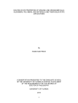
E-105
9/11/03
8:13 AM
Page 1
Bulletin E-105
Series 7116B Spirahelic® Pressure Indicating Transmitter
Specifications - Installation and Operating Instructions
(3) ø[5.57] MOUNTING
HOLES EQUALLY SPACED ON A
3-3/8 [85.73] BOLT CIRCLE
ZERO ADJUST
TERMINAL BLOCK
SPAN ADJUST
120°
ø5-7/8
[149.23]
3-7/64
[78.98]
DUAL PRESSURE
CONNECTION
1/2 MALE NPT
1/4 FEMALE NPT
Fig. A
The Dwyer 7116B Spirahelic® Pressure Indicating Transmitter
simultaneously provides local indication on a large, easily read analog scale while also converting that pressure into a standard two
wire, 4-20 mA signal for ranges from 0-60 to 0-600 psi. Positive
compatible gas pressure is measured to the accuracy of ±0.5% of
full scale. The gage employs a unique triple helix Bourdon tube for
precision measurement of compatible gases and liquids. The direct
drive design reduces friction and mass, resulting in exceptionally
good responsiveness, repeatability and accuracy. Because there are
no gears, springs linkages or other complicated mechanisms, wear
is practically eliminated. The electrical signal and conditioning is produced by a piezoresistive pressure cell. A 316 stainless steel connection block features convenient dual 1/4˝ female NPT and 1/2˝ male
NPT pressure connection. Pressure block also includes integral filter
plug to keep dirt out. Safety is assured with solid front case design
and rear blowout hole.
INSTALLATION
1. Select a location free from excessive vibration where the temperature limits of 20 to 120°F (-6.7 to 49°C) will not be exceeded. Mounting surface should be vertical to match the position in
which all standard gages are calibrated. Avoid locations in
direct sunlight which may cause accelerated discoloration of
the clear acrylic lens or where exposure to oil mist or other airborne vapors could likewise result in lens damage. Make sure
that the case relief area on the rear is not obstructed. This hole
is designed to direct pressure rear-ward in the event of a failure
of the Bourdon tube element. See complete safety recommendations at the end of this bulletin.
2. See Fig. A for mounting hole instructions.
DWYER INSTRUMENTS, INC.
P.O. BOX 373 • MICHIGAN CITY, INDIANA 46361, U.S.A.
SPECIFICATIONS
GAGE SPECIFICATIONS
Service: Compatible gases & liquids.
Wetted Materials: Inconel® X-750 Bourdon Tube, Type 316L SS
connection.
Housing: Black polycarbonate case and clear acrylic cover.
Accuracy: Grade 2A (0.5% F.S.).
Stability: ± 1% F.S./year.
Pressure Limit: 150% of full scale. Gage will maintain its specifications for overpressures up to 150% maximum range. Normal
operation should be between 25% and 75% of full scale.
Temperature Limits: 20 to 120°F (-6.67 to 48.9°C).
Size: 4-1/2˝ (114.3 mm) dial face. Design conforms to ASME
B40.1.
Process Connections: Dual size 1/4˝ male NPT / 1/4˝ female
NPT, bottom connection.
Weight: 29.5 oz (836.3 g).
TRANSMITTER SPECIFICATIONS
Accuracy: 0.5% F.S.
Temperature Limits: 20 to 120°F (-6.67 to 48.9°C).
Thermal Effect: ± 0.025% F.S./°F (0.045% F.S./°C).
Power Requirements: 10-35 VDC (2 wire).
Output Signal: 4-20 mA DC.
Zero & Span Adjustments: Externally accessible potentiometers.
Loop Resistance: DC, 0-1250 ohms.
Current Consumption: DC, 38 mA max.
Electrical Connections: Screw Terminals.
Mounting Orientation: Vertical.
Agency Approvals: CE.
Phone: 219/879-8000
Fax: 219/872-9057
www.dwyer-inst.com
e-mail: [email protected]
9/11/03
8:13 AM
Page 2
3. A 1/4˝ female NPT 1/2˝ male NPT pressure connection is furnished to allow you the choice of vertical (from below the
gage) or horizontal piping. The unused port is plugged. When
changing the pressure connection from the vertical to the horizontal position, use a minimal amount of thread sealant. Too
much could block the internal pressure passage. CAUTION:
When installing fittings or pipe always use a second wrench
on the 7/8˝ connection block. DO NOT allow torque to be
transmitted from the block to the case.
2-WIRE CONNECTION
7116B SERIES +
INDICATING
_
PRESSURE
TRANSMITTER
+
+
_
_
mA
POWER
SUPPLY
10-35 VDC
RECEIVER
ELECTRICAL CONNECTIONS
CAUTION: Do not exceed specified supply voltage ratings.
Permanent damage not covered by warranty will result.
This unit is not designed for 120 or 240 volt AC line operation.
Electrical connections to the Series 7116B Spirahelic® Pressure
Indicating Transmitter are made on the backside of the enclosure
unit. Feed stripped and tinned leads to the terminal block screws
marked 1 and 2. Refer to figure B for locations of the terminal
block, span and zero adjustments.
TERMINAL BLOCK
SPAN ADJUST
ZERO ADJUST
Fig. C
POWER SUPPLY VOLTAGE - VDC (2-WIRE CONNECTION)
RECEIVER RESISTANCE (OHMS)
E-105
1400
1300
1200
1100
1000
900
800
700
600
500
400
300
200
100
50
MAXIMUM VALUE (1250 OHMS)
OPERATING
REGION
0
5
10
15
20
25
30
35
40
Fig. D
Fig. B
Wire Length - The maximum length of wire connecting transmitter and receiver is a function of wire size and receiver resistance.
Wiring should not contribute to more than 10% of receiver resistance to total loop resistance. For extremely long runs (over 1000
feet), choose receivers with higher resistances to minimize size and
cost of connecting leads. When the wiring length is under 100 feet,
lead wire as small as 22 AWG can be used.
2-Wire Operation - An external power supply delivering 10-35
VDC with minimum current capability of 40 mA DC (per transmitter) must be used to power the control loop. See Fig. C for connection of the power supply, transmitter, and receiver. The range
of the appropriate receiver load resistance (RL) for the DC power
supply voltage available is expressed by the formula and graph in
Fig. D. Shielded two wire cable is recommended for control loop
wiring. If grounding is required use negative side of control loop
after receiver. See Fig. C.
Pneumatic Calibration Test
Use a dead weight tester or certified test gage having accuracy of
1/4% or better for ANSI Grade A gages, 0.1% or better for ANSI
Grade 2A gages. The test gage range should be comparable to
the range of the Series 7116B Spirahelic® Pressure Indicating
Transmitter gage being checked. Connect lines from the two
instruments to a tee and the third line from the tee to a controllable
source of pressure. Apply pressure slowly so that the pressure
equalizes throughout the system, compare readings. If the gage
being tested is found to need calibration return it to the address on
page 3.
E-105
9/11/03
8:13 AM
Page 3
Pressure Ranging
MAINTENANCE
Each standard Series 7116B Spirahelic® Pressure Indicating
Transmitter is factory calibrated to produce 4 mA at zero scale
reading and 20 mA at full scale reading. The following procedure
should be used if the pressure versus output signal relationship
needs to be checked.
No lubrication or periodic servicing is required after final installation
of the Series 7116B Spirahelic® Pressure Indicating Transmitter. A
periodic check of calibration is recommended following the procedure under pressure ranging and pneumatic calibration test.
Except for this, these transmitters are not field serviceable and
should be returned, freight prepaid, to the factory if repair is needed. Be sure to include a clear description of the problem plus any
application information available.
1. With the unit connected to the companion receiver per preceding instructions, insert an accurate milliammeter, with a full
scale reading of approximately 30 mA, in series with the current loop. A controllable pressure source capable of achieving
the desired range should be connected to the pressure port
of the transmitter and teed into an accurate reference pressure gage or manometer. The instrument must be ranged in
the same position in which it is going to be used. Vertical
mounting is recommended.
2. Apply electrical power to the system and allow it to stabilize
for 10 minutes.
Repairs
Field repair should not be attempted and may void warranty.
Gages needing calibration or other service should be returned prepaid to :
Dwyer Instruments, Inc.
ATTN: Repair Department
102 Indiana Highway 212
Michigan City, IN 46360
3. With no pressure applied to the transmitter, adjust “Zero”
adjustments so that loop current is 4 mA.
Multiple Receiver Installation
4. Apply full range pressure and adjust loop current to 20 mA
using “Span” adjustments.
5. Relieve pressure and allow transmitter to stabilize for 2 minutes.
6. Zero and Span adjustments may be interactive so repeat steps
3 thru 5 until zero and full range pressures consistently produce loop currents of 4 and 20 mA respectively.
7. Remove the milliammeter from the current loop and proceed
with final installation of the transmitter and receiver.
An advantage of the standard 4-20 mA DC output signal used in
Series 7116B Spirahelic® Pressure Indicating Transmitters is the
compatibility with a wide range of receivers. Devices such as the
A-701 Digital Readout, A-702 Digital Readout with alarms, an analog panel meter, a chart recorder and other process control equipment can be operated simultaneously. It is only necessary that all
devices be designed for a standard 4-20 mA input, the proper
polarity of input connections must be observed and the combined
receiver resistance's must not exceed the maximum for the current
loop. If the receiver indicates a negative or down scale reading, the
signal input leads are reversed.
E-105
9/11/03
8:13 AM
Page 4
The following material is excerpted from a standard titled
Gauges-Pressure Indicating Dial Type-Elastic Element
(AN-SI/ASME B40.1-1985) as published by The American
Society of Mechanical Engineers, 345 East 47th St., New
York, NY 10017. This information is furnished to assist the
user of Dwyer Spirahelic® gages in properly evaluating their
suitability for the intended application and conditions.
4 SAFETY
4.1 Scope
This Section of the Standard presents certain information to
guide users, suppliers, and manufacturers toward minimizing
the hazards that could result from misuse or misapplication of
pressure gauges with elastic elements. The user should
become familiar with all sections of this Standard, as all
aspects of safety cannot be covered in this Section. Consult
the manufacturer or supplier for advice whenever there is
uncertainty about the safe application of a pressure gauge.
4.2 General Discussion
4.2.1 Adequate safety results from intelligent planning and
careful selection and installation of gauges into a pressure system. The user should inform the supplier of all conditions pertinent to the application and environment so that the supplier
can recommend the most suitable gauge for the application.
4.2.2 The history of safety with respect to the use of pressure gauges has been excellent. Injury to personnel and damage to property have been minimal. In most instances, the
cause of failure has been misuse or misapplication.
4.2.3 The pressure sensing element in most gauges is subjected to high internal stresses, and applications exist where
the possibility of catastrophic failure is present. Pressure regulators, chemical (diaphragm) seals, pulsation dampers or
snubbers, syphons, and other similar items, are available for
use in these potentially hazardous systems. The hazard
potential increases at higher operating pressure.
4.2.4 The following systems are considered potentially hazardous and must be carefully evaluated:
(a) compressed gas systems
(b) oxygen systems
(c) systems containing hydrogen or free hydrogen atoms
(d) corrosive fluid systems (gas and liquid)
(e) pressure systems containing any explosive or flammable
mixture or medium
(f) steam systems
(g) non-steady pressure systems
(h) systems where high overpressure could be accidentally
applied
(i) systems wherein interchangeability of gauges could result
in hazardous internal contamination or where lower pressure
gauges could be installed in higher pressure systems
(j) systems containing radioactive or toxic fluids (liquids or
gases)
(k) systems installed in a hazardous environment
4.2.5 When gauges are to be used in contact with media
having known or uncertain corrosive effects or known to be
radioactive, random or unique destructive phenomena can
occur. In such cases the user should always furnish the supplier or manufacturer with information relative to the application and solicit his advice prior to installation of the gauge.
4.2.6 Fire and explosions within a pressure system can
cause pressure element failure with very violent effects, even
to the point of completely disintegrating or melting the pressure gauge. Violent effects are also produced when failure
occurs due to:
(a) hydrogen embrittlement
(b) contamination of a compressed gas
(c) formation of acetylides
(d) weakening of soft solder joints by steam or other heat
sources
(e) weakening of soft soldered or silver brazed joints caused
by heat sources such as fires
(f) corrosion
(g) fatigue
(h) mechanical shock
(i) excessive vibration
Failure in a compressed gas system can be expected to
produce violent effects.
4.2.7 Modes of Elastic Element Failure. There are four basic
modes of elastic element failure, as follows.
4.2.7.1 Fatigue Failure. Fatigue failure caused by pressure
induced stress generally occurs from the inside to the outside
along a highly stressed edge radius, appearing as a small
crack that propagates along the edge radius. Such failures
are usually more critical with compressed gas media than with
liquid media.
©Copyright 2003 Dwyer Instruments, Inc.
Fatigue cracks usually release the media fluid slowly so case
pressure buildup can be averted by providing pressure relief
openings in the gauge case. However, in high pressure elastic elements where the yield strength approaches the ultimate
strength of the element material, fatigue failure may resemble
explosive failure.
A restrictor placed in the gauge pressure inlet will reduce
pressure surges and restrict fluid flow into the partially open
Bourdon tube.
4.2.7.2. Overpressure Failure. Over pressure failure is
caused by the application of internal pressure greater than the
rated limits of the elastic element and can occur when a low
pressure gauge is installed in a high pressure port or system.
The effects of overpressure failure, usually more critical in
compressed gas systems than in liquid filled systems, are
unpredictable and may cause parts to be propelled in any
direction. Cases with pressure relief openings will not always
retain expelled parts.
Placing a restrictor in the pressure gauge inlet will not reduce
the immediate effect of failure, but will help control flow of
escaping fluid following rupture and reduce potential of secondary effects.
It is generally accepted that solid front cases with pressure
relief back will reduce the possibility of parts being projected
forward in the event of failure.
The window alone will not provide adequate protection
against internal case pressure buildup, and can be the most
hazardous component.
4.2.7.3 Corrosion Failure. Corrosion failure occurs when
the elastic element has been weakened through attack by corrosive chemicals present in either the media inside or the environment outside it. Failure may occur as pinhole leakage
through the elements walls or early fatigue failure due to stress
cracking brought about by chemical deterioration or embrittlement of the material.
A chemical (diaphragm) seal should be considered for use
with pressure media that may have a corrosive effect on the
elastic element.
4.2.7.4 Explosive Failure. Explosive failure is caused by the
release of explosive energy generated by a chemical reaction
such as can result with adiabatic compression of oxygen
occurs in the presence of hydrocarbons. It is generally
accepted that there is no known means of predicting the magnitude or effects of this type of failure. For this mode of failure,
a solid wall or partition between the elastic element and the
window will not necessarily prevent parts being projected forward.
4.2.8 Pressure Connection.
paragraph 3.3.4.
See recommendations in
4.3.4 In addition to the factors discussed above, the capability
of a pressure element is influenced by the design, materials, and
fabrication of the joints between its parts.
Common methods of joining are soft soldering, silver brazing,
and welding. Joints can be affected by temperature, stress,
and corrosive media. Where application questions arise, these
factors should be considered and discussed by the user and
manufacturer.
4.3.5 Some special applications require that the pressure element assembly have a high degree of leakage integrity. Special
arrangement should be made between manufacturer and user
to assure that the allowable leakage rate is not exceeded.
4.3.6 Cases
4.3.6.1 Cases, Solid Front. It is generally accepted that a
solid front case per paragraph 3.3.1 will reduce the possibility of
parts being projected forward in the event of elastic element
assembly failure. An exception is explosive failure of the elastic
element assembly.
4.3.6.2 Cases, Liquid Filled. It has been general practice
to use glycerine or silicone filling liquids. However, these fluids
may not be suitable for all applications. They should be avoided where strong oxidizing agents including, but not limited to,
oxygen, chlorine, nitric acid, and hydrogen peroxide are
involved. In the presence of oxidizing agents, potential hazard
can result from chemical reaction, ignition, or explosion.
Completely fluorinated or chlorinated fluids, or both, may be
more suitable for such applications.
The user shall furnish detailed information relative to the application of gauges having liquid filled cases and solicit the advice
of the gauge supplier prior to installation.
Consideration should also be given to the instantaneous
hydraulic effect that may be created by one of the modes of failure outlined in paragraph 4.2.7. The hydraulic effect due to
pressure element failure could cause the window to be projected forward even when a case having a solid front is employed.
4.3.7 Restrictor. Placing a restrictor between the pressure
connection and the elastic element will not reduce the immediate effect of failure, but will help control flow of escaping fluid following rupture and reduce the potential of secondary effects.
4.3.8 Specific Service Conditions
4.3.8.1 Specific applications for pressure gauges exist where
hazards are known. In many instances, requirements for
design, construction, and use of gauges for these applications
are specified by state or federal agencies or Underwriters
Laboratories, Inc. Some of these specific service gauges are
listed below. The list is not intended to include all types, and the
user should always advise the supplier of all application details.
4.3.8.2 Acetylene Gauges. A gauge designed to indicate
acetylene pressure. It shall be constructed using materials that
are compatible with commercially available acetylene.
4.3 Safety Recommendations.
4.3.1 Operating Pressure. The pressure gauge selected
should have a full scale pressure such that the operating pressure occurs in the middle half (25 to 75%) of the scale. The
full scale pressure of the gauge selected should be approximately two times the intended operating pressure.
Should it be necessary for the operating pressure to exceed
75% of full scale, contact the supplier for recommendations.
This does not apply to test, retarded, or suppressed scale
gauges.
4.3.2 Use of Gauges Near Zero Pressure. The use of
gauges near zero pressure is not recommended because the
accuracy, tolerance may be a large percentage of the applied
pressure. If, for example, a 0/100 psi Grade B gauge is used
to measure 6 psi , the accuracy of measurement will be ±3 psi,
or ±50% of the applied pressure. In addition, the scale of a
gauge is often laid out with takeup, which can result in further
inaccuracies when measuring pressures that are a small percentage of the gauge span.
For the same reasons, gauges should not be used for the
purpose of indicating that the pressure in a tank, autoclave, or
other similar unit has been completely exhausted to atmospheric pressure. Depending on the accuracy and the span of
the gauge and the possibility that takeup is incorporated at the
beginning of the scale, hazardous pressure may remain in the
tank even though the gauge is indicating zero pressure. A
venting device must be used to completely reduce the pressure before unlocking covers, removing fittings, or performing
other similar activities.
4.3.3 Compatibility With the Pressure Medium. The
elastic element is generally a thin walled member, which of
necessity operates under high stress conditions and must,
therefore, be carefully selected for compatibility with the pressure medium being measured. None of the common element
materials is impervious to every type of chemical attack. The
potential for corrosive attack is established by many factors,
including the concentration, temperature, and contamination
of the medium. The user should inform the gauge supplier of
the installation conditions so that the appropriate element
materials can be selected.
4.3.8.3 Ammonia Gauge. A gauge designed to indicate
ammonia pressure and to withstand the corrosive effects of
ammonia. The gauge may bear the inscription AMMONIA on
the dial. It may also include the equivalent saturation temperature scale markings on the dial.
4.3.8.4 Chemical Gauge. A gauge designed to indicate the
pressure of corrosive or high viscosity fluids, or both. The primary material(s) in contact with the pressure medium may be
identified on the dial. It may be equipped with a chemical
(diaphragm) seal, pulsation damper, or pressure relief device, or
a combination. These devices help to minimize potential damage to personnel and property in the event of gauge failure.
They may, however, also reduce accuracy or sensitivity, or both.
4.3.8.5 Oxygen Gauge. A gauge designed to indicate oxygen pressure. Cleanliness shall comply with Level IV (see
Section 5). The dial shall be clearly marked with a universal
symbol and/or USE NO OIL in red color (see paragraph
6.1.2.1).
4.4 Reuse of Pressure Gauges
It is not recommended that pressure gauges be moved from
one application to another. Should it be necessary, however,
the following must be considered.
4.4.1 Chemical Compatibility. The consequences of incompatibility can range from contamination to explosive failure. For
example, moving an oil service gauge to oxygen service can
result in explosive failure.
4.4.2 Partial Fatigue. The first installation may involve pressure pulsation that has expended most of the gauge life, resulting in early fatigue in the second installation.
4.4.3 Corrosion. Corrosion of the pressure element assembly in the first installation may be sufficient to cause early failure
in the second installation.
4.4.4 Other Considerations. When reusing a gauge, all
guidelines covered in this Standard relative to application of
gauges should be followed in the same manner as when a new
gauge is selected.
Printed in U.S.A. 9/03
DWYER INSTRUMENTS, INC.
P.O. BOX 373 • MICHIGAN CITY, INDIANA 46361, U.S.A.
Phone: 219/879-8000
Fax: 219/872-9057
FR# 17-443027-00 Rev. 2
www.dwyer-inst.com
e-mail: [email protected]