1
FDC-HKX
18. INVERTER DRIVEN MULTIINDOOR-UNIT CLIMATE
CONTROL SYSTEM
(OUTDOOR UNIT)
Alternative refrigerant R407C use models
FDCP140HKXE2, 224HKXE2, 280HKXE2
Refrigerant R22 use models
FDCJ140HKXE2, 224HKXE2, 280HKXE2
(INDOOR UNIT)
FDTJ28HKXE2, 36HKXE2, 45HKXE2, 56HKXE2
FDTJ71HKXE2, 90HKXE2, 112HKXE2, 140HKXE2
FDTWJ28HKXE2, 45HKXE2, 56HKXE2, 71HKXE2
FDTWJ90HKXE2, 112HKXE2, 140HKXE2
FDTSJ22HKXE2, 28HKXE2, 36HKXE2, 45HKXE2
FDTSJ71HKXE2
FDRJ22HKXE2, 28HKXE2, 45HKXE2, 56HKXE2
FDRJ71HKXE2, 90HKXE2, 112HKXE2, 140HKXE2
FDUMJ36HKXE2, 45HKXE2, 56HKXE2, 71HKXE2
FDUMJ90HKXE2, 112HKXE2, 140HKXE2
FDEJ36HKXE2, 45HKXE2, 56HKXE2, 71HKXE2
FDEJ112HKXE2, 140HKXE2
FDKJ22HKXE2, 28HKXE2, 36HKXE2, 45HKXE2
FDKJ56HKXE2, 71HKXE2
FDFLJ28HKXE2, 45HKXE2, 71HKXE2
691
FDC-HKX
CONTENTS
18.1 GENERAL INFORMATION ...................................................................... 693
18.1.1 Specific features ................................................................................ 693
18.1.2 How to read the model name............................................................ 695
18.1.3 Table of models ................................................................................. 695
18.1.4 Table of indoor units panel (Optional) ............................................. 695
18.2 SELECTION DATA ................................................................................... 696
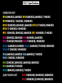
18.2.1 Specifications .................................................................................... 696
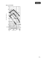
18.2.2 Range of usage & limitations ........................................................... 724
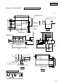
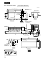
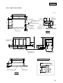
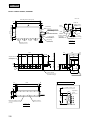
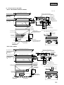
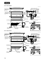
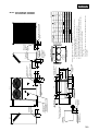
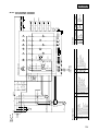
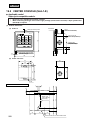
18.2.3 Exterior dimensions .......................................................................... 725
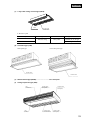
18.2.4 Exterior appearance .......................................................................... 750
18.2.5 Piping system .................................................................................... 753
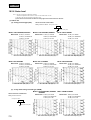
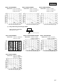
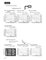
18.2.6 Selection chart ................................................................................... 755
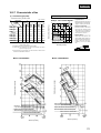
18.2.7 Characteristic of fan .......................................................................... 771
18.2.8 Noise level .......................................................................................... 776
18.3 ELECTRICAL DATA ................................................................................. 782
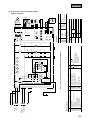
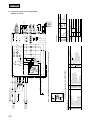
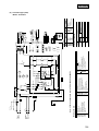
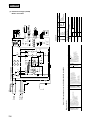
18.3.1 Electrical wiring ................................................................................. 782
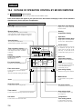
18.4 OUTLINE OF OPERATION CONTROL BY MICROCOMPUTER ............ 792
18.5 APPLICATION DATA ............................................................................... 808
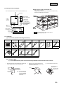
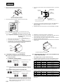
18.5.1 Installation of indoor unit ................................................................. 809
18.5.2 Installation of remote controller (Optional Parts)........................... 850
18.5.3 Installation of outdoor unit ............................................................... 852
18.5.4 Refrigerant piping.............................................................................. 856
18.5.5 Electric wiring .................................................................................... 864
18.5.6 Test run ............................................................................................... 873
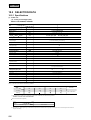
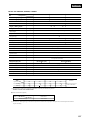
18.6 MAINTENANCE DATA ............................................................................. 874
692
FDC-HKX
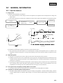
18.1 GENERAL INFORMATION
18.1.1 Specific features
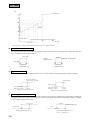
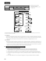
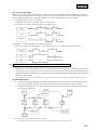
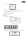
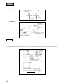
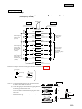
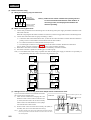
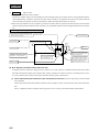
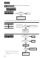
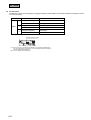
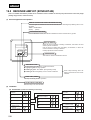
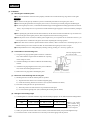
(1) Fuzzy control
(a) Response speed and stability are enhanced.
● The system automatically controls changes of return air temperature, set temperature and room temperature according to the
fuzzy control.
● The system response speed, can keep room temperature constant, and can adjust room temperature to set temperature quickly.
Inverter Hz
Set temp.
Temp. difference
Gradient of temp.
operation
FUZZY operation
E.E.V. pulse
Temp.
(Return air thermistor)
30
Heating
Room air
temp.II(ºC)
27
FUZZY
nal
Output valve
entio
20
Room air
temp.I(ºC)
Conv
: Fuzzy logic control
: Conventional control
: Set temp.
23
25
23
20
0
Input value
30
60
Time (min)
90
120
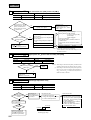
(b) Elimination of temperature irregularity as the time of operation ON/OF control
● The system finely controls the compressor to room temperature according to the temperature sensor, air conditions room
temperature consistently and improves cooling or heating feeling in each room(or minimize influence of shutdown in other
room).
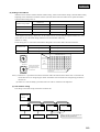
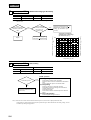
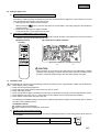
(2) Super lynk system
● Non polar 2-core signal wires for indoor, outdoor units by means of the automatic polarity selection.
● In addition, the max. 48 units can be controlled with a pair of signal wires. The high speed transmission method same as the
computer network system [start up of 48 units can be completed within a few seconds by the determination of operation mode
and the start of operation].
● As separate power supplies for the indoor and the outdoor units are employed, a pair of 2 signal wires only are required for the
inter connecting wiring of indoor and outdoor uniits regardless of the number of units so that the installation work can be
simplified, the cost of wiring work can be curtailed and causes of wiring error can be minimized.
(3) Floor layout can be changed by resetting address unit number.
● For change of floor layout, the control group can be recombined only by resetting address unit number.
(4) Installation of automatic address setting function
● The address setting method are divided into two types according to wiring method: “Automatic Address Setting,”“Remote
controller Address Setting” and “Manual Address Setting,” In case of the Automatic Address Setting, no address needs be set
as usual.
693
FDC-HKX
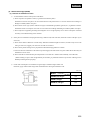
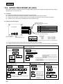
(5) Connectable indoor capacity
Capacity from 50% to 130% is possible.
● FDC140 type
Number of connectable units : 1 to 8 units
Connectable capacity : 7000 ~ 18200 W
● FDC224 type
Number of connectable units : 1 to 13 units
Connectable capacity : 11200 ~ 29200 W
● FDC280 type
Number of connectable units : 1 to 16 units
Connectable capacity : 14000 ~ 36400 W
(6) Cooling opetation down to -5˚C outdoor temperature
(7) Indoor units are available with 9 capacities, in 8 types and 47 models.
● 9 capacities…22(0.8 HP), 28(1 HP), 36(1.25 HP), 45(1.6 HP), 56(22 HP), 71(2.5 HP), 90(3.2 HP), 112(4 HP) and 140(5 HP).
● 8 types…Ceiling recessed type (FDT), 2-way outlet ceiling recessed type(FDTW), 1-way outlet ceiling recessed type(FDTS),
Cassetteria type(FDR), Satellite ducted type(FDUM), Ceiling suspension type(FDE), Wall mounted type(FDK) and Floor standing type(FDFL).
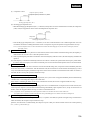
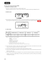
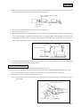
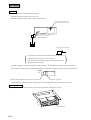
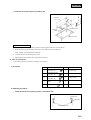
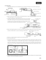
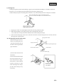
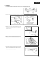
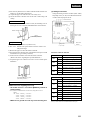
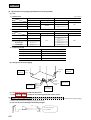
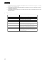
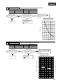
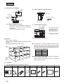
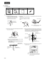
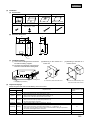
(8) Vertical blow or horizontal blow type can be selected for the outdoor unit.
horizontal blow
Standard
Vertical blow
Using an adapter
(Optional)
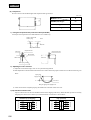
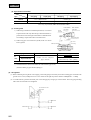
(9) Long piping design offeres One way piping length of 100 m
● Indoor and outdoor units can have a level difference of up to 50 m, with a one way piping length of up to 100 m. This is the top-class
long piping design in the industry. A level difference of as much as 15 m between indoor units ensures that the system can meet a
wide variety of air conditioning requirements in any building.
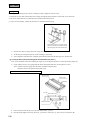
(10) Layout free refrigerant piping
The branch type piping makes the system flexible enough to satisfy any layout plan on the floor or in a room.
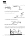
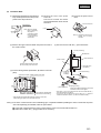
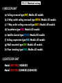
(11) Improvement of serviceability
(a) Failures of indoor unit and outdoor units are shown on the liquid crystal display on the remote controller.
● Failures of indoor unit and outdoor units can be checked by remote controller.
(b) Easy checking of outdoor inspection LED.
● The LED can be checked without removing the service panel, and faulty units can be easily indentified out of several units.
694
FDC-HKX
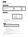
18.1.2 How to read the model name
Example:
FDC
P
224
H
KX
E
2
CE marking model
Application power source...See the specifications
Multi KX series
Heat pump type
Nominal capacity
P: R407C models
J: R22 models
Model name
Indoor unit
: FDT, FDTW, FDTS, FDR, FDUM
FDE, FDK, FDFL
Outdoor unit : FDC
18.1.3 Table of models
Capacity
Model
22
28
36
45
56
71
90
112
140
Ceiling recessed type
(FDT)
2-way outlet ceiling recessed type
(FDTW)
1-way outlet ceiling recessed type
(FDTS)
Cassetteria type
(FDR)
Stellite ducted type
(FDUM)
Ceiling suspension type
(FDE)
Wall mounted type
(FDK)
Floor standing type
(FDFL)
Outdoor units to
be combined
FDC
R407C
models
FDCP140HKXE2
(5 Horse Power)
FDCP224HKXE2
(8 Horse Power)
FDCP280HKXE2
(10 Horse Power)
R22 models
FDCJ140HKXE2
(5 Horse Power)
FDCJ224HKXE2
(8 Horse Power)
FDCJ280HKXE2
(10 Horse Power)
18.1.4 Table of indoor units panel (Optional)
Model
FDT
FDTW
(Standard type)
FDTW
(Attachment of ceiling material type)
FDTS
FDR
(Silent type)
FDR
(Canvas type)
Parts Model
Capacity:28,36,45,56,
71,90,112,140
Capacity:28,45,56
Capacity:71,80
Capacity:112,140
Capacity:28,45,56
Capacity:71,90
Capacity:112,140
Capacity:22,28,36,45
Capacity:71
Capacity:22,28,45,56
Capacity:71,90
Capacity:112,140
Capacity:22,28,45,56
Capacity:71,90
Capacity:112,140
T-PSA-32W-E
TW-PSA-28W-E
TW-PSA-38W-E
TW-PSA-48W-E
TW-PSB-28W-E
TW-PSB-38W-E
TW-PSB-48W-E
TS-PSA-26W-E
TS-PSA-36W-E
R-PNLS-26W-E
R-PNLS-36W-E
R-PNLS-46W-E
R-PNLC-26W-E
R-PNLC-36W-E
R-PNLC-46W-E
695
FDC-HKX
18.2 SELECTION DATA
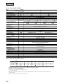
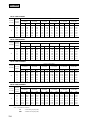
18.2.1 Specifications
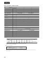
(1) Indoor unit
(a) Ceiling recessed type (FDT)
Models FDTJ28HKXE2, 36HKXE2
Models
FDTJ28HKXE2(3)
FDTJ36HKXE2(3)
W
2800
3600
W
3200
Item
1
Nominal cooling capacity*
Nominal heating capacity*2
4000
1 Phase 220/240V 50Hz
Power source
dB(A)
Noise level
Exterior dimensions
Height
Width
Depth
Net weight
Hi: 40 Me: 38 Lo: 34
mm
Unit:260
840
840
Panel:30
950
950
Unit:24 Panel:7
kg
Refrigerant equipment
Heat exchanger
Louver fine & inner grooved tubing
Refrigerant control
Electronic Expansion Valve +Capillary tube
Air handling equipment
Fan type & Q'ty
Turbo fan
Motor
W
1
17 1
Starting method
Line starting
Air flow(Standard)
Hi: 12 Me: 10 Lo: 9
CMM
Fresh air intake
Possible
Air filter, Q'ty
Long life filter
Shock & vibration absorber
1(Washable)
Rubber sleeve(for fan motor)
Insulation (noise & heat)
Polyurethane foam
Operation control
Operation switch
Remote control switch (Optional:RCD-HKX-S-E2)
Room temperature control
Thermostat by electronics
Internal thermostat for fan motor.
Frost protection thermostat
Safety equipment
Installation data
Refrigerant piping size
mm(in)
Liquid line: 6.35(1/4"), Gas line: 12.7(1/2")
Flare piping
Connecting method
Connectable with VP25
Drain hose
Necessary (both Liquid & Gas line)
Insulation for piping
Mounting kit
Accessories
Decorative Panel
Optional parts
FDCJ140HKXE2,224HKXE2,280HKXE2,FDCP140HKXE2,224HKXE2,280HKXE2
Outdoor units to be combined
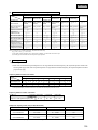
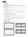
Notes (1) The data are measured at the following conditions.
Item
Indoor air temperature
Outdoor air temperature
DB
WB
DB
WB
Cooling*1
27
19
35
24
Heating*2
20
7
6
Operation
Standards
ISO-T1,JIS B8616
(2) This packaged air conditioner is manufactured and tested in conformity with the following standard.
JIS B8616"UNITARY AIR CONDITIONERS"
Decorative Panel model (Optional)
Item
Model
FDTJ28,36 type
Panel Part No.
T-PSA-32W-E
(3) The number "2", following the type of each model, represents"CE-marked model" especially for European Union, and for European nations which
require CE marking.
696
FDC-HKX
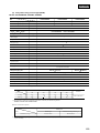
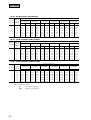
Models FDTJ45HKXE2, 56HKXE2, 71HKXE2
Models
Item
FDTJ45HKXE2(3)
FDTJ56HKXE2(3)
FDTJ71HKXE2(3)
Nominal cooling capacity*1
W
4500
5600
7100
Nominal heating capacity*2
W
5000
6300
8000
Power source
1 Phase 220/240V 50Hz
dB(A)
Noise level
Exterior dimensions
Height
Width
Depth
mm
Net weight
kg
Hi: 41 Me: 38 Lo: 36
Unit:260
Hi: 42 Me: 40 Lo: 39
840
840
Panel:30
950
950
Unit:24 Panel:7
Refrigerant equipment
Heat exchanger
Louver fine & inner grooved tubing
Refrigerant control
Electronic Expansion Valve +Capillary tube
Air handling equipment
Fan type & Q'ty
Turbo fan 1
W
20 1
CMM
Hi: 15 Me: 12 Lo: 10
Motor
25 1
Starting method
Line starting
Air flow(Standard)
Fresh air intake
Hi: 16 Me: 13 Lo: 11
Possible
Air filter, Q'ty
Long life filter
Shock & vibration absorber
1(Washable)
Rubber sleeve(for fan motor)
Insulation (noise & heat)
Polyurethane foam
Operation control
Operation switch
Remote control switch (Optional:RCD-HKX-S-E2)
Room temperature control
Thermostat by electronics
Internal thermostat for fan motor.
Frost protection thermostat
Safety equipment
Installation data
Refrigerant piping size
Liquid line: 6.35(1/4")
Gas line: 12.7(1/2")
mm(in)
Liquid line: 9.52(3/8")
Gas line: 15.88(5/8")
Flare piping
Connecting method
Connectable with VP25
Drain hose
Necessary (both Liquid & Gas lines)
Insulation for piping
Mounting kit
Accessories
Decorative Panel
Optional parts
FDCJ140HKXE2,224HKXE2,280HKXE2,FDCP140HKXE2,224HKXE2,280HKXE2
Outdoor units to be combined
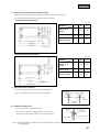
Notes (1) The data are measured at the following conditions.
Item
Indoor air temperature
Outdoor air temperature
DB
WB
DB
WB
Cooling*1
27
19
35
24
Heating*2
20
7
6
Operation
Standards
ISO-T1,JIS B8616
(2) This packaged air conditioner is manufactured and tested in conformity with the following standard.
JIS B8616"UNITARY AIR CONDITIONERS"
Decorative Panel model (Optional)
Item
Model
FDTJ45,56,71 type
Panel Part No.
T-PSA-32W-E
(3) The number "2", following the type of each model, represents"CE-marked model" especially for European Union, and for European nations which
require CE marking.
697
FDC-HKX
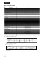
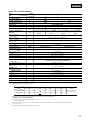
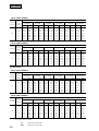
Models FDTJ90HKXE2, 112HKXE2, 140HKXE2
Models
Item
FDTJ90HKXE2(3)
FDTJ112HKXE2(3)
FDTJ140HKXE2(3)
Nominal cooling capacity*1
W
9000
11200
14000
Nominal heating capacity*2
W
10000
12500
16000
dB(A)
Hi: 44 Me: 42 Lo: 39
Power source
1 Phase 220/240V 50Hz
Noise level
Exterior dimensions
Height
Width
Depth
mm
Net weight
kg
Unit: 260
Panel:30
840
950
Hi: 52 Me:47 Lo: 42
840
950
Unit: 320
Panel:30
Unit:24 Panel:7
Hi: 54 Me: 48 Lo: 45
840
950
Unit:28 Panel:7
Refrigerant equipment
Heat exchanger
Louver fins & inner grooved tubing
Refrigerant control
Electronic Expansion Valve +Capillary tube
Air handling equipment
Fan type & Q'ty
840
950
Unit:30 Panel:7
Turbo fan 1
W
50 1
80 1
CMM
Hi: 21 Me: 15 Lo: 12
Hi: 28 Me: 24 Lo: 21
Motor
Starting method
130 1
Line starting
Air flow(Standard)
Fresh air intake
Hi: 30 Me: 26 Lo: 22
Possible
Air filter, Q'ty
Long life filter
Shock & vibration absorber
1(Washable)
Rubber sleeve(for fan motor)
Insulation (noise & heat)
Polyurethane foam
Operation control
Operation switch
Remote control switch (Optional:RCD-HKX-S-E2)
Room temperature control
Thermostat by electronics
Internal thermostat for fan motor.
Frost protection thermostat
Safety equipment
Installation data
Refrigerant piping size
Liquid line: 9.52(3/8")
Gas line: 15.88(5/8")
mm(in)
Liquid line: 9.52(3/8")
Gas line: 19.05(3/4")
Flare piping
Connecting method
Connectable with VP25
Drain hose
Necessary (both Liquid & Gas lines)
Insulation for piping
Mounting kit
Accessories
Decorative Panel
Optional parts
FDCJ140HKXE2,224HKXE2,280HKXE2,FDCP140HKXE2,224HKXE2,280HKXE2
Outdoor units to be combined
Notes (1) The data are measured at the following conditions.
Item
Indoor air temperature
Outdoor air temperature
DB
WB
DB
WB
Cooling*1
27
19
35
24
Heating*2
20
7
6
Operation
Standards
ISO-T1,JIS B8616
(2) This packaged air conditioner is manufactured and tested in conformity with the following standard.
JIS B8616"UNITARY AIR CONDITIONERS"
Decorative Panel model (Optional)
Item
Model
FDTJ90,112,140 type
Panel Part No.
T-PSA-32W-E
(3) The number "2", following the type of each model, represents"CE-marked model" especially for European Union, and for European nations which
require CE marking.
698
FDC-HKX
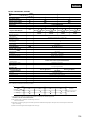
(b) 2-way outlet ceiling recessed type (FDTW)
Models FDTWJ28HKXE2, 45HKXE2, 56HKXE2
Models
Item
FDTWJ28HKXE2(3)
FDTWJ45HKXE2(3)
FDTWJ56HKXE2(3)
4500
5600
5000
6300
Nominal cooling capacity*1
W
2800
2
W
3200
Nominal heating capacity*
1 Phase 220/240V 50Hz
Power source
dB(A)
Noise level
Exterior dimensions
Height
Width
Depth
mm
Net weight
kg
Hi: 42 Me:38 Lo: 33
Unit:380 809 620
Panel:8
1055
680
Unit:31 Panel:10
Refrigerant equipment
Heat exchanger
Louver fins & inner grooved tubing
Refrigerant control
Electronic Expansion Valve +Capillary tube
Air handling equipment
Fan type & Q'ty
Centrifugal fan 2
Motor
55 1
W
Starting method
Line starting
Air flow(Standard)
CMM
Hi: 15 Me: 12 Lo: 9
Fresh air intake
Possible
Air filter, Q'ty
Long life filter
Shock & vibration absorber
2(Washable)
Rubber sleeve(for fan motor)
Insulation (noise & heat)
Polyurethane foam
Operation control
Operation switch
Remote control switch (Optional:RCD-HKX-S-E2)
Room temperature control
Thermostat by electronics
Internal thermostat for fan motor.
Frost protection thermostat
Safety equipment
Installation data
Refrigerant piping size
Liquid line: 6.35(1/4")
Gas line: 12.7(1/2")
mm(in)
Liquid line: 9.52(3/8")
Gas line: 15.88(5/8")
Flare piping
Connecting method
Connectable with VP25
Drain hose
Necessary (both Liquid & Gas lines)
Insulation for piping
Mounting kit
Accessories
Decorative Panel
Optional parts
FDCJ140HKXE2,224HKXE2,280HKXE2,FDCP140HKXE2,224HKXE2,280HKXE2
Outdoor units to be combined
Notes (1) The data are measured at the following conditions.
Item
Indoor air temperature
Outdoor air temperature
DB
WB
DB
WB
Cooling*1
27
19
35
24
Heating*2
20
7
6
Operation
Standards
ISO-T1,JIS B8616
(2) This packaged air conditioner is manufactured and tested in conformity with the following standard.
JIS B8616"UNITARY AIR CONDITIONERS"
Decorative Panel model (Optional)
Item
Model
FDTWJ28,45,56 type
Panel Part No.
Standard type
Attachment of ceiling material type
TW-PSA-28W-E
TW-PSB-28W-E
(3) The number "2", following the type of each model, represents"CE-marked model" especially for European Union, and for European nations which
require CE marking.
699
FDC-HKX
Models FDTWJ71HKXE2, 90HKXE2
Models
FDTWJ71HKXE2(3)
Item
FDTWJ90HKXE2(3)
Nominal cooling capacity*1
W
7100
9000
Nominal heating capacity*2
W
8000
10000
dB(A)
Hi: 42 Me: 39 Lo: 35
1 Phase 220/240V 50Hz
Power source
Noise level
Exterior dimensions
Height
Width
Depth
mm
Net weight
kg
Hi: 42 Me: 40 Lo: 36
Unit:380
1054
620
Panel:8
1300
680
Unit:37 Panel:11
Refrigerant equipment
Heat exchanger
Louver fins & inner grooved tubing
Refrigerant control
Electronic Expansion Valve +Capillay tube
Air handling equipment
Fan type & Q'ty
Centrifugal fan 2
W
55 1
CMM
Hi: 16 Me: 13 Lo: 11
Motor
80 1
Starting method
Line starting
Air flow(Standard)
Hi: 19 Me: 16 Lo: 12
Fresh air intake
Possible
Air filter, Q'ty
Long life filter
Shock & vibration absorber
2(Washable)
Rubber sleeve(for fan motor)
Insulation (noise & heat)
Polyurethane foam
Operation control
Operation switch
Remote control switch (Optional:RCD-HKX-S-E2)
Room temperature control
Thermostat by electronics
Internal thermostat for fan motor.
Frost protection thermostat
Safety equipment
Installation data
Refrigerant piping size
Liquid line: 9.52(3/8"),Gas line: 15.88(5/8")
mm(in)
Flare piping
Connecting method
Connectable with VP25
Drain hose
Necessary (both Liquid & Gas lines)
Insulation for piping
Mounting kit
Accessories
Decorative Panel
Optional parts
FDCJ140HKXE2,224HKXE2,280HKXE2,FDCP140HKXE2,224HKXE2,280HKXE2
Outdoor units to be combined
Notes (1) The data are measured at the following conditions.
Item
Indoor air temperature
Outdoor air temperature
DB
WB
DB
WB
Cooling*1
27
19
35
24
Heating*2
20
7
6
Operation
Standards
ISO-T1,JIS B8616
(2) This packaged air conditioner is manufactured and tested in conformity with the following standard.
JIS B8616"UNITARY AIR CONDITIONERS"
Decorative Panel model (Optional)
Item
Model
FDTWJ71,90 type
Panel Part No.
Standard type
Attachment of ceiling material type
TW-PSA-38W-E
TW-PSB-38W-E
(3) The number "2", following the type of each model, represents"CE-marked model" especially for European Union, and for European nations which
require CE marking.
700
FDC-HKX
Models FDTWJ112HKXE2, 140HKXE2
Models
Item
FDTWJ112HKXE2(3)
FDTWJ140HKXE2(3)
14000
Nominal cooling capacity*1
W
11200
Nominal heating capacity*2
W
12500
16000
Power source
1 Phase 220/240V 50Hz
dB(A)
Noise level
Exterior dimensions
Height
Width
Depth
mm
Net weight
kg
Hi: 44 Me: 41 Lo: 37
Hi: 46 Me: 43 Lo: 38
Unit:380
1524
620
Panel:8
1770
680
Unit:53 Panel:13
Refrigerant equipment
Heat exchanger
Louver fins & inner grooved tubing
Refrigerant control
Electronic Expansion Valve +Capillary tube
Air handling equipment
Fan type & Q'ty
Centrifugal fan 2
Motor
55
W
1,40
80
1
Starting method
1,45
1
Line starting
Air flow(Standard)
CMM
Hi: 28 Me: 24 Lo: 20
Hi: 30 Me: 26 Lo: 22
Fresh air intake
Possible
Air filter, Q'ty
Long life filter
Shock & vibration absorber
2(Washable)
Rubber sleeve(for fan motor)
Insulation (noise & heat)
Polyurethane foam
Operation control
Operation switch
Remote control switch (Optional:RCD-HKX-S-E2)
Room temperature control
Thermostat by electronics
Internal thermostat for fan motor.
Frost protection thermostat
Safety equipment
Installation data
Refrigerant piping size
Liquid line: 9.52(3/8"),Gas line: 19.05(3/4")
mm(in)
Flare piping
Connecting method
Connectable with VP25
Drain hose
Necessary (both Liquid & Gas linse)
Insulation for piping
Mounting kit
Accessories
Decorative Panel
Optional parts
FDCJ140HKXE2,224HKXE2,280HKXE2,FDCP140HKXE2,224HKXE2,280HKXE2
Outdoor units to be combined
Notes (1) The data are measured at the following conditions.
Item
Indoor air temperature
Outdoor air temperature
DB
WB
DB
WB
Cooling*1
27
19
35
24
Heating*2
20
7
6
Operation
Standards
ISO-T1,JIS B8616
(2) This packaged air conditioner is manufactured and tested in conformity with the following standard.
JIS B8616"UNITARY AIR CONDITIONERS"
Decorative Panel model (Optional)
Item
Model
FDTWJ112,140 type
Panel Part No.
Standard type
Attachment of ceiling material type
TW-PSA-48W-E
TW-PSB-48W-E
(3) The number "2", following the type of each model, represents"CE-marked model" especially for European Union, and for European nations which
require CE marking.
701
FDC-HKX
(c) 1-way outlet ceiling recessed type (FDTS)
Models FDTSJ22HKXE2, 28HKXE2, 36HKXE2
Model
Item
FDTSJ22HKXE2(3)
FDTSJ28HKXE2(3)
FDTSJ36HKXE2(3)
2800
3600
3200
4000
Nominal cooling capacity*1
W
2200
2
W
2500
Nominal heating capacity*
1 Phase 220/240V 50Hz
Power source
dB(A)
Noise level
Exterior dimensions
Height
Width
Depth
mm
Net weight
Kg
Hi: 40 Me: 39 Lo: 38
Hi: 39 Lo: 38
Unit:194
1040
650
Panel:10
1290
770
Unit:26 Panel:6
Refrigerant equipment
Heat exchanger
Louver fine & inner grooved tubing
Refrigerant control
Electronic Expansion Valve +Capillary tube
Air handling equipment
Fan type & Q'ty
Centrifugal fan 2
Motor
35
W
Starting method
1
Line starting
Air flow(Standard)
CMM
Hi: 11 Lo: 8
Hi: 12 Me: 11 Lo: 10
Fresh air intake
Possible
Air filter, Q'ty
Long life filter
Shock & vibration absorber
1(Washable)
Rubber sleeve(for fan motor)
Insulation (noise & heat)
Polyurethane foam
Operation control
Operation switch
Remote control switch (Optional:RCD-HKX-S-E2)
Room temperature control
Thermostat by electronics
Internal thermostat for fan motor.
Frost protection thermostat
Safety equipment
Installation data
Refrigerant piping size
Liquid line: 6.35(1/4"),Gas line: 12.7(1/2")
mm(in)
Flare piping
Connecting method
Connectable with VP25
Drain hose
Necessary (both Liquid & Gas lines)
Insulation for piping
Mounting kit
Accessories
Decorative Panel
Optional parts
FDCJ140HKXE2,224HKXE2,280HKXE2,FDCP140HKXE2,224HKXE2,280HKXE2
Outdoor units to be combined
Notes (1) The data are measured at the following conditions.
Item
Indoor air temperature
Outdoor air temperature
DB
WB
DB
WB
Cooling*1
27
19
35
24
Heating*2
20
7
6
Operation
Standards
ISO-T1,JIS B8616
(2) This packaged air conditioner is manufactured and tested in conformity with the following standard.
JIS B8616"UNITARY AIR CONDITIONERS"
Decorative Panel model (Optional)
Item
Model
FDTSJ22,28,36 type
Panel Part No.
With Auto Swing
TS-PSA-26W-E
(3) The number "2", following the type of each model, represents"CE-marked model" especially for European Union, and for Europern nations which
require CE marking.
702
FDC-HKX
Models FDTSJ45HKXE2, 71HKXE2
Model
Item
FDTSJ45HKXE2(3)
FDTSJ71HKXE2(3)
7100
Nominal cooling capacity*1
W
4500
Nominal heating capacity*2
W
5000
8000
Power source
1 Phase 220/240V 50Hz
Noise level
Hi: 43 Me: 40 Lo: 38
dB(A)
Exterior dimensions
Height
Width
Depth
mm
Net weight
kg
Unit:194
Panel:10
1040
1290
Hi: 44 Me: 40 Lo: 38
650
770
Unit:194
Panel:10
Unit:26 Panel:6
650
790
Unit:30 Panel:7
Refrigerant equipment
Heat exchanger
Louver fins & inner grooved tubing
Refrigerant control
Electronic Expansion Valve +Capillary tube
Air handling equipment
Fan type & Q'ty
1300
1500
Centrifugal fan 2
Centrifugal fan 4
W
40 1
25 2
CMM
Hi: 14 Me: 12 Lo: 10
Motor
Starting method
Line starting
Air flow(Standard)
Hi: 18 Me: 15 Lo: 12
Fresh air intake
Possible
Air filter, Q'ty
Long life filter
Shock & vibration absorber
1(Washable)
Rubber sleeve(for fan motor)
Insulation (noise & heat)
Polyurethane foam
Operation control
Operation switch
Remote control switch (Optional:RCD-HKX-S-E2)
Room temperature control
Thermostat by electronics
Internal thermostat for fan motor.
Frost protection thermostat
Safety equipment
Installation data
Refrigerant piping size
Liquid line: 6.35(1/4")
Gas line: 12.7(1/2")
mm(in)
Liquid line: 9.52(3/8")
Gas line: 15.88(5/8")
Flare piping
Connecting method
Connectable with VP25
Drain hose
Necessary (both Liquid & Gas lines)
Insulation for piping
Mounting kit
Accessories
Decorative Panel
Optional parts
Outdoor units to be combined
FDCJ140HKXE2, 224HKXE2, 280HKXE2,FDCP140HKE2,224HKXE2,280HKXE2
Notes (1) The data are measured at the following conditions.
Item
Indoor air temperature
Outdoor air temperature
DB
WB
DB
WB
Cooling*1
27
19
35
24
Heating*2
20
7
6
Operation
Standards
ISO-T1,JIS B8616
(2) This packaged air conditioner is manufactured and tested in conformity with the following standard.
JIS B8616"UNITARY AIR CONDITIONERS"
Decorative Panel model (Optional)
Item
Panel Part No.
With Auto Swing
Model
FDTSJ45 type
TS-PSA-26W-E
FDTSJ71 type
TS-PSA-36W-E
(3) The number "2", following the type of each model, represents"CE-marked model" especially for European Union, and for European nations which
require CE marking.
703
FDC-HKX
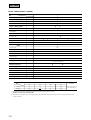
(d) Cassetteria type (FDR)
Models FDRJ22HKXE2, 28HKXE2
Models
FDRJ22HKXE2(4)
Item
Air inlet panel
Panel model (Option)
FDRJ28HKXE2(4)
Silent panel
Canvas panel
Silent panel
Canvas panel
R-PNLS-26W-E
R-PNLC-26W-E
R-PNLS-26W-E
R-PNLC-26W-E
Nominal cooling capacity*1
W
2200
2800
Nominal heating capacity*2
W
2500
3200
1 Phase 220/240V 50Hz
Power source
dB(A)
Hi: 41 Me: 39 Lo: 36
Hi: 42 Me: 40 Lo: 37
Hi: 42 Me: 40 Lo: 37
Hi: 43 Me: 41 Lo: 38
Exterior dimensions
Height
Width
Depth
mm
Unit:355 750 635
Panel:10 1040 750
Unit:355 750 635
Panel:10 864 585
Unit:355 750 635
Panel:10 1040 750
Unit:355 750 635
Panel:10 864 585
Net weight
kg
Unit:30
Panel:7
Unit:30
Panel:5
Unit:30
Panel:7
Unit:30
Panel:5
Noise level
Refrigerant equipment
Heat exchanger
Louver fins & inner grooved tubing
Refrigerant control
Electronic Expansion Valve +Capillary tube
Air handling equipment
Fan type & Q'ty
Centrifugal fan 2
Motor
40 1
W
50 1
Starting method
Line starting
Air flow(Standard)
Hi: 10 Me: 9 Lo: 8
CMM
Available static pressure
( at Me)
Hi: 12 Me: 11 Lo: 10
mmAq
Standard:4.5, Hi speed:8.5
Fresh air intake
Side or back
Air filter Q'ty
Long life filter
Shock & vibration absorber
1(Washable)
Rubber sleeve(for fan motor)
Insulation (noise & heat)
Polyurethane foam
Operation control
Operation switch
Remote control switch (Optional:RCD-HKX-E2)
Room temperature control
Thermostat by electronics
Internal thermostat for fan motor.
Frost protection thermostat
Safety equipment
Installation data
Refrigerant piping size
Liquid line: 6.35(1/4"),Gas line: 12.7(1/2")
mm(in)
Flare piping
Connecting method
Connectable with VP25
Drain hose
Necessary (both Liquid & Gas lines)
Insulation for piping
Mounting kit
Accessories
Silent panel, Canvas panel, Canvas duct
Optional parts
FDCJ140HKXE2,224HKXE2,280HKXE2,FDCP140HKE2,224HKXE2,280HKXE2
Outdoor units to be combined
Notes (1)The data are measured at the following conditions.
Item
Indoor air temperature
Outdoor air temperature
DB
WB
DB
WB
Cooling*1
27
19
35
24
2
20
7
6
Operation
Heating*
Standards
ISO-T1,JIS B8616
(2)This packaged air conditioner is manufactured and tested in conformity with the following standard.
JIS B8616"UNITARY AIR CONDITIONERS"
(3)Canvas panel is used in combination with following canvas duct
Canvas duct: HA01503
(4)The number "2",following the type of each model,represents"CE-marked model"especially for European Union, and for European nations which
require CE marking.
(5)Add the canvas duct lenght to the unit height for the canvas type.
704
FDC-HKX
Models FDRJ45HKXE2, 56HKXE2
Models
FDRJ45HKXE2(4)
Item
Air inlet panel
Silent panel
Panel model (Option)
R-PNLS-26W-E
Nominal cooling capacity*1
W
4500
Nominal heating capacity*2
W
5000
FDRJ56HKXE2(4)
Canvas panel
Silent panel
R-PNLC-26W-E
R-PNLS-26W-E
Canvas panel
R-PNLC-26W-E
5600
6300
Power source
1 Phase 220/240V 50Hz
dB(A)
Hi: 43 Me: 40 Lo: 37
Hi: 44 Me: 41 Lo: 38
Hi:43 Me: 40 Lo: 37
Hi: 44 Me: 41 Lo: 38
Exterior dimensions
Height
Width
Depth
mm
Unit:355 750 635
Panel:10 1040 750
Unit:355 750 635
Panel:10 864 585
Unit:355 750 635
Panel:10 1040 750
Unit:355 750 635
Panel:10 864 585
Net weight
kg
Unit:30
Panel:7
Unit:30
Panel:5
Unit:30
Panel:7
Unit:30
Panel:5
Noise level
Refrigerant equipment
Heat exchanger
Louver fins & inner grooved tubing
Refrigerant control
Electronic Expansion Valve +Capillary tube
Air handling equipment
Fan type & Q'ty
Centrifugal fan 2
Motor
W
55 1
CMM
Hi: 14 Me: 12 Lo: 11
mmAq
Standard:5.0, Hi speed:8.5
Starting method
Line starting
Air flow(Standard)
Available static pressure
( at Me)
Fresh air intake
Side or back
Air filter Q'ty
Long life filter
Shock & vibration absorber
1(Washable)
Rubber sleeve(for fan motor)
Insulation (noise & heat)
Polyurethane foam
Operation control
Operation switch
Remote control switch (Optional:RCD-HKX-E2)
Room temperature control
Thermostat by electronics
Internal thermostat for fan motor.
Frost protection thermostat
Safety equipment
Installation data
Refrigerant piping size
Liquid line: 9.52(3/8")
Gas line: 15.88(5/8")
Liquid line: 6.35(1/4")
Gas line: 12.7(1/2")
mm(in)
Flare piping
Connecting method
Connectable with VP25
Drain hose
Necessary (both Liquid & Gas lines)
Insulation for piping
Mounting kit
Accessories
Silent panel, Canvas panel, Canvas duct
Optional parts
FDCJ140HKXE2,224HKXE2,280HKXE2,FDCP140HKE2,224HKXE2,280HKXE2
Outdoor units to be combined
Notes (1)The data are measured at the following conditions.
Item
Indoor air temperature
Outdoor air temperature
DB
WB
DB
WB
Cooling*1
27
19
35
24
Heating*2
20
7
6
Operation
Standards
ISO-T1,JIS B8616
(2)This packaged air conditioner is manufactured and tested in conformity with the following standard.
JIS B8616"UNITARY AIR CONDITIONERS"
(3)Canvas panel is used in combination with following canvas duct
Canvas duct: HA01503
(4)The number "2",following the type of each model,represents"CE-marked model"especially for European Union, and for Europearn nations which
require CE marking.
(5)Add the canvas duct lenght to the unit height for the canvas type.
705
FDC-HKX
Models FDRJ71HKXE2, 90HKXE2
Models
FDRJ71HKXE2(4)
Item
Air inlet panel
Silent panel
Panel model (Option)
R-PNLS-36W-E
Nominal cooling capacity*1
W
7100
Nominal heating capacity*2
W
8000
FDRJ90HKXE2(4)
Canvas panel
Silent panel
R-PNLC-36W-E
R-PNLS-36W-E
Canvas panel
R-PNLC-36W-E
9000
10000
Power source
1 Phase 220/240V 50Hz
dB(A)
Hi: 43 Me: 40 Lo: 37
Hi: 44 Me: 41 Lo: 38
Hi: 44 Me: 40 Lo: 37
Hi: 44 Me: 41 Lo: 38
Exterior dimensions
Height
Width
Depth
mm
Unit:355 950 635
Panel:10 1240 750
Unit:355 950 635
Panel:10 1064 585
Unit:355 950 635
Panel:10 1240 750
Unit:355 950 635
Panel:10 1064 585
Net weight
kg
Unit:35
Panel:8
Unit:35
Panel:6
Unit:35
Panel:8
Unit:35
Panel:6
Noise level
Refrigerant equipment
Heat exchanger
Louver fins & inner grooved tubing
Refrigerant control
Electronic Expansion Valve +Capillary tube
Air handling equipment
Fan type & Q'ty
Centrifugal fan 2
Motor
W
100 1
90 1
Starting method
Line starting
Air flow(Standard)
Hi: 18 Me: 16 Lo: 14
CMM
Available static pressure
( at Me)
mmAp
Hi: 20 Me: 18 Lo: 15
Standard:4.5, Hi speed:8.0
Fresh air intake
Side or back
Air filter Q'ty
Long life filter
Shock & vibration absorber
1(Washable)
Rubber sleeve(for fan motor)
Insulation (noise & heat)
Polyurethane foam
Operation control
Operation switch
Remote control switch (Optional:RCD-HKX-E2)
Room temperature control
Thermostat by electronics
Internal thermostat for fan motor.
Frost protection thermostat
Safety equipment
Installation data
Refrigerant piping size
mm(in)
Liquid line: 9.52(3/8"),Gas line: 15.88(5/8")
Flare piping
Connecting method
Connectable with VP25
Drain hose
Necessary (both Liquid & Gas lines)
Insulation for piping
Mounting kit
Accessories
Silent panel, Canvas panel, Canvas duct
Optional parts
FDCJ140HKXE2,224HKXE2,280HKXE2,FDCP140HKE2,224HKXE2,280HKXE2
Outdoor units to be combined
Notes (1)The data are measured at the following conditions.
Item
Indoor air temperature
Outdoor air temperature
DB
WB
DB
WB
Cooling*1
27
19
35
24
Heating*2
20
7
6
Operation
Standards
ISO-T1,JIS B8616
(2)This packaged air conditioner is manufactured and tested in conformity with the following standard.
JIS B8616"UNITARY AIR CONDITIONERS"
(3)Canvas panel is used in combination with following canvas duct
Canvas duct: HA01490
(4)The number "2",following the type of each model,represents"CE-marked model"especially for European Union, and for European nations which
require CE marking.
(5)Add the canvas duct lenght to the unit height for the canvas type.
706
FDC-HKX
Models FDRJ112HKXE2, 140HKXE2
Models
FDRJ112HKXE2(4)
Item
Air inlet panel
Silent panel
Panel model (Option)
R-PNLS-46W-E
Nominal cooling capacity*1
W
11200
Nominal heating capacity*2
W
12500
FDRJ140HKXE2(4)
Canvas panel
Silent panel
R-PNLC-46W-E
R-PNLS-46W-E
Canvas panel
R-PNLC-46W-E
14000
16000
Power source
1 Phase 220/240V 50Hz
dB(A)
Hi: 45 Me: 42 Lo: 38
Hi: 46 Me: 43 Lo: 39
Hi: 46 Me: 43 Lo: 39
Hi: 47 Me: 44 Lo: 40
Exterior dimensions
Height
Width
Depth
mm
Unit:406 1370 635
Panel:10 1660 750
Unit:406 1370 635
Panel:10 1484 585
Unit:406 1370 635
Panel:10 1660 750
Unit:406 1370 635
Panel:10 1484 585
Net weight
kg
Unit:50
Panel:9
Unit:50
Panel:7
Unit:52
Panel:9
Unit:52
Panel:7
Noise level
Refrigerant equipment
Heat exchanger
Louver fins & inner grooved tubing
Refrigerant control
Electronic Expansion Valve +Capillary tube
Air handling equipment
Fan type & Q'ty
Centrifugal fan 3
Motor
W
45 1,
90 1
50 1,
Starting method
100 1
Line starting
Air flow(Standard)
Hi: 28 Me: 25 Lo: 22
CMM
Available static pressure
( at Me)
mmAq
Hi: 34 Me: 31 Lo: 27
Standard:5.0, Hi speed:8.0
Fresh air intake
Side or back
Air filter Q'ty
Long life filter
Shock & vibration absorber
2(Washable)
Rubber sleeve(for fan motor)
Insulation (noise & heat)
Polyurethane foam
Operation control
Operation switch
Remote control switch (Optional:RCD-HKX-E2)
Room temperature control
Thermostat by electronics
Internal thermostat for fan motor.
Frost protection thermostat
Safety equipment
Installation data
Refrigerant piping size
mm(in)
Liquid line: 9.52(3/8"),Gas line: 19.05(3/4")
Flare piping
Connecting method
Connectable with VP25
Drain hose
Necessary (both Liquid & Gas lines)
Insulation for piping
Mounting kit
Accessories
Silent panel, Canvas panel, Canvas duct
Optional parts
FDCJ140HKXE2,224HKXE2,280HKXE2,FDCP140HKE2,224HKXE2,280HKXE2
Outdoor units to be combined
Notes (1)The data are measured at the following conditions.
Item
Indoor air temperature
Outdoor air temperature
DB
WB
DB
WB
Cooling*1
27
19
35
24
Heating*2
20
7
6
Operation
Standards
ISO-T1,JIS B8616
(2)This packaged air conditioner is manufactured and tested in conformity with the following standard.
JIS B8616"UNITARY AIR CONDITIONERS"
(3)Canvas panel is used in combination with following canvas duct
Canvas duct: HA01484
(4)The number "2",following the type of each model,represents"CE-marked model"especially for European Union, and for European nations which
require CE marking.
(5)Add the canvas duct lenght to the unit height for the canvas type.
707
FDC-HKX
(e) Satellite ducted type (FDUM)
Models FDUMJ36HKXE2, 45HKXE2
Models
Item
FDUMJ36HKXE2(3)
FDUMJ45HKXE2(3)
4500
Nominal cooling capacity*1
W
3600
Nominal heating capacity*2
W
4000
5000
Power source
1 Phase 220/240V 50Hz
dB(A)
Noise level
Exterior dimensions
Height
Width
Depth
mm
Net weight
kg
Hi: 34 Me: 32 Lo: 29
Hi: 35 Me: 32 Lo: 29
299
750
635
34
Refrigerant equipment
Heat exchanger
Louver fins & inner grooved tubing
Refrigerant control
Electronic Expansion Valve +Capillary tube
Air handling equipment
Fan type & Q'ty
Centrifugal fan 2
W
50 1
CMM
Hi: 12 Me: 11 Lo: 10
Motor
55 1
Starting method
Line starting
Air flow(Standard)
Available static pressure
( at Me)
mmAq
Hi: 14 Me: 12 Lo: 11
Standard:5, Hi speed:8.5
Fresh air intake
Side
_
Air filter, Q'ty
Shock & vibration absorber
Rubber sleeve(for fan motor)
Insulation (noise & heat)
Polyurethane foam
Operation control
Operation switch
Remote control switch (Optional:RCD-HKX-E2)
Room temperature control
Thermostat by electronics
Internal thermostat for fan motor.
Frost protection thermostat
Safety equipment
Installation data
Refrigerant piping size
Liquid line: 6.35(1/4"),Gas line: 12.7(1/2")
mm(in)
Flare piping
Connecting method
Connectable with VP25
Drain hose
Necessary (both Liquid & Gas lines)
Insulation for piping
Mounting kit
_
Accessories
Optional parts
FDCJ140HKXE2,224HKXE2,280HKXE2,FDCP140HKE2,224HKXE2,280HKXE2
Outdoor units to be combined
Notes (1) The data are measured at the following conditions.
Item
Indoor air temperature
Outdoor air temperature
DB
WB
DB
WB
Cooling*1
27
19
35
24
2
20
7
6
Operation
Heating*
Standards
ISO-T1,JIS B8616
(2) This packaged air conditioner is manufactured and tested in conformity with the following standard.
JIS B8616"UNITARY AIR CONDITIONERS"
(3) The number "2", following the type of each model, represents"CE-marked model" especially for European Union, and for European nations which
require CE marking.
708
FDC-HKX
Models FDUMJ56HKXE2, 71HKXE2, 90HKXE2
Models
Item
FDUMJ56HKXE2(3)
FDUMJ71HKXE2(3)
FDUMJ90HKXE2(3)
Nominal cooling capacity*1
W
5600
7100
9000
Nominal heating capacity*2
W
6300
8000
10000
1 Phase 220/240V 50Hz
Power source
dB(A)
Noise level
Exterior dimensions
Height
Width
Depth
mm
Net weight
kg
Hi: 35 Me: 32 Lo: 29
299
750
Hi: 35 Me: 32 Lo: 29
635
299
34
Hi: 36 Me: 33 Lo: 30
950
635
40
Refrigerant equipment
Heat exchanger
Louver fins & inner grooved tubing
Refrigerant control
Electronic Expansion Valve +Capillary tube
Air handling equipment
Fan type & Q'ty
Centrifugal fan 2
Motor
W
55 1
90 1
Starting method
100 1
Line starting
Air flow(Standard)
CMM
Available static pressure
( at Me)
Hi: 14 Me: 12 Lo: 11
Hi: 18 Me: 16 Lo: 14
mmAq
Hi: 20 Me: 18 Lo: 15
Standard:5, Hi speed:8.5
Fresh air intake
Side
_
Air filter, Q'ty
Shock & vibration absorber
Rubber sleeve(for fan motor)
Insulation (noise & heat)
Polyurethane foam
Operation control
Operation switch
Remote control switch (Optional:RCD-HKX-E2)
Room temperature control
Thermostat by electronics
Internal thermostat for fan motor.
Frost protection thermostat
Safety equipment
Installation data
Refrigerant piping size
Liquid line: 9.52(3/8"),Gas line: 15.88(5/8")
mm(in)
Flare piping
Connecting method
Connectable with VP25
Drain hose
Necessary (both Liquid & Gas lines)
Insulation for piping
Mounting kit
_
Accessories
Optional parts
FDCJ140HKXE2,224HKXE2,280HKXE2,FDCP140HKE2,224HKXE2,280HKXE2
Outdoor units to be combined
Notes (1) The data are measured at the following conditions.
Item
Indoor air temperature
Outdoor air temperature
DB
WB
DB
WB
Cooling*1
27
19
35
24
Heating*2
20
7
6
Operation
Standards
ISO-T1,JIS B8616
(2) This packaged air conditioner is manufactured and tested in conformity with the following standard.
JIS B8616"UNITARY AIR CONDITIONERS"
(3) The number "2", following the type of each model, represents"CE-marked model" especially for European Union, and for European nations which
require CE marking.
709
FDC-HKX
Models FDUMJ112HKXE2, 140HKXE2
Models
Item
FDUMJ112HKXE2(3)
FDUMJ140HKXE2(3)
14000
Nominal cooling capacity*1
W
11200
Nominal heating capacity*2
W
12500
16000
1 Phase 220/240V 50Hz
Power source
dB(A)
Noise level
Exterior dimensions
Height
Width
Depth
mm
Net weight
kg
Hi: 38 Me: 35 Lo: 32
Hi: 39 Me: 37 Lo: 34
350
1370
635
57
59
Refrigerant equipment
Heat exchanger
Louver fins & inner grooved tubing
Refrigerant control
Electronic Expansion Valve +Capillary tube
Air handling equipment
Fan type & Q'ty
Centrifugal fan 3
Motor
W
45 1,
50 1, 100 1
90 1
Starting method
Line starting
Air flow(Standard)
Available static pressure
( at Me)
CMM
Hi: 28 Me: 25 Lo: 22
Hi: 34 Me: 31 Lo: 27
mmAq
Standard:6, Hi speed:9
Standard:6, Hi speed:8.5
Fresh air intake
Side
_
Air filter, Q'ty
Shock & vibration absorber
Rubber sleeve(for fan motor)
Insulation (noise & heat)
Polyurethane foam
Operation control
Operation switch
Remote control switch (Optional:RCD-HKX-E2)
Room temperature control
Thermostat by electronics
Internal thermostat for fan motor.
Frost protection thermostat
Safety equipment
Installation data
Refrigerant piping size
Liquid line: 9.52(3/8"),Gas line: 19.05(3/4")
mm(in)
Flare piping
Connecting method
Connectable with VP25
Drain hose
Necessary (both Liquid & Gas lines)
Insulation for piping
Mounting kit
_
Accessories
Optional parts
FDCJ140HKXE2,224HKXE2,280HKXE2,FDCP140HKE2,224HKXE2,280HKXE2
Outdoor units to be combined
Notes (1) The data are measured at the following conditions.
Item
Indoor air temperature
Outdoor air temperature
DB
WB
DB
WB
Cooling*1
27
19
35
24
2
20
7
6
Operation
Heating*
Standards
ISO-T1,JIS B8616
(2) This packaged air conditioner is manufactured and tested in conformity with the following standard.
JIS B8616"UNITARY AIR CONDITIONERS"
(3) The number "2", following the type of each model, represents"CE-marked model" especially for European Union, and for European nations which
require CE marking.
710
FDC-HKX
(f) Ceiling suspension type (FDE)
Models FDEJ36HKXE2, 45HKXE2
Models
FDEJ36HKXE2(3)
Item
FDEJ45HKXE2(3)
Nominal cooling capacity*1
W
3600
4500
Nominal heating capacity*2
W
4000
5000
Power source
1 Phase 220/240V 50Hz
Noise level
dB(A)
Exterior dimensions
Height
Width
Depth
mm
Net weight
kg
Hi: 43 Me:40 Lo: 38
184
1000
650 + 240
22
Refrigerant equipment
Heat exchanger
Louver fins & inner grooved tubing
Refrigerant control
Electronic Expansion Valve + Capillary tube
Air handling equipment
Fan type & Q'ty
Centrifugal fan 2
Motor
W
40 1
CMM
Hi: 14 Me: 12 Lo: 10
Starting method
Line starting
Air flow(Standard)
Fresh air intake
Not possible
Air filter, Q'ty
Polypropylene net
Shock & vibration absorber
2(Washable)
Rubber sleeve(for fan motor)
Insulation (noise & heat)
Polyurethane foam
Operation control
Operation switch
Remote control switch (Optional:RCD-HKX-S-E2)
Room temperature control
Thermostat by electronics
Internal thermostat for fan motor.
Frost protection thermostat
Safety equipment
Installation data
Refrigerant piping size
mm(in)
Liquid line: 6.35(1/4"), Gas line: 12.7(1/2")
Flare piping
Connecting method
Connectable with VP20
Drain hose
Necessary (both Liquid & Gas lines)
Insulation for piping
Mounting kit
_
Accessories
Optional parts
FDCJ140HKXE2,224HKXE2,280HKXE2,FDCP140HKE2,224HKXE2,280HKXE2
Outdoor units to be combined
Notes (1) The data are measured at the following conditions.
Item
Indoor air temperature
Outdoor air temperature
DB
WB
DB
WB
Cooling*1
27
19
35
24
2
20
7
6
Operation
Heating*
Standards
ISO-T1,JIS B8616
(2) This packaged air conditioner is manufactured and tested in conformity with the following standard.
JIS B8616"UNITARY AIR CONDITIONERS"
(3) The number "2", following the type of each model, represents"CE-marked model" especially for European Union, and for European nations which
require CE marking.
711
FDC-HKX
Models FDEJ56HKXE2, 71HKXE2
Models
Item
FDEJ56HKXE2(3)
FDEJ71HKXE2(3)
7100
Nominal cooling capacity*1
W
5600
Nominal heating capacity*2
W
6300
8000
Power source
1 Phase 220/240V 50Hz
dB(A)
Noise level
Exterior dimensions
Height
Width
Depth
mm
Net weight
kg
Hi: 44 Me:40 Lo: 38
Hi: 43 Me:40 Lo: 38
184
1000
650 + 240
184
22
Louver fins & inner grooved tubing
Refrigerant control
Electronic Expansion Valve + Capillary tube
Air handling equipment
Fan type & Q'ty
Centrifugal fan 4
Centrifugal fan 2
25 2
40 1
W
650 + 240
27
Refrigerant equipment
Heat exchanger
Motor
1260
Starting method
Line starting
Air flow(Standard)
CMM
Hi: 14 Me: 12 Lo: 10
Fresh air intake
Hi: 18 Me: 15 Lo: 12
Not possible
Air filter, Q'ty
Polypropylene net
Shock & vibration absorber
2(Washable)
Rubber sleeve(for fan motor)
Insulation (noise & heat)
Polyurethane foam
Operation control
Operation switch
Remote control switch (Optional:RCD-HKX-S-E2)
Room temperature control
Thermostat by electronics
Internal thermostat for fan motor.
Frost protection thermostat
Safety equipment
Installation data
Refrigerant piping size
mm(in)
Liquid line: 9.52(3/8"), Gas line: 15.88(5/8")
Flare piping
Connecting method
Connectable with VP20
Drain hose
Necessary (both Liquid & Gas lines)
Insulation for piping
Mounting kit
_
Accessories
Optional parts
FDCJ140HKXE2,224HKXE2,280HKXE2,FDCP140HKE2,224HKXE2,280HKXE2
Outdoor units to be combined
Notes (1) The data are measured at the following conditions.
Item
Indoor air temperature
Outdoor air temperature
DB
WB
DB
WB
Cooling*1
27
19
35
24
Heating*2
20
7
6
Operation
Standards
ISO-T1,JIS B8616
(2) This packaged air conditioner is manufactured and tested in conformity with the following standard.
JIS B8616"UNITARY AIR CONDITIONERS"
(3) The number "2", following the type of each model, represents"CE-marked model" especially for European Union, and for European nations which
require CE marking.
712
FDC-HKX
Models FDEJ112HKXE2, 140HKXE2
Models
Item
FDEJ112HKXE2(3)
FDEJ140HKXE2(3)
14000
Nominal cooling capacity*1
W
11200
Nominal heating capacity*2
W
12500
16000
Power source
1 Phase 220/240V 50Hz
dB(A)
Noise level
Exterior dimensions
Height
Width
Depth
mm
Net weight
kg
Hi: 50 Me:47 Lo: 42
Hi: 49 Me:46 Lo: 42
239
1260
650 + 240
239
34
Louver fins & inner grooved tubing
Refrigerant control
Electronic Expansion Valve +Capillary tube
Air handling equipment
Fan type & Q'ty
Centrifugal fan 4
Centrifugal fan 3
35 1 + 55 1
W
650 + 240
40
Refrigerant equipment
Heat exchanger
Motor
1470
55 2
Starting method
Line starting
Air flow(Standard)
CMM
Hi: 28 Me: 25 Lo: 22
Fresh air intake
Hi: 34 Me: 30 Lo: 26
Not possible
Polypropylene net
Air filter, Q'ty
Shock & vibration absorber
2(Washable)
Rubber sleeve(for fan motor)
Insulation (noise & heat)
Polyurethane foam
Operation control
Operation switch
Remote control switch (Optional:RCD-HKX-S-E2)
Room temperature control
Thermostat by electronics
Internal thermostat for fan motor.
Frost protection thermostat
Safety equipment
Installation data
Refrigerant piping size
mm(in)
Liquid line: 9.52(3/8"), Gas line: 19.05(3/4")
Flare piping
Connecting method
Connectable with VP20
Drain hose
Necessary (both Liquid & Gas lines)
Insulation for piping
Mounting kit
_
Accessories
Optional parts
FDCJ140HKXE2,224HKXE2,280HKXE2,FDCP140HKE2,224HKXE2,280HKXE2
Outdoor units to be combined
Notes (1) The data are measured at the following conditions.
Item
Indoor air temperature
Outdoor air temperature
DB
WB
DB
WB
Cooling*1
27
19
35
24
2
20
7
6
Operation
Heating*
Standards
ISO-T1,JIS B8616
(2) This packaged air conditioner is manufactured and tested in conformity with the following standard.
JIS B8616"UNITARY AIR CONDITIONERS"
(3) The number "2", following the type of each model, represents"CE-marked model" especially for European Union, and for European nations which
require CE marking.
713
FDC-HKX
(g) Wall mounted type (FDK)
Models FDKJ22HKXE2, 28HKXE2, 36HKXE2, 45HKXE2
Models
Item
FDKJ22HKXE2(3)
FDKJ28HKXE2(3)
FDKJ36HKXE2(3)
FDKJ45HKXE2(3)
Nominal cooling capacity*1
W
2200
2800
3600
4500
Nominal heating capacity*2
W
2500
3200
4000
5000
dB(A)
Hi: 42 Lo: 37
Power source
1 Phase 220/240V 50Hz
Noise level
Exterior dimensions
Height
Width
Depth
mm
Net weight
kg
Hi: 42 Me:40 Lo: 37
375
930
Hi: 44 Me:41 Lo: 37
194
19
Refrigerant equipment
Heat exchanger
Louver fins & inner grooved tubing
Refrigerant control
Electronic Expansion Valve + Capillary tube
Air handling equipment
Fan type & Q'ty
Centrifugal fan 2
Motor
W
30 1
35 1
Starting method
Line starting
Air flow(Standard)
CMM
Hi: 9 Lo: 8
Hi: 10 Me: 9 Lo: 8
Fresh air intake
Hi: 11.5 Me: 10 Lo: 8
Not possible
Air filter, Q'ty
Polypropylene net
Shock & vibration absorber
2(Washable)
Rubber sleeve(for fan motor)
Insulation (noise & heat)
Polyurethane foam
Operation control
Operation switch
Remote control switch (Optional:RCD-HKX-S-E2)
Room temperature control
Thermostat by electronics
Internal thermostat for fan motor.
Frost protection thermostat
Safety equipment
Installation data
Refrigerant piping size
mm(in)
Liquid line: 6.35(1/4"), Gas line: 12.7(1/2")
Flare piping
Connecting method
Connectable with I.D. 16mm
Drain hose
Necessary (both Liquid & Gas lines)
Insulation for piping
Mounting kit
Accessories
Optional parts
—
FDCJ140HKXE2,224HKXE2,280HKXE2,FDCP140HKE2,224HKXE2,280HKXE2
Outdoor units to be combined
Notes (1) The data are measured at the following conditions.
Item
Indoor air temperature
Outdoor air temperature
DB
WB
DB
WB
Cooling*1
27
19
35
24
2
20
7
6
Operation
Heating*
Standards
ISO-T1,JIS B8616
(2) This packaged air conditioner is manufactured and tested in conformity with the following standard.
JIS B8616"UNITARY AIR CONDITIONERS"
(3) The number "2", following the type of each model, represents"CE-marked model" especially for European Union, and for European nations which
require CE marking.
714
FDC-HKX
Models FDKJ56HKXE2, 71HKXE2
Model
Item
FDKJ56HKXE2(3)
FDKJ71HKXE2(3)
7100
Nominal cooling capacity*1
W
5600
Nominal heating capacity*2
W
6300
8000
Power source
1 Phase 220/240V 50Hz
dB(A)
Noise level
Exterior dimensions
Height
Width
Depth
mm
Net weight
kg
Hi: 46 Me:43 Lo: 39
375 1148
Hi: 47 Me:44 Lo: 40
194
375
20
Louver fins & inner grooved tubing
Refrigerant control
Electronic Expansion Valve + Capillary tube
Air handling equipment
Fan type & Q'ty
Tangential fan 1
W
194
22
Refrigerant equipment
Heat exchanger
Motor
1436
Tangential fan 2
40 1
45 1
Starting method
Line starting
Air flow(Standard)
CMM
Hi: 17 Me: 15 Lo: 13
Fresh air intake
Hi: 21 Me: 18 Lo: 15
Not possible
Air filter, Q'ty
Polypropylene net
Shock & vibration absorber
2(Washable)
Rubber sleeve(for fan motor)
Insulation (noise & heat)
Polyurethane foam
Operation control
Operation switch
Remote control switch (Optional:RCD-HKX-S-E2)
Room temperature control
Thermostat by electronics
Internal thermostat for fan motor.
Frost protection thermostat
Safety equipment
Installation data
Refrigerant piping size
mm(in)
Liquid line: 9.52(3/8"), Gas line: 15.88(5/8")
Flare piping
Connecting method
Connectable with I.D. 16mm
Drain hose
Necessary (both Liquid & Gas lines)
Insulation for piping
Mounting kit
_
Accessories
Optional parts
FDCJ140HKXE2,224HKXE2,280HKXE2,FDCP140HKE2,224HKXE2,280HKXE2
Outdoor units to be combined
Notes (1) The data are measured at the following conditions.
Item
Indoor air temperature
Outdoor air temperature
DB
WB
DB
WB
Cooling*1
27
19
35
24
Heating*2
20
7
6
Operation
Standards
ISO-T1,JIS B8616
(2) This packaged air conditioner is manufactured and tested in conformity with the following standard.
JIS B8616"UNITARY AIR CONDITIONERS"
(3) The number "2", following the type of each model, represents"CE-marked model" especially for European Union, and for European nations which
require CE marking.
715
FDC-HKX
(h) Floor standing type (FDFL)
Models FDFLJ28HKXE2, 45HKXE2, 71HKXE2
Model
Item
FDFLJ28HKXE2(3)
FDFLJ45HKXE2(3)
FDFLJ71HKXE2(3)
Nominal cooling capacity*1
W
2800
4500
7100
Nominal heating capacity*2
W
3200
5000
8000
dB(A)
Hi: 41 Me:38 Lo: 36
1 Phase 220/240V 50Hz
Power source
Noise level
Exterior dimensions
Height
Width
Depth
Net weight
mm
630
kg
Hi: 43 Me:41 Lo: 40
1196
630
225
1481
40
32
Refrigerant equipment
Heat exchanger
Louver fins & inner grooved tubing
Refrigerant control
Electronic Expansion Valve + Capillary tube
Air handling equipment
Fan type & Q'ty
Centrifugal fan 2
Motor
W
30 1
40 1
Starting method
Line starting
Air flow(Standard)
CMM
Hi: 12 Me: 11 Lo: 10
Hi: 14 Me: 12 Lo: 10
Fresh air intake
Hi: 18 Me: 15 Lo: 12
Not possible
Air filter, Q'ty
Polypropylene net
Shock & vibration absorber
2(Washable)
Rubber sleeve(for fan motor)
Insulation (noise & heat)
Polyurethane foam
Operation control
Operation switch
Remote control switch (Optional:RCD-HKXFL-E2)
Room temperature control
Thermostat by electronics
Internal thermostat for fan motor.
Frost protection thermostat
Safety equipment
Installation data
Refrigerant piping size
mm(in)
Liquid line: 6.35(1/4"), Gas line: 12.7(1/2")
Liquid line: 9.52(3/8")
Gas line: 15.88(5/8")
Flare piping
Connecting method
Connectable with VP20
Drain hose
Necessary (both Liquid & Gas lines)
Insulation for piping
Mounting kit
_
Accessories
Optional parts
FDCJ140HKXE2,224HKXE2,280HKXE2,FDCP140HKE2,224HKXE2,280HKXE2
Outdoor units to be combined
Notes (1) The data are measured at the following conditions.
Item
Indoor air temperature
Outdoor air temperature
DB
WB
DB
WB
Cooling*1
27
19
35
24
Heating*2
20
7
6
Operation
Standards
ISO-T1,JIS B8616
(2) This packaged air conditioner is manufactured and tested in conformity with the following standard.
JIS B8616"UNITARY AIR CONDITIONERS"
(3) The number "2", following the type of each model, represents"CE-marked model" especially for European Union, and for European nations which
require CE marking.
716
225
FDC-HKX
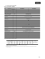
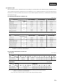
(2) Outdoor unit
(a) Alternative refrigerant R407C use models
Models FDCP140HKXE2, 224HKXE2, 280HKXE2
Models
FDCP140HKXE2(3)
Item
FDCP224HKXE2(3)
FDCP280HKXE2(3)
3 Phase 380/415V 50Hz
Power source
Nominal cooling capacity*1
W
14000
22400
28000
Nominal heating capacity*2
W
16000
25000
31500
dB(A)
56
58
59
Noise level
Exterior dimensions
Height
Width
Depth
Net weight
mm
1450
600
1450
150
kg
Refrigerant equipment
compressor type & Q' ty
Motor
690
GT5539HAS01
1
600
250
265
GT5539HAS02 1
GTA5539HLS42 1
GT5539HAS02 1
GUA5570HLS42 1
3.5
3.5
kW
1350
Starting method
1, 2.2
1
3.5
1, 3.75
1
Direct start
Capacity control
%
100 ~ 25
Crankcase heater
W
33
100 ~ 16
33
100 ~ 12
2
33
1, 40
1
Louver fines & inner grooved tubing
Heat exchanger
Refrigerant control
Expansion Valve +Capillary tube
Refrigerant
R407C
Quantity
kg
9
Refrigerant oil
12
1.45 (MA32)
2.9 (MA32)
Defrost control
3.05 (MA32)
MC controlled De-Icer
Air handling equipment
Fan type & Q'ty
Motor
Centrifugal fan
1
Centrifugal fan
100 1
W
2
100 2
Starting method
Direct start
Air flow(Standard)
CMM
90
180
Shock & vibration absorber
Rubber mount (for compressor)
Compressor overheat protection, overeurrent protection, power transformer overheating
protection, abnormal high pressure protection
Safety equipment
Installation data
Refrigerant piping size
Liquid line: 9.52(3/8")
Gas line: 19.05(3/4")
mm(in)
Liquid line: 12.7(1/2")
Gas line: 25.4(1")
Connecting method
Liquid line: 12.7(1/2")
Gas line: 28.58(11/8")
Brazing
Drain
Hole for drain( 20
4pcs)
Insulation for piping
Hole for drain( 20
8pcs,
50
1pcs)
Necessary (both Liquid & Gas lines)
_
Accessories
Indoor units to be combined
FDTJ28, 36, 45, 56, 71, 90, 112, 140type
FDTWJ28, 45, 56, 71, 90, 112, 140type
FDTSJ22, 28, 36, 45, 71type
FDRJ22, 28, 45, 56, 71, 90, 112, 140type
FDUMJ36, 45, 56, 71, 90, 112, 140type
FDEJ36, 45, 56, 71, 112, 140type
FDKJ22, 28, 36, 45, 56, 71type
FDFLJ28, 45, 71type
Notes (1) The cooling and heating capabilities imply the values when the indoor unit of rated capacity is connected under the condition specified in JIS-B8616.
(2) The refrigerant quantity in the connecting pipe is not included Charge it additionally at the site.
(3) The number "2", following the type of each model, represents"CE-marked model" especially for European Union, and for European nations which
require CE marking.
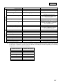
Refrigerant distributor pipe set Number list (Optional)
Outdoor unit
Number of combined indoor units
FDCP140HKXE2
1~8
FDCP224HKXE2
1~13(2)
FDCP280HKXE2
(2)
1~16
Flow divider pipe(1) (Total capacity after the flow division)
Downstream capacity 101 or less
: DIS-1KX10-E
Downstream capacity 101 or more : DIS-1KX30-E
Notes (1) The flow divider pipe that should be used depends on the indoor unit total downstream capacity. (1 set is required for each flow division.)
(2) When there are 13 or more indoor units there are limits on the length of the piping after the flow division, so refer to the usage range.
717
FDC-HKX
(b) Refrigerant R22 use models
Models FDCJ140HKXE2, 224HKXE2, 280HKXE2
Models
FDCJ140HKXE2(3)
Item
FDCJ224HKXE2(3)
FDCJ280HKXE2(3)
3 Phase 380/415V 50Hz
Power source
Nominal cooling capacity*1
W
14000
22400
28000
Nominal heating capacity*2
W
16000
25000
31500
dB(A)
56
58
59
Noise level
Exterior dimensions
Height
Width
Depth
Net weight
mm
1450
1450
600
150
kg
Refrigerant equipment
compressor type & Q' ty
Motor
690
GT5539EAS01
600
250
265
GT5539EAS02
GTA5539ES42
1
3.5
3.5
kW
1350
Starting method
1, 2.2
1
1
GT5539EAS02
GUA5570ES42
1
3.5
1, 3.75
1
Direct start
Capacity control
%
100 ~ 25
Crankcase heater
W
33
100 ~ 16
33
100 ~ 12
2
33
1, 40
1
Louver fines & inner grooved tubing
Heat exchanger
Refrigerant control
Expansion Valve +Capillary tube
Refrigerant
R22
Quantity
kg
Refrigerant oil
9
12
1.45 (BARREL FREEZE 32SAM) 2.9 (BARREL FREEZE 32SAM) 3.05 (BARREL FREEZE 32SAM)
Defrost control
MC controlled De-Icer
Air handling equipment
Fan type & Q'ty
Motor
Centrifugal fan
1
Centrifugal fan
100 1
W
2
100 2
Starting method
Direct start
Air flow(Standard)
CMM
90
180
Shock & vibration absorber
Rubber mount (for compressor)
Compressor overheat protection, overeurrent protection, power transformer overheating
protection, abnormal high pressure protection
Safety equipment
Installation data
Refrigerant piping size
Liquid line: 9.52(3/8")
Gas line: 19.05(3/4")
mm(in)
Liquid line: 12.7(1/2")
Gas line: 25.4(1")
Connecting method
Liquid line: 12.7(1/2")
Gas line: 28.58(11/8")
Brazing
Drain
Hole for drain( 20
4pcs)
Insulation for piping
Hole for drain( 20
8pcs,
50
1pcs)
Necessary (both Liquid & Gas lines)
_
Accessories
Indoor units to be combined
FDTJ28, 36, 45, 56, 71, 90, 112, 140type
FDTWJ28, 45, 56, 71, 90, 112, 140type
FDTSJ22, 28, 36, 45, 71type
FDRJ22, 28, 45, 56, 71, 90, 112, 140type
FDUMJ36, 45, 56, 71, 90, 112, 140type
FDEJ36, 45, 56, 71, 112, 140type
FDKJ22, 28, 36, 45, 56, 71type
FDFLJ28, 45, 71type
Notes (1) The cooling and heating capabilities imply the values when the indoor unit of rated capacity is connected under the condition specified in JIS-B8616.
(2) The refrigerant quantity in the connecting pipe is not included Charge it additionally at the site.
(3) The number "2", following the type of each model, represents"CE-marked model" especially for European Union, and for European nations which
require CE marking.
Refrigerant distributor pipe set Number list (Optional)
Outdoor unit
Number of combined indoor units
FDCJ140HKXE2
1~8
FDCJ224HKXE2
1~13(2)
FDCJ280HKXE2
(2)
1~16
Flow divider pipe(1) (Total capacity after the flow division)
Downstream capacity 101 or less
: DIS - 1KX10 - E
Downstream capacity 101 or more : DIS - 1KX30 - E
Notes (1) The flow divider pipe that should be used depends on the indoor unit total downstream capacity. (1 set is required for each flow division.)
(2) When there are 13 or more indoor units there are limits on the length of the piping after the flow division, so refer to the usage range.
718
1
1
FDC-HKX
(3) Operation chart
Since the Multi KX series air conditioner units are free multitype to which the indoor units of different capacity and different model
can be combined, the operation characteristics of all combinations are very complicated, therefore only the individual operation
characteristics of indoor and outdoor units are shown. For the combined operation characteristics, calculate them with the method
shown in the next page.
(a) Operating characteristic of outdoor unit
(380 V/415 V)
Models
Item
Cooling input
kW
Heating input
Cooling running current
A
Heating running current
Inrush current (MAX.)
FDCJ140HKXE(2)
FDCJ224HKXE(2)
FDCJ280HKXE(2)
6.8/6.8
9.8/9.8
11.7/11.7
5.7/5.9
8.3/8.4
9.4/9.5
10.7/10.2
15.7/14.6
19.3/19.0
8.8/8.4
13.0/12.0
15.7/15.7
5
48
70
97/93
95/93
92/86
98/98
97/97
91/84
A
Cooling power factor
%
Heating power factor
(380 V/415 V)
Models
Item
Cooling input
kW
Heating input
Cooling running current
A
Heating running current
Inrush current (MAX.)
FDCP140HKXE2
FDCP224HKXE2
FDCP280HKXE2
6.8/6.8
9.8/9.8
11.7/11.7
6.0/6.1
9.3/9.4
10.4/10.4
10.7/10.2
15.7/14.6
19.3/19.0
9.3/8.6
14.7/14.0
16.5/16.5
A
Cooling power factor
%
Heating power factor
5
48
70
97/93
95/93
92/86
98/99
96/93
96/88
Note (1) This packaged air conditioner is manufactured and tested in conformity with the following standard.
JIS B8616 “UNITARY AIR CONDITIONERS”
(b) Operating characteristic of indoor unit
FDT Series
(220 V/240 V)
Models
Item
FDT Series
71
90
112
140
Power input (kW)
28
0.09/0.10
36
45
0.10/0.12
56
0.10/0.12
0.11/0.13
0.17/0.20
0.21/0.24
Running current (A)
0.40/0.44
0.45/0.49
0.47/0.50
0.50/0.55
0.75/0.81
0.93/1.02
FDTW Series
(220 V/240 V)
Models
Item
Power input (kW)
Running current (A)
FDTW Series
28
45
56
71
90
112
140
0.09/0.10
0.10/0.11
0.13/0.16
0.20/0.24
0.23/0.27
0.41/0.42
0.40/0.44
0.60/0.65
0.90/0.98
1.03/1.13
Notes (1) This packaged air conditioner is manufactured and tested in conformity with the following standard.
JIS B8616 “UNITARY AIR CONDITIONERS”
(2) The values shown in the above table are common to both cooling and heating operations.
719
FDC-HKX
FDTS Series
(220 V/240 V)
Models
FDTS Series
45
71
Power input (kW)
0.07/0.08
0.10/0.11
0.12/0.15
Running current (A)
0.33/0.36
0.43/0.46
0.58/0.63
22
Item
28
36
FDR, FDUM Series
(220 V/240 V)
Models
Item
FDR, FDUM Series
22
28, 36
Power input (kW)
0.09/0.11
0.11/0.13
Running current (A)
0.41/0.46
0.51/0.56
45
56
71
90
112
140
0.14/0.16
0.15/0.17
0.16/0.19
0.24/0.28
0.28/0.32
0.63/0.67
0.68/0.71
0.73/0.79
1.07/1.17
1.28/1.32
FDE Series
(220 V/240 V)
Models
FDE Series
71
112
140
Power input (kW)
0.10/0.11
0.12/0.15
0.20/0.24
0.24/0.29
Running current (A)
0.43/0.46
0.58/0.63
0.90/0.98
1.10/1.20
36
Item
45
56
FDK, FDFL Series
(220 V/240 V)
Models
Item
FDK Series
22
28
36
FDFL Series
45
56
71
28
45
71
Power input (kW)
0.05/0.06
0.06/0.07
0.08/0.09
0.09/0.11
0.09/0.10
0.09/0.10
0.09/0.10
Running current (A)
0.26/0.28
0.31/0.33
0.36/0.39
0.41/0.48
0.41/0.42
0.40/0.41
0.40/0.41
Notes (1) This packaged air conditioner is manufactured and tested in conformity with the following standard.
JIS B8616 “UNITARY AIR CONDITIONERS”
(2) The values shown in the above table are common to both cooling and heating operations.
(c) Calculation of total operation characteristics
Since the operation characteristics of series Multi-KX depend on combination of indoor unit, calculate the total operation characteristics
of the system by using the formulas below according to specifications of each indoor unit or outdoor unit.
1) Total power input
Total power input (kW) = Power input of outdoor unit + ∑ (Power input of indoor unit)
2) Total running current
Total running current (A) = Running current of outdoor unit + [∑ (Running current) × 2/3]
3) Total power factor
—
Total power factor (%) = [Total power input (W) / √ 3 × Total running current (A) × Power source] × 100
Total operation characteristics = Operation characteristic value of outdoor unit + Operation characteristic value of indoor unit
[Example]
(Conditions)
720
Operation Voltage ········Indoor unit: 220 V, 50 Hz
Outdoor unit: 380 V, 50 Hz
Operation mode ··········· Cooling and Heating
Unit·······························Outdoor unit: FDCJ224HKXE2 × 1 unit
Indoor unit: FDTJ71HKXE2 × 2 units
FDTJ45HKXE2 × 2 units
FDC-HKX
Operation characteristics of each unit
(Cooling/Heating)
Models
Item
FDCJ224HKXE2
FDTJ71HKXE2
FDTJ45HKXE2
9.8/8.3
0.10/0.10
0.10/0.10
15.7/13.0
0.47/0.47
0.45/0.45
Power input (kW)
Running current (A)
1 Total power input (kW)
(Cooling) 9.8 + (0.10 × 4) = 10.2 (kW)
(Heating) 8.3 + (0.10 × 4) = 8.7 (kW)
2 Total running current (A)
.
(Cooling) 15.7 + (0.47 × 2 + 0.45 × 2) × 2 =. 16.9 (A)
3
.
(Heating) 13.0 + (0.47 × 2 + 0.45 × 2) × 2 =. 14.2 (A)
3
3 Total power factor (%)
(Cooling)
10.2 × 1000
—
√ 3 × 16.9 × 380
.
× 100 =. 92 %
(Heating)
8.7 × 1000
—
√ 3 × 14.2 × 380
.
× 100 =. 93 %
(d) Calculation of system power input for operation hertz of compressor
Note (1) This package air conditioner in JIS B8616.
System’s total power input (kW) = A × B + C + (D 1 × N 1 + D 2 × N 2 + …)
For compressor
For outdoor fan
For operation indoor unit
A: Compressor power input in rated operation <kW>
D: Power input of a indoor unit <kW>
B: Correction factor of power input by operation frequency
N: Number of operation indoor units.
of compressor.
C: Power input of outdoor fan <kW>
721
FDC-HKX
1) Correction factor of compressor power input
Models FDCJ140HKXE2, FDCP140HKXE2
1.1
Cooling
1.0
(Rating)
0.9
Power input correction factor
Heating
0.8
0.7
0.6
0.5
0.4
0.3
0.2
0.1
0
20
40
22 28
60
80
100
120
140 160
(Rating)
180 200
182
Total capacity of concurrently operating indoor unit
Models FDCJ224HKXE2, FDCP224HKXE2
1.1
Cooling
1.0
(Rating)
0.9
Power input correction factor
Heating
0.8
0.7
0.6
0.5
0.4
0.3
0.2
0.1
0
20 40 60 80 100 120 140 160 180 200 220 240 260 280 300
22 28
224
292
(Rating)
Total capacity of concurrently operating indoor unit
722
FDC-HKX
Models FDCJ280HKXE2, FDCP280HKXE
1.1
Cooling
1.0
(Rating)
0.9
Power input correction factor
Heating
0.8
0.7
0.6
0.5
0.4
0.3
0.2
0.1
0
50
100
150
200
22 28
250
300
280
(Rating)
350
364
400
Total capacity of concurrently operating indoor unit
2) Compressor and outdoor fan power input in rated operation.
(380 V/415V)
Power input (kW)
Compressor
Outdoor fan
Outdoor unit
Cooling
Heating
FDCJ140HKXE2
6.56/6.56
5.46/5.66
0.24/0.24
FDCJ224HKXE2
9.33/9.33
7.83/7.93
0.47/0.47
FDCJ280HKXE2
11.23/11.23
8.93/9.03
0.47/0.47
Power input (kW)
Compressor
Outdoor fan
Outdoor unit
Cooling
Heating
FDCP140HKXE2
6.56/6.56
5.76/5.86
0.24/0.24
FDCP224HKXE2
9.33/9.33
8.83/8.93
0.47/0.47
FDCP280HKXE2
11.23/11.23
9.93/9.93
0.47/0.47
3) Power input of indoor unit
See page 719, operation characteristics of relevant units.
723
FDC-HKX
18.2.2 Range of usage & limitations
System
FDCP140HKXE2
FDCJ 140HKXE2
FDCP280HKXE2
FDCJ280HKXE2
FDCP224HKXE2
FDCJ224HKXE2
Item
Indoor intake air temperature
(Upper, lower limits)
Refer to the capacity characterstics.
Outdoor air temperature
(Upper, lower limits)
Indoor units
that can be
used in
combination
Number of connected units
Total capacity
1 to 8 units
1 to 13 units
1 to 16 units
70 ~ 182
112 ~ 292
140 ~ 364
Single direction piping lenght
Indoor unit MAX. 100m
Max. 70m
Outdoor unit to first branching (main piping)
Piping length after the first branching
Difference in
height between
indoor and outdoor
units
Max. 40m when the connected No. of indoor unit are up to 12 units
Max. 30m when the connected No. of indoor units are 13 units or more
Max. 40m
When above outdoor unit
MAX. 50m
When below outdoor unit
MAX. 40m
MAX. 15m
Difference in height between indoor units
Indoor unit atmosphere (behind ceiling)
tempe rature and humidity
Compressor
stop/start
frequency
Power source
voltage
1 cycle time
Dew point temperature 28
or less, relative humidity 80% or less
6 min or more(from stop to stop or from start to start)
Stop time
3 min or more
Voltage fluctuation
Within ±10% of rated voltage
Voltage drop during start
Within ±15% of rated voltage
Interval unbalance
Within ± 3% of rated voltage
Allowable length of refrigerant piping, height difference between indoor and outdoor unit
(1) Branch pipe method (using brancn PiPe)
Outdoor unit
Outdoor unit
denotes
MAX. 40(30)m
MAX. 15m
50m
(Outdoor unit is lower : 40m)
(Highest indoor unit)
MAX. 70m
First branch
MAX. 40(30)m
(Lowest indoor unit)
Note (1) Value in ( ) indicates when the connected No. of indoor units are 13 units or more. (FDC224, 280 only)
724
FDC-HKX
18.2.3 Exterior dimensions
(1) Indoor unit
(a) Ceiling recessed type (FDT)
Models FDTJ28HKXE2, 36HKXE2, 45HKXE2, 56HKXE2, 71HKXE2, 90HKXE2
Unit : mm
Decorative Panel
Holes for
suspension bolts
(M10 to M8 ×4pcs.)
860~890 (Ceiling hole size)
Fresh air
opening for ducting
780 (Suspension bolts pitch )
950
630
C
400
B→
Liquid piping
Air outlet grille
28, 36, 45 type: φ6.35(1/4")
56, 71, 90 type: φ9.52(3/8")
Gas piping
28, 36, 45 type: φ12.7(1/2")
56, 71, 90 type: φ15.88(5/8")
267
Drain hose (Accessories)
(Local setting)
332
420
637
D
422
675 (Suspension bolts pitch)
Exhaust air
opening for ducting
310
Air inlet grille
VIEW A
840
Suspension bolts
Hole for wiring
Control box
260
30
↑
A
187
137
95
VIEW B
Holes for
tapping screws
6-φ4.0
Holes for
tapping screws
4-φ4.0
55
140
25
Space for installation and service
VIEW C
1000
42
80
140
112
100
113
140
160
33
60
Obstacle
or more
210
45 or more
Lug for
suspension bolts
700 or less
(Max. Drain up)
295~325
Drain
(Connectable with VP25)
1000
or more
VIEW D
725
FDC-HKX
Models FDTJ112HKXE2, 140HKXE2
Unit : mm
Decorative Panel
Holes for
suspension bolts
(M10 to M8 ×4pcs.)
860~890 (Ceiling hole size)
Fresh air
opening for ducting
780 (Suspension bolts pitch )
950
630
C
400
B→
Liquid piping
φ9.52(3/8")
267
Drain hose (Accessories)
(Local setting)
332
420
637
D
422
675 (Suspension bolts pitch)
Exhaust air
opening for ducting
Air outlet grille
310
Air inlet grille
VIEW A
Gas piping
φ19.05(3/4")
840
Drain
(Connectable with VP25)
Control box
55
700 or less
(Max. Drain up)
320
30
VIEW B
Holes for
tapping screws
6-φ4.0
Holes for
tapping screws
4-φ4.0
Space for installation and service
140
25
VIEW C
VIEW D
1000
Obstacle
or more
42
112
100
113
140
160
33
60
80
726
187
Hole for wiring
Lug for
suspension bolts
140
45 or more
95
137
270
295~325
1000
or more
FDC-HKX
(b) 2-way outlet ceiling recessed type (FDTW)
Models FDTWJ28HKXE2, 45HKXE2, 56HKXE2
Unit : mm
1015 (Ceiling hole size)
90
310
Drain hose (Accessories)
(Local setting)
Suspension bolts
(M10×4 pcs.)
295~325
20
128
78
Holes for tapping screwe
4 − φ4.0
64
106
190
165
Gas piping
28,45 type:
φ12.7(1/2")
56 type:
φ15.88(5/8")
10 20
620
444
265
Drain (VP20)
(Gravity drain)
185
8
380
253
220
206
246
Liquid piping
28, 45 tipe:φ6.35(1/4") 20 10
56 type:φ9.52(3/8")
Drain (VP25)
(Condensate
pump drain)
340
338
260
VIEW A
200
60
750 or less
809
(Max. Drain up)
97
60
Lug of
suspension bolts
Fresh air opening
for ducting
(Knock out)
333
52
Panel center
340
446
74
640 (Ceiling hole size)
Control box
A→
Hole for tapping
screwe
5−φ4.0
264
97
69
50
284
278
113
417
468
(Suspension bolts pitch)
885 (Suspension bolts pitch)
40
Hole for wiring
20
260
Exhaust air opening for ducting
(Knock out)
1055
Air outlet
grille
160
Air inlet
grille
1000 or
more
160
100 or
100 or
more
more
680
360
Space for installation and service
1500 or
1500 or
more
more
Obstacle
32
991
32
Decorative Panel
727
FDC-HKX
Models FDTWJ71HKXE2, 90HKXE2
Unit : mm
1260 (Ceiling hole size)
1130 (Suspension bolts pitch)
90
310
Drain hose(Accessories)
(Local setting)
Suspension bolts
(M10 × 4pcs.)
284
264
Holes for tapping screwe
5-φ4.0
50
190
165
Lug of
suspension bolts
Fresh air opening
for ducting
(Knock out)
97
57
113
Panel center
446
74
A→
640 (Ceiling hole size)
Control box
(Suspension bolts pitch)
97
69
278
64
540
590
106
40
20
128
78
Holes for tapping screwe
4-φ4.0
750 or less
10 20
Gas piping
φ15.88(5/8")
444
Liquid piping
Ø9.52(3/8")
Drain (VP20)
(Gravity drain)
265
185
Drain (VP25)
(Condensate
pump drain)
Hole for wiring
8
380
220
206
253
246
620
340
260
20 10
200
60
295~325
638
333
1054
340
60
(Max. Drain up)
VIEW A
20
260
Exhaust air opening for ducting
(Knock out)
1300
Air inlet grille
Air outlet grille
160
more
100 or
more
Obstacle
32
1236
Decorative Panel
728
100 or
1000 or more
680
360
160
Space for installation and service
32
1500 or
more
1500 or
more
FDC-HKX
Models FDTWJ112HKXE2, 140HKXE2
Unit : mm
1730 (Ceiling hole size)
310
Drain hose
(Accessories) Suspension bolts
(Local setting) M10×4pcs.
57
190
165
Lug of
suspension bolts
Fresh air opening
for ducting
(Knock out)
VIEW A
380
78
128
Holes for tapping screwe
8-φ4.0
620
Drain (VP20)
(Gravity drain)
20
10
20
Gas piping
φ19.05(3/4")
444
265
185
Drain(VP25)
(Condensate
pump drain)
340
246
333
246
20 10
Liquid piping
φ9.52(3.8")
8
206
260
253
220
20
260
295~325
200
338
300
340
60
750 or less
1524
60
(Max. Drain up)
97
Panel center
64
446
74
640 (Ceiling hole size)
Control box
A→
5-φ4.0
97
69
Holes for
tapping screwe
264
50
284
113
775
825
278
106
90
(Suspension bolts pitch)
1600 (Suspension bolts pitch)
40
260
Hole for wiring
Exhaust air opening for ducting
(Knock out)
160
1770
Air inlet grille
Air outlet grille
more
100 or
more
1000 or
680
360
Space for installation and service
100 or
more
1500 or
1500 or
more
more
160
Obstacle
32
1706
32
Decorative Panel
729
FDC-HKX
(c) 1-Way outlet ceiling recessed type (FDTS)
Models FDTSJ22HKXE2, 28HKXE2, 36HKXE2, 45HKXE2
35
50
25
383
25
168
Panel center
200
45
250
150
60
285
315
140
435
90
VIEW A
Drain hose (Accessories)
(Local setting)
Suspension bolts
(M10×4 pcs.)
295~325
235
940
115
194
←C
10
165
100
600 or less
Max. Drain up
70
710 (Ceiling hole size)
B→
600 (Suspension bolts pitch) 40
555
Holes for tapping screws
(φ4-6pcs.)
290
180
70
1230 (Ceiling hole size)
990 (Suspension bolts pitch)
70
60
Fresh air
opening for ducting
(knock out)
Unit : mm
100
50
A
↓
Fresh air
opening for ducting
(Knock out)
Fresh air
opening for ducting
(Knock out)
30
30
205
85
Air outlet grille
920
245
Fresh air
opening for ducting
(Knock out)
85
125
Control box
(for printed
wiring board)
Decorative Panel
15
650
90
45
45
1290
45
70
140
1200
30
40
140
290
70
45
60
50
770
Control box
(For power source)
100
35
Air inlet grille
30
Holes for
tapping screws
(φ4.0 − 6 pcs.)
VIEW B
Space for installation and service
415
275
100 or
more
215
1000 or more
370
Liquid piping
φ6.35(1/4")
100 or
more
155
105
110
Obstacle
Gas piping
φ12.7(1/2")
Drain (VP25)
(Condensate pump drain)
Hole for wiring
(φ35)
VIEW C
730
100 or
more
FDC-HKX
Model FDTSJ71HKXE2
Unit : mm
1440 (Ceiling hole size)
1250 (Suspension bolts pitch)
675
70
250
60
Drain hose(Accessories)
(Local setting)
295~325
1200
200
165
170
30
10 194
100
600 or less Max. Drain up
Suspension bolts
(M10×4pcs.)
150
VIEW A
90
100
45
200
140
35
50
25
168
Panel center
←C
30
70
Fresh air
opening for ducting
(Knock out)
Air outlet grille
1180
210
35
60
100
Air inlet grille
140
50
40
90
85
110
Control box
(For power source)
70
45
Holes for
tapping screws
(φ4-6pcs.)
VIEW B
45
1410
45
70
140
290
770
Control box
(For printed
wiring board)
1500
Decorative Panel
30 45
15 30
650
Space for installation and service
415
275
100 or
more
110
215
Gas piping
φ15.88(5/8")
1000 or more
370
Liquid piping
φ9.52(3/8")
155
105
710 (Ceiling hole size)
383
70 600 (Suspension bolts pitch) 40
285
315
25
↑
B
145
575
Fresh air
opening for ducting
(Knock out)
Holes for tapping screws
290
(φ4-6pcs.)
70
Fresh air
opening for ducting
45
(knock out)
Fresh air
opening for ducting
(knock out)
100
50
←
A
100 or
more
100 or
more
Obstacle
Drain (VP25)
(Condensate pump drain)
Hole for wiring
(φ35)
VIEW C
731
FDC-HKX
(d)
Cassetteria type (FDR)
Model FDRJ22HKXE2
Silent Panel (Model: R-PNLS-26W-E)
Unit : mm
980 (Ceiling hole size)
786 (Suspension bolts pitch)
433
353
71
45
Panel center
70
465
405
↑
213
MIN95
40
MIN156
MIN81
650 or less
MIN320
480
A
Drain(VP25)
(Natural drainage)
460
Holes for
tapping screws
4-φ4.0
150
1040
45
φ170
φ170
950
Air inlet grille
45
75
φ149
90
Fresh air
opening for ducting
(Knock out)
more
50 or more
VIEW A
75
or more
Obstacle
732
Air inlet
grille
100 or
1000
more
45
Space for installation and service
750
510
Exhaust air
opening for ducting
(Knock out)
VIEW B
100 or
Hole for
wiring
(φ35)
250
45
205
635
510
355~369
00
φ2
MIN225
80
MIN206
295~325
405
B→
VIEW C
Liquid piping
φ6.35(1/4")
Max. Drain up
Gas piping
φ12.7(1/2")
345
405
Drain
(Connectable with VP25)
Supply air duct
750
150
59
690(Ceiling hole size)
45
545(Suspension bolts pitch)
275
69
Control box
Suspension bolts
(M10×4pcs.)
Fresh air
opening for ducting
(Knock out)
284
C
↓
270
Drain hose (Accessories)
(Local setting)
137
75
57
FDC-HKX
Model FDRJ22HKXE2
Canvas Panel (Model: R-PNLC -26W-E)
804 (Ceiling hole size)
Drain hose (Accessories)
(Load setting)
9
Fresh air opening
for ducting
(Knock out)
284
69
45
C↓
150
193
69
Drain
(Connectable
with VP25)
Liquid piping
φ6.35(1/4")
Gas piping
φ12.7(1/2")
Control box
Panel center
352
525 (Ceiling hole size)
90
786 (Suspension bolts pitch)
45
545 (Suspension bolt pitch) 70
9
Unit : mm
405
59
VIEW C
71
Supply air duct
Max. Drain up
149
199
40
Drain (VP20)
(Natural drainage)
Canvas duct
(Optional parts)
260
↓
405
274
35
130
B
465
299
405
345
480
150~300
295~325
750
635
510
600 or less
Suspension bolts
(M10×4pcs.)
80
Hole for
wiring
(φ35)
↑
A
250
460
213
150
Holes for
tapping screws
864
45
φ170
φ170
Fresh air opening for ducting
(Knock out)
Air inlet
grille
45
75
774
45
205
90
345
Exhaust air opening for ducting
(Knock out)
585
φ149
75
Air inlet
grille
45
VIEW B
100
or more
1000 or more
Space for installation and service
100
or more
50
VIEW A
or more
Obstacle
733
FDC-HKX
Models FDRJ28HKXE2, 45HKXE2, 56HKXE2
Silent Panel (Model: R-PNLS-26W-E)
Unit : mm
980 (Ceiling hole size)
786 (Suspension bols pitch)
433
137
Fresh air
opening for ducting
(Knock out)
(Local setting)
353
284
45
panel center
71
Supply air duct
Gas piping
28, 45 type: φ12.7 (1/2")
56 type: φ15.88 (5/8")
150
405
75
59
690 (Ceiling hole size)
45
545 (Suspension bolt pitch)
275
VIEW C
Drain
(Connectable with VP25)
Liquid piping
28, 45 type: φ6.35 (1/4")
56 type: φ9.52 (3/8")
635
Drain (VP20)
(Natural drainage)
205
213
1040
45
45
950
Air inlet grille
45
150
Hole for wiring
(φ35)
250
460
Holes for
tapping screws
φ149
40
MIN81
↑A
MIN95
0
φ20
405
MIN156
MIN320
MIN225
B→
465
MIN206
245
320
480
355~369
185
510
650 or less
295~325
750
Suspension bolts
(M10 × 4pcs.)
Max. Drain up
80
φ170
φ170
90
Fresh air opening
for ducting
(Knock out)
510
Exhaust air opening for ducting
(Knock out)
more
1000
100 or
or more
Obstacle
734
100 or
more
50 or
more
Air inlet grille
VIEW A
75
Space for installation and service
45
VIEW B
750
270
Control box
70
69
C↓
75
57
Drain hose (Accessories)
FDC-HKX
Models FDRJ28HKXE2, 45HKXE2, 56HKXE2
Canvas Panel (Model: R-PNLC-26W-E)
Unit : mm
Drain hose (Accessories)
804 (Ceiling hole size)
9
786 (Suspension bolts pitch)
(Local setting)
9
45
Drain
(Connectable with VP25)
Panel center
Liquid piping
28, 45 type: φ6.35 (1/4")
56 type: φ9.52 (3/8")
Gas piping
28, 45 type: φ12.7 (1/2")
56 type: φ15.88 (5/8")
59
Supply air duct
150
193
Control box
352
525 (Ceiling hole size)
90
Fresh air opening for ducting
(Knock out)
69
45
545 (Suspension bole pitch) 70
284
C↓
405
VIEW C
71
149
40
405
260
35
B→
465
199
245
130
320
480
274
185
635
510
299
295~325
750
600 or less
Suspension bolts
(M10 × 4pcs.)
Max. Drain up
80
00
φ2
↑
A
205
Hole for
wiring
(φ35)
150~
300
Canvas duct
(Optional parts)
Drain (VP20)
(Natural drainage)
250
460
213
φ149
864
φ170
Fresh air
opening for ducting
(Knock out)
75
Air inlet grille
φ170
45
75
774
45
45
45
150
Holes for tapping screws
4-φ4.0
345
Exhaust air opening for ducting
(Knock out)
585
90
VIEW B
1000
100 or
more
or more
Space for installation and service
100 or
more
50 or
more
Air inlet grille
VIEW A
Obstacle
735
FDC-HKX
Models FDRJ71HKXE2, 90HKXE2
Silent Panel (Model: R-PNLS-36W-E)
Unit : mm
1180 (Ceiling hole size)
986 (Suspension bolts pitch)
533
137
453
Drain hose (Accessories)
(Local setting)
Fresh air opening for ducting
(Knock out)
284
71
Drain
(Connectable with VP25)
B→
Drain (VP20)
(Natural drainage)
↑A
MIN95
MIN320
Hole
for wiring
(φ35)
250
460
213
205
1240
150
φ149
Holes for
tapping screws
(4-φ4.0)
1150
45
φ170
45
Air inlet grille
φ170
Fresh air opening
for ducting
(Knock out)
45
90
510
Exhaust air opening for ducting
(Knock out)
VIEW B
or more
1000 or
100
more
100 or
more
50 or
more
Obstacle
VIEW A
736
75
Air inlet grille
45
Space for installation and service
750
MIN225
0
405
40
φ20
465
MIN156
215
480
MIN81
285
635
510
355~369
285
80
MIN206
295~325
950
165
Liquid piping
φ9.52(3/8")
Max. Drain up
Gas piping
φ15.88(5/8")
Suspension bolts
(M10×4pcs.)
VIEW C
650 or less
Supply air duct
500
75
45
Panel center
150
59
690 (Ceiling hole size)
45
545 (Suspension bolts pitch)
275
Control box
270
70
69
C↓
75
57
FDC-HKX
Models FDRJ71HKXE2, 90HKXE2
Canvas Panel (Model: R-PNLC-36W-E)
Unit : mm
Drain hose (Accessories)
(Local setting)
1004 (Ceilinghole hole size)
986 (Suspension bolts pitch)
9
69
Drain
(Connectable
with VP25)
Control box
Liquid piping
φ9.52(3/8")
59
950
480
465
405
149
260
35
B→
40
215
199
285
510
274
285
130
165
295~325
635
80
299
Suspension bolts
(M10 × 4pcs.)
VIEW C
Max. Drain up
71
Supply air duct
500
Gas piping
φ15.88(5/8")
600 or less
352
Panel center
150
45
Fresh air opening for ducting
(Knock out)
284
C↑
193
45 545 (Suspension bolts pitch)
90
525 (Ceiling hole size)
70
9
Drain (VP20)
(Natural drainage)
Canvas duct
(Optional Parts)
150~300
0
φ20
Hole
for wiring
(φ35)
↑A
250
460
45
974
Air inlet grille
45
φ170
90
VIEW B
Air inlet grille
75
Exhaust air opening for ducting
(Knock out)
45
Fresh air opening for ducting
(Knock out)
345
φ170
585
150
Holes of tapping screws
(4-φ4)
75
φ149
1064
213
45
205
VIEW A
1000
100
or more
or more
Space for installation and service
100
or more
50
or more
Obstacle
737
FDC-HKX
Models FDRJ112HKXE2, 140HKXE2
Silent Panel (Model: R-PNLS-46W-E)
Unit : mm
1600 (Ceiling hole size)
1406 (Suspension bolts pitch)
663
45
Panerl center
Supply air duct
175
320
320
Liquid piping
φ19.05(3/4")
295~325
320
VIEW C
80
(Max. Drain up)
1370
495
Drain
(Connectable with VP25)
76
Gas piping
φ19.05(3/4")
Suspension bolts
(M10 ×4pcs.)
235
635
510
480
465
405
40
φ20
MIN 96
MIN156
406~420
Drain (VP20)
(Natural drainage)
MIN81
↑A
MIN206
B→
650 or less
MIN320
0
MIN276
Fresh air
opening for ducting
(Knock out)
150
58
690 (Ceiling hole size)
270
Control box
45
69
70
287
545
(Suspension bolts pitch)
275
C
↑
Drain hose (Accessories)
(Local setting)
75
743
57
137
Hole
for wiring
(I.D.φ35)
155
460
1660
45
75
Air inlet grille
45
1570
45
45
Holes of tapping screws
4-φ4
150
φ149
213
75
205
φ170
90
Exhaust air opening for dacting
(Knock out)
VIEW B
1000
or more
Space for installation and service
100
or more
100
or more
Obstacle
738
510
750
φ170
Fresh air opening
for ducting
(Knock out)
Air inlet grille
VIEW A
50
or more
FDC-HKX
Models FDRJ112HKXE2, 140HKXE2
Canvas Panel (Model: R-PNLC-46W-E)
Unit : mm
1424 (Ceiling hole size)
1406 (Suspension bolts pitch)
C
↑
Fresh air opening for ducting
(Knock out)
284
150
45
193
69
Control box
Drain
(Connecteble with VP25)
495
Liquid piping
φ9.52(3/8")
1370
465
405
295~325
86
0
200
235
250
320
510
325
320
635
480
350
320
130
175
600 or less
Suspension bolts
(M10 × 4pcs.)
80
Max. Drain up
71
Supply air duct
VIEW C
Gas piping
φ19.05(3/4")
59
310
352
Panel center
40
70
Drain hose (Accessories)
(Local setting)
9
45
90
545 (Suspension bolts pitch)
525 (Ceiling hole size)
9
φ20
Hole
for wiring
(φ35)
150~300
Canvas duct
(Optional parts)
↑A
205
φ149
155
Drain (VP20)
(Natural drainage)
213
150
Holes of tapping screws
(4-φ4)
460
1484
1394
45
45
45
Air inlet grille
φ170
φ170
Fresh air opening
for ducting
(Knock out)
75
B→
345
585
90
Exhaust air opening for ducting
(Knock out)
75
Air inlet grille
45
VIEW B
Space for installation and service
1000
100
or more
or more
VIEW A
100
or more
50
or more
Obstacle
739
FDC-HKX
(e) Satellite ducted type (FDUM)
Models FDUMJ36HKXE2, 45HKXE2, 56HKXE2
Unit : mm
786 (Suspension bolts pitch)
750
18
80
B
205
Hole of
tapping screws
(4-φ4)
Drain hose (Accessories)
(Local setting)
Drain
(Connectable with VP25)
284
A→
213
φ149
Control box
φ170
Liquid piping
36, 45 type: φ6.35(1/4")
56 type: φ9.52(3/8")
118
472
(Suspension bolts pitch)
45
↑
18
59
Fresh air opening
for ducting
(Knock out)
Gas piping
36, 45 type: φ12.7(1/2")
56 type: φ15.88(5/8")
71
Supply air duct
φ170
90
Exhaust air opening for ducting
(Knock out)
295~325
750
185
Max.Drain up
VIEW A
320
245
Suspension bolts
(M10×4pcs.)
80
30
635
510
480
465
0
40
149
199
274
299
600 or less
35
130
405
φ20
460
Drain (VP20)
(Natural drainage)
660
45
50
200
200
Hole for wiring
45
200
50
170
620
Holes for tapping screws
(12-φ4)
VIEW B
740
Return air duct
1100
100
35
59
630
200
35
Space for installation and service
Inspection space
FDC-HKX
Models FDUMJ71HKXE2, 90HKXE2
Unit : mm
986 (Suspension bolts pitch)
950
↑
18
80
B
205
Drain hose (Accessories)
(Local setting)
Drain
(Connectable with VP25)
φ170
Liquid piping
φ9.52(3/8")
Fresh air opening
Gas piping
for ducting
φ15.88(5/8")
(Knock out)
284
A→
59
71
213
Holes of
tapping screws
4-φ4
φ149
Control box
118
472
(Suspension bolts pitch) 45
18
φ170
90
Exhaust air opening for ducting
(Knock out)
Supply air duct
VIEW A
295~325
35
635
510
480
465
405
40
30
149
Suspension bolts
(M10×4pcs.)
130
80
199
215
299
274
285
Max.Drain up
285
600 or less
950
165
0
φ20
460
Drain (VP20)
(Natural drainage)
860
45
4×200=800
45
50
Space for installation and service
Inspection
space
Holes for tapping screws
Return air duct
100
1300
35
620
830
200
170
59
35
50
Hole for wiring
VIEW B
741
FDC-HKX
Models FDUMJ112HKXE2, 140HKXE2
Unit : mm
1406 (Suspension bolts pitch)
1370
↑
18
205
80
B
Holes of
tapping screws
(4-φ4)
213
φ149
Control box
284
A→
Drain hose (Accessories)
(Local setting)
Drain
(Connectable with VP25)
Liquid piping
φ9.52(3/8")
58
76
Supply air duct
320
320
235
φ170
Fresh air opening
for ducting
(Knock out)
295~325
Exhaust air opening for ducting
(Knock out)
635
80
30
510
480
465
405
200
250
325
350
0
φ20
600 or less
86
130
40
Suspension bolts
(M10×4pcs.)
90
VIEW A
Max.Drain up
320
φ170
Gas piping
φ19.05(3/4")
1370
175
150
472
118 (Suspension bolts pitch) 45
18
460
Drain (VP20)
(Natural drainage)
1280
45
60
6×200=1200
60
Space for installation and service
1250
Return air duct
VIEW B
742
620
1720
210
35
Holes for tapping screws
(18-φ4)
100
240
70
35
45
Holes for wiring
Inspection
space
FDC-HKX
(f)
Ceiling suspension type (FDE)
Models FDEJ36HKXE2, 45HKXE2, 56HKXE2
Unit : mm
15
984 (Suspension bolts pitch)
15
Holes for suspension bolts
(M8 to M10 × 4 pcs. Not included)
The brackets face out
When the unit is half
recesed a bove
the ceiling
275
135
5
Right and left
piping take off
port (φ88) (Knock out)
940
30
650
30
57
46
94
191
150
7
50
184
50
The brackets face interior
When the unit is
suspended beneath
the ceiling
195
Liquid piping
Gas piping
240
605
45
900 (Suspension bolts pitch)
60
185
1000
Air outlet grille
Drain hole
connection (1)
225
248
Control box
10
290
Drain hole
connection
46
Note (1) The slope of drain piping inside the unit is
Liquid piping
able to take incline of 10 mm
36, 45 type: φ6.35 (1/4")
56 type: φ9.52 (3/8")
Drain piping
connection
Air inlet grille
Space for installation and service
30
55
35
Control box
(P.C.B. side)
Rear panel
(Optional)
Gas piping
36, 45 type: φ12.7(1/2")
56 type: φ15.88(5/8")
100
or more
150
300
30
or more
20
or more
5
or more
Obstacles
Model FDEJ71HKXE2
1244 (Suspension bolts pitch)
15
Holes for suspension bolts
(M8 to M10 × 4 pcs. Not included)
Liquid piping
240
605
135
Gas piping
5
275
45
195
1160 (Suspension bolts pitch)
50
Right and left piping
take off port (φ88)
(Knock out)
650
30
1200
30
57
46
94
184
150
The brackets face interior
When the unit is
suspended beneath
the ceiling
191
7
50
60
185
1260
Drain hole
connection (1)
225
Air outlet grille
Air inlet grille
Control box
248
Note (1) The slope of drain piping inside the unit is
able to take incline of 10 mm
290
Rear panel
(Optional)
55
35
Control box
(P.C.B. side)
30
Gas piping
φ15.88(5/8")
100
or more
300
20
30
Drain piping
connection
Space for installation and service
or more
Drain hole
connection
10
Liquid piping
φ9.52 (3/8")
46
15
The brackets face out
When the unit is half
recesed a bove
the ceiling
150
or more
5
or more
Obstacles
743
FDC-HKX
Model FDEJ112HKXE2
Unit : mm
1244 (Suspension bolts pitch)
15
15
Holes for suspension bolts
(M8 to M10 × 4pcs. Not included)
The brackets face out
When the unit is half
recesed a bove
the ceiling
66
50
1200
30
275
174
Liguid piping
240
584
Gas piping
Right and left
piping take off
port (φ88) (Knock out)
5
135
57
94
46
30
246
150
The brackets face interior
When the unit is
suspended beneath
the ceiling
239
7
50
1160 (Suspension bolt pitch)
650
1260
60
Drain hole connection (1)
185
225
Air outlet grille
266
Control box
290
Drain hole
connection
10
Liquid piping
φ9.52 (3/8")
46
Note (1) The slope of drain hose inside the unit is
able to take incline of 10 mm
Air inlet grille
Drain piping connection
(VP20)
Space for installation and service
35
Rear panel
(Optional)
55
Gas piping
φ19.05 (3/4")
30
Control box
(P.C.B Side)
100
or more
300
30
or more
20
150 or more
5
or more
Obstacles
Model FDEJ140HKXE2
Unit : mm
1454 (Suspension bolts pitch)
15
15
Holes for suspension bolts
(M8 to M10 × 4pcs. Not included)
66
275
135
Liquid piping
5
Gas piping
Right and left piping
take off port (φ88)
(Knock out)
94
650
30
60
57
1410
1470
30
246
150
The brackets face interior
When the unit is
suspended beneath
the ceiling
240
584
174
7
50
239
1370 (Suspension bolts pitch)
50
46
The brackets face out
When the unit is half
recesed a bove
the ceiling
Drain hole connection (1)
185
225
Air outlet grille
266
Control box
Air inlet grille
290
Control box
(P.C.B Side)
30
Gas piping
φ19.05 (3/4")
100
or more
300
Rear panel
(Optional)
55
150 or more
Obstacles
744
Drain hose connection
(VP20)
Space for installation and service
20
35
or more
Drain hole
connection
30
10
Liquid piping
φ9.52 (3/8")
46
Note (1) The slope of drain piping inside the unit is
able to take incline of 10 mm
5
or more
FDC-HKX
(g) Wall mounted type (FDK)
Models FDKJ22HKXE2, 28HKXE2, 36HKXE2, 45HKXE2
Unit : mm
950
23
387
387
130
23
4
194
7.7
59
65
710
155
820
155 77.5
25 25
20 20 25 20 20
77.5
65
155
Space for installation and service
200
Mounting plate
φ8 × 48 pcs.
(Holes on
mounting plate)
150
200
or
more
or
more
Available space
for rear connection
45
Hole on wall for
rear connection 55
105
φ70
58
90
165
10 38 50
165
Detail of mounting plate
Outlet for piping
(On both side)
or more
65
8
10 64
375
280
←A
Outlet for
electric wiring
Piping cover
Gas piping φ 12.7 (1/2")
Liquid piping
608 φ 6.35 (1/4")
60 55
Drain hose
0.7 m
712
VIEW A (Rear side)
Model FDKJ56HKXE2
Unit : mm
1148
23
486
486
130
23
7.7
4
194
65
155
144
Space for installation and service
φ8 × 48 pcs.
(Holes on
mounting plate)
712
150
200
or
more
or
more
Available space
for rear connection
45
Piping cover
Hole on wall for
rear connection 55 Gas piping φ 15.88 (5/8")
105
φ70
Liquid piping
608 φ 9.52 (3/8")
200
Mounting plate
or more
155
Detail of mounting plate
Outlet for piping
(On both side)
65
10 38 50
144
1018
197.5
155
197.5
25 25
20 20 25 20 20
10 64
59
8
908
65
58
90
Outlet for
electric wiring
375
280
←A
260
55
Drain hose
0.7 m
VIEW A (Rear side)
745
FDC-HKX
Model FDKJ71HKXE2
23
Unit : mm
1436
486
387
387
130
23
194
4
7.7
377.5
65
1306
155
25 25
20 20 25 20 20
377.5
155
108
Space for installation and service
Mounting plate
200
10 38 50
155
Detail of mounting plate
Outlet for piping
(On both side)
150
200
or
more
or
more
45
φ8 × 48 pcs.
(Holes on
mounting
plate)
or more
65
8
10 64
59
65
1196
108
58
90
Outlet for
electric wiring
375
280
←A
Piping cover
Hole on wall for 55 Gas piping φ 9.52 (3/8")
rear connection
105
Liquid piping
φ70
608 φ 15.88(5/8")
550
55
Drain hose
0.7 m
Available space for rear connection
712
VIEW A (Rear side)
(h) Floor standing type (FDFL)
Models FDFLJ28HKXE2, 45HKXE2, 71HKXE2
Unit : mm
Value in ( ) indicates 71 type
205
786
(1071)
205
180
23
177
166
10
126
Slotted hole for
wall mounting
4-12×24
Floor piping space
Remote-controller
mounting part
225
1196
(1481)
Control box
80
220
184
234
315
630
250
Expansion valve box
Level adjusting screw
(Accessory)
197
223
750
(1035)
93
148
223
98
195
746
Gas piping (Accessory)
28,45 type:φ12.7(1/2")
71 type:φ15.88(5/8")
197
225
32
Floor fixing metal brakcet
(Accessory)
10×30 long hole
Drain piping
Flexible tube
PT20A female screw
Air filter
806
(1091)
195
Liquid piping
28,45 type:φ6.35(1/4")
71 type:φ9.52(3/8")
FDC-HKX
(2) Remote controller (Optional parts)
Wall
0.3mm2, 3cores (O.D.φ5.6)
Wire
(Recessed)
LCD display
Junction box
(Locally Purchased)
120
16
Remote controller mounting dimensions
120
60
46
47
17
7
120
89
83.5
For the passage
after wiring
♦ Usable JIS box, JIS C 8336
⋅ Switch box for 1 piece (without cover)
(use of the mark hole as illustrated on the left)
⋅ Switch box for 2 pieces
(use of the mark hole as illustrated on the left)
(without cover)
(use of the mark hole as illustrated on the left)
(when installing the cover)
Notes (1) Allowable length of remote controller
cable: 600 m
Allowable rang of wire thickness and length
Remote controller outline
Standard Within 0.3 mm2
0.5 mm2
0.75 mm2
1.25 mm2
2 mm2
× Within 100 m
× Within 200 m
× Within 300 m
× Within 400 m
× Within 600 m
747
175
110
Connect of
liquid piping
φ9.52(3/8")
50
290
239
345
428
595
Hole for drain
(φ50)
40
47.5
192
131
Hole for drain
(4-φ20)
80
)
Wall height H1
(
service
spece
suction
L2
L4
Wall height H3
170
Opening for exit liquid piping
(φ25)
Installation
example
0
300
Open
L2
L3
H4
Not limited
Not limited
700 or less
Not limited
Not limited
Not limited
Not limited
H3
0
300
0
500
H2
Not limited
500
300
0
Open
(Unit: mm)
Opening for exit gas piping
(φ39)
1000 or less
29
22
H1
L4
Open
L1
Dimensions
Opening for
exit wiring
(φ50)
Opening for exit piping
(φ88)
Connect of
gas piping
φ19.05(3/4")
Notes (1) Make sure to secure the unit with anchor bolts.
(2) When the strong wind blows, place the unit so that discharge outlet faces
the wind direction with right angle.
(3) Make sure to allow the space of 1 m or more above the unit.
(4) Connect the refrigerant piping (both gas side and liquid side) at local site.
(5) If the wall height H1, H3 of installation example III exceeds the limited value,
make sure the value of L1, L3 are to be as follows.
L1 = H1 - 500
L3 = 300 + (H3 - 700) / 2, however, if L3 exceeds 600, there is no limit for the
wall height H3.
Downward outlet hole for
piping and wiring
47.5
120
112
142
50
1450
Anchor bolts
(M10×4pcs.)
Dimensions of refrigerant piping
connecting mouth(plan)
Rear surface
Connect of
gas piping
φ19.05(3/4")
20
Signal line connecting
terminal block
Power supply connecting
terminal block
78
105
Opening for
exit piping
(φ88)
88
Connect of
liquid piping
φ9.52(3/8")
105
Opening for
exit wiring
(φ35)
517
690
309
532
170
70
Wall height H2
Opening for
exit wiring
(φ50)
100
110
176
230
15
640
15
Wall height H4
Models FDCP140HKXE2
Models FDCJ140HKXE2
L3
157
748
102
600
FDC-HKX
(3) Outdoor unit
50
105
Connect of gas piping
224type:φ25.4(1")
280type:φ28.58(1 1/8")
Rear surface
175
110
Dimensions of refrigerant piping
connecting mouth(plan)
Anchor bolts
(M10×4pcs.)
Signal line connecting
terminal block
Power supply connecting
terminal block
Connect of
liquid piping
φ12.7(1/2")
Hole for drain
(φ50)
283.5
40
250
50
767
567
850
Opening for exit gas piping
(φ65)
283.5
702
157
250
240
175
Downward outlet hole for
piping and wiring
110
88
135
81
170
105
Opening for exit wiring
(φ35)
Opening for exit liquid piping
(φ50)
123
Hole for drain
(8-φ20)
69
80
(
)
Wall height H1
service
spece
suction
Wall height H3
L4
300
Open
L3
H4
Not limited
Not limited
Not limited
Not limited
700 or less
Not limited
H3
H2
0
300
0
500
1000 or less
Not limited
500
300
0
Open
(Unit: mm)
H1
Not limited
0
L2
L4
Open
L1
Installation
example
Opening for exit gas piping
(φ39)
Dimensions
22
29
Notes (1) Make sure to secure the unit with anchor bolts.
(2) When the strong wind blows, place the unit so that discharge outlet faces
the wind direction with right angle.
(3) Make sure to allow the space of 1 m or more above the unit.
(4) Connect the refrigerant piping (both gas side and liquid side) at local site.
(5) If the wall height H1, H3 of installation example III exceeds the limited value,
make sure the value of L1, L3 are to be as follows.
L1 = H1 - 500
L3 = 300 + (H3 - 700) / 2, however, if L3 exceeds 600, there is no limit for the
wall height H3.
L2
170
Opening for
exit liquid
piping
(φ25)
Opening for
exit wiring
(φ50)
Opening for
exit piping
(φ88)
Connect of
liquid piping
φ12.7(1/2")
157
Opening for
exit wiring
(φ50)
Wall height H2
20
15
640
15
395
123
102
L3
1450
70
100
292
532
Models FDCP224HKXE2, 280HKXE2
Models FDCJ224HKXE2, 280HKXE2
L1
1350
Wall height H4
600
FDC-HKX
749
FDC-HKX
18.2.4 Exterior appearance
(1)
Indoor unit
(a) Ceiling recessed type (FDT)
● Decorative panel
Pearl white
(b) 2-way outlet ceiling recessed type (FDTW)
Air outlet
Air inlet
● Decorative panel
(i) Standard type
Panel part No.
Type
Panel color
With Auto swing
Misty white
TW-PSA-28W-E
TW-PSA-38W-E
Applicable model
FDTW28, 45, 56 type
TW-PSA-48W-E
FDTW71, 90 type
FDTW112, 140 type
(ii) Attachment of ceiling material type
Panel part No.
Type
Panel color
With Auto swing
Misty white
TW-PSB-28W-E
TW-PSB-38W-E
TW-PSB-48W-E
750
Applicable model
FDTW28, 45, 56 type
FDTW71, 90 type
FDTW112, 140 type
FDC-HKX
(c) 1-way outlet ceiling recessed type (FDTS)
Panel
Ceramic white
Air inlet grille
Ceramic white
● Decorative panel
Panel part No.
TS-PSA-26W-E
TS-PSA-36W-E
Type
Panel color
With Auto swing
Misty white
Applicable model
FDTS22, 28, 36, 45 type
FDTS71 type
(d) Cassetteria type (FDR)
Silent panel type
Canvas-duct panel type
Ceramic white
Ceramic white
(e) Satellite ducted type (FDUM) ................................... Zinc steel plate
(f)
Ceiling suspension type (FDE)
Gray
(Vertical fins)
Gray
(Frame)
Ceramic white
(Front panel)
Ceramic white
(Air inlet louver)
Ceramic white
(Side panel)
Ceramic white
(Front panel)
751
FDC-HKX
(g) Wall mounted type (FDK)
3
2
No.
Parts name
1
Side plate
2
Front panel
3
Inlet grill
4
Outlet grill
5
Bottom plate
6
Right and Left
louvers
Color
1
1
4
6
5
Ceramic white
Light gray
(h) Floor standing type (FDFL)
Dark gray
(Outlet grill)
Ceramic white
(Body)
Black
(Bottom plate)
(2) Outdoor unit
Models FDCP140HKXE2
Models FDCJ140HKXE2
Polar white
752
Models FDCP224HKXE2, 280HKXE2
Models FDCJ224HKXE2, 280HKXE2
Polar white
Indoor B unit
Strainer
FDCP type:
Check Joint
63H1 · OFF 3.23 Mpa (33kgf/cm2G), ON2.65Mpa (27kgf/cm2G)(For protection)
63H2 · OFF 2.79 Mpa (28.5kgf/cm2G), ON2.26Mpa (23kgf/cm2G)(For heating FMo and control
of high pressure)
Sub-cooling coil
Accumlator
Thermistor
(ThO-R)
Cooling cycle
Expansion
valve
Heat
exchanger
Thermistor
(ThO-A)
Heating cycle
(2) Function of thermistor
ThI-R : Fan control in heating, or frost prevention in cooling.
ThO-A : For heating and cooling to low outdoor temp., for
control of defrosting.
ThO-R : For control of defrosting.
ThO-D : For control of discharge gas temperature.
ThO-C : For control of temperature under the dome.
Receiver
Solenoid valve
(SV1)
Strainer
Capillary tube
Oil separator
Check valve
Thermistor
(Tho-c)
Thermistor
Servicevalve
(Flare connecting)
Suction
Discharge
High pressure switch(63H2)
(For fan motor control)
High pressure
switch(63H1)
(For protection)
4-way valve
Service valve
(Flare connecting)
Outdoor unit
Liquid line
(φ12.7)
Brazing
Compressor
[To next units by turn]
Electronic
expansion valve
Strainer
Gas line
(φ19.05)
Brazing
Check Joint
Notes (1) Preset point of protective devices
63H1 · OFF 2.94 Mpa (30kgf/cm2G), ON2.35Mpa (24kgf/cm2G)(For protection)
FDCJ type:
63H2 · OFF 2.5 Mpa (25.5kgf/cm2G), ON2.06Mpa (21kgf/cm2G)(For heating FMo and control
of high pressure)
Thermistor
(ThI-A)
Capillary tube
Heat exchanger
Thermistor
(ThI-R)
Check valve
Indoor A unit
FDC-HKX
18.2.5 Piping system
Models FDCP140HKXE2
FDCJ140HKXE2
753
754
Indoor B unit
)
Thermistor
(ThO-D1)
Suction
Strainer
FDCP type:
63H1 · OFF 3.23 Mpa (33kgf/cm2G), ON2.65Mpa (27kgf/cm2G)(For protection)
63H2 · OFF 2.79 Mpa (28.5kgf/cm2G), ON2.26Mpa (23kgf/cm2G)(For heating FMo and control
of high pressure)
Solenoid valve
(SV2)
Sub-cooling coil
Accumlator
Thermistor
(ThO-R)
Cooling cycle
Expansion
valve
Heat
exchanger
Thermistor
(ThO-A)
Heating cycle
(2) Function of thermistor
ThI-R : Fan control in heating, or frost prevention in cooling.
ThO-A : For heating and cooling to low outdoor temp., for
control of defrosting.
ThO-R : For control of defrosting.
ThO-D : For control of discharge gas temperature.
ThO-C : For control of temperature under the dome.
Receiver
Solenoid valve
(SV1)
Thermistor
(ThO-D2)
Discharge
High pressure
switch(63H1-2)
(For protection)
Oil saparator
Check Joint
Thermistor
Service valve
(ThO-C)
(Flare connecting)
High
pressure
switch
(63H1-1)
(For
protection)
High pressure
switch(63H2)
(For fan
motor control)
Service valve
Outdoor unit
Liquid line
(φ12.7)
Brazing
Compressor
Strainer
Capillary
tube
[To next units by turn]
Electronic expansion valve
Strainer
(
Gas line
224:φ25.4
280:φ28.58
Brazing
Check Joint
Notes (1) Preset point of protective devices
63H1· OFF 2.94 Mpa (30kgf/cm2G), ON2.35Mpa (24kgf/cm2G)(For protection)
FDCJ type:
63H2· OFF 2.5 Mpa (25.5kgf/cm2G), ON2.06Mpa (21kgf/cm2G)(For heating FMo and control
of high pressure)
Thermistor
(ThI-A)
Capillary tube
Heat exchanger
Thermistor
(ThI-R)
Indoor A unit
FDC-HKX
Models FDCP224HKXE2, 280HKXE2
Models FDCJ224HKXE2, 280HKXE2
FDC-HKX
18.2.6 Selection chart
(1) Indoor unit capacity
Correct the cooling and heating capacity in accordance with the conditions as follows.The net cooling and heating capacity
can be,obtained in the following way.
Net capacity = Capacity shown on specification ⳯ Correction factors as follows.
(a) Coefficient of cooling and heating capacity in relation to temperatures
1.3
1.2
Coefficient of cooling &
Heating capacity in
relation to temperature
Cooling
1.1
1.0
Heating
0.9
0.8
0.7
0.6
Heating operation
Indoor air D.B.
temperature
°CD. B.
Cooling operation
Outdoor air D.B.
temperature
°CD. B.
Applicablerange
43
40
35
30
25
20
26
24
0
-5
14
16
18
20
22
Indoor air W.B. temperature °C W.B. JIS Standard Condition
27
25
20
15
10
-15
-10
-5
0
5
10
JIS Standard Condition
15
Outdoor air W.B. temperature °C W.B.
(b) Correction of cooling and heating capacity in relation to one way length of refrigerant piping.
Equivalent piping length [m] (1)
Cooling
Heating
5
1.0
1.0
10
0.99
1.0
15
0.975
1.0
20
0.965
1.0
25
0.95
1.0
30
0.94
0.995
35
0.925
0.995
40
0.915
0.99
45
0.9
0.99
50
0.89
0.985
Equivalent piping length [m]
Cooling
Heating
55
0.875
0.985
60
0.865
0.98
65
0.85
0.98
70
0.84
0.975
75
0.825
0.975
80
0.815
0.97
85
0.8
0.97
90
0.79
0.965
95
0.775
0.965
100
0.765
0.96
Equivalent piping length [m]
Cooling
Heating
105
0.745
0.96
110
0.74
0.955
115
0.725
0.955
120
0.715
0.95
125
0.7
0.95
Note (1) Equivalent piping length can be obtained by calculating as follows.
Equivalent piping length = Real gas piping length + Number of bends in gas piping × Equivalent piping length of bends.
Unit : m/one part
Equivalent length of each joint
Gas piping size
Joint (90˚elbow)
φ12.7
0.10
φ15.88
0.10
φ19.05
0.15
φ25.4
0.15
φ28.58
0.20
755
FDC-HKX
(c) When the outdoor unit is located at a lower height than the indoor unit in cooling operation and when
the outdoor unit is located at a higher height than the indoor unit in heating operation, the following
values should be subtracvted from the values in the above table.
Height difference between the indoor unit and
outdoor unit in the vertical height difference
Adjustment coefficient
Height difference between the indoor unit and
outdoor unit in the vertical height difference
Adjustment coefficient
5m
10 m
15 m
20 m
25 m
30 m
0.01
0.02
0.03
0.04
0.05
0.06
35 m
40 m
45 m
50 m
0.07
0.08
0.09
0.10
(d) Correction of heating capacity in relation to the frost on the outdoor unit heat exchanger
Air inlet temperature of
outdoor unit in ˚C WB
Adjustment coefficient
-15
-13
-11
-9
-7
-5
-3
-1
1
3
5
0.96
0.96
0.95
0.94
0.93
0.91
0.88
0.86
0.87
0.92
1.00
The correction factors will change drastically according to weather conditions. So necessary adjustment
should be made empirically according to the weather data of the particulsr area.
756
Total capacity of indoor unit to be operated simultaneously
140
160
(Standard)
0
2
4
6
8
10
12
Rated capacity 14
Rated capacity 16
System capacity (kw)
18
22
28
40
60
Heating
80
100
120
Cooling
FDCP140HKXE2,FDCJ140HKXE2
180
182
(2) Correction of outdoor unit capacity according to capacity of indoor unit to be operated simultaneously
0
2
4
6
8
10
12
14
16
18
20
Rated capacity 22.4
22
24
25
26
28
60
80 100 120 140 160 180 200 220 240 260 280
292
224
(Standard)
Cooling
Total capacity of indoor unit to be operated simultaneously
22 40
28
Heating
Rated capacity
Rated capacity
System capacity (kw)
Rated capacity
System capacity (kw)
FDCP224HKXE2,FDCJ224HKXE2
0
2
4
6
8
10
12
14
16
18
20
22
24
26
28
30
32
31.5
34
50
100
150
200
300
280
(Standard)
250
Cooling
350
364
Total capacity of indoor unit to be operated simultaneously
22
28
Heating
FDCP280HKXE2,FDCJ280HKXE2
FDC-HKX
757
FDC-HKX
(3) Sensible heat capacity
(a) FDT Series
Model FDTJ28HKXE2
Air flow
3
(m /min)
Outdoor
air temp.
(°CDB)
12
27
29
31
33
35
37
39
Indoor air temperature
17.0°CWB
TC
2.89
2.83
2.76
2.68
2.60
2.53
2.46
SHC
2.58
2.55
2.52
2.49
2.46
2.43
2.40
18.0°CWB
TC
2.98
2.91
2.85
2.77
2.70
2.63
2.56
SHC
2.60
2.57
2.55
2.52
2.49
2.46
2.43
19.0°CWB
TC
3.05
2.99
2.92
2.86
2.80
2.72
2.64
SHC
2.61
2.59
2.56
2.54
2.52
2.49
2.46
20.0°CWB
TC
3.13
3.07
3.01
2.95
2.88
2.81
2.74
SHC
2.63
2.61
2.58
2.56
2.54
2.51
2.49
21.0°CWB
TC
3.21
3.15
3.09
3.02
2.95
2.89
2.83
SHC
2.64
2.62
2.60
2.58
2.55
2.53
2.51
22.0°CWB
TC
3.28
3.22
3.16
3.10
3.04
2.98
2.91
SHC
2.6
2.6
2.6
2.5
2.5
2.5
2.5
Model FDTJ36HKXE2
Air flow
3
(m /min)
Outdoor
air temp.
(°CDB)
12
27
29
31
33
35
37
39
Indoor air temperature
17.0°CWB
TC
3.72
3.64
3.55
3.45
3.35
3.25
3.16
SHC
3.19
3.16
3.12
3.08
3.04
3.00
2.96
18.0°CWB
TC
3.83
3.75
3.66
3.57
3.47
3.38
3.29
SHC
3.22
3.19
3.15
3.11
3.08
3.04
3.00
19.0°CWB
TC
3.93
3.84
3.76
3.68
3.60
3.50
3.40
SHC
3.24
3.20
3.17
3.14
3.11
3.07
3.04
20.0°CWB
TC
4.02
3.95
3.87
3.79
3.71
3.61
3.52
SHC
3.25
3.22
3.20
3.17
3.14
3.10
3.07
21.0°CWB
TC
4.12
4.05
3.97
3.88
3.80
3.72
3.64
SHC
3.27
3.24
3.21
3.18
3.15
3.13
3.10
22.0°CWB
TC
4.21
4.14
4.06
3.99
3.91
3.83
3.75
SHC
3.2
3.2
3.2
3.2
3.1
3.1
3.1
Model FDTJ45HKXE2
Air flow
3
(m /min)
Outdoor
air temp.
(°CDB)
15
27
29
31
33
35
37
39
Indoor air temperature
17.0°CWB
TC
4.65
4.55
4.44
4.31
4.19
4.07
3.95
SHC
3.99
3.95
3.90
3.85
3.80
3.75
3.71
18.0°CWB
TC
4.78
4.68
4.58
4.46
4.34
4.23
4.11
SHC
4.02
3.98
3.94
3.89
3.85
3.80
3.76
19.0°CWB
TC
4.91
4.80
4.70
4.60
4.50
4.37
4.25
SHC
4.05
4.01
3.97
3.93
3.89
3.84
3.80
20.0°CWB
TC
5.03
4.93
4.83
4.73
4.64
4.52
4.40
SHC
4.07
4.03
3.99
3.96
3.92
3.88
3.84
21.0°CWB
TC
5.15
5.06
4.96
4.86
4.75
4.65
4.55
SHC
4.09
4.05
4.02
3.98
3.94
3.91
3.87
22.0°CWB
TC
5.27
5.18
5.08
4.98
4.88
4.78
4.68
SHC
4.1
4.0
4.0
4.0
3.9
3.9
3.9
Model FDTJ56HKXE2
Air flow
3
(m /min)
Outdoor
air temp.
(°CDB)
15
27
29
31
33
35
37
39
Indoor air temperature
17.0°CWB
TC
5.78
5.66
5.52
5.36
5.21
5.06
4.92
SHC
4.48
4.43
4.36
4.30
4.23
4.17
4.10
18.0°CWB
TC
5.95
5.83
5.70
5.55
5.40
5.26
5.11
SHC
4.51
4.46
4.40
4.34
4.28
4.22
4.16
Note (1) Symbols are as follows :
758
TC
: Total cooling capacity (kW)
SHC
: Sensible heat capacity (kW)
19.0°CWB
TC
6.11
5.98
5.85
5.72
5.60
5.44
5.29
SHC
4.53
4.47
4.42
4.37
4.32
4.26
4.19
20.0°CWB
TC
6.26
6.14
6.01
5.89
5.77
5.62
5.48
SHC
4.54
4.49
4.44
4.40
4.35
4.29
4.24
21.0°CWB
TC
6.41
6.30
6.18
6.04
5.91
5.78
5.66
SHC
4.55
4.51
4.46
4.41
4.36
4.32
4.27
22.0°CWB
TC
6.55
6.44
6.32
6.20
6.08
5.95
5.83
SHC
4.5
4.5
4.4
4.4
4.3
4.3
4.2
FDC-HKX
Model FDTJ71KHXE2
Air flow
3
(m /min)
Outdoor
air temp.
(°CDB)
16
27
29
31
33
35
37
39
Indoor air temperature
17.0°CWB
TC
7.33
7.18
7.00
6.80
6.60
6.42
6.23
SHC
5.31
5.24
5.15
5.06
4.97
4.89
4.81
18.0°CWB
TC
7.55
7.39
7.22
7.04
6.85
6.67
6.48
SHC
5.34
5.27
5.19
5.11
5.03
4.95
4.87
19.0°CWB
TC
7.75
7.58
7.41
7.26
7.10
6.90
6.70
SHC
5.35
5.28
5.21
5.14
5.07
4.99
4.91
20.0°CWB
TC
7.94
7.78
7.63
7.47
7.31
7.13
6.94
SHC
5.36
5.29
5.23
5.16
5.10
5.02
4.95
21.0°CWB
TC
8.13
7.99
7.83
7.66
7.49
7.33
7.16
SHC
5.36
5.30
5.24
5.17
5.11
5.04
4.98
22.0°CWB
TC
8.31
8.17
8.02
7.86
7.70
7.55
7.39
SHC
5.3
5.3
5.2
5.1
5.1
5.0
5.0
Model FDTJ90HKXE2
Air flow
3
(m /min)
Outdoor
air temp.
(°CDB)
21
27
29
31
33
35
37
39
Indoor air temperature
17.0°CWB
TC
9.30
9.10
8.87
8.62
8.37
8.14
7.90
SHC
6.82
6.72
6.62
6.51
6.39
6.29
6.19
18.0°CWB
TC
9.57
9.37
9.15
8.92
8.69
8.45
8.22
SHC
6.85
6.76
6.67
6.56
6.46
6.36
6.26
19.0°CWB
TC
9.82
9.60
9.40
9.20
9.00
8.75
8.50
SHC
6.87
6.78
6.69
6.61
6.52
6.42
6.31
20.0°CWB
TC
10.06
9.86
9.67
9.47
9.27
9.04
8.80
SHC
6.88
6.80
6.72
6.64
6.56
6.46
6.37
21.0°CWB
TC
10.31
10.13
9.93
9.71
9.50
9.30
9.10
SHC
6.89
6.82
6.74
6.65
6.57
6.49
6.42
22.0°CWB
TC
10.53
10.35
10.16
9.96
9.77
9.57
9.37
SHC
6.8
6.8
6.7
6.6
6.5
6.5
6.4
Model FDTJ112HKXE2
Air flow
3
(m /min)
Outdoor
air temp.
(°CDB)
28
27
29
31
33
35
37
39
Indoor air temperature
17.0°CWB
TC
11.57
11.32
11.04
10.73
10.42
10.12
9.83
SHC
8.71
8.60
8.47
8.33
8.20
8.07
7.94
18.0°CWB
TC
11.91
11.66
11.39
11.10
10.81
10.52
10.23
SHC
8.76
8.65
8.54
8.41
8.29
8.16
8.04
19.0°CWB
TC
12.22
11.95
11.69
11.45
11.20
10.89
10.57
SHC
8.79
8.68
8.57
8.47
8.37
8.24
8.11
20.0°CWB
TC
12.52
12.28
12.03
11.78
11.54
11.24
10.95
SHC
8.81
8.71
8.61
8.51
8.42
8.30
8.19
21.0°CWB
TC
12.82
12.60
12.35
12.08
11.82
11.57
11.32
SHC
8.82
8.74
8.64
8.54
8.44
8.34
8.25
22.0°CWB
TC
13.10
12.88
12.64
12.40
12.15
11.91
11.66
SHC
8.8
8.7
8.6
8.5
8.4
8.3
8.2
Model FDTJ140HKXE2
Air flow
3
(m /min)
Outdoor
air temp.
(°CDB)
30
27
29
31
33
35
37
39
Indoor air temperature
17.0°CWB
TC
14.46
14.15
13.80
13.41
13.02
12.66
12.29
SHC
10.29
10.15
9.98
9.80
9.62
9.45
9.28
18.0°CWB
TC
14.88
14.57
14.24
13.87
13.51
13.15
12.78
SHC
10.34
10.20
10.04
9.88
9.72
9.55
9.40
19.0°CWB
TC
15.27
14.94
14.62
14.31
14.00
13.61
13.22
SHC
10.36
10.21
10.07
9.94
9.81
9.64
9.47
20.0°CWB
TC
15.65
15.34
15.04
14.73
14.42
14.06
13.69
SHC
10.37
10.24
10.11
9.98
9.85
9.70
9.55
21.0°CWB
TC
16.03
15.75
15.44
15.11
14.77
14.46
14.15
SHC
10.37
10.26
10.13
10.00
9.86
9.74
9.62
22.0°CWB
TC
16.38
16.10
15.81
15.50
15.19
14.88
14.57
SHC
10.3
10.2
10.1
10.0
9.8
9.7
9.6
Note (1) Symbols are as follows :
TC
: Total cooling capacity (kW)
SHC
: Sensible heat capacity (kW)
759
FDC-HKX
(b) FDTW Series
Model FDTWJ28HKXE2
Air flow
3
(m /min)
Outdoor
air temp.
(°CDB)
15
27
29
31
33
35
37
39
Indoor air temperature
17.0°CWB
TC
2.90
2.83
2.77
2.69
2.60
2.54
2.45
SHC
2.58
2.55
2.52
2.49
2.46
2.43
2.40
18.0°CWB
TC
2.98
2.92
2.85
2.78
2.72
2.63
2.55
SHC
2.60
2.57
2.55
2.52
2.49
2.46
2.43
19.0°CWB
TC
3.06
3.00
2.93
2.87
2.80
2.73
2.65
SHC
2.62
2.59
2.57
2.54
2.52
2.49
2.46
20.0°CWB
TC
3.12
3.07
3.02
2.95
2.88
2.82
2.75
SHC
2.63
2.61
2.59
2.56
2.54
2.52
2.49
21.0°CWB
TC
3.21
3.14
3.09
3.04
2.97
2.90
2.83
SHC
2.64
2.62
2.60
2.58
2.56
2.54
2.51
22.0°CWB
TC
3.29
3.23
3.16
3.10
3.05
2.98
2.92
SHC
2.66
2.64
2.61
2.59
2.58
2.55
2.53
Model FDTWJ45HKXE2
Air flow
3
(m /min)
Outdoor
air temp.
(°CDB)
15
27
29
31
33
35
37
39
Indoor air temperature
17.0°CWB
TC
4.66
4.55
4.45
4.33
4.19
4.08
3.94
SHC
4.00
3.95
3.91
3.86
3.80
3.76
3.70
18.0°CWB
TC
4.80
4.69
4.58
4.47
4.37
4.22
4.10
SHC
4.03
3.99
3.94
3.90
3.86
3.80
3.75
19.0°CWB
TC
4.92
4.82
4.72
4.61
4.50
4.39
4.26
SHC
4.05
4.01
3.97
3.93
3.89
3.85
3.80
20.0°CWB
TC
5.02
4.94
4.85
4.74
4.64
4.53
4.42
SHC
4.06
4.03
4.00
3.96
3.92
3.88
3.84
21.0°CWB
TC
5.16
5.05
4.96
4.88
4.77
4.66
4.55
SHC
4.09
4.05
4.02
3.99
3.95
3.91
3.87
22.0°CWB
TC
5.28
5.18
5.08
4.98
4.91
4.80
4.69
SHC
4.10
4.07
4.03
4.00
3.98
3.94
3.90
Model FDTWJ56HKXE2
Air flow
3
(m /min)
Outdoor
air temp.
(°CDB)
15
27
29
31
33
35
37
39
Indoor air temperature
17.0°CWB
TC
5.80
5.67
5.53
5.39
5.21
5.07
4.91
SHC
4.49
4.43
4.37
4.31
4.23
4.17
4.10
18.0°CWB
TC
5.97
5.84
5.70
5.57
5.43
5.25
5.11
SHC
4.52
4.46
4.40
4.34
4.29
4.21
4.15
19.0°CWB
TC
6.13
6.00
5.87
5.73
5.60
5.47
5.30
SHC
4.53
4.48
4.43
4.37
4.32
4.27
4.20
20.0°CWB
TC
6.25
6.15
6.04
5.90
5.77
5.63
5.50
SHC
4.54
4.50
4.45
4.40
4.35
4.30
4.24
21.0°CWB
TC
6.24
6.28
6.17
6.07
5.94
5.80
5.67
SHC
4.55
4.50
4.46
4.42
4.37
4.32
4.27
22.0°CWB
TC
6.57
6.45
6.32
6.19
6.10
5.97
5.84
SHC
4.56
4.52
4.47
4.42
4.39
4.34
4.30
Model FDTWJ71HKXE2
Air flow
3
(m /min)
Outdoor
air temp.
(°CDB)
16
27
29
31
33
35
37
39
Indoor air temperature
17.0°CWB
TC
7.36
7.19
7.01
6.83
6.60
6.43
6.22
SHC
5.32
5.24
5.16
5.08
4.97
4.90
4.80
18.0°CWB
TC
7.57
7.40
7.23
7.06
6.89
6.66
6.48
SHC
5.35
5.27
5.19
5.12
5.04
4.94
4.86
Note (1) Symbols are as follows :
760
TC
: Total cooling capacity (kW)
SHC
: Sensible heat capacity (kW)
19.0°CWB
TC
7.77
7.61
7.44
7.27
7.10
6.93
6.72
SHC
5.36
5.29
5.22
5.15
5.07
5.00
4.91
20.0°CWB
TC
7.92
7.80
7.65
7.48
7.31
7.14
6.97
SHC
5.35
5.30
5.24
5.17
5.10
5.03
4.96
21.0°CWB
TC
8.14
7.97
7.82
7.70
7.53
7.36
7.19
SHC
5.36
5.29
5.24
5.19
5.12
5.05
4.99
22.0°CWB
TC
8.34
8.18
8.01
7.85
7.74
7.57
7.40
SHC
5.36
5.30
5.24
5.18
5.14
5.07
5.01
FDC-HKX
Model FDTWJ90HKXE2
Air flow
3
(m /min)
Outdoor
air temp.
(°CDB)
19
27
29
31
33
35
37
39
Indoor air temperature
17.0°CWB
TC
9.32
9.11
8.89
8.66
8.37
8.15
7.88
SHC
6.60
6.49
6.39
6.28
6.15
6.05
5.92
18.0°CWB
TC
9.59
9.38
9.16
8.95
8.73
8.44
8.21
SHC
6.63
6.53
6.43
6.33
6.23
6.10
6.00
19.0°CWB
TC
9.85
9.65
9.43
9.22
9.00
8.78
8.51
SHC
6.64
6.55
6.46
6.36
6.27
6.17
6.06
20.0°CWB
TC
10.04
9.88
9.70
9.49
9.27
9.05
8.84
SHC
6.63
6.56
6.48
6.39
6.30
6.21
6.12
21.0°CWB
TC
10.31
10.10
9.92
9.76
9.54
9.32
9.11
SHC
6.64
6.55
6.47
6.41
6.32
6.23
6.15
22.0°CWB
TC
10.57
10.37
10.15
9.95
9.81
9.59
9.38
SHC
6.63
6.55
6.47
6.39
6.34
6.25
6.17
Model FDTWJ112HKXE2
Air flow
3
(m /min)
28
Indoor air temperature
Outdoor
air temp.
(°CDB)
17.0°CWB
TC
11.60
11.33
11.07
10.77
10.42
10.15
9.81
27
29
31
33
35
37
39
SHC
8.72
8.60
8.48
8.35
8.20
8.08
7.93
18.0°CWB
TC
11.94
11.67
11.40
11.13
10.86
10.51
10.21
SHC
8.77
8.66
8.54
8.42
8.31
8.16
8.04
19.0°CWB
TC
12.25
12.01
11.74
11.47
11.20
10.93
10.60
SHC
8.80
8.70
8.59
8.48
8.37
8.26
8.12
20.0°CWB
TC
12.50
12.30
12.07
11.80
11.54
11.27
11.00
SHC
8.80
8.72
8.63
8.52
8.42
8.31
8.20
21.0°CWB
TC
12.84
12.57
12.34
12.14
11.87
11.60
11.33
SHC
8.83
8.72
8.64
8.56
8.46
8.36
8.26
22.0°CWB
TC
13.15
12.90
12.63
12.39
12.21
11.94
11.67
SHC
8.84
8.75
8.65
8.56
8.49
8.39
8.30
Model FDTWJ140HKXE2
Air flow
3
(m /min)
Outdoor
air temp.
(°CDB)
30
27
29
31
33
35
37
39
Indoor air temperature
17.0°CWB
TC
14.50
14.17
13.83
13.47
13.02
12.68
12.26
SHC
10.31
10.15
9.99
9.82
9.62
9.46
9.27
18.0°CWB
TC
14.92
14.59
14.25
13.92
13.58
13.13
12.77
SHC
10.36
10.20
10.05
9.90
9.75
9.55
9.39
19.0°CWB
TC
15.32
15.01
14.67
14.34
14.00
13.66
13.24
SHC
10.38
10.25
10.10
9.95
9.81
9.66
9.48
20.0°CWB
TC
15.62
15.37
15.09
14.76
14.42
14.08
13.75
SHC
10.36
10.25
10.13
9.99
9.85
9.71
9.57
21.0°CWB
TC
16.04
15.71
15.43
15.18
14.84
14.50
14.17
SHC
10.38
10.24
10.13
10.02
9.89
9.76
9.62
22.0°CWB
TC
16.44
16.13
15.79
15.48
15.26
14.92
14.59
SHC
10.38
10.25
10.12
10.00
9.92
9.79
9.66
(c) FDTS Series
Model FDTSJ22HKXE2
Air flow
3
(m /min)
Outdoor
air temp.
(°CDB)
11
27
29
31
33
35
37
39
Indoor air temperature
17.0°CWB
TC
2.27
2.22
2.17
2.11
2.05
1.99
1.93
SHC
2.04
2.02
2.00
1.98
1.95
1.93
1.91
18.0°CWB
TC
2.34
2.29
2.24
2.18
2.12
2.07
2.01
SHC
2.06
2.04
2.02
2.00
1.98
1.95
1.93
19.0°CWB
TC
2.40
2.35
2.30
2.25
2.20
2.14
2.08
SHC
2.08
2.06
2.04
2.02
2.00
1.98
1.95
20.0°CWB
TC
2.46
2.41
2.36
2.31
2.27
2.21
2.15
SHC
2.09
2.07
2.05
2.03
2.02
2.00
1.98
21.0°CWB
TC
2.52
2.48
2.43
2.37
2.32
2.27
2.22
SHC
2.10
2.08
2.07
2.05
2.03
2.01
2.00
22.0°CWB
TC
2.57
2.53
2.48
2.44
2.39
2.34
2.29
SHC
2.11
2.09
2.08
2.06
2.04
2.03
2.01
Note (1) Symbols are as follows :
TC
: Total cooling capacity (kW)
SHC
: Sensible heat capacity (kW)
761
FDC-HKX
Model FDTSJ28HKXE2
Air flow
3
(m /min)
Outdoor
air temp.
(°CDB)
12
27
29
31
33
35
37
39
Indoor air temperature
17.0°CWB
TC
2.90
2.83
2.77
2.69
2.60
2.54
2.45
SHC
2.58
2.55
2.52
2.49
2.46
2.43
2.40
18.0°CWB
TC
2.98
2.92
2.85
2.78
2.72
2.63
2.55
SHC
2.60
2.57
2.55
2.52
2.49
2.46
2.43
19.0°CWB
TC
3.06
3.00
2.93
2.87
2.80
2.73
2.65
SHC
2.62
2.59
2.57
2.54
2.52
2.49
2.46
20.0°CWB
TC
3.12
3.07
3.02
2.95
2.88
2.82
2.75
SHC
2.63
2.61
2.59
2.56
2.54
2.52
2.49
21.0°CWB
TC
3.21
3.14
3.09
3.04
2.97
2.90
2.83
SHC
2.64
2.62
2.60
2.58
2.56
2.54
2.51
22.0°CWB
TC
3.29
3.23
3.16
3.10
3.05
2.98
2.92
SHC
2.66
2.64
2.61
2.59
2.58
2.55
2.53
Model FDTSJ36HKXE2
Air flow
3
(m /min)
Outdoor
air temp.
(°CDB)
12
27
29
31
33
35
37
39
Indoor air temperature
17.0°CWB
TC
3.73
3.64
3.56
3.46
3.35
3.26
3.15
SHC
3.20
3.16
3.13
3.09
3.04
3.01
2.96
18.0°CWB
TC
3.84
3.75
3.66
3.58
3.49
3.38
3.28
SHC
3.22
3.19
3.15
3.12
3.08
3.04
3.00
19.0°CWB
TC
3.94
3.86
3.77
3.69
3.60
3.51
3.41
SHC
3.24
3.21
3.18
3.15
3.11
3.08
3.04
20.0°CWB
TC
4.02
3.95
3.88
3.79
3.71
3.62
3.54
SHC
3.25
3.23
3.20
3.17
3.14
3.11
3.07
21.0°CWB
TC
4.13
4.04
3.97
3.90
3.82
3.73
3.64
SHC
3.27
3.24
3.21
3.19
3.16
3.13
3.10
22.0°CWB
TC
4.23
4.15
4.06
3.98
3.92
3.84
3.75
SHC
3.28
3.26
3.23
3.20
3.18
3.15
3.12
Model FDTSJ45HKXE2
Air flow
3
(m /min)
Outdoor
air temp.
(°CDB)
14
27
29
31
33
35
37
39
Indoor air temperature
17.0°CWB
TC
4.66
4.55
4.45
4.33
4.19
4.08
3.94
SHC
3.86
3.82
3.77
3.72
3.66
3.62
3.56
18.0°CWB
TC
4.80
4.69
4.58
4.47
4.37
4.22
4.10
SHC
3.89
3.85
3.80
3.76
3.71
3.66
3.61
19.0°CWB
TC
4.92
4.82
4.72
4.61
4.50
4.39
4.26
SHC
3.91
3.87
3.83
3.79
3.75
3.70
3.65
20.0°CWB
TC
5.02
4.94
4.85
4.74
4.64
4.53
4.42
SHC
3.92
3.89
3.85
3.81
3.77
3.73
3.69
21.0°CWB
TC
5.16
5.05
4.96
4.88
4.77
4.66
4.55
SHC
3.94
3.90
3.87
3.84
3.80
3.76
3.72
22.0°CWB
TC
5.28
5.18
5.08
4.98
4.91
4.80
4.69
SHC
3.95
3.92
3.88
3.85
3.82
3.78
3.75
Model FDTSJ71HKXE2
Air flow
3
(m /min)
Outdoor
air temp.
(°CDB)
18
27
29
31
33
35
37
39
Indoor air temperature
17.0°CWB
TC
7.36
7.19
7.01
6.83
6.60
6.43
6.22
SHC
5.56
5.49
5.41
5.33
5.23
5.15
5.06
18.0°CWB
TC
7.57
7.40
7.23
7.06
6.89
6.66
6.48
SHC
5.59
5.52
5.45
5.37
5.30
5.21
5.13
Note (1) Symbols are as follows :
762
TC
: Total cooling capacity (kW)
SHC
: Sensible heat capacity (kW)
19.0°CWB
TC
7.77
7.61
7.44
7.27
7.10
6.93
6.72
SHC
5.61
5.55
5.48
5.41
5.34
5.27
5.18
20.0°CWB
TC
7.92
7.80
7.65
7.48
7.31
7.14
6.97
SHC
5.61
5.56
5.50
5.44
5.37
5.30
5.24
21.0°CWB
TC
8.14
7.97
7.82
7.70
7.53
7.36
7.19
SHC
5.63
5.57
5.51
5.46
5.40
5.33
5.27
22.0°CWB
TC
8.34
8.18
8.01
7.85
7.74
7.57
7.40
SHC
5.64
5.58
5.52
5.46
5.42
5.36
5.30
FDC-HKX
(d) FDR Series
Model FDRJ22HKXE2
Air flow
3
(m /min)
Outdoor
air temp.
(°CDB)
10
27
29
31
33
35
37
39
Indoor air temperature
17.0°CWB
TC
2.28
2.23
2.17
2.12
2.05
1.99
1.93
SHC
2.05
2.02
2.00
1.98
1.95
1.93
1.90
18.0°CWB
TC
2.35
2.29
2.24
2.19
2.13
2.06
2.01
SHC
2.06
2.04
2.02
2.00
1.98
1.95
1.93
19.0°CWB
TC
2.41
2.36
2.31
2.25
2.20
2.15
2.08
SHC
2.08
2.06
2.04
2.02
2.00
1.98
1.96
20.0°CWB
TC
2.46
2.42
2.37
2.32
2.27
2.21
2.16
SHC
2.09
2.07
2.06
2.04
2.02
2.00
1.98
21.0°CWB
TC
2.52
2.47
2.42
2.38
2.33
2.28
2.23
SHC
2.10
2.08
2.06
2.05
2.03
2.01
2.00
22.0°CWB
TC
2.58
2.53
2.48
2.43
2.40
2.35
2.29
SHC
2.11
2.09
2.08
2.06
2.05
2.03
2.01
Model FDRJ28HKXE2
Air flow
3
(m /min)
Outdoor
air temp.
(°CDB)
12
27
29
31
33
35
37
39
Indoor air temperature
17.0°CWB
TC
2.90
2.83
2.77
2.69
2.60
2.54
2.45
SHC
2.58
2.55
2.52
2.49
2.46
2.43
2.40
18.0°CWB
TC
2.98
2.92
2.85
2.78
2.72
2.63
2.55
SHC
2.60
2.57
2.55
2.52
2.49
2.46
2.43
19.0°CWB
TC
3.06
3.00
2.93
2.87
2.80
2.73
2.65
SHC
2.62
2.59
2.57
2.54
2.52
2.49
2.46
20.0°CWB
TC
3.12
3.07
3.02
2.95
2.88
2.82
2.75
SHC
2.63
2.61
2.59
2.56
2.54
2.52
2.49
21.0°CWB
TC
3.21
3.14
3.09
3.04
2.97
2.90
2.83
SHC
2.64
2.62
2.60
2.58
2.56
2.54
2.51
22.0°CWB
TC
3.29
3.23
3.16
3.10
3.05
2.98
2.92
SHC
2.66
2.64
2.61
2.59
2.58
2.55
2.53
Model FDRJ45HKXE2
Air flow
3
(m /min)
Outdoor
air temp.
(°CDB)
14
27
29
31
33
35
37
39
Indoor air temperature
17.0°CWB
TC
4.66
4.55
4.45
4.33
4.19
4.08
3.94
SHC
3.86
3.82
3.77
3.72
3.66
3.62
3.56
18.0°CWB
TC
4.80
4.69
4.58
4.47
4.37
4.22
4.10
SHC
3.89
3.85
3.80
3.76
3.71
3.66
3.61
19.0°CWB
TC
4.92
4.82
4.72
4.61
4.50
4.39
4.26
SHC
3.91
3.87
3.83
3.79
3.75
3.70
3.65
20.0°CWB
TC
5.02
4.94
4.85
4.74
4.64
4.53
4.42
SHC
3.92
3.89
3.85
3.81
3.77
3.73
3.69
21.0°CWB
TC
5.16
5.05
4.96
4.88
4.77
4.66
4.55
SHC
3.94
3.90
3.87
3.84
3.80
3.76
3.72
22.0°CWB
TC
5.28
5.18
5.08
4.98
4.91
4.80
4.69
SHC
3.95
3.92
3.88
3.85
3.82
3.78
3.75
Model FDRJ56HKXE2
Air flow
3
(m /min)
Outdoor
air temp.
(°CDB)
14
27
29
31
33
35
37
39
Indoor air temperature
17.0°CWB
TC
5.80
5.67
5.53
5.39
5.21
5.07
4.91
SHC
4.36
4.30
4.24
4.18
4.10
4.04
3.97
18.0°CWB
TC
5.97
5.84
5.70
5.57
5.43
5.25
5.11
SHC
4.39
4.33
4.27
4.21
4.16
4.08
4.02
19.0°CWB
TC
6.13
6.00
5.87
5.73
5.60
5.47
5.30
SHC
4.40
4.35
4.29
4.24
4.18
4.13
4.06
20.0°CWB
TC
6.25
6.15
6.04
5.90
5.77
5.63
5.50
SHC
4.40
4.36
4.32
4.26
4.21
4.16
4.10
21.0°CWB
TC
6.42
6.28
6.17
6.07
5.94
5.80
5.67
SHC
4.41
4.36
4.32
4.28
4.23
4.18
4.13
22.0°CWB
TC
6.57
6.45
6.32
6.19
6.10
5.97
5.84
SHC
4.42
4.37
4.32
4.28
4.25
4.20
4.15
Note (1) Symbols are as follows :
TC
: Total cooling capacity (kW)
SHC
: Sensible heat capacity (kW)
763
FDC-HKX
Model FDRJ71HKXE2
Air flow
3
(m /min)
Outdoor
air temp.
(°CDB)
18
27
29
31
33
35
37
39
Indoor air temperature
17.0°CWB
TC
7.36
7.19
7.01
6.83
6.60
6.43
6.22
SHC
5.56
5.49
5.41
5.33
5.23
5.15
5.06
18.0°CWB
TC
7.57
7.40
7.23
7.06
6.89
6.66
6.48
SHC
5.59
5.52
5.45
5.37
5.30
5.21
5.13
19.0°CWB
TC
7.77
7.61
7.44
7.27
7.10
6.93
6.72
SHC
5.61
5.55
5.48
5.41
5.34
5.27
5.18
20.0°CWB
TC
7.92
7.80
7.65
7.48
7.31
7.14
6.97
SHC
5.61
5.56
5.50
5.44
5.37
5.30
5.24
21.0°CWB
TC
8.14
7.97
7.82
7.70
7.53
7.36
7.19
SHC
5.63
5.57
5.51
5.46
5.40
5.33
5.27
22.0°CWB
TC
8.34
8.18
8.01
7.85
7.74
7.57
7.40
SHC
5.64
5.58
5.52
5.46
5.42
5.36
5.30
Model FDRJ90HKXE2
Air flow
3
(m /min)
Outdoor
air temp.
(°CDB)
20
27
29
31
33
35
37
39
Indoor air temperature
17.0°CWB
TC
9.32
9.11
8.89
8.66
8.37
8.15
7.88
SHC
6.71
6.61
6.51
6.40
6.27
6.17
6.05
18.0°CWB
TC
9.59
9.38
9.16
8.95
8.73
8.44
8.21
SHC
6.74
6.64
6.55
6.45
6.36
6.23
6.13
19.0°CWB
TC
9.85
9.65
9.43
9.22
9.00
8.78
8.51
SHC
6.76
6.67
6.58
6.49
6.39
6.30
6.19
20.0°CWB
TC
10.04
9.88
9.70
9.49
9.27
9.05
8.84
SHC
6.75
6.68
6.60
6.52
6.43
6.34
6.25
21.0°CWB
TC
10.31
10.10
9.92
9.76
9.54
9.32
9.11
SHC
6.76
6.67
6.60
6.54
6.45
6.37
6.28
22.0°CWB
TC
10.57
10.37
10.15
9.95
9.81
9.59
9.38
SHC
6.76
6.69
6.60
6.53
6.47
6.39
6.31
Model FDRJ112HKXE2
Air flow
3
(m /min)
Outdoor
air temp.
(°CDB)
28
27
29
31
33
35
37
39
Indoor air temperature
17.0°CWB
TC
11.60
11.33
11.07
10.77
10.42
10.15
9.81
SHC
8.72
8.60
8.48
8.35
8.20
8.08
7.93
18.0°CWB
TC
11.94
11.67
11.40
11.13
10.86
10.51
10.21
SHC
8.77
8.66
8.54
8.42
8.31
8.16
8.04
19.0°CWB
TC
12.25
12.01
11.74
11.47
11.20
10.93
10.60
SHC
8.80
8.70
8.59
8.48
8.37
8.26
8.12
20.0°CWB
TC
12.50
12.30
12.07
11.80
11.54
11.27
11.00
SHC
8.80
8.72
8.63
8.52
8.42
8.31
8.20
21.0°CWB
TC
12.84
12.57
12.34
12.14
11.87
11.60
11.33
SHC
8.83
8.72
8.64
8.56
8.46
8.36
8.26
22.0°CWB
TC
13.15
12.90
12.63
12.39
12.21
11.94
11.67
SHC
8.84
8.75
8.65
8.56
8.49
8.39
8.30
Model FDRJ140HKXE2
Air flow
3
(m /min)
Outdoor
air temp.
(°CDB)
34
27
29
31
33
35
37
39
Indoor air temperature
17.0°CWB
TC
14.50
14.17
13.83
13.47
13.02
12.68
12.26
SHC
10.78
10.63
10.48
10.31
10.12
9.97
9.78
18.0°CWB
TC
14.92
14.59
14.25
13.92
13.58
13.13
12.77
SHC
10.84
10.69
10.55
10.40
10.26
10.07
9.91
Note (1) Symbols are as follows :
764
TC
: Total cooling capacity (kW)
SHC
: Sensible heat capacity (kW)
19.0°CWB
TC
15.32
15.01
14.67
14.34
14.00
13.66
13.24
SHC
10.88
10.75
10.60
10.46
10.32
10.19
10.01
20.0°CWB
TC
15.62
15.37
15.09
14.76
14.42
14.08
13.75
SHC
10.87
10.77
10.65
10.52
10.38
10.25
10.12
21.0°CWB
TC
16.04
15.71
15.43
15.18
14.84
14.50
14.17
SHC
10.90
10.77
10.66
10.56
10.43
10.30
10.18
22.0°CWB
TC
16.44
16.13
15.79
15.48
15.26
14.92
14.59
SHC
10.91
10.80
10.67
10.56
10.47
10.35
10.23
FDC-HKX
(e) FDUM Series
Model FDUMJ36HKXE2
Air flow
3
(m /min)
Outdoor
air temp.
(°CDB)
12
27
29
31
33
35
37
39
Indoor air temperature
17.0°CWB
TC
3.73
3.64
3.56
3.46
3.35
3.26
3.15
SHC
3.20
3.16
3.13
3.09
3.04
3.01
2.96
18.0°CWB
TC
3.84
3.75
3.66
3.58
3.49
3.38
3.28
SHC
3.22
3.19
3.15
3.12
3.08
3.04
3.00
19.0°CWB
TC
3.94
3.86
3.77
3.69
3.60
3.51
3.41
SHC
3.24
3.21
3.18
3.15
3.11
3.08
3.04
20.0°CWB
TC
4.02
3.95
3.88
3.79
3.71
3.62
3.54
SHC
3.25
3.23
3.20
3.17
3.14
3.11
3.07
21.0°CWB
TC
4.13
4.04
3.97
3.90
3.82
3.73
3.64
SHC
3.27
3.24
3.21
3.19
3.16
3.13
3.10
22.0°CWB
TC
4.23
4.15
4.06
3.98
3.92
3.84
3.75
SHC
3.28
3.26
3.23
3.20
3.18
3.15
3.12
Model FDUMJ45HKXE2
Air flow
3
(m /min)
Outdoor
air temp.
(°CDB)
14
27
29
31
33
35
37
39
Indoor air temperature
17.0°CWB
TC
4.66
4.55
4.45
4.33
4.19
4.08
3.94
SHC
3.86
3.82
3.77
3.72
3.66
3.62
3.56
18.0°CWB
TC
4.80
4.69
4.58
4.47
4.37
4.22
4.10
SHC
3.89
3.85
3.80
3.76
3.71
3.66
3.61
19.0°CWB
TC
4.92
4.82
4.72
4.61
4.50
4.39
4.26
SHC
3.91
3.87
3.83
3.79
3.75
3.70
3.65
20.0°CWB
TC
5.02
4.94
4.85
4.74
4.64
4.53
4.42
SHC
3.92
3.89
3.85
3.81
3.77
3.73
3.69
21.0°CWB
TC
5.16
5.05
4.96
4.88
4.77
4.66
4.55
SHC
3.94
3.90
3.87
3.84
3.80
3.76
3.72
22.0°CWB
TC
5.28
5.18
5.08
4.98
4.91
4.80
4.69
SHC
3.95
3.92
3.88
3.85
3.82
3.78
3.75
Model FDUMJ56HKXE2
Air flow
3
(m /min)
Outdoor
air temp.
(°CDB)
14
27
29
31
33
35
37
39
Indoor air temperature
17.0°CWB
TC
5.80
5.67
5.53
5.39
5.21
5.07
4.91
SHC
4.36
4.30
4.24
4.18
4.10
4.04
3.97
18.0°CWB
TC
5.97
5.84
5.70
5.57
5.43
5.25
5.11
SHC
4.39
4.33
4.27
4.21
4.16
4.08
4.02
19.0°CWB
TC
6.13
6.00
5.87
5.73
5.60
5.47
5.30
SHC
4.40
4.35
4.29
4.24
4.18
4.13
4.06
20.0°CWB
TC
6.25
6.15
6.04
5.90
5.77
5.63
5.50
SHC
4.40
4.36
4.32
4.26
4.21
4.16
4.10
21.0°CWB
TC
6.42
6.28
6.17
6.07
5.94
5.80
5.67
SHC
4.41
4.36
4.32
4.28
4.23
4.18
4.13
22.0°CWB
TC
6.57
6.45
6.32
6.19
6.10
5.97
5.84
SHC
4.42
4.37
4.32
4.28
4.25
4.20
4.15
Model FDUMJ71HKXE2
Air flow
3
(m /min)
Outdoor
air temp.
(°CDB)
18
27
29
31
33
35
37
39
Indoor air temperature
17.0°CWB
TC
7.36
7.19
7.01
6.83
6.60
6.43
6.22
SHC
5.56
5.49
5.41
5.33
5.23
5.15
5.06
18.0°CWB
TC
7.57
7.40
7.23
7.06
6.89
6.66
6.48
SHC
5.59
5.52
5.45
5.37
5.30
5.21
5.13
19.0°CWB
TC
7.77
7.61
7.44
7.27
7.10
6.93
6.72
SHC
5.61
5.55
5.48
5.41
5.34
5.27
5.18
20.0°CWB
TC
7.92
7.80
7.65
7.48
7.31
7.14
6.97
SHC
5.61
5.56
5.50
5.44
5.37
5.30
5.24
21.0°CWB
TC
8.14
7.97
7.82
7.70
7.53
7.36
7.19
SHC
5.63
5.57
5.51
5.46
5.40
5.33
5.27
22.0°CWB
TC
8.34
8.18
8.01
7.85
7.74
7.57
7.40
SHC
5.64
5.58
5.52
5.46
5.42
5.36
5.30
Note (1) Symbols are as follows :
TC
: Total cooling capacity (kW)
SHC
: Sensible heat capacity (kW)
765
FDC-HKX
Models FDUMP90HKXE2, FDUMJ90HKXE2
Air flow
3
(m /min)
Outdoor
air temp.
(°CDB)
20
27
29
31
33
35
37
39
Indoor air temperature
17.0°CWB
TC
9.32
9.11
8.89
8.66
8.37
8.15
7.88
SHC
6.71
6.61
6.51
6.40
6.27
6.17
6.05
18.0°CWB
TC
9.59
9.38
9.16
8.95
8.73
8.44
8.21
SHC
6.74
6.64
6.55
6.45
6.36
6.23
6.13
19.0°CWB
TC
9.85
9.65
9.43
9.22
9.00
8.78
8.51
SHC
6.76
6.67
6.58
6.49
6.39
6.30
6.19
20.0°CWB
TC
10.04
9.88
9.70
9.49
9.27
9.05
8.84
SHC
6.75
6.68
6.60
6.52
6.43
6.34
6.25
21.0°CWB
TC
10.31
10.10
9.92
9.76
9.54
9.32
9.11
SHC
6.76
6.67
6.60
6.54
6.45
6.37
6.28
22.0°CWB
TC
10.57
10.37
10.15
9.95
9.81
9.59
9.38
SHC
6.76
6.69
6.60
6.53
6.47
6.39
6.31
Models FDUMP112HKXE2, FDUMJ112HKXE2
Air flow
3
(m /min)
Outdoor
air temp.
(°CDB)
28
27
29
31
33
35
37
39
Indoor air temperature
17.0°CWB
TC
11.60
11.33
11.07
10.77
10.42
10.15
9.81
SHC
8.72
8.60
8.48
8.35
8.20
8.08
7.93
18.0°CWB
TC
11.94
11.67
11.40
11.13
10.86
10.51
10.21
SHC
8.77
8.66
8.54
8.42
8.31
8.16
8.04
19.0°CWB
TC
12.25
12.01
11.74
11.47
11.20
10.93
10.60
SHC
8.80
8.70
8.59
8.48
8.37
8.26
8.12
20.0°CWB
TC
12.50
12.30
12.07
11.80
11.54
11.27
11.00
SHC
8.80
8.72
8.63
8.52
8.42
8.31
8.20
21.0°CWB
TC
12.84
12.57
12.34
12.14
11.87
11.60
11.33
SHC
8.83
8.72
8.64
8.56
8.46
8.36
8.26
22.0°CWB
TC
13.15
12.90
12.63
12.39
12.21
11.94
11.67
SHC
8.84
8.75
8.65
8.56
8.49
8.39
8.30
Models FDUMP140HKXE2, FDUMJ140HKXE2
Air flow
3
(m /min)
Outdoor
air temp.
(°CDB)
34
27
29
31
33
35
37
39
Indoor air temperature
17.0°CWB
TC
14.50
14.17
13.83
13.47
13.02
12.68
12.26
SHC
10.78
10.63
10.48
10.31
10.12
9.97
9.78
18.0°CWB
TC
14.92
14.59
14.25
13.92
13.58
13.13
12.77
SHC
10.84
10.69
10.55
10.40
10.26
10.07
9.91
Note (1) Symbols are as follows :
766
TC
: Total cooling capacity (kW)
SHC
: Sensible heat capacity (kW)
19.0°CWB
TC
15.32
15.01
14.67
14.34
14.00
13.66
13.24
SHC
10.88
10.75
10.60
10.46
10.32
10.19
10.01
20.0°CWB
TC
15.62
15.37
15.09
14.76
14.42
14.08
13.75
SHC
10.87
10.77
10.65
10.52
10.38
10.25
10.12
21.0°CWB
TC
16.04
15.71
15.43
15.18
14.84
14.50
14.17
SHC
10.90
10.77
10.66
10.56
10.43
10.30
10.18
22.0°CWB
TC
16.44
16.13
15.79
15.48
15.26
14.92
14.59
SHC
10.91
10.80
10.67
10.56
10.47
10.35
10.23
FDC-HKX
(f) FDE Series
Model FDEJ36HKXE2
Air flow
3
(m /min)
Outdoor
air temp.
(°CDB)
14
27
29
31
33
35
37
39
Indoor air temperature
17.0°CWB
TC
3.73
3.64
3.56
3.46
3.35
3.26
3.15
SHC
3.34
3.30
3.26
3.23
3.18
3.15
3.10
18.0°CWB
TC
3.84
3.75
3.66
3.58
3.49
3.38
3.28
SHC
3.36
3.33
3.30
3.26
3.23
3.18
3.15
19.0°CWB
TC
3.94
3.86
3.77
3.69
3.60
3.51
3.41
SHC
3.39
3.36
3.32
3.29
3.26
3.23
3.19
20.0°CWB
TC
4.02
3.95
3.88
3.79
3.71
3.62
3.54
SHC
3.40
3.38
3.35
3.32
3.29
3.26
3.23
21.0°CWB
TC
4.13
4.04
3.97
3.90
3.82
3.73
3.64
SHC
3.42
3.39
3.37
3.34
3.31
3.28
3.25
22.0°CWB
TC
4.23
4.15
4.06
3.98
3.92
3.84
3.75
SHC
3.44
3.41
3.38
3.35
3.34
3.31
3.28
Model FDEJ45HKXE2
Air flow
3
(m /min)
Outdoor
air temp.
(°CDB)
14
27
29
31
33
35
37
39
Indoor air temperature
17.0°CWB
TC
4.66
4.55
4.45
4.33
4.19
4.08
3.94
SHC
3.86
3.82
3.77
3.72
3.66
3.62
3.56
18.0°CWB
TC
4.80
4.69
4.58
4.47
4.37
4.22
4.10
SHC
3.89
3.85
3.80
3.76
3.71
3.66
3.61
19.0°CWB
TC
4.92
4.82
4.72
4.61
4.50
4.39
4.26
SHC
3.91
3.87
3.83
3.79
3.75
3.70
3.65
20.0°CWB
TC
5.02
4.94
4.85
4.74
4.64
4.53
4.42
SHC
3.92
3.89
3.85
3.81
3.77
3.73
3.69
21.0°CWB
TC
5.16
5.05
4.96
4.88
4.77
4.66
4.55
SHC
3.94
3.90
3.87
3.84
3.80
3.76
3.72
22.0°CWB
TC
5.28
5.18
5.08
4.98
4.91
4.80
4.69
SHC
3.95
3.92
3.88
3.85
3.82
3.78
3.75
Model FDEJ56HKXE2
Air flow
3
(m /min)
Outdoor
air temp.
(°CDB)
14
27
29
31
33
35
37
39
Indoor air temperature
17.0°CWB
TC
5.80
5.67
5.53
5.39
5.21
5.07
4.91
SHC
4.36
4.30
4.24
4.18
4.10
4.04
3.97
18.0°CWB
TC
5.97
5.84
5.70
5.57
5.43
5.25
5.11
SHC
4.39
4.33
4.27
4.21
4.16
4.08
4.02
19.0°CWB
TC
6.13
6.00
5.87
5.73
5.60
5.47
5.30
SHC
4.40
4.35
4.29
4.24
4.18
4.13
4.06
20.0°CWB
TC
6.25
6.15
6.04
5.90
5.77
5.63
5.50
SHC
4.40
4.36
4.32
4.26
4.21
4.16
4.10
21.0°CWB
TC
6.42
6.28
6.17
6.07
5.94
5.80
5.67
SHC
4.41
4.36
4.32
4.28
4.23
4.18
4.13
22.0°CWB
TC
6.57
6.45
6.32
6.19
6.10
5.97
5.84
SHC
4.42
4.37
4.32
4.28
4.25
4.20
4.15
Model FDEJ71HKXE2
Air flow
3
(m /min)
Outdoor
air temp.
(°CDB)
18
27
29
31
33
35
37
39
Indoor air temperature
17.0°CWB
TC
7.36
7.19
7.01
6.83
6.60
6.43
6.22
SHC
5.56
5.49
5.41
5.33
5.23
5.15
5.06
18.0°CWB
TC
7.57
7.40
7.23
7.06
6.89
6.66
6.48
SHC
5.59
5.52
5.45
5.37
5.30
5.21
5.13
19.0°CWB
TC
7.77
7.61
7.44
7.27
7.10
6.93
6.72
SHC
5.61
5.55
5.48
5.41
5.34
5.27
5.18
20.0°CWB
TC
7.92
7.80
7.65
7.48
7.31
7.14
6.97
SHC
5.61
5.56
5.50
5.44
5.37
5.30
5.24
21.0°CWB
TC
8.14
7.97
7.82
7.70
7.53
7.36
7.19
SHC
5.63
5.57
5.51
5.46
5.40
5.33
5.27
22.0°CWB
TC
8.34
8.18
8.01
7.85
7.74
7.57
7.40
SHC
5.64
5.58
5.52
5.46
5.42
5.36
5.30
Note (1) Symbols are as follows :
TC
: Total cooling capacity (kW)
SHC
: Sensible heat capacity (kW)
767
FDC-HKX
Model FDEJ112HKXE2
Air flow
3
(m /min)
Outdoor
air temp.
(°CDB)
28
27
29
31
33
35
37
39
Indoor air temperature
17.0°CWB
TC
11.60
11.33
11.07
10.77
10.42
10.15
9.81
SHC
8.72
8.60
8.48
8.35
8.20
8.08
7.93
18.0°CWB
TC
11.94
11.67
11.40
11.13
10.86
10.51
10.21
SHC
8.77
8.66
8.54
8.42
8.31
8.16
8.04
19.0°CWB
TC
12.25
12.01
11.74
11.47
11.20
10.93
10.60
SHC
8.80
8.70
8.59
8.48
8.37
8.26
8.12
20.0°CWB
TC
12.50
12.30
12.07
11.80
11.54
11.27
11.00
SHC
8.80
8.72
8.63
8.52
8.42
8.31
8.20
21.0°CWB
TC
12.84
12.57
12.34
12.14
11.87
11.60
11.33
SHC
8.83
8.72
8.64
8.56
8.46
8.36
8.26
22.0°CWB
TC
13.15
12.90
12.63
12.39
12.21
11.94
11.67
SHC
8.84
8.75
8.65
8.56
8.49
8.39
8.30
Model FDEJ140HKXE2
Air flow
3
(m /min)
Outdoor
air temp.
(°CDB)
34
27
29
31
33
35
37
39
Indoor air temperature
17.0°CWB
TC
14.50
14.17
13.83
13.47
13.02
12.68
12.26
SHC
10.78
10.63
10.48
10.31
10.12
9.97
9.78
18.0°CWB
TC
14.92
14.59
14.25
13.92
13.58
13.13
12.77
SHC
10.84
10.69
10.55
10.40
10.26
10.07
9.91
19.0°CWB
TC
15.32
15.01
14.67
14.34
14.00
13.66
13.24
SHC
10.88
10.75
10.60
10.46
10.32
10.19
10.01
20.0°CWB
TC
15.62
15.37
15.09
14.76
14.42
14.08
13.75
SHC
10.87
10.77
10.65
10.52
10.38
10.25
10.12
21.0°CWB
TC
16.04
15.71
15.43
15.18
14.84
14.50
14.17
SHC
10.90
10.77
10.66
10.56
10.43
10.30
10.18
22.0°CWB
TC
16.44
16.13
15.79
15.48
15.26
14.92
14.59
SHC
10.91
10.80
10.67
10.56
10.47
10.35
10.23
(g) FDFL Series
Model FDFLJ28HKXE2
Air flow
3
(m /min)
Outdoor
air temp.
(°CDB)
12
27
29
31
33
35
37
39
Indoor air temperature
17.0°CWB
TC
2.90
2.83
2.77
2.69
2.60
2.54
2.45
SHC
2.58
2.55
2.52
2.49
2.46
2.43
2.40
18.0°CWB
TC
2.98
2.92
2.85
2.78
2.72
2.63
2.55
SHC
2.60
2.57
2.55
2.52
2.49
2.46
2.43
19.0°CWB
TC
3.06
3.00
2.93
2.87
2.80
2.73
2.65
SHC
2.62
2.59
2.57
2.54
2.52
2.49
2.46
20.0°CWB
TC
3.12
3.07
3.02
2.95
2.88
2.82
2.75
SHC
2.63
2.61
2.59
2.56
2.54
2.52
2.49
21.0°CWB
TC
3.21
3.14
3.09
3.04
2.97
2.90
2.83
SHC
2.64
2.62
2.60
2.58
2.56
2.54
2.51
22.0°CWB
TC
3.29
3.23
3.16
3.10
3.05
2.98
2.92
SHC
2.66
2.64
2.61
2.59
2.58
2.55
2.53
Model FDFLJ45HKXE2
Air flow
3
(m /min)
Outdoor
air temp.
(°CDB)
14
27
29
31
33
35
37
39
Indoor air temperature
17.0°CWB
TC
4.66
4.55
4.45
4.33
4.19
4.08
3.94
SHC
3.86
3.82
3.77
3.72
3.66
3.62
3.56
18.0°CWB
TC
4.80
4.69
4.58
4.47
4.37
4.22
4.10
SHC
3.89
3.85
3.80
3.76
3.71
3.66
3.61
Note (1) Symbols are as follows :
768
TC
: Total cooling capacity (kW)
SHC
: Sensible heat capacity (kW)
19.0°CWB
TC
4.92
4.82
4.72
4.61
4.50
4.39
4.26
SHC
3.91
3.87
3.83
3.79
3.75
3.70
3.65
20.0°CWB
TC
5.02
4.94
4.85
4.74
4.64
4.53
4.42
SHC
3.92
3.89
3.85
3.81
3.77
3.73
3.69
21.0°CWB
TC
5.16
5.05
4.96
4.88
4.77
4.66
4.55
SHC
3.94
3.90
3.87
3.84
3.80
3.76
3.72
22.0°CWB
TC
5.28
5.18
5.08
4.98
4.91
4.80
4.69
SHC
3.95
3.92
3.88
3.85
3.82
3.78
3.75
FDC-HKX
Model FDFLJ71HKXE2
Air flow
3
(m /min)
Outdoor
air temp.
(°CDB)
18
27
29
31
33
35
37
39
Indoor air temperature
17.0°CWB
TC
7.36
7.19
7.01
6.83
6.60
6.43
6.22
SHC
5.56
5.49
5.41
5.33
5.23
5.15
5.06
18.0°CWB
TC
7.57
7.40
7.23
7.06
6.89
6.66
6.48
SHC
5.59
5.52
5.45
5.37
5.30
5.21
5.13
19.0°CWB
TC
7.77
7.61
7.44
7.27
7.10
6.93
6.72
SHC
5.61
5.55
5.48
5.41
5.34
5.27
5.18
20.0°CWB
TC
7.92
7.80
7.65
7.48
7.31
7.14
6.97
SHC
5.61
5.56
5.50
5.44
5.37
5.30
5.24
21.0°CWB
TC
8.14
7.97
7.82
7.70
7.53
7.36
7.19
SHC
5.63
5.57
5.51
5.46
5.40
5.33
5.27
22.0°CWB
TC
8.34
8.18
8.01
7.85
7.74
7.57
7.40
SHC
5.64
5.58
5.52
5.46
5.42
5.36
5.30
(h) FDK Series
Model FDKJ22HKXE2
Air flow
3
(m /min)
Outdoor
air temp.
(°CDB)
9
27
29
31
33
35
37
39
Indoor air temperature
17.0°CWB
TC
2.27
2.22
2.17
2.11
2.05
1.99
1.93
SHC
2.04
2.02
2.00
1.98
1.95
1.93
1.91
18.0°CWB
TC
2.34
2.29
2.24
2.18
2.12
2.07
2.01
SHC
2.06
2.04
2.02
2.00
1.98
1.95
1.93
19.0°CWB
TC
2.40
2.35
2.30
2.25
2.20
2.14
2.08
SHC
2.08
2.06
2.04
2.02
2.00
1.98
1.95
20.0°CWB
TC
2.46
2.41
2.36
2.31
2.27
2.21
2.15
SHC
2.09
2.07
2.05
2.03
2.02
2.00
1.98
21.0°CWB
TC
2.52
2.48
2.43
2.37
2.32
2.27
2.22
SHC
2.10
2.08
2.07
2.05
2.03
2.01
2.00
22.0°CWB
TC
2.57
2.53
2.48
2.44
2.39
2.34
2.29
SHC
2.11
2.09
2.08
2.06
2.04
2.03
2.01
Model FDKJ28HKXE2
Air flow
3
(m /min)
Outdoor
air temp.
(°CDB)
10
27
29
31
33
35
37
39
Indoor air temperature
17.0°CWB
TC
2.90
2.83
2.77
2.69
2.60
2.54
2.45
SHC
2.58
2.55
2.52
2.49
2.46
2.43
2.40
18.0°CWB
TC
2.98
2.92
2.85
2.78
2.72
2.63
2.55
SHC
2.60
2.57
2.55
2.52
2.49
2.46
2.43
19.0°CWB
TC
3.06
3.00
2.93
2.87
2.80
2.73
2.65
SHC
2.62
2.59
2.57
2.54
2.52
2.49
2.46
20.0°CWB
TC
3.12
3.07
3.02
2.95
2.88
2.82
2.75
SHC
2.63
2.61
2.59
2.56
2.54
2.52
2.49
21.0°CWB
TC
3.21
3.14
3.09
3.04
2.97
2.90
2.83
SHC
2.64
2.62
2.60
2.58
2.56
2.54
2.51
22.0°CWB
TC
3.29
3.23
3.16
3.10
3.05
2.98
2.92
SHC
2.66
2.64
2.61
2.59
2.58
2.55
2.53
Model FDKJ36HKXE2
Air flow
3
(m /min)
Outdoor
air temp.
(°CDB)
10
27
29
31
33
35
37
39
Indoor air temperature
17.0°CWB
TC
3.73
3.64
3.56
3.46
3.35
3.26
3.15
SHC
2.93
2.89
2.86
2.82
2.77
2.73
2.68
18.0°CWB
TC
3.84
3.75
3.66
3.58
3.49
3.38
3.28
SHC
2.95
2.91
2.88
2.84
2.81
2.76
2.72
19.0°CWB
TC
3.94
3.86
3.77
3.69
3.60
3.51
3.41
SHC
2.96
2.93
2.90
2.86
2.83
2.79
2.75
20.0°CWB
TC
4.02
3.95
3.88
3.79
3.71
3.62
3.54
SHC
2.97
2.94
2.91
2.88
2.85
2.81
2.78
21.0°CWB
TC
4.13
4.04
3.97
3.90
3.82
3.73
3.64
SHC
2.98
2.95
2.92
2.89
2.86
2.83
2.80
22.0°CWB
TC
4.23
4.15
4.06
3.98
3.92
3.84
3.75
SHC
2.98
2.96
2.93
2.90
2.88
2.85
2.82
Note (1) Symbols are as follows :
TC
: Total cooling capacity (kW)
SHC
: Sensible heat capacity (kW)
769
FDC-HKX
Model FDKJ45HKXE2
Air flow
3
(m /min)
Outdoor
air temp.
(°CDB)
11.5
27
29
31
33
35
37
39
Indoor air temperature
17.0°CWB
TC
4.66
4.55
4.45
4.33
4.19
4.08
3.94
SHC
3.54
3.49
3.44
3.39
3.33
3.28
3.22
18.0°CWB
TC
4.80
4.69
4.58
4.47
4.37
4.22
4.10
SHC
3.56
3.51
3.46
3.42
3.37
3.31
3.26
19.0°CWB
TC
4.92
4.82
4.72
4.61
4.50
4.39
4.26
SHC
3.57
3.53
3.48
3.44
3.40
3.35
3.30
20.0°CWB
TC
5.02
4.94
4.85
4.74
4.64
4.53
4.42
SHC
3.57
3.54
3.50
3.46
3.42
3.37
3.33
21.0°CWB
TC
5.16
5.05
4.96
4.88
4.77
4.66
4.55
SHC
3.58
3.54
3.51
3.47
3.43
3.39
3.35
22.0°CWB
TC
5.28
5.18
5.08
4.98
4.91
4.80
4.69
SHC
3.59
3.55
3.51
3.47
3.45
3.41
3.37
Model FDKJ56HKXE2
Air flow
3
(m /min)
17
Indoor air temperature
Outdoor
air temp.
17.0°CWB
(°CDB)
TC
5.80
5.67
5.53
5.39
5.21
5.07
4.91
27
29
31
33
35
37
39
SHC
4.75
4.69
4.64
4.57
4.50
4.44
4.37
18.0°CWB
TC
5.97
5.84
5.70
5.57
5.43
5.25
5.11
SHC
4.78
4.73
4.67
4.62
4.56
4.49
4.43
19.0°CWB
TC
6.13
6.00
5.87
5.73
5.60
5.47
5.30
SHC
4.81
4.76
4.71
4.65
4.60
4.55
4.48
20.0°CWB
TC
6.25
6.15
6.04
5.90
5.77
5.63
5.50
SHC
4.82
4.78
4.74
4.69
4.64
4.59
4.54
21.0°CWB
TC
6.42
6.28
6.17
6.07
5.94
5.80
5.67
SHC
4.84
4.79
4.75
4.71
4.66
4.62
4.57
22.0°CWB
TC
6.57
6.45
6.32
6.19
6.10
5.97
5.84
SHC
4.86
4.81
4.77
4.72
4.69
4.65
4.60
Model FDKJ71HKXE2
Air flow
3
(m /min)
Outdoor
air temp.
(°CDB)
21
27
29
31
33
35
37
39
Indoor air temperature
17.0°CWB
TC
7.36
7.19
7.01
6.83
6.60
6.43
6.22
SHC
5.95
5.87
5.80
5.72
5.63
5.56
5.47
18.0°CWB
TC
7.57
7.40
7.23
7.06
6.89
6.66
6.48
SHC
5.99
5.92
5.85
5.78
5.71
5.62
5.54
Note (1) Symbols are as follows :
770
TC
: Total cooling capacity (kW)
SHC
: Sensible heat capacity (kW)
19.0°CWB
TC
7.77
7.61
7.44
7.27
7.10
6.93
6.72
SHC
6.02
5.96
5.89
5.82
5.75
5.69
5.61
20.0°CWB
TC
7.92
7.80
7.65
7.48
7.31
7.14
6.97
SHC
6.03
5.98
5.93
5.86
5.80
5.73
5.67
21.0°CWB
TC
8.14
7.97
7.82
7.70
7.53
7.36
7.19
SHC
6.06
5.99
5.94
5.89
5.83
5.77
5.71
22.0°CWB
TC
8.34
8.18
8.01
7.85
7.74
7.57
7.40
SHC
6.07
6.02
5.96
5.90
5.86
5.81
5.75
FDC-HKX
18.2.7 Characteristic of fan
(1) Cassetteria type (FDR)
How to interpret the blower characteristics table
● External static pressure table
-
-
4.5
8.5
5
9
12
-
-
4.5
8.5
4.5
8.5
14
-
-
5
8.5
5
9
FDR71 type
18
3
6.5
4.5
8
5
8.5
FDR90 type
20
2.5
6
4.5
8
5
8.5
FDR112 type
28
4
7
5
8
5.5
8.5
FDR140 type
34
4
7
5
8
5.5
8.5
Notes (1) 1 spot closing: Round duct flange at center is removed and shield with a
special panel (option).
(2) Standard: Ø200 duct are installed at all blowout holes.
(3) Square duct: All round ducts are removed and replaced with special
square duct flanges (option).
(4) When operating at a high speed, invert the connection of white and red
connectors on the flank of control box.
0
-2
2 Square duct blowout...........
Internal resistance decreases
more than the standard round
duct (ø200 3-spot). 0.3mmAq at
17 m3/nin. (External static pressure increases in reverse.)
m
diu
Me
FDR28 type
FDR45
56 type
2
w
Lo
10
rd
da
an
Type
FDR22 type
4
St
Stan- High(4) Stan- High(4) Stan- High(4)
dard speed dard speed dard speed
1 2-spot blowout.....................
Internal resistance increases more
than the standard 3-spot blowout.
Approx. 1.4mmAq at 17m3/min
Example : Case of FDRJ71HKXE2
Square duct (3)
rd
da
an h
St Hig
Standard (2)
rd
da
an
St
Air flow
(m3 /min)
1 spot (1)
closing
Static pressure (mmAq)
Duct specs.
Unit : mmAq
2-spot blower
internal resistance
3 Suction panel.......................
When the suction panel is not
used with the ceiling return type,
the part of internal resistance related to the panel decrease.
0.3mmAq ( = 0.6–0.3 ) at 17mm3/
min.
[Standard]
3-spot blower
internal resistance
Square duct blower
internal resistance
Internal resistance without
withoutsuction
suctionpanel
panel
Internal resistance without filter
13 14
16
18
20
Air flow (m3 /min)
Model FDRJ28HKXE2
Model FDRJ22HKXE2
gh
Hi
gh
Hi
d•
d
ee
sp it
h
Hig w lim
Lo
h
ium
ed
•M
Hig
rd•
ard
ow
da
•L
n
Sta
Static pressure (mmAq)
gh
•
ard
nd limit
a
t
S per
Up
nd
Sta
rd
ee
Hi
ed
pe
h s it
g
i
m
H w li
Lo
sp
d•
w
ium
ed
•Lo
ed
pe
ard
•M
hs
nd
Hig w
Sta
Lo
da
ee
ed
an
sp
pe
St
gh
hs
ard t
nd limi
Sta per
Up
Hi
Hig
d
ee
sp imit
h
l
g
Hi per
H
Up
Hi
M igh
Lo gh
e
di sp
w sp
um ee
ee
d
d
h
ig
•H
rd
da
m
an
iu
St
ed
•M
rd
da
an
St
Static pressure (mmAq)
d•
ee
sp it
h
im
Hig per l
Up
[Standard]
2-spot blower internal resistance
[Standard]
1-spot blower internal resistance
Square duct blower internal resistance
Square duct blower internal resistance
Internal resistance without suction panel
Internal resistance without suction panel
Internal resistance without filter
Internal resistance without filter
Upper
limit
Lower
limit
Air flow (m3/min)
Upper
limit
Lower
limit
Air flow (m3/min)
771
FDC-HKX
Models FDRJ45HKXE2, 56HKXE2
ee
ed
•M
it
ium
ed
S
gh
e
sp
ta
ow
•L
a
St
ed
ar
w
nd
Lo
d•
da
gh
Hi
da
ow
an
gh
St
•L
ium
ed
m
•M
rd
diu
w
Me
•Lo
rd•
rd
nda
an
•Hi
St
ard
sp
gh
Hi
2-spot blower internal resistance
[Standard]
2-spot blower internal resistance
Square duct blower internal resistance
[Standard] 3-spot blower internal resistance
Square duct blower internal resistance
Internal resistance without suction panel
Internal resistance without filter
Internal resistance without suction panel
Internal resistance without filter
Model FDRJ90HKXE2
gh
Hi
d•
ee
sp mit
h
i
l
Hig per
Up
Hi
gh
ee
sp
Hi
d•
gh
gh
Hi
•M
ed
e
sp
m
iu
ed
li
sp
St
•
d
ee
sp
gh
Hi ow
L
gh
ow
t
mi
•L
d
ee
rd•
nda
t
Sta er limi
Hi
Upp
g
h
Hi
gh
sp
ee
d•
sp
ee
d•
Me
diu
ee
d
Lo
w
h
Hig
Hi
gh
it
m
sp
w
•Lo
lim
ed
St
an
da
rd
•H
igh
spe
ium
ed
•M
rd
da
an
St
2-spot blower
internal resistance
um
edi
M
rd•
w
Lo
d•
r
da
an
igh
nda
Sta
w
•Lo
ard
nd
•H
rd
St
da
an
Hi
Sta
Static pressure (mmAq)
Upper
limit
Air flow (m3/min)
Model FDRJ112HKXE2
d•
ee
sp mit
h
i
Hig per l
Up
•
ard t
nd limi
a
t
r
S pe
Up
Lower
limit
Upper
limit
Air flow (m3/min)
Static pressure (mmAq)
Lower
limit
lim
d
ee
e
sp
nd
Sta
ard
nd
Static pressure (mmAq)
Hi
gh
Up
rd•
a
nd
h
Sta
ee
it
lim
lim
r
pe
g
Hi
o
d•L
d•
s
it
w
Sta
Static pressure (mmAq)
sp
e
pe
Hi
igh
•H
ed
gh
Hi
t
sp
gh
p
dU
limi
h
Hig
lim
r
pe
Hi
e
sp
•
nda
it
gh
m
diu
Me
d•
ee
sp
gh
Hi
rd
da
an
St w
Lo
per
p
rd•U
Sta
Hi
d•
pee
h sr limit
g
i
H pe
Up
Model FDRJ71HKXE2
3-spot blower
internal resistance
4-spot blower internal resistance[Standard]
3 - spot blower internal resistance[Standard]
Square duct blower internal resistance
Square duct blower internal resistance
Internal resistance without suction panel
Internal resistance without suction panel
Internal resistance without filter
Lower
limit
772
Air flow (m3/min)
Internal resistance without filter
Upper
limit
Lower
limit
Air flow (m3/min)
Upper
limit
FDC-HKX
Model FDRJ140HKXE2
H
d•
ee
sp
ed
h
ig
e
sp
•
rd t
da limi
n
a r
St ppe
U
ed
•M
gh
m
iu
Hi
da
an
St
w
Lo
d•
ee
sp
d
ee
sp it
h
g
m
Hi w li
Lo
a
St
H
rd•
da
igh
an
•M
rd
w
Lo
d•
ar
St
nd
Static pressure (mmAq)
h
ig
H
gh
Hi
•
ed
pe it
s
m
gh li
Hi per
p
U
ium
ed
3-spot blower
internal resistance
4-spot blower internal resistance
[Standard]
Square duct blower internal resistance
Internal resistance without suction panel
Internal resistance without filter
Lower
limit
Air flow (m3/min)
Upper
limit
773
FDC-HKX
(2) Satellite ducted type (FDUM)
● External static pressure table
Duct specs.
Unit : mmAq
1 spot
closing
Standard
Square duct
Example : Case of FDUMJ71HKXE2
4
9
5
9
FDUM71 type
18
3.5
7
5
8.5
5.5
9
FDUM90 type
20
3
6.5
5
8.5
5.5
9
FDUM112 type
28
5
8
6
9
6.5
9.5
FDUM140 type
34
5
7.5
6
8.5
6.5
9.5
Static pressure (mmAq)
5
8.5
Note (1) For high speed operation, insert the white connector and the red
connector beside the control box in other places respectively.
rd
da
an um
St edi
M
8.5
5
w
5
-
Lo
-
-
rd
-
14
da
12
an
FDUM36 type
FDUM45
56 type
St
Stan- High(4) Stan- High(4) Stan- High(1)
dard speed dard speed dard speed
Type
rd
da
an gh
St Hi
Air flow
(m3 /min)
How to interpret the blower characteristics table
2
0
-1
-2
2-spot blower
internal resistance
3-spot blower
internal resistance
Square duct blower
internal resistance
13 14
16
18
20
Air flow (m /min)
3
1 2-spot blowout.....................
Internal resistance increases more than
the standard 3-spot blowout. Approx.
1.4mmAq at 17m3/min
2 Square duct blowout...........
Internal resistance decreases more than
the standard round duct (ø200 3-spot).
0.3mmAq at 17 m3/min. (External static
pressure increases in reverse.)
Model FDUMJ36HKXE2
it
lim
er
ed
pe
s
igh
•
Models FDUMJ45HKXE2, 56HKXE2
p
Up
H
gh
d•
diu
Me
m
igh
•H
ard
nd
Sta
d
ee
sp it
h
Hig w lim
Lo
ed
•
•M
rd
ard
nd
Sta
Static pressure (mmAq)
Hi
ee
Static pressure (mmAq)
d•
ee
sp
it
lim
a
nd
Sta w
Lo
nd
Sta
ium
igh
•H
ard
nd
ium
Sta
ed
•M
ard
nd
Sta
w
•Lo
ard
H
er
p
•Up
ard
nd
Sta
sp
gh
lim
ow
d•L
ium
•
ed
ed
•M
pe
ed
hs
Hig w
Lo
w
•Lo
ed
pe
Hi
ee
gh
pe
Hi
sp
d•
gh
ee
Hi
sp
hs
it
s
igh
gh
gh
Hi
Hig
•
ard
nd limit
a
t
S per
Up
Hi
•
ed
spe it
h
m
Hig per li
Up
2-spot blower internal resistance
Square duct blower internal resistance
2-spot blower internal resistance
[Standard]
Square duct blower internal resistance
Lower
limit
774
Air flow (m3/min)
Upper
limit
Lower
limit
Air flow (m3/min)
Upper
limit
FDC-HKX
Model FDUMJ71HKXE2
h
sp
ee
d•
H
ig
sp
ee
w
rd•
da
Hi
gh
Sta
nda
Me
rd•
w
ium
ed
•Lo
•M
ard
rd
nd
da
an
Sta
St
d•
2-spot blower internal resistance
•
an
St
Lo
d•
w
r
da
an
St w
Lo
o
•L
ed
e
sp
d
ee
sp it
gh lim
Hi w
Lo
gh
Static pressure (mmAq)
m
iu
ed
M
Hi
m
iu
ed
M
U
rd•
da
an
St
d•
ee
sp
t
mi
r li
e
pp
h
gh
Hi
gh
Hi
d•
ee
sp
d
ee
sp it
h
ig lim
H ow
L
gh
Hi
Static pressure (mmAq)
ig
d•
ee
sp
gh
•
rd
da limit
n
a
St per
Up
H
d•
ee
sp it
h
m
Hig per li
Up
gh
Hi
Hi
d
ee
sp mit
h
i
l
g
Hi per
Up
Model FDUMJ90HKXE2
m
diu
[Standard]
3-spot blower internal resistance
Square duct blower internal resistance
2-spot blower internal resistance
3-spot blower internal resistance
Square duct blower internal resistance
Lower
limit
Upper
limit
Air flow (m3/min)
Lower
limit
Model FDUMJ112HKXE2
Model FDUMJ140HKXE2
•
ed
spe it
h
Hig w lim S
tan
Lo
d
m
Static pressure (mmAq)
gh
Hi
d•
r
da
an
ed
•M
rd
da
an
rd
ium
w
ium
Lo
•
rd
a
nd
ed
St
•M
da
an
St w
Lo
rd
d
ee
sp it
h
g
m
Hi w li
Lo
St
gh
an
da
m
Hi
ow
•L
St
d•
ed
ar
ow
e
sp
•L
gh
ed
a
St
Static pressure (mmAq)
diu
h
ig
Me
Hi
it
r lim
ppe
U
•
rd
Hi
gh
nda
Sta
sp
e
iu
ed
•
rd
da limit
n
a
St per
Up
d•
H
ee
d•
gh
sp
M
d•
ee
sp
Hi
ee
d•
sp
ee
h
sp
ig
gh
H
Hi
d
ee
sp imit
h
l
g
Hi per
Up
gh
Hi
d•
pee
h s limit
g
i
H er
p
Hi
Up
gh
Upper
limit
Air flow (m3/min)
3-spot blower internal resistance
3-spot blower internal resistance
4-spot blower internal resistance[Standard]
4-spot blower internal resistance
Square duct blower internal resistance
Square duct blower internal resistance
Lower
limit
Air flow (m3/min)
Upper
limit
Lower
limit
Air flow (m3/min)
Upper
limit
775
FDC-HKX
18.2.8 Noise level
Note (1) The data are based on the following conditions.
Ambient air tempetature: Indoor unit 27˚C DB, 19˚C WB. Outdoor unit 35˚C DB
(2) The data in the chart are measuted in an unechonic room.
(3) The noise levels measured in the field are usually higher than the data because of reflection.
(1) Indoor unit
Measured based on JIS B 8616
Mike position as below Mike position as below
(a) Ceiling recessed type (FDT)
1.5m
Mike (center & low points)
Mid octave band frequency (Hz)
Sound pressure level
(Standard 0.0002 µ bar) dB
Sound pressure level
(Standard 0.0002 µ bar) dB
Sound pressure level
(Standard 0.0002 µ bar) dB
Models FDTJ28HKXE2,36HKXE2
Models FDTJ45HKXE2,56HKXE2
Model FDTJ71HKXE2
Noise level 40 dB (A) at HIGH
Noise level 41 dB (A) at HIGH
Noise level 42 dB (A) at HIGH
38 dB (A) at MEDIUM
38 dB (A) at MEDIUM
40 dB (A) at MEDIUM
34 dB (A) at LOW
36 dB (A) at LOW
39 dB (A) at LOW
Mid octave band frequency (Hz)
Mid octave band frequency (Hz)
Mid octave band frequency (Hz)
Sound pressure level
(Standard 0.0002 µ bar) dB
Sound pressure level
(Standard 0.0002 µ bar) dB
Sound pressure level
(Standard 0.0002 µ bar) dB
Model FDTJ90HKXE2
Model FDTJ112HKXE2
Model FDTJ140HKXE2
Noise level 44 dB (A) at HIGH
Noise level 52 dB (A) at HIGH
Noise level 54 dB (A) at HIGH
42 dB (A) at MEDIUM
47 dB (A) at MEDIUM
48 dB (A) at MEDIUM
39 dB (A) at LOW
42 dB (A) at LOW
45 dB (A) at LOW
Mid octave band frequency (Hz)
Mid octave band frequency (Hz)
Mike (center & low points)
776
Sound pressure level
(Standard 0.0002 µ bar) dB
1.5m
Sound pressure level
(Standard 0.0002 µ bar) dB
(b) 2-way outlet ceiling recessed type (FDTW)
Models FDTWJ28HKXE2,45HKXE2 Model FDTWJ71HKXE2
56HKXE2
Measured based on JIS B 8616
Noise level 42dB (A) at HIGH
Noise level 42 dB (A) at HIGH
Mike position as below
39 dB (A) at MEDIUM
38 dB (A) at MEDIUM
35 dB (A) at LOW
33
dB
(A)
at
LOW
Mike position as below
Mid octave band frequency (Hz)
Mid octave band frequency (Hz)
FDC-HKX
Mid octave band frequency (Hz)
Sound pressure level
(Standard 0.0002 µ bar) dB
Sound pressure level
(Standard 0.0002 µ bar) dB
Sound pressure level
(Standard 0.0002 µ bar) dB
Model FDTWJ90HKXE2
Model FDTWJ112HKXE2
Model FDTWJ140HKXE2
Noise level 42 dB (A) at HIGH
Noise level 44 dB (A) at HIGH
Noise level 46 dB (A) at HIGH
40 dB (A) at MEDIUM
41 dB (A) at MEDIUM
43 dB (A) at MEDIUM
36 dB (A) at LOW
37 dB (A) at LOW
38 dB (A) at LOW
Mid octave band frequency (Hz)
Mid octave band frequency (Hz)
(c) 1-way outlet ceiling recessed type (FDTS)
Measured based on JIS B 8616
Mike position as below
1.5m
Mike (center & low points)
70
N70
60
60
N60
50
50
N50
40
40
N40
30
30
N2
N30
0
20
63
125
250
500
1000
2000
4000
20
8000
Mid octave band frequency (Hz)
Sound pressure level
(Standard 0.0002 µ bar) dB
70
Model FDTSJ45HKXE2
Models FDTSJ28HKXE2,36HKXE2
Noise level 40 dB (A) at HIGH
Noise level 43 dB (A) at HIGH
40 dB (A) at MEDIUM
39 dB (A) at MEDIUM
38 dB (A) at LOW
38 dB (A) at LOW
Sound pressure level
(Standard 0.0002 µ bar) dB
Sound pressure level
(Standard 0.0002µ bar) dB
Model FDTSJ22HKXE2
Noise level 39 dB (A) at MEDIUM
38 dB (A) at LOW
Mid octave band frequency (Hz)
Mid octave band frequency (Hz)
Sound pressure level
(Standard 0.0002 µ bar) dB
Model FDTSJ71HKXE2
Noise level 44 dB (A) at HIGH
40 dB (A) at MEDIUM
38 dB (A) at LOW
Mid octave band frequency (Hz)
777
FDC-HKX
(d) Cassetteria type (FDR)
Unit
1.5m
Measured based on JIS B 8616
Mike position as below
Mike (center & low points)
Mid octave band frequency (Hz)
Sound pressure level
(Standard 0.0002 µ bar) dB
Model FDRJ28HKXE2
Models FDRJ45HKXE2,56HKXE2
Noise level 43 dB (A) at HIGH
Noise level 44 dB (A) at HIGH
41 dB (A) at MEDIUM
41 dB (A) at MEDIUM
38 dB (A) at LOW
38 dB (A) at LOW
Sound pressure level
(Standard 0.0002 µ bar) dB
Sound pressure level
(Standard 0.0002 µ bar) dB
(i) Canvas duct Panel type
Model FDRJ22HKXE2
Noise level 42 dB (A) at HIGH
40 dB (A) at MEDIUM
37 dB (A) at LOW
1.5m
Mid octave band frequency (Hz)
Mid octave band frequency (Hz)
Mid octave band frequency (Hz)
Sound pressure level
(Standard 0.0002 µ bar) dB
Sound pressure level
(Standard 0.0002 µ bar) dB
Sound pressure level
(Standard 0.0002 µ bar) dB
Models FDRJ71HKXE2,90HKXE2
Model FDRJ112HKXE2
Model FDRJ140HKXE2
Noise level 44 dB (A) at HIGH
Noise level 46 dB (A) at HIGH
Noise level 47 dB (A) at HIGH
41 dB (A) at MEDIUM
43 dB (A) at MEDIUM
44 dB (A) at MEDIUM
38 dB (A) at LOW
39 dB (A) at LOW
40 dB (A) at LOW
Mid octave band frequency (Hz)
Mid octave band frequency (Hz)
(ii) Silent Panel type
Mid octave band frequency (Hz)
778
Sound pressure level
(Standard 0.0002 µ bar) dB
Sound pressure level
(Standard 0.0002 µ bar) dB
Sound pressure level
(Standard 0.0002 µ bar) dB
Model FDRJ22HKXE2
Model FDRJ28HKXE2
Models FDRJ45HKXE2,56HKXE2
Noise level 41 dB (A) at HIGH
Noise level 42 dB (A) at HIGH
Noise level 43 dB (A) at HIGH
39 dB (A) at MEDIUM
40 dB (A) at MEDIUM
40 dB (A) at MEDIUM
36 dB (A) at LOW
37 dB (A) at LOW
37 dB (A) at LOW
Mid octave band frequency (Hz)
Mid octave band frequency (Hz)
FDC-HKX
Mid octave band frequency (Hz)
Sound pressure level
(Standard 0.0002 µ bar) dB
Sound pressure level
(Standard 0.0002 µ bar) dB
Sound pressure level
(Standard 0.0002 µ bar) dB
Models FDRJ71HKXE2,90HKXE2
Model FDRJ112HKXE2
Model FDRJ140HKXE2
Noise level 43 dB (A) at HIGH
Noise level 45 dB (A) at HIGH
Noise level 46 dB (A) at HIGH
40 dB (A) at MEDIUM
42 dB (A) at MEDIUM
43 dB (A) at MEDIUM
37 dB (A) at LOW
38 dB (A) at LOW
39 dB (A) at LOW
Mid octave band frequency (Hz)
Mid octave band frequency (Hz)
(e) Satellite ducted type (FDUM)
Measured based on JIS B 8616
Mike position as below
Sound pressure level
(Standard 0.0002 µ bar) dB
Sound pressure level
(Standard 0.0002 µ bar) dB
Noise level 34 dB (A) at HIGH
32 dB (A) at MEDIUM
29 dB (A) at LOW
Models FDUMJ45HKXE2,56HKXE2
71HKXE2
Noise level 35 dB (A) at HIGH
32 dB (A) at MEDIUM
29 dB (A) at LOW
Mid octave band frequency (Hz)
Model FDUMJ90HKXE2
Noise level 36 dB (A) at HIGH
33 dB (A) at MEDIUM
30 dB (A) at LOW
Sound pressure level
(Standard 0.0002 µ bar) dB
Model FDUMJ36HKXE2
1.5m
Mid octave band frequency (Hz)
Mid octave band frequency (Hz)
Sound pressure level
(Standard 0.0002 µ bar) dB
Sound pressure level
(Standard 0.0002 µ bar) dB
Model FDUMJ112HKXE2
Model FDUMJ140HKXE2
Noise level 38 dB (A) at HIGH
Noise level 39 dB (A) at HIGH
35 dB (A) at MEDIUM
37 dB (A) at MEDIUM
32 dB (A) at LOW
34 dB (A) at LOW
Mid octave band frequency (Hz)
Mid octave band frequency (Hz)
779
FDC-HKX
1m
(f) Ceiling suspension type (FDE)
Unit
1m
Measured based on JIS B 8616
Mike position as below
Model FDEJ71HKXE2
Model FDEJ112HKXE2
Mid octave band frequency (Hz)
Noise level 49 dB (A) at HIGH
46 dB (A) at MEDIUM
42 dB (A) at LOW
Sound pressure level
(Standard 0.0002 µ bar) dB
Noise level 44 dB (A) at HIGH
40 dB (A) at MEDIUM
38 dB (A) at LOW
Sound pressure level
(Standard 0.0002 µ bar) dB
Sound pressure level
(Standard 0.0002 µ bar) dB
Models FDEJ36HKXE2,45HKXE2
56HKXE2
Noise level 43 dB (A) at HIGH
40 dB (A) at MEDIUM
38 dB (A) at LOW
Mike (front & low point)
Mid octave band frequency (Hz)
Mid octave band frequency (Hz)
Sound pressure level
(Standard 0.0002 µ bar) dB
Model FDEJ140HKXE2
Noise level 50 dB (A) at HIGH
47 dB (A) at MEDIUM
42 dB (A) at LOW
Mid octave band frequency (Hz)
(g) Wall mounted type (FDK)
50
N50
40
40
N40
30
30
N30
N2
0
20
63
125
250
500
1000
2000
4000
20
8000
Mid octave band frequency (Hz)
780
Model FDKJ45HKXE2
Noise level 44 dB (A) at HIGH
41 dB (A) at MEDIUM
37 dB (A) at LOW
Sound pressure level
(Standard 0.0002 µ bar) dB
60
N60
50
Mike
(Center & low points)
Sound pressure level
(Standard 0.0002 µ bar) dB
Sound pressure level
(Standard 0.0002µ bar) dB
70
N70
60
1m
Models FDKJ28HKXE2,36HKXE2
Noise level 40 dB (A) at MEDIUM
37 dB (A) at LOW
Model FDKJ22HKXE2
Noise level 40 dB (A) at HIGH
37 dB (A) at LOW
70
1m
Unit
Measured based on JIS B 8616
Mike position as below
Mid octave band frequency (Hz)
Mid octave band frequency (Hz)
FDC-HKX
Model FDKJ71HKXE2
Noise level 47 dB (A) at HIGH
44 dB (A) at MEDIUM
40 dB (A) at LOW
Sound pressure level
(Standard 0.0002 µ bar) dB
Sound pressure level
(Standard 0.0002 µ bar) dB
Model FDKJ56HKXE2
Noise level 46 dB (A) at HIGH
43 dB (A) at MEDIUM
39 dB (A) at LOW
Mid octave band frequency (Hz)
(h) Floor standing type (FDFL)
Mid octave band frequency (Hz)
Measured based on JIS B 8616
Mike position as below
Indoor unit
Mike (front & at low point)
1m
1m
Sound pressure level
(Standard 0.0002 µ bar) dB
Models FDFLJ45HKXE2,71HKXE2
Noise level 43 dB (A) at HIGH
41 dB (A) at MEDIUM
40 dB (A) at LOW
Sound pressure level
(Standard 0.0002 µ bar) dB
Model FDFLJ28HKXE2
Noise level 41 dB (A) at HIGH
38 dB (A) at MEDIUM
36 dB (A) at LOW
Mid octave band frequency (Hz)
Mid octave band frequency (Hz)
(2) Outdoor unit (FDC)
Note (1) The microphone position is as shown
below.
(JIS - B8616 · Coolong)
It is the maximum noise level point
which locates on the vertical face 1 m
apart from unit side face.
70
60
60
50
50
40
30
63
30
125
250
500
1000
2000
4000
Mid octave band frequency (Hz)
45
˚
1m
Model FDCP280HKXE2
Model FDCJ280HKXE2
Noise level 59 dB (A)
20
8000
70
70
60
60
50
50
40
40
30
30
63
125
250
500
1000
2000
4000
Mid octave band frequency (Hz)
20
8000
Sound pressure level
(Standard 0.0002µ bar) dB
70
40
1m
Models FDCP224HKXE2
Models FDCJ224HKXE2
Noise level 58 dB (A)
Sound pressure level
(Standard 0.0002 µ bar) dB
Sound pressure level
(Standard 0.0002 µ bar) dB
Model FDCP140HKXE2
Model FDCJ140HKXE2
Noise level 56 dB (A)
Microphone
position of
noise meter
Elevation
70
70
N70
60
60
N60
50
50
N50
40
40
N40
30
30
N2
N30
0
20
63
125
250
500
1000
2000
4000
20
8000
Mid octave band frequency (Hz)
781
B
TB
A
N
BL
BL
WH
RD
Y/GN
Fan motor
Internal thermostat for FMI
Capacitor for FMI
Drain motor
Float switch (For overflow prevention)
Louver motor
Limit switch
Stepping motor (For Exp.v)
Auxiliary relay (For FMI)
Auxiliary relay (For DM)
Auxiliary relay (For LM)
ThI-A
ThI-R
SW1
SW2
SW3
SW4
SW6
Trl
Val
LED·R
LED·G
Mark
CnO
CnK2
2
1
1
LM
2
X2
Thermistor
Thermistor
Indoor unit address ten's place
Indoor unit address unit's place
Outdoor unit address ten's place
Outdoor unit address unit's place
Change of heat pume type
Transformer
Varistor
Indication lamp (Red)
Indication lamp (Green)
Parts name
WH
M
12
X3
3
CnD
10
OR
H
4
1
2
X4
CnR
9
1
2
CnI
FS
CnI
WH
J5
J6
J2
X5
X4
X3
X2
X1
J7
J3
X6
220/240V
CnW1
Parts name
Val
Fuse
Connector ( mark)
Terminal block
Terminal (F)
Connector
Operation indication (DC12)
Heating indication (DC12)
ON indication for CM (DC12)
Check indication (DC12)
Distant operation
CnR
DM
F
CnA-Z
TB
mark
mark
XR1
XR2
XR3
XR4
XR5
Mark
CFI
CnF
11
CnF
FMI
(49FI)
2
L
13
X6
1
Y/GN 5 Y/GN
Printed Wiring board
CnJ
CnJ
3
X5
X1
WH
J4
SW5
SW6
1 2 3
CnB
CnS
CnN
CnH
CnT
CnA
GR
Mark
SW5-3
SW5-2
SW5-1
Color
Red
White
Yellow
Yellow/Green
Mark
Test run of condensate pump motor
Normal
OFF
Normal
ON
OFF
Run Stop
Reverse Invalid
Heating temp. shift + 3°C
Input
signal
Function
Remote
controller
RD WH BK
Thc
RD
WH
Y
Y/GN
Thl-R
SM
ON
OFF
ON
Option
Thl-A
X Y Z
BK
BK
BK
LS
XR4
BK
Color
Y
Z
X
BK
BK
CnS2
XR5
Black
Blue
Brown
Gray
Orange
BK
WH
RD
BK
BK
BK
GR
XR2
RD
Y
BK
XR3
OR
RD
Y
XR1
CnA2
OR
Function of switches
BK
BL
BR
GR
OR
Mark
Color mark
ON
OFF 1 2 3 4
ON
OFF
SW4
Check
SW1 SW2 SW3
Normal
LED·G LED·R
HA
CnZ
CnW2
BL
BL
RD
Checker
17V
8V
RD
CnE
Trl
Models All models
FMI
49FI
CFI
DM
FS
LM
LS
SM
X1,2,3,6
X4
X5
Y/GN
CnK
WH
RD
(a) Ceiling recessed type (FDT)
Mark
Parts name
F(3.15A)RD
(1) Indoor unit
Meaning of marks
Outdoor
unit
(Signal
line)
Power
source
TB
L
WH
BK
RD
BL
RD
RD
BL
BK
BK
OR
OR
WH
WH
OR
BR
BR
BK
GR
RD
RD
782
WH
Electrical wiring
WH
18.3.1
BK
ELECTRICAL DATA
WH
18.3
WH
CnU
FDC-HKX
B
TB
A
FMI1, 2
CFI1, 2
DM
FS
LM
LS
SM
X1,2,3
X4
X5
ThI-A
Mark
Fan motor
Capacitor for FMI
Drain motor
Float switch (For overflow prevention)
Louver motor
Limit switch
Stepping motor (For Exp.v)
Auxiliary relay (For FMI)
Auxiliary relay (For DM)
Auxiliary relay (For LM)
Thermistor
Parts name
Y/GN
BL
BL
Meaning of marks
Outdoor
unit
(Signal line)
N
WH
F(3.15A)
2
WH
*
X1
BL
CnF
CnF11
Y/GN
L
8
X2
H
OR
Y
Cn
F2
6
CnF
CnF11
FMI1
M
7
X3
WH
CFI1
CnF11
UH
CnF
Cn
F3
X1
Y/GN
L
CnFI2
*1
X2
H
CnF12
UH
X4
CFI2
OR
OR
CnF12
FMI2
M
X3
BR
BL
X5
CnI
CnI2
FS
CnI2
CnI
9
ThI-R
SW1
SW2
SW3
SW4
SW6
Trl
Val
LED·R
LED·G
F
Mark
Thermistor
Indoor unit address ten's place
Indoor unit address unit's place
Outdoor unit address ten's place
Outdoor unit address unit's place
Change of heat pume type
Transformer
Varistor
Indication lamp (Red)
Indication lamp (Green)
Fuse
Parts name
CnA-Z
TB
mark
mark
XR1
XR2
XR3
XR4
XR5
Mark
CnJ
3
Connector ( mark)
Terminal block
Terminal (F)
Connector
Operation indication (DC12)
Heating indication (DC12)
ON indication for CM (DC12)
Check indication (DC12)
Distant operation
Parts name
CnR
CnR2
5
CnJ
LM
CnR2
CnR
4
X4
DM
Note: 1 FMI2 is equipped with only for FDTWJ112HKXE2,140HKXE2
CnO
CnK2
BL
CnK
BL
1
RD
RD
RD
RD
BL
BL
BK
RK
BK
BK
BR
BR
BR
RD
RD
TB
L
WH WH WH WH
BK
Power
source
WH
GR
GR
RD
WH
WH
WH
RD
WH
WH
BR
BR
RD
RD
OR
OR
WH
WH
J5
J2
SW1
J6
J3
Mark
1
1
1
Mark
SW5-3
SW5-2
SW5-1
3
3
2
SW9
2
SW6
2
SW5
SW4
Color
Black
Blue
Brown
Gray
Orange
4
BK
Y
Z
RD
WH
Y
Y/GN
Mark
BK
WH
CnS2
TB
RD
X
BK
BK
BK
Red
White
Yellow
Yellow/Green
Test run of condensate pump motor
Normal
OFF
Normal
Color
Remote
controller
RD WH BK
Thc
ON
OFF
Run Stop
SM
X Y Z
LS
Thl-R
Reverse Invalid
Heating temp. shift + 3°C
XR4
Thl-A
CnN3
BK
RD
RD
CnN2
BK
RD
RD
CnH2
BK
BK
BK
XR5
BK
Function
Input
signal
GR
XR2
BK
GR
XR3
RD
Y
BK
XR1
OR
CnA2
OR
RD
Y
ON
OFF
ON
Function of switches
BK
BL
BR
GR
OR
ON
OFF
ON
OFF
ON
OFF
SW3
Check
CnN
CnH
Printed Wiring board
J7
J4
SW2
Normal
LED·R
HA
CnZ
LED·G
Checker
8V
17V
CnE
BR
CnW2
BR
RD
RD
BK
TrI
CnW1
220/240V
Color mark
X5
Val
BK
CnA
CnT
CnS
CnB
RD
OPTION
CnU
FDC-HKX
(b) 2-way outlet ceiling recessed type (FDTW)
Models All models
783
Y/GN
*1
FMI1,2
49FI
CFI1,2
DM
FS
LM
LS
SM
X1,2,3
X4
X5
RD
L
H
RD
CnF2
OR
Y/GN
WH
CnW4
RD
RD
CnM
CnB2
CnK2
BL
CnK
BL
CnW3
BL
BL
RD
CnW2
CnO
Y/GN
BL
BL
CnW4
BL
17V
BL
RD
8V
RD
WH
WH
RD
RD
Trl
WH
WH
220/240V
RD
CnL
RD
2
1
*1
Val
RD
L
M
H
OR
X1
CnF3
X2
CnD
CFl2
UH
BR
OR
CnF3
FMl2
(49FI)
Parts name
ThI-A
ThI-R
SW1
SW2
SW3
SW4
SW6
Trl
Val
LED·R
LED·G
Mark
Thermistor
Thermistor
Indoor unit address ten's place
Indoor unit address unit's place
Outdoor unit address ten's place
Outdoor unit address unit's place
Change of heat pume type
Transformer
Varistor
Indication lamp (Red)
Indication lamp (Green)
Parts name
(2) *2 FMI2 is equipped with only for FDTSJ71HKXE2
CFI1
UH
BR
OR
CnF2
FMI1
(49FI)
M
Fan motor
Internal thermostat for FMI
Capacitor for FMI
Drain motor
Float switch
Louver motor
Limit switch
Stepping motor (For Exp.v)
Auxiliary relay (For FMI)
Auxiliary relay (For DM)
Auxiliary relay (For LM)
Meaning of marks
Mark
BL
BL
Y/GN
F(3.15A)
BR
RD
L
8
6
CnF2
CFI1
UH
BR
OR
OR
X3
CnF2
Cn Cn
F6 F5
H
FMl1
(49FI)
M
7
X3
X2
X1
CnI
FS
CnI
9
X5
X4
F
CnA-Z
TB
mark
mark
XR1
XR2
XR3
XR4
XR5
Mark
Fuse
Connector ( mark)
Terminal block
Terminal (F)
Connector
Operation indication (DC12)
Heating indication (DC12)
ON indication for CM (DC12)
Check indication (DC12)
Distant operation
Parts name
Notes: (1) FDTS22HKXE2 is different from others as indicated with *1 in the diagram below.
B
TB
A
RD
RD
BL
BL
BL
BK
BK
Outdoor unit
(Signal line)
RD
N Y/GN
L
TB
BL
BL
RD
RD
Power
source
RD
Y/GN
BK
BK
BL
BL
BL
RD
WH
WH
WH
WH
Y/GN
Y/GN
BK
BR
BR
BK
BK
BK
GR
RD
WH
Y/GN
Y/GN
WH
WH
5
CnR
X5
CnJS
3
CnJS
LM
CnR
4
X4
DM
WH
WH
RD
WH
BR
RD
RD
OR
OR
WH
784
WH
CnU
HA
CNZ
J6
J5
J7
J3
J4
BK
RD
WH
Mark
SW5-3
SW5-2
SW5-1
Color
Red
White
Yellow
Yellow/Green
Test run of condensate pump motor
Normal
OFF
Normal
ON
OFF
Run Stop
Reverse Invalid
Heating temp. shift + 3°C
Input
signal
ON
OFF
ON
Mark
Remote
controller
RD WH BK
Thc
X Y Z
Option
SM
RD
WH
Y
Y/GN
Y
Z
X
TB
LS
Thl-R
Thl-A
XR4
XR2
Function
CnB2
BK
RD
WH
BK
BK
BL
BK
RD
BL
CnJS
CnN2
BK
BK
CnH2
BK
XR5
BL
BK
BK
XR3
XR1
OR
RD
Y
BK
GR
CnA2
Color
Black
Blue
Brown
Gray
Orange
CnB
CnS
CnN
CnH
CnT
OR
RD
Y
BK
GR
Function of switches
BK
BL
BR
GR
OR
Mark
Color mark
J2
SW6
ON 1 2 3 4
OFF
SW5
SW3 SW4
ON 1 2
3
OFF
SW2
J1
SW1
Normal Check
LED·G LED·R
Checker
CnE
CnA
Printed wiring board
FDC-HKX
(c) 1-way outlet ceiling recessed type (FDTS)
Models All models
BL
BL
WH
Y/GN
CnS
Y/GN
F(3.15A)
CnO
CnK2
BL
CnK
BL
WH
RD
2
X1
CnF4
X2
Val
8
L
Printed wiring board
1
RD
BL
OR
OR
WH
Y/GN
CnD
CFl1
UH
CnF4
CnF2
H
6
CnF4
FMI1
(49FI)
M
7
X3
L
BL
X3
X2
X1
CnF2
CnF5
H
OR
OR
CnF5
FMI2
(49FI)
M
BK
X4
Parts name
Fan motor
Capacitor for FMI
Drain motor
Float switch
Stepping motor (For Exp.v)
Auxiliary relay (For FMI)
Auxiliary relay (For DM)
Internal thermostat for FMI
Thermistor
Mark
FMI1,2
CFI1,2
DM
FS
SM
X1,2,3
X4
49FI
ThI-A
ThI-R
SW1
SW2
SW3
SW4
SW6
Trl
Val
LED·R
LED·G
F
Mark
Thermistor
Indoor unit address ten's place
Indoor unit address unit's place
Outdoor unit address ten's place
Outdoor unit address unit's place
Change of heat pume type
Transformer
Varistor
Indication lamp (Red)
Indication lamp (Green)
Fuse
Parts name
CnA-Z
TB
mark
mark
XR1
XR2
XR3
XR4
XR5
5
DM
4
CnRI
CnI
FS
CnI
CnRI
Parts name
CnRI
CnR
CnR
CnRI
9
X4
Connector ( mark)
Terminal block
Terminal (F)
Connector
Operation indication (DC12)
Heating indication (DC12)
ON indication for CM (DC12)
Check indication (DC12)
Distant operation
CnF3
CFI2
UH
CnF5
CnF3
Mark
Note: *1 FMI2 is equipped with only for FDRJ112HKXE2,140HKXE2
B
A
TB
N
Meaning of marks
Outdoor
unit
(Signal line)
Power
source
RD
BL
TB
L
BK
BK
BK
BK
BL
BL
BL
RD
Y/GN
BR
BR
RD
Y/GN
RD
RD
WH
WH
RD
Y/GN
Y/GN
BL
RD
WH
WH
BL
BK
BK
BK
BR
BR
BR
WH
BR
BK
RD
RD
BK
WH
WH
GR
RD
RD
RD
RD
WH
RD
SW6
1 2 3
SW5
J5
J3
J6
J4
OR
RD
Y
BK
GR
Y
X
BK
Color
Black
Blue
Brown
Gray
Orange
Remote
controller
RD WH BK
Thc
X Y Z
CnA2
TB
BK
Mark
SW5-3
SW5-2
SW5-1
Test run of condensate pump motor
Normal
OFF
Normal
ON
OFF
Run Stop
Reverse Invalid
Color
Red
White
Yellow
Yellow/Green
Heating temp. shift + 3°C
Input
signal
Function
Mark
RD
WH
Y
Y/GN
SM
ThI-R
ON
OFF
ON
Option
ThI-A
XR4
XR2
Function of switches
Mark
BK
BL
BR
GR
OR
BK
BK
CnN3
BK
BK
CnN2
Z
XR3
XR1
XR5
CnH2
CnB
BK
WH
RD
OR
RD
Y
BK
GR
RD
RD
BK
BK
Color mark
J7
ON 1 2 3 4
OFF
ON
OFF
CnN
SW3 SW4
Check
Normal
SW2
LED·R
LED·G
SW1
HA
CnZ
CnH
CnW2
BL
17V
BL
RD
8V
Checker
TrI
CnE
CnW1
WH
200/240V
WH
CnT
CnA
CnU
FDC-HKX
(d) Cassetteria type (FDR)
Models All models
785
FMI1,2
CFI1,2
DM
FS
SM
X1,2,3
X4
49FI
ThI-A
Parts name
Fan motor
Capacitor for FMI
Drain motor
Float switch (For overflow prevention)
Stepping motor (For Exp.v)
Auxiliary relay (For FMI)
Auxiliary relay (For DM)
Internal thermostat for FMI
Thermistor
Meaning of marks
Mark
Y/GN
BL
CnM
CnO
CnK2
BL
CnK
BL
B
N
TB
A BL
RD
WH
Y/GN
F(3.15A)
WH
TB
L RD
2
1
X1
CnF4
X2
Val
L
8
BL
H
Y/GN
WH
CnF4
OR
OR
CFI1
UH
ThI-R
SW1
SW2
SW3
SW4
SW6
Trl
Val
LED R
LED G
F
Mark
Thermistor
Indoor unit address ten's place
Indoor unit address unit's place
Outdoor unit address ten's place
Outdoor unit address unit's place
Change of heat pume type
Transformer
Varistor
Indication lamp (Red)
Indication lamp (Green)
Fuse
Parts name
X1
X2
L
BL
M
BK
CnF2
CnA-Z
TB
mark
mark
XR1
XR2
XR3
XR4
XR5
Mark
X3
H
X4
OR
OR
CnF5
FMI2
(49FI)
CnF5
CnD
CnF4
CnF2
6
FMI1
(49FI)
M
7
X3
Printed wiring board
RD
Note: 1 FMI2 is equipped with only for FDUMJ112HKXE2, 140HKXE2
Outdoor
unit
(Signal line)
Power
source
BL
RD
WH
BK
BK
BK
BR
BR
BK
RD
RD
RD
Y/GN
Y/GN
WH
RD
RD
BL
BL
BL
Y/GN
WH
WH
WH
Y/GN
BL
BL
BK
BK
BK
BR
BR
BR
CnF3
CFI2
UH
CnF5
*1
CnF3
4
9
Parts name
5
CnG
CnRI
CnR
DM
CnR
CnRI
X4
Connector ( mark)
Terminal block
Terminal (F)
Connector
Operation indication (DC12)
Heating indication (DC12)
ON indication for CM (DC12)
Check indication (DC12)
Distant operation
WH
BR
BR
BK
RD
RD
BK
WH
WH
GR
RD
RD
RD
RD
786
WH
CnU
CnRI
CnI
FS
CnI
CnRI
Check
Normal
J5
J3
J6
J4
SW6
ON
OFF 1 2 3 4
SW5
ON
OFF 1 2 3
CnN
CnA
BK
Z
Y
CnB
BK
X
TB
WH
RD
OR
RD
Y
BK
GR
Mark
BK
BK
OR
RD
Y
BK
GR
Black
Blue
Brown
Gray
Orange
Color
Remote
controller
RD WH BK
Thc
X Y Z
CnA3
OR
RD
Y
BK
GR
SW5-3
SW5-2
SW5-1
Mark
Color
Red
White
Yellow
Yellow/Green
Mark
RD
WH
Y
Y/GN
Test run of condensate pump motor
Normal
OFF
Normal
ON
OFF
Run Stop
Reverse Invalid
Heating temp. shift + 3
Input
signal
Function
SM
Thl-R
Thl-A
Option
ON
OFF
ON
Function of switches
BK
BL
BR
GR
OR
BK
BK
BK
BK
CnH2
CnN2 CnN3
RD/BK
RD/BK
CnA2
RD
RD
BK
XR1
XR2
XR3
XR4
XR5
Color mark
J7
CnT
CnH
SW1 SW2 SW3 SW4
LED·R
HA
LED·G
CnZ
Checker
CnE
BL
17V
8V
RD
CnW2
Trl
CnW1
WH
220/240V
WH
FDC-HKX
(e) Satellite ducted type (FDUM)
Models All models
B
FMI1,2
CFI1,2
49FI
LM
LS
SM
X1,2,3
X5
ThI-A
Mark
WH
RD
WH
Y/GN
RD
BL
BL
CnM
BL
BL
RD
RD
CnO
CnK2
BL
CnK
BL
CnW3
Y/GN
CnK2
CnW4
BL
17V
BL
CnW2
RD
WH
RD
2
1
VaI
*1
L
X3
X2
X1
OR
OR
H60
CnF3
FMI2
(49FI)
M
X5
X4
BR
Y/GN
CnD
CFI2
H50
CnF3
X2
X1
L
8
Fan motor
Capacitor for FMI
Internal thermostat for FMI
Louver motor
Limit switch
Stepping motor (For Exp.v)
Auxiliary relay (For FMI)
Auxiliary relay (For LM)
Thermistor
ThI-R
SW1
SW2
SW3
SW4
SW6
Trl
Val
LED·R
LED·G
F
Mark
Thermistor
Indoor unit address ten's place
Indoor unit address unit's place
Outdoor unit address ten's place
Outdoor unit address unit's place
Change of heat pume type
Transformer
Varistor
Indication lamp (Red)
Indication lamp (Green)
Fuse
Parts name
CnA-Z
TB
mark
mark
XR1
XR2
XR3
XR4
XR5
Mark
H
6
X3
OR
OR
CFI1
UH
CnF2
Cn
F5
Connector ( mark)
Terminal block
Terminal (F)
Connector
Operation indication (DC12)
Heating indication (DC12)
ON indication for CM (DC12)
Check indication (DC12)
Distant operation
Parts name
CnF2
FMI1
(49FI)
M
Cn
F6
7
Note: *1 FMI2 is equipped with only for FDEJ71HKXE2,112HKXE2,140HKXE2
Parts name
BL
BL
CnW4
WH
200/240V
8V
RD
WH
Tr1 RD
CnL
Y/GN
RD
WH
Meaning of marks
Outdoor unit
(Signal line)
A
TB
N
F(3.15A) RD
BL
RD
BK
L
RD
RD
TB
BK
BK
Power
source
RD
RD
Y/GN
Y/
GN
WH
WH
BL
BL
BK
BR
BR
WH
WH
OR
X5
CnJS
3
5
CnJS
LM
OR
WH
WH
WH
RD
J5
J1
Mark
J4
Color
Black
Blue
Brown
Gray
Orange
J7
J3
Mark
SW5-3
SW5-2
SW5-1
Mark
CnB2
BK
RD
WH
Y
Y/GN
BK
WH
RD
RD
WH
BK
BL
Test run of condensate pump motor
Normal
OFF
Normal
Remote
controller
ON
OFF
Run Stop
X Y Z
RD WH BK
Thc
Color
Red
White
Yellow
Yellow/Green
Reverse Invalid
Z
Y
X
TB
SM
LS
ThI-R
ThI-A
XR4
XR2
Heating temp. shift + 3°C
Input
signal
BK
BK
CnN2
BK
CnH2
BK
XR5
XR3
XR1
GR
CnS CnS2
BL
RD
RD
BK
BK
GR
ON
OFF
ON
Y
Y
BK
RD
BK
OR
RD
OR
Function
CnB
CnN
CnH
CnT
Function of switches
BK
BL
BR
GR
OR
J6
J2
SW6
ON
OFF 1 2 3 4
ON
OFF 1 2 3
SW5
SW1 SW2 SW3 SW4
Normal Check
LED·G LED·R
HA
CnZ
Color mark
9
Checker
CnE
CnA
Printed wiring board
Option
CnU
FDC-HKX
(f) Ceiling suspension type (FDE)
Models All models
787
FMI
CFI
49FI
LM
LS
SM
X1,2,3
X5
ThI-A
Y/GN
BL
BL
Y/GN
CnF1
Parts name
H
WH
OR
OR
CnF1
CnF2
M
BL
BL
FMI1
(49FI)
L
BK
BK
*1
RD
RD
Y/GN
WH
WH
Fan motor
Capacitor for FMI
Internal thermostat for FMI
Louver motor
Limit switch
Stepping motor (For Exp.v)
Auxiliary relay (For FMI)
Auxiliary relay (For LM)
Thermistor
Meaning of marks
Mark
B
TB
A
WH
F(3.15A)
Y/GN
CnO
CnK2
BL
CnK
BL
WH
RD
VaI
CnF1
Y/GN
X2
X1
Printed wiring board
2
1
7
OR
OR
5
H
OR
OR
CnF1
6
CnF2
M
CnF1
FMI
(49FI)
L
8
X3
CFI
X3
X2
X1
CnD
X5
GR
9
LM
CnJ
CnJ
3
X5
CFI
ThI-R
SW1
SW2
SW3
SW4
SW6
Trl
Val
LED·R
LED·G
F
Mark
Thermistor
Indoor unit address ten's place
Indoor unit address unit's place
Outdoor unit address ten's place
Outdoor unit address unit's place
Change of heat pume type
Transformer
Varistor
Indication lamp (Red)
Indication lamp (Green)
Fuse
Parts name
CnA-Z
TB
mark
mark
XR1
XR2
XR3
XR4
XR5
Mark
Connector ( mark)
Terminal block
Terminal (F)
Connector
Operation indication (DC12)
Heating indication (DC12)
ON indication for CM (DC12)
Check indication (DC12)
Distant operation
Parts name
Note: (1) FDKJ22HKXE2 is different from others as indicated with *1 in the diagram below.
Outdoor unit
(Signal line)
N
RD
RD
RD
Power
source
WH
BL
BL
TB
L
BK
BK
RD
WH
WH
WH
OR
OR
WH
WH
788
J5
Normal
Check
LED·R
HA
CnZ
LED·G
J3
J6
J4
J7
SW6
1 2 3 4
CnB
CnN
CnH
CnT
OR
Z
Y
Mark
SW5-3
SW5-2
SW5-1
Color
Red
White
Yellow
Yellow/Green
Test run of condensate pump motor
Normal
OFF
Normal
ON
OFF
Run Stop
Reverse Invalid
Heating temp. shift + 3°C
Input
signal
ON
OFF
ON
Mark
RD
WH
Y
Y/GN
Function
Remote
controller
RD WH BK
Thc
Color
Black
Blue
Gray
Orange
BK
WH
SM
LS
ThI-R
ThI-A
XR4
XR2
X Y Z
BK
BL
TB
RD
X
BK
CnS2
BL
BK
CnN2
BK
XR5
XR3
XR1
CnS
RD
RD
BK
BK
GR
BK
Y
RD
Function of switches
BK
BL
GR
OR
Mark
Color mark
ON
OFF
ON 1 2 3
OFF
SW5
CnA
CnW2
BL
BL
RD
RD
Checker
17V
8V
CnE
TrI
SW1 SW2 SW3 SW4
CnW1
WH
220/
240V
WH
Option
CnU
FDC-HKX
(g) Wall mounted type (FDK)
Models All models
Parts name
Fan motor
Capacitor for FMI
Internal thermostat for FMI
Stepping motor (For Exp.v)
Auxiliary relay (For FMI)
Thermistor
Thermistor
Indoor unit address ten's place
Indoor unit address unit's place
Mark
FMI
CFI
49FI
SM
X1,2,3
ThI-A
ThI-R
SW1
SW2
Meaning of marks
Outdoor
unit
(Signal line)
B
TB
A
N
BL
BL
Y/GN
WH
SW3
SW4
SW6
Trl
Val
LED·R
LED·G
F
Mark
Y/GN
RD
Val
Parts name
2
1
X1
CnS
X2
Y/GN
Outdoor unit address ten's place
Outdoor unit address unit's place
Change of heat pume type
Transformer
Varistor
Indication lamp (Red)
Indication lamp (Green)
Fuse
CnK2
BL
CnK
BL
WH
RD
Y/GN
L
8
M
7
WH
CnA-Z
TB
mark
mark
XR1
XR2
XR3
XR4
XR5
Mark
CnD
CnF
BK
BK
CnF
H
6
X3
FMI
(49FI)
RD/Y
RD
Power
source
F (3.15)
BL
BL
BL
RD
RD
BK
BK
BK
TB
L
5
9
Parts name
J5
Connector ( mark)
Terminal block
Terminal (F)
Connector
Operation indication (DC12)
Heating indication (DC12)
ON indication for CM (DC12)
Check indication (DC12)
Distant operation
WH
CFI
X3
X2
X1
GR
WH
WH
Trl
J3
J6
J4
J7
SW6
1 2 3 4
SW5
1 2 3
CnB
CnN
CnH
CnT
CnA
Mark
RD
RD
BK
BK
Black
Blue
Gray
Orange
XR4
Z
Y
X
TB
Mark
SW5-3
SW5-2
SW5-1
X Y Z
Color
Red
White
Yellow
Yellow/Green
Mark
RD
WH
Y
Y/GN
Remote
controller
RD WH BK
Thc
Test run of condensate pump motor
Normal
OFF
Normal
ON
OFF
Run Stop
Reverse Invalid
Heating temp. shift + 3°C
Input
signal
ON
OFF
ON
SM
Function
Thl-R
Thl-A
Color
BK
WH
RD
BK
CnN
BK
BK
CnH2
BK
XR5
XR3
XR2
GR
XR1
Y
BK
GR
BK
Function of switches
BK
BL
GR
OR
OR
Y
RD
CnA2
RD
OR
Color mark
Printed wiring board
ON
OFF
ON
OFF
SW1 SW2 SW3 SW4
Check
Normal
HA
Checker
CnW2
17V
8V
LED·R
BL
BL
RD
RD
LED·G
CnZ
CnE
CnW1
WH
220/
240V
WH
Option
RD
FDC-HKX
(h) Floor standing type (FDFL)
Models All models
789
Y/GN
Y/GN
SA
CM
FMo
49Fo
52C
CH
CFo
X1
X4
X5
X10~12
5
3
52C
CT
6
4
Compressor motor
Fan motor (outdoor unit)
Internal thermostat for FMo
Magnetic contactor for CM
Crankcase heater
Capacitor for FMo
Ausiliary relay (for 52C)
Ausiliary relay (for 20S)
Ausiliary relay (for SV1)
Ausiliary relay (for FMo)
CM
U
V
Inverter P.W.B
Noise filter
1
2
W
20S
SV1
63H1
63H2
Tho-A
Tho-D
Tho-R
Tho-C
CT
SA
Mark
F(3.15A)
52C
22
CnA1
8V
Parts name
4
3
2
1
WH
CnX2
Tr
Va1~3
TB1~2
F
SW1
SW2
LED1
LED2
mark
mark
Mark
L
13
CnM1
Parts name
5
B
A
LED1
6
20S
3
X4
X4
52C
X1
X1
Digital display
Transformer
Varistor
Terminal block ( mark)
Fuse
Indoor unit address ten's place
Indoor unit address unit's place
Indication lamp (Red)
Indication lamp (Green)
Terminal (F)
Connector
CnE
1 2 3 4 5 6 7 8
SW3
CFo
Y
Y
CnM1
CnM1
OFF
ON
Y
OR
FMo
(49Fo)
M
CnY
Signal line
(Indoor unit)
14
CnM1 CnM1 CnM1
15
X12
X11
X10
H
SW1 SW2
TB2 A B
CnH
CnI1
27
RD 1
200V/17V
Tr
CnA2
BK
X11
X10 X12
Printed wiring board
4way valve (coil)
Solenoid valve
High Pressure switch (for protection)
High Pressure switch (for control)
Thermistor (outdoor air temp.)
Thermistor (discharge temp.)
Thermistor (outdoor H.X.temp.)
Thermistor (dome temperature.)
Current sensor
Arrestor
CnJ1
CH
CnJ2
21
8
SV1
7
J1~J6
BK
BL
OR
RD
Mark
25
Color
CnG
Black
Blue
Orange
Red
Color mark
LED2
X5
X5
24
CnS2
CnS1
CnU
CnD
CnC1
BK
CnB
BK
BK
Tho-C
Tho-A
Tho-D
Tho-R
63H2
WH
Y
GR
Y/GN
Mark
BK
BK
Y
Y
BK
BK
BK
BK
CnQ
BK
CnP 63H1
RD
BK
White
Yellow
Gray
Yellow/Green
Color
RD
CnQ
BK
CnP
Models FDCP140HKXE2
Models FDCJ140HKXE2
Mark
BK
BL
Parts name
Va1 Va2 Va3
Meaning of marks
N
L3
WH
RD
RD
L2
BL
BL
RD
GR
GR
WH
Power
source
WH
WH
BL
BL
RD
BK
RD
RD
TB1
L1
BK
Y
Y
WH
BK
Y/GR
WH
WH
BK
BK
RD
790
RD
Power source
3Phase
380/415V 50Hz
FDC-HKX
(2) Outdoor unit
Y/GN
Y/GN
Y/GN
CM
FMo1,2
49F01,2
52C
CH1,2
CF01,2
X1,2
X3,4
X5,6
X10~12
X13
Mark
3
CT1
5
CM1
V
Inverter P.W.B
U
Compressor motor
Fan motor (outdoor unit)
Internal thermostat for FMo
Magnetic contactor for CM
Crankcase heater
Capacitor for FMo
Ausiliary relay (for 52C1,52C2)
Ausiliary relay (for 20S)
Ausiliary relay (for SV1,SV2)
Ausiliary relay (for FMo1)
Ausiliary relay (for FMo2)
BK
BL
52C1
6
4
Noise filter
1
2
RD
Parts name
SA
Va1 Va2 Va3
Meaning of marks
N
L3
RD
W
RD
WH
WH
V
3
4
52C2
CT2
5
6
BL
20S
SV1,2
63H1-1,1-2
63H2
Tho-A
Tho-C
Tho-D1,D2
Tho-R
CT1,2
SA
Tr
Mark
W
BL
CM2
U
1
2
BL
GR
CnJ1
CH1
CnJ1
21
52C1
22
52C2
22
CnJ2
CH2
CnJ2
21
Parts name
WH
RD
200V/17V
CnA2
Tr 8V
CnA1
BK
4way valve (coil)
Solennoid valve
High Pressure switch (for protection)
High Pressure switch (for control)
Thermistor (outdoor air temp.)
Thermistor (dome temperature.)
Thermistor (discharge temp.)
Thermistor (outdoor H.X.temp.)
Current sonsor
Arrestor
Transformer
GR
WK
WH
RD
GR
GR
L2
BL
Power
source
BL
WH
BL
14
13
X12
X11
X12
H
M
Y
CnX2
Va1~4
TB1,2
F
SW1
SW2
LED1
LED2
mark
mark
Mark
SW3
Y
CnM2
Parts name
CnE
A
B
52C1
3
X1
X1
CFO2
CnM2
CnM2
OR
FMO2
(49FO2)
H
CnM2
16
Varistor
Terminal block ( mark)
Fuse
Indoor unit address ten's place
Indoor unit address unit's place
Indication lamp (Red)
Indication lamp (Green)
Terminal (F)
Connector
Signal line
(Indoor unit)
X13
X13
OFF 1 2 3 4 5 6 7 8
CnY
SW1 SW2
ON
CnM1
Y
CFO1
Y
CnM1
CnM1
OR
FMO1
(49FO1)
L
CnM1 CnM1 CnM1
15
X10
X10
TB2 A B
CnH
CnI1
27
1
4
3
2
1
2
X11
Printed wiring board
BL
F(3.15A)
BK
WH
RD
RD
RD
RD
BK
BK
Y/GN
BL
WH
WH
BK
WH
WH
TB1
L1
BK
Y/GN
Y/GN
OR
OR
X2
B
52C2
A
4
X2
Digital display
X4
X5
LED2
8
SV1
7
X5
BK
BL
GR
OR
RD
Mark
X6
CnG
Color
J1~J6
10
SV2
9
X6
Black
Blue
Gray
Orange
Red
Color mark
LED1
6
20S
5
X4
RD
RD
P
P
Y
Y
BK
BK
RD
RD
Power source
3Phase
380/415V 50Hz
25
24
BL
BK
BK
Y
Y
BK
BK
BK
BK
WH
Y
Y/GN
P
BK
BK
BK
RD
CnQ
Color
White
Yellow
Yellow/Green
Pink
Tho-C
Tho-A
Tho-D2(CM2)
Tho-D1(CM1)
Tho-R
63H2
BK
Mark
CnS2
BK
CnS1
CnU
CnD
CnC2
CnC1
BK
CnB
BK
BK
CnQ
RD
BK
CnP1 63H1-1 CnP1 CnP2 63H1-2 CnP2
FDC-HKX
Models FDCP224HKXE2, 280HKXE2
Models FDCJ224HKXE2, 280HKXE2
791
FDC-HKX
18.4 OUTLINE OF OPERATION CONTROL BY MICROCOMPUTER
(1) Remote controller (Optional parts)
FDR,FDUM and FDFL series are not provided with AUTO SWING switch.
Panel shown below will appear if you open the cover. All contents of display on the LCD are indicated
simultaneously for the purpose of explanation.
Pull the knob on the cover to this side to open it downward.
Filter sign
Operation mode display
When this sign is indicated, clean the filter.
Displays the operation mode that
has been selected.
Remote display
Heating
preparation display
This is displayed when the unit is controlled
with an individual controller during normal operation.
(Also displayed when the air conditioner is stopped.)
Operation/
Inspection indicator lamp
During operation: Green lamp flashes.
In case of error: Red lamp flashes.
Central display
This is displayed when the unit is
controlled with the optional central console.
On/Off switch
Timer operation display
Contents of timer operation are displayed.
(Also displayed when the air conditioner
is stopped.)
CENTER REMOTE F I L T E R
PROGRAM TIMER
FILTER AUTO LIFT
ON
Setting
temperature display
DRYCOOLFANHOT KEEP
SET TEMP
Outdoor No.
Return air
temperature display
Displays the temperature
that has been set.
FILTER
RESET
TIMER
TEMP
T I M E
Fan speed display
Displays the fan speed that has been set.
FAN
Hi
Mi
Lo
OFF
A M
P M
Use this switch to start or stop the
air conditioner. First push on the
switch starts the unit and second
push stops it. (The switch can be
operated without opening the cover.)
CHECK
Filter reset switch
Use this switch to reset (erase) the filter
sign display.
(Press the switch after cleaning the air filter.)
SET
F A N
SPEED
AUTO
SWING
Displays the return air temperature.
MODE
Note
Indicated value may be different
from actual reading on a thermometer
or other instrument but this is
notnecessarily an error.
Auto swing display
Indicates the swing louver condition.
Mode switch
Cover
Inspection switch
Use this switch when servicing the unit.
Use this switch to select operation
modes.
Fan speed switch
Use this switch to set a fan speed.
Timer switch
Auto swing switch
Use this switch when selecting contents of timer operation.
Use this switch to operate or stop
the swing louver.
Set switch
Temperature/
Time setting switch
Use this switch to set a time for the timer.
Use this switch to set the room
temperature or time on the timer.
792
FDC-HKX
(2) Operations of major functional items under each operation mode
Operation mode
Cooling
Functional item
Heating
Fan
Thermostat ON Thermostat OFF Complete stop Thermostat ON Thermostat OFF
Defrosting
Indoor unit fan
Remote controller Remote controller Remote controller Remote controller Intermittent operacommand
command
command
command
tion (3)
嘷→⳯
Indoor unit electronic
expansion valve
Compressor 1 (Inverter)
Selected frequency
adaptation
Fully closed
Fully closed
Selected frequency(4)
adaptation
Fully closed
嘷
⳯
⳯
嘷
⳯
嘷
嘷/⳯
Compressor 2
(Without inverter)
嘷/⳯
⳯
⳯
嘷/⳯
⳯
嘷
嘷/⳯
Outdoor unit fan (FMo-1)
嘷/⳯
⳯
⳯/嘷
嘷/⳯
⳯
嘷→⳯
嘷/⳯
Outdoor unit fan (FMo-2)
嘷/⳯
⳯
⳯/嘷
嘷/⳯
⳯
嘷→⳯
嘷/⳯
⳯
嘷/⳯
frequency
Fully opened Selected
adaptation
⳯
⳯
⳯
嘷
嘷
嘷→⳯
嘷/⳯
⳯
⳯
嘷/⳯
⳯
嘷/⳯
嘷/⳯
嘷/⳯
⳯
⳯
嘷/⳯
⳯
嘷/⳯
嘷/⳯
4-way valve
Solenoid valve SV1
(Compressor cooling)
Solenoid valve SV2
(Compressor cooling)
Dehumidifying
Notes(1) Compressor 2 is available on FDCJ224, 280, FDCP224 and 280 only.
(2) 嘷 : ON,⳯: OFF, 嘷 /⳯: ON or OFF
(3) This applies to when the jumper wire is shorted (state at shipping). It is OFF if the connection is open.
(4) It is fully open for one minute when the compressor begins operation.
(3) Cooling operation
(a) Cooling
1) If the sum of selected and required frequencies is not larger than the maximum frequency, the required frequencies listed in the
following table apply. If the sum of required frequencies is larger than the maximum frequency, the required frequencies divided
proportionally apply.
Frequency bands for indoor unit models
Model (Indoor)
Category
All series
22 model 28 model 36 model 45 model 56 model 71 model 90 model 112 model 140 model
Required frequency (Hz)
10 ~ 15
10 ~ 20
10 ~ 25
10 ~ 25
15 ~ 30
15 ~ 40
15 ~ 50
35 ~ 60
35 ~ 70
Selected frequency (Hz)
5 ~ 15
5 ~ 20
5 ~ 25
5~ 25
5 ~ 30
5 ~ 40
5 ~ 50
5 ~ 60
5 ~ 70
Notes (1) Frequency during cooling is 45 Hz.
(2) The required frequency is counted in the unit of 5 Hz and the selected frequency in the unit of 1 Hz.
Frequency bands for outdoor unit models
Capacity
Item
Compressor’s total operation frequency (Hz)
140 model
224 model
280 model
20 ~ 80
20 ~ 120
20 ~ 130
Note (1) Frequency is controlled in the unit of 5 Hz.
Compressor capacity control (only for 224, 280 models)
Model
Fk (Hz) condition
CM1 (Inverter)
CM (Without inverter)
FDCJ224HKXE2
Fk < 70Hz
25 ~ 90Hz
OFF
FDCP224HKXE2
Fk ≥ 70Hz
40 ~ 100Hz
ON
FDCJ280HKXE2
Fk < 80Hz
25 ~ 95Hz
OFF
FDCP280HKXE2
Fk ≥ 80Hz
40 ~ 100Hz
ON
Note (1) In case when CM1 only changes from ON to the CM2 ON range, CM1 is reduced at 40 Hz and then CM2 is turned ON.
793
FDC-HKX
(4)
Dehumidifying (Thermal dry)
[Indoor unit adaptation]
D
C
Low -2°c
B
▲
A
+2°c High
Room temperature
setting point
• Indoor unit fan will be operated in
D block as shown below.
20 sec.
Lo
OFF
4 min.
Temperature check
(5)
22 model
28 model
36 model
45 model
56 model
71 model
90 model
112 model
140 model
Compressor
Indoor unit electronic expansion valve
Indoor unit fan
Outdoor unit fan
Indoor unit frequency (Hz)
Operation block
• This cooling operation is mainly for dehumidifying, with which the compressor, indoor and outdoor fans are operated in the patterns as listed
in the following table and in accordance with operation blocks switched with the room temperature sensor. The operation blocks are selected
by checking the return air temperature at 4-minute intervals. Respective functional items are operated in each operation block as shown by the
following table.
Operation block
A
B
C
D
Item
10
15
20
20
25
30
40
50
60
10
10
0
10
10
0
15
10
0
15
10
0
15
15
0
20
15
0
25
15
0
40
35
0
45
35
0
Sum of frequencies on combined indoor units
Frequency adaptation
Hi
Lo
Lo
Lo↔OFF
Operationt
Operationt
Operationt
Stop
Temperature check
Heating operation
(a) Heating
• This is same as the cooling operation.
(b) Heating operation with thermostat OFF
1) Intermittent fan operation control
a) When the jumper wire J3 on the indoor PCB is shorted (installed at shipping),the fan of the unit of which the thermostat is
turned OFF during heating is operated in the Lo mode, and the indoor fan is turned OFF if the temperature rises 1˚C or more
than the return air temperature at the thermostat OFF.
b) Indoor fan OFF condition is maintained for 5 minutes and then the operation is reset at the Lo mode again. After operating for
2 minutes in the Lo mode, return air temperature is checked and, if it is 1˚C or higher, the indoor fan is turned OFF or, if it is
not higher than 1˚C, the Lo mode operation continues.
Notes (1) If the heating thermostat has been turned OFF, the temperature is indicated on the remote controller only when the indoor fan is operated in the Lo mode.
When it is OFF, the room temperature at the end of Lo operation is indicated.
(2) If the operation is changed to the defrosting mode while the heating thermostat is at OFF or the thermostat is turned OFF during defrosting, the indoor
fan is turned OFF.
(3) Residual operation of heater is dominant over this control.
2) Fan stop control
a) If the jumper wire J3 on the indoor PCB (installed at shipment) is opened or the thermostat is turned OFF during heating
operation with the remote control sensor operating, the fan on the indoor unit is turned OFF.
(c) Hot start (Prevention of cold draft during heating) [Indoor unit adaptation]
If the required frequency in the room is other than 0 Hz at the start of heating operation, the indoor fan is controlled in accordance with the temperature of indoor air heat exchanger (detected with ThI-R).
(Setting blow rate)
Stop
Indoor air heat exchanger temperature (˚C)
794
Notes(1) When the hot start (the compressor is operating and the indoor unit fan is not operating at the setting
blow rate) is going on, the heating preparation is displayed (LCD on the remote controller).
(2) When the required frequency is other than 0 Hz, once the blower should start, it will not stop even
if the temperature drops below 20˚C.
(3) After the blower has been turned OFF for 7 minutes, the blower is operated regardless of the heat
exchanger temperature. (For 7 minutes after completion of defrosting during defrosting operation)
FDC-HKX
(d) Defrosting
(i) Conditions for starting defrosting
When all the following conditions are met, the defrosting operation will start:
1) The cumulative operating time of the compressor comes up to 48 minutes after completion of a defrosting operation, or it comes
up to 33 minutes after a heating operation starts (the remote controller is turned on).
2) Eight minutes has passed after the compressor was turned off and on.
3) Eight minutes has passed after end of outdoor unit fan motor control.
4) After all the above conditions have been met, the temperature of the heat exchanger thermistor (ThO-R) has been below the
Outdoor unit heat exchanger temp.
(ThO-R)
defrosting start temperature for three minutes in succession.
R407C
ire
rw
mpe
f ju
t of
(Cu
fr
f de
p. o
em
on t
ng
osti
J5)
iati
Init
Frequency
Heating
Defrosting start
Heating
Finishing of
defrosting
(ii) Operation of functional components in defrosting
Defrosting
Finishing of
defrosting, start
of defrosting
Outdoor air temperature (ThO-A)
20sec
Designated Hz
100Hz
Designated Hz
40Hz
65Hz
10sec
CM2 OFF
ON
ON or OFF
ON
ON or OFF
OFF
CM2 ON
Outdoor unit fan
35Hz
ON
ON
OFF
4-way
valve
ON
5sec
SV1.2
ON
OFF
Opener or Closed
Opener
or
Closed
Heating Output
(CnT-3)
On
or
OFF
Heating
Defrosting operation
Heating
(iii) Conditions for finishing Defrosting
When any of the following conditions is met, the defrosting finishing operation will start.
1) When the temperature of the heat exchanger thermistor (ThO-R) increases adove 14˚C (R407C : 20°C)
2) When 12 minutes has passed after start of defrosting.
795
FDC-HKX
(e) Compressor operation frequency UP control
1) If any indoor unit demands the maximum frequency for more than 3 minutes continuously during heating operation (provided
either one of the following conditions is met), the compressor operation frequency will be increased by 5 Hz. Further increase of 5
Hz will repeat at each time when the maximum frequency is maintained for 3 minutes. However, the frequency will not rise beyond
the upper limit of 30 Hz.
• When there are more than one units of indoor blower of which the thermostats are turned OFF or which are blowing.
• When one or more units have stopped heating.
• When the outdoor temperature is below 0˚C.
2) This control is released when the required frequency becomes lower than the maximum frequency.
3) When the protective function that suppresses the frequency is actuated during the control, the protective motion takes place based
on the condition in which the frequency has been raised.
(6) Compressor operation frequency UP/DOWN control
(a) When operation starts from the state that the compressor inverter being stopped (CM1), the frequency starts from 5 Hz and rises
in the unit of 1 Hz up to 25 Hz.
(b) The frequency is changed at a rate of 2 Hz per second at the inverter side for both UP and DOWN. However, if the frequency
is specified to be 0 Hz, the operation is stopped immediately.
(c) Inverter frequency is fixed in the range of 25 to 100 Hz. Frequency increases at a rate of 5 Hz/sec in this range.
(7) Compressor start/stop control
(a) Inverter compressor (CM1) will be stopped immediately upon receipt of stop command from the indoor unit or by a serial
signal error and when the protective function is actuated on the controller of the unit or inverter.
(b) If the inverter compressor (CM1) is stopped, the non-inverter compressor (MC2) (for models 224 and 280) will be stopped
simultaneously.
(8) 4-way valve switching assurance
At the start of inverter compressor (CM1), the following operations take place regardless of selected frequency.
(a) 5 ~ 25 Hz operation
It is operated in the range of 5 ~ 25 Hz. In this operation, however, the compressor cannot be operated with the current safe or
high pressure controls or discharge pipe control.
(b) 25 ~ 65 Hz operation (only for 224, 280 models)
Maximum frequency is determined based on the temperature detected with the outdoor air temperature sensor (Tho-A).
1) Below 0˚C : Maximum frequency is 90 Hz. Operation takes place at 90 Hz for 45 seconds after the start.
2) Above 0˚C : Maximum frequency is 65 Hz. Operation takes place at 65 Hz for 32.5 seconds after the start.
However, if conditions to start the current safe or high pressure controls or discharge pipe temperature control are met in the mean
time, this control is terminated and substituted with the current safe or high pressure controls or discharge pipe temperature control
which determines the compressor frequency. When the latter control is released, the operation returns to the normal mode.
(9) Equipment related to unit protection and maintenance
(a) Test run mode [Outdoor unit adaptation]
1) Test run operation mode is controlled from outdoor using switches SW3-5 , 6 which are provided on the outdoor unit control
PCB. (This is independent from CnS.)
Functions of switches
Switch
Function
• All indoor units on the connection are operated.
ON
• Indoor unit demands the maximum frequency and the outdoor unit is operated at the maximum frequency ((a) 2) according to the demand from the indoor unit.
SW3-5
OFF • Normal operation
ON SW3-5ON : Cooling operation
SW3-6
OFF SW3-5 ON : Heating operation
Note (1) This operation is dominant over other options such as the center console, etc. Operation status is transmitted to the optional equipment.
2) Upper limit of frequency during test run operation
Upper limit of frequency is equal to the sum of maximum required frequencies (Hz) of units on the connection.
3) During the test run operation, there is no fuzzy control but other controls are effective. Remote controller displays the
operation status and a word “Center”.
796
FDC-HKX
(b) Compressor protection control
(i) Start of compressor protection
1) Inverter is operated at the frequency not exceeding the upper limit of 65 Hz for 1 minute and 45 seconds after the start in order
for protection of compressor and then changes the frequency to the selected frequency. CM2 (for 224, 280) is stopped for the
same period of 1 minute and 45 seconds. If the selected frequency is lower than 65 Hz, the operation continues at the same
frequency. However, at the initial start of inverter after turning power ON or starting 6 hours or more after stopping the compressor, the frequency is raised at a rate of 5 Hz/minute starting from 25 Hz for 12 minutes.
(ii) Compressor protection at high frequency
If operation is maintained at 95 Hz or higher for 9 minutes continuously, the frequency is reduced to 90 Hz. The operation
continues for 1 minute at the frequency and, if the required frequency of indoor unit is reduced to below 90 Hz by the protective
control or others in the mean time, the operation continues at such frequency. After operating at 90 Hz, the frequency is raised
at a rate of 5 Hz per 10 seconds.
(iii) Compressor start delay (3-minute timer)
When the inverter compressor (CM1) has been stopped due to the cooling (heating) thermostat operation, by the remote controller start switch, error or others, the compressor start is disabled from 3 minutes. However, the 3-minute timer becomes invalid
when the power switch has been turned on.
Compressor (CM2) also does not start for 3 minutes after the stop and, if it has been started and stopped, then it cannot be started
for 6 minutes after the start.
(iv) Operation with equal amount of oil (Only for 224, 280 models)
After the CM2 has been operated continuously for 3 hours, the following operations take place:
Step 1: CM1 is operated at 40 Hz with CM2 ON for 3 minutes.
Step 2: CM1 is operated at 90 Hz (224) or 95 Hz (280) with CM2 OFF for 3 minutes.
(c) Crankcase heater power on detection control
With this control, duration of time when power has been turned ON (CH power on) is accumulated and, when operation is started
earlier than 6 hours, frequency is controlled as follows.
(i) Purpose of this control is to protect the compressor dilution ratio at the time of soak out on the compressor.
When the service switch (SW3-3) is turned OFF (setting at shipping), the following controls are performed.
This control is invalid when the switch is turned ON.
1 When the external temperature (Tho-A) and under-dome temperature (Tc) are in the shadowed area in the following figure, the
compressor will not be started.
46˚C
Tc
6˚C
0˚C
40˚C
Tho-A
2 Compressor will be started if either one of the following conditions is met.
a) 6 hours after power ON
b) Service switch (SW3-3) ON
c) When temperatures run out the shadowed area in the step 1.
3 While the compressor is stopped by this control, the following data are displayed on the 7-segment display regardless of setting
of the display selector switch (SW4).
• Immediately after power ON, specify as “360” and the number is reduced by “3” at every 3- minute.
(This corresponds to 6 hours after power ON and indicates remaining number of minutes.)
797
FDC-HKX
[Hz]
To target frequency
5 Hz/min.
Hour [Hz]
5 Hz/2-min.
Note (1) If operation is stopped within 20 minutes, second and later starts are subject to this control.
(d) Under-dome temperature control
Fluid bypass solenoid valve (SV1) and indoor expansion valve are controlled based on the temperature of under-dome thermistor
(Tho-C) assembled on the compressor (CM1).
SV1 open
Retention
Indoor
expansion valve
Addition of 5 Hz portion
SV1 close
Under-dome
temperature (˚C)
Under-dome
temperature (˚C)
(e) High pressure control
Monitors the high pressure during heating operation so as to turn the outdoor fan OFF and control the compressor capacity.
Lowers the compressor
capacity at every 30-second.
Outdoor fan OFF
Outdoor fan ON
FDCJ type · 2.06(21)
2.5(25.5)
FDCP type · 2.26(23)
2.79(28.5)
High pressure switch MPa (kgf/cm2G)
(f)
FDCJ type · 2.06(21)
2.5(25.5)
FDCP type · 2.26(23)
2.79(28.5)
High pressure switch MPa (kgf/cm2G)
Discharge pipe temperature control
If the discharge pipe temperature (Tho-D1, D2 detection) exceeds the setting value, the temperature rise is suppressed by controlling the
liquid bypass solenoid valve, indoor expansion valve and compressor capacity and, if the pressure rises further, the compressor is stopped.
(i) Liquid bypass solenoid valve control
SV1, SV2 open
Retention
Addition of 5 Hz portion
SV1, SV2 close
Reset
108˚C
115˚C
Discharge pipe thermistor (Th0-D1, D2)
80(100)˚C
115˚C
Discharge pipe temperature ( Th0-D1~D2 )
Note (1) ( ) indicates Th0-D2.
798
FDC-HKX
(ii) Compressor control
Compressor capacity is reduced.
Compressor capacity is reduced at every minute.
Retention
Reset
115˚C
120˚C
Discharge pipe temperature ( Th0-D1 )
(iii) Discharge pipe temperature error
• When the discharge pipe temperatures (Th0-D1, D2 detection) rise beyond 130˚C and is maintained for 2 seconds, the compressors
(CM1, CM2) are stopped but it will be reset if the temperatures drop below 90˚C.
CM stop
Retention
CM operation
90˚C
130˚C
Discharge pipe temperature ( Th0-D1~D2 )
• If the discharge pipe temperature (Th 0-D1~D2 detection) occurs twice within 60 minutes or the condition higher than 130˚C has
continued for 60 minutes including the duration of time of compressor stop, the unit operation is stopped with the error stop.
Note (1) Unless the temperature of 90˚C or under is maintained for 45 minutes after the discharge pipe error, the unit cannot be started again. (Reset the
power supply to clear.)
(g) Current safe control
(i) If the incident current value (T phase of converter entrance) at the inverter entrance exceeds the setting value, the frequency is
reduced in the unit of 5 Hz so as to control the operation current.
(ii) If the required frequency becomes lower than the current safe frequency under this control, the latter frequency dominates the
operation.
(iii) If the frequency is maintained continuously below the reset value for 3 minutes, the operation enters the frequency release mode.
If it fails to reduce the frequency for 6 minutes continuously, this control is released and the operation returns to the normal mode.
(h) Current cut control
Current cut protects the inverter from overcurrent. If current exceeds the setting value, it stops the inverter immediately and resets
the inverter automatically 3 minutes later. After the automatic reset, the inverter starts at 35 Hz and raises the frequency by 5 Hz at
every 30-second till the frequency reaches the target value. If the current cut function is actuated four times within 15 minutes, it
turns OFF the 52C and stops the operation with the error stop.
(i)
(j)
Power transistor overheat protection.
If the power transistor is heated up to the setting temperature (118˚C), the inverter is stopped immediately but reset automatically
3 minutes later or if the temperature drops to the normal level
If the control is actuated again within 2 hours or has continued for one hour, the inverter is stopped with the error stop.
Expansion valve control for oil return
When the compressor is started initially after turning power ON or accumulated time of compressor ON exceeds 10 hours, this
control stops the compressor, turns the thermostat and blowing OFF and fully opens expansion valves, one by one at intervals of 4
minutes, of the unit stopped with the error stop, in order to collect lubrication oil.
Notes (1) Expansion valves are opened fully in the order of registration of addresses on the outdoor unit not in the order of address No.
(2) Expansion valves are opened for 1 minute on the unit in the cooling or dehumidifying mode or 4 minutes on the unit in the heating mode.
(k) Abnormal high pressure rise protection
If either one of high pressure switches [63H1-1, 63H1-2,: 3.0 open/2.4 close MPa (30 open/24 close kgf/cm2 G)] is actuated twice
within 40 minutes, the compressor stops with the error stop.
[However, when the switch is actuated initially, the compressor stops for a delay of 3 minutes and then returns to the normal operation.]
Note (1) Value in [ ] indicates FDCP type.
799
FDC-HKX
(i)
Non-inverter compressor (CM2) overcurrent protection (Only for 224, 280 models)
If the T phase current at the secondary side of 52C2 is detected exceeding the setting value for approx. 0.5 second, the compressor
stops. The compressor is reset automatically after a 3-minute delay. If the error is detected at second time within 40 minutes after
the initial detection, the unit stops with the error stop.
(m) Compressor oil level protection
When operation has continued at less than 30 Hz for 9 minutes or more, and if operation at 35 Hz per minute continued for 30
minutes or more, CM1 is stopped forcibly for 3 minutes.
However, when the frequency is at less than 30 Hz the protective control has been actuated, its control dominates.
(n) Compressor (CM1) motor lock protection
If the current value exceeds the setting value for 0.5 seconds continuously during operation, the compressor stops. If the current
detected after a 3- minute delay is less than 2A, the compressor can be started again.
If the detection is repeated 5 times within 60 minutes after the initial detection or the condition that the current does not drop below
2A continues for 10 minutes after the first to fourth stops of compressor, the compressor stops with the error stop.
(p) Open phase protection (Only for 224, 280 models)
If the T phase current at the secondary side of 52C2 is detected to be less than 2A for 5 seconds continuously, the compressor stops
with the error stop.
(q) Antiphase protection and open T phase at 52C1 primary side
This function monitors the phase order on the primary side of 52C1 (whenever power is turned ON) and judges R→T→S→R as the
antiphase (monitors simultaneously also open phase of T phase at the primary side). If the antiphase continues for 2 seconds, the
compressor is stopped with the error stop.
(r)
Compressor motor protection
If the T phase current drops below 0.5 A for 4 seconds continuously during CM1 ON (≥ 20 Hz), both CM1 and CM2 are stopped.
The operation enters the frequency reset mode after a delay of 3 minutes.
(s) Indoor unit connection number protection
If the number of indoor units on the connection exceeds the number as listed below, the compressor stops with the error stop.
model
Item
Number of units on connection
140 model
224, 280 model
10 units
16 units
Note (1) They are the numbers of units used for judgement of error for the purpose of control and not
equal to the numbers of units which can be connected.
(10) Value shift adjustment of room air temperature detection in heating
Under the standard specifications, the room temperature is adjusted at the setting temperature by controlling the indoor unit
capacity based on the setting temperature of thermostat and the suction air temperature.
However, where the unit is installed in the ceiling and warm air tends to stay around the ceiling, temperature in the living space may
not be adjusted at the setting temperature. In such occasion, it is recommended to change the setting of dip switch SW5-2, which is
found on the PCB of the indoor unit, to ON position so that the capacity control is tripped at +3˚C above the setting temperature of
thermostat and thus the heating feeling will improve.
Heating
capacity
High
Heating
capacity
Low
-1˚C
+1˚C
Heating
capacity
Thermostat setting temperature
Standard
Note (1) Refer to page 000 for position of SW
800
High
Low
+2˚C
+4˚C
Thermostat setting temperature
With SW5-2 "ON"
Heating
capacity
FDC-HKX
(11) Cooling operation control at lower outdoor air temperature (down to -5˚C)
(a) This control starts 1 minute after starting compressor during cooling or dehumidifying operation, controls the outdoor fan at the
outdoor temperature (Th0-A) being below 22˚C and enables the cooling operation.
Disabled
Outdoor fan control effective
Outdoor air temperature (˚C)
• Control A
For 140 : OFF, 1 ~ 2 speed control ranges
For 224, 280 : OFF, 1 ~ 3 speed control ranges
(b) Outdoor fan control
Control B
• Control B
For 140 : 1 ~ 3 speed control ranges
For 224, 280 : 1 ~ 4 speed control ranges
Control A
Outdoor air temperature (˚C)
Outdoor fan tap
140 model
Fan tap
FM01
224,280 models
3 speed 2 speed 1 speed
Hi
Me
Lo
OFF
Fan tap
OFF
FM01
Hi
Hi
Me
Lo
OFF
FM 02
ON
OFF
OFF
OFF
OFF
4 speed 3 speed 2 speed 1 speed
OFF
(c) In cases of 224 and 280 only, the low outdoor air cooling control is releases temporarily when the number of operating compressors is changed (1 unit → 2 unit) and the outdoor fan is operated in the Hi mode. The low outdoor air temperature cooling control
becomes effective 2 minutes later.
(12) Snow protection fan control
If J6 on the outdoor unit PCB is opened, the outdoor fans on the units which have been stopped with the total or error stop are
operated in the Hi mode once at every 10-minute while the outdoor temperature is lower than 3˚C.
ON
OFF
(External air temperature)
(13) Forced heating/cooling operation
With this control, SW3-7 on the outdoor unit PCB is turned on and CnG (equipped with short circuit pin) is shorted or opened so
as to forcibly determine whether the indoor unit is operated for cooling or heating. If any operation mode other than the forcible
mode is commanded from the indoor unit, the mode unmatch message is displayed on the remote controller or others and the
operation enters in the blowing mode.
SW3-7
CnG
OFF
Open/short
Normal operation
Open
Cooling
Short
Heating
ON
Operation
Note (1) SW-7 is at OFF and CnG is open at the shipping from factory.
801
FDC-HKX
(14) Silent mode control
Silent mode is selected if the CnG (equipped with short circuiting pin) is shorted during normal operation.
(a) When the highest speed for the specific model of outdoor fan (140 : 3 speed, 224, 280 : 4 speed) is selected, the speed is stepped
down by one step.
However, the following cases are excluded:
1 For 30 seconds after starting operation
2 For 30 minutes after the compressor stop due to actuation of 63H1 or CT2 during cooling
3 For 2 minutes after changing the number of operating compressors from 1 to 2 units
(b) Upper limits of compressor operation frequency are specified as follows. (Excluding during defrosting)
140: 65 Hz (CM1 - 90 Hz)
224: 100 Hz (CM1 -80 Hz, CM2 - ON)
280: 115 Hz (CM1 - 80 Hz, CM2 - ON)
(15) Backup operation (Only for 224, 280 models)
If the dip switch SW3-2 is turned ON, operation continues with CM1 (inverter compressor) only for emergency when CM2
(without inverter) is stopped by trouble.
(a) Upper limit of operating frequency is set at 90 Hz for 224 or 95 Hz for 280 and distributed to indoor units proportionally
divided.
(b) Overcurrent error, open T phase error, discharge temperature error (Th0-D2) and discharge pipe sensor error (Th0-D2) on CM2 are
not detected.
(16) Indoor/outdoor connection unmatch check function
If dip switches SW3-4, 5 and 6 are turned ON, a test run operation is performed from outdoor so as to inspect the unmatch in the
connection between indoor and outdoor.
(a) When crankcase heater power ON control is effective
1) Both in- and outdoor units are stopped after a cooling test run operation till the operation time of compressor (CM1) is
accumulated at 16 minutes.
(Indoor expansion valve fully open, indoor fan OFF, “Center” display on remote control)
2) Heat exchanger temperatures on all indoor units are checked 3 minutes later or after release of 6-minute start delay of CM2.
Then outdoor units only are started to check, at intervals of 20 seconds, if the indoor heat exchanger temperatures have
dropped 7 degrees or more compared with those before the re-start.
3) If there is any unit on which the temperature does not drop 7 degrees or more after continuing the check for 5 minutes, the
error is displayed on the remote controller and the outdoor unit.
If it is normal, “- - -” is flashed on the 7-segment indicator and the unit is stopped.
Flashing on the 7-segment indicator can be returned to the normal display by turning SW3-4 to OFF.
(b) When the crankcase heater power ON control is not operating
(i) During normal operation
1) Both indoor and outdoor units are stopped after cooling test operation for 3 minutes. (Indoor expansion valve fully open,
indoor fan OFF and “Center” display on remote controller)
2) Heat exchanger temperatures on all indoor units are checked 3 minutes later or after release of 6-minute start delay of CM2.
Then outdoor units only are started to check, at intervals of 20 seconds, if the indoor heat exchanger temperatures have
dropped 7 degrees or more compared with those before the re-start.
3) Detail of display is same as (a), 3) above.
(ii) When the compressor has been stopped for more than 6 hours
1) Cooling test run operation is continued till the compressor (CM1) operation time is accumulated at 8 minutes and then both
in- and outdoor units are stopped.
(Indoor expansion valve fully open, indoor fan OFF, “Center” display on remote controller)
2) Heat exchanger temperatures on all indoor units are checked 3 minutes later or after release of 6-minute start delay of CM2.
Then outdoor units only are started to check, at intervals of 20 seconds, if the indoor heat exchanger temperatures have
dropped 7 degrees or more compared with those before the re-start.
3) Detail of display is same as (a), 3) above.
802
FDC-HKX
(17) FILTER sign
When the operation time (time when the ON/OFF switch is turned to ON) is counted up at 600 hours (1), the filter sign on the remote
controller flickers.
This condition can be reset any time with the “Filter reset” switch. It is effective also to turn power OFF to reset.
Note (1) The function is invalidated if the jumper wire (J4) is opened. (See page 000 for the location of PCB.)
(18) Auto Swing Control (Excepted FDR, FDUM, FDFL, models)
(a) Have a louver motor to move the louvers up and down for the so called “AUTO SWING” function.
(b) The louver auto swing starts when the AUTO SWING switch is pressed once and stops when the AUTO SWING switch is
pressed again. The louver position is displayed on the LCD on the remote controller. During auto swing, the
position displayed on the LDC changes, but the positions of the louvers and the display are not coordinated. (The louvers
swing3-4 times per minute but the display changes once per second.)
(c) Stopping the louvers
When the AUTO SWING switch is pressed to stop the louver movement, the LCD louver-position display stops and the louvers
stop when they come to the position displayed on the LCD. There are four louver stop position on the LCD. (When jumper wire
J2 on the indoor unit printed circuit borad is cut, the louvers stop immediately at the AUTO SWING switch is pressed to stop
them and the LCD display changes to show this posiition. Refer to page 200 for position of jumper wire J2.
(d) Movement of louver when the power supply to the controller controlling 4 positions of the louver is switched on.
When power supply is switched on, the louver will automatically swing about 2 times (without operating remote controller).
This is an action for the microcomputer to confirm the louver position in order to input the cycle of the luver motor (LM) to the
microcomputer with the limit switch (LS) pushing the louver motor (LM). If the LS action is not input to the microcomputer, the
louver will stop within 1 minute after the power supply is switched on and will not move from then on.
(e) Keeping the louvers horizontal during heating
While HOT KEEP is displayed (during hot start operation or when the thermostat has turned off during heating operation),
the louvers stay in the horizontal position to prevent cold drafts, independent of the setting of the AUTO SWING switch (auto
swing or stop). The louver position display of LCD displays continuously the original position before this control operation.
When the HOT KEEP display goes out, both the louver and the LCD display return to their previous positions. (However,
after the power supply to the unit is switched on, the louvers swing two times as a check of the power source frequency,
regardless of the setting of the ON/OFF or AUTO SWING switches.)
(19) Condensate pump motor (DM) control (Only FDT, FDTW, FDTS, FDR, FDUM models)
(a) Drain motor is started no sooner than the compressor is turned ON during cooling or dehumidifying operation. The drain motor
continues to operate for 2 minutes after the stop of unit operation, stop with the error stop, thermostat stop and at switching from
cooling or dehumidifying operation to blowing or heating operation. When there is any unit subjected to oil return control, the
drain motor is operated for 3 minutes at such occasion.
Note (1) Drain motor may be operated forcibly by turning ON the dip switch SW5-3 on the PCB. Turn the switch OFF to stop the drain motor.
(b) Overflow detection is always operable by means of the float switch regardless of operation modes. If the overflow is detected (or
when the float switch is disconnected or its wire is broken), operation is stopped with the error stopped. (FDT, FDTW, FDTS,
FDR and FDUM) If the overflow is detected while the drain motor is stopped, the drain motor is operated for 3 minutes and then
the overflow detection is performed to judge whether it is normal or not.
803
FDC-HKX
Indoor unit operation mode
OFF
(1)
COOL
DRY
During compressor ON
FAN
(2)
HEAT
Control A
During compressor OFF
Notes (1) Including OFF and error stop during
COOL, DRY, FAN and HEAT.
(2) Including “FAN” operation due to unmatch
of operation mode.
Control B
• Flow chart of drain motor operation
Float switch operation (Contactor : Open)
FAN,OFF
Operation mode?
HEAT, COOL, DRY
*1
NO
Drain motor ON
Error stop E9
Drain motor ON
3 minutes
after float operation?
Compressor OFF
YES
3 minutes
after float operation?
Drain motor OFF
NO
10 seconds after
drain motor OFF?
YES
Reset
Operation
Reset
Drain motor OFF
Error stop E9 continues
Float SW?
Operation
End
Float SW?
Float operation?
Error stop E9
Drain motor 3-minute ON
Drain motor ON continues
* 1 In the flow in the frame of broken line, operations of operation mode change and thermostat reset are effective and operated immediately upon selection. However,
the compressor ON command is not transmitted.
(1) Control A
a) If the float switch detects the draining, operation is stopped with the error stop (E9 is displayed) and operate the drain pump.
b) Float switch is checked 3 minutes later on the unit stopped by the error and, if the error persists still, the drain motor is left at
ON but, if the error has already been reset, the drain motor is turned OFF. E9 is displayed till the error is reset.
(2) Control B
a) If the float switch detects the draining, the expansion valve is closed, the drain motor is turned ON for 3 minutes and, as 10
seconds elapses after the drain motor OFF, the float switch is checked. If the result is normal, the operation stops in the normal
way while, if it is not normal, E9 is displayed, the drain motor is turned ON and the operation stops with the error stop with the
expansion valve being closed completely. (It is left at ON while the draining is detected.)
(20) External control (remote display)/control of input signal
(a) External control (remote display) output
Following output connectors (CNT) are provided on the control circuit board of indoor unit.
(i)
Operation output: Power to engage DC 12V relay (provided by the customer) is outputted during operation.
(ii) Heating output: Power to engage DC 12V relay (provided by the customer) is outputted during the heating operation.
(iii) Compressor ON output: Power to engage DC 12V relay (provided by the customer) is outputted while the compressor is
operating.
(iv) Error output: When any error occurs, the power to engage DC 12V relay (provided by the customer) is outputted.
804
FDC-HKX
(b) Control of input signal
(Make sure to connect the standard remote control unit. Control of input signal is not available without the standard remote control unit.)
Control of input signal (switch input, timer input) connectors (CNT) are provided on the control circuit board of the indoor unit.
However, when the operation of air conditioner is under the Center Mode, the remote control by CnT is invalid.
(i) At shipping from factory (SW5-1 on PCB OFF)
1) Input signal to CnT OFF → ON [Edge input] Air conditioner ON
2) Input signal to CnT ON → OFF [Edge input] Air conditioner OFF
ON
ON
CnT Input
OFF
A Unit
OFF
B Unit
ON
OFF
OFF
ON
ON
OFF
OFF
ON
ON
OFF
OFF
(ii) When SW5-1 on the PCB of indoor unit is turned on at the field.
Input signal to CnT becomes valid at OFF → ON only and the motion of air conditioner [ON/OFF] is inverted.
ON
CnT Input
OFF
A Unit
OFF
ON
OFF
OFF
ON
OFF
OFF
ON
B Unit
OFF
(21) Multiple Units Control-Simultaneous Control of 16 unit with one remote controller
(a) Function
Multiple units (even of outdoor different systems, 16 units maximum) can be simultaneously controlled by using a remote
control switch (a special order item). The remote control switch is used to set the “operation mode”, and all the unit can be
operated and stopped at intervals of 0.5 to 1 second in the order of unit number. Thermostat and protective functions of each
unit functions independently.
Note(1) When part of the group gets out of order (the protective device operates), the relevant unit comes to an abnormal stop, but other normal units keep operating.
(b) Wiring Procedures
(i) Lay power cable of each unit and signal wire as usual. (Remove the remote control switches from all units excluding only one unit.)
Lay wiring for the remote controller separately from power cable and wires for all other electrical equipment.
(ii) Arrange the terminal block (X, Y, Z) of the remote controller as shown next page for the simultaneous control, and lay
cross over in each indoor unit.
Signal (1)
wire
Outdoor
unit
Signal wire
Indoor
unit
No.1
Indoor
unit
No.2
Indoor
unit
No.3
(2)
Remote control
signal wire
Outdoor
unit
(1)
Indoor
unit
No.16
(2)
Remote control
signal wire
Notes (1) The overall length of the signal wire shall be less than 1000m.
(2) The length of remote control signal wire and crossover for remote controller between room shall be less than 600m.
805
FDC-HKX
(22) External input operation
External input: From CnS1, operation permission/prohibition control; From CnS2: Demand control/normal operation switching.
• J1: Switches between CnS1 and CnS2 input method.
J1 short circuit: Level input by CnS1 and CnS2.
J1 open: Pulse input by CnS1 and CnS2.
(a) From CnS1, operation permission/prohibition control
CnS1 input
method change:
J1
Input : CnS1
Short
circuit
J1; Short circuit
Lever input
CnS1 : Operation permission/
Prohibition mode change
Operation prohibition mode
Operation permission mode
J1; Disconnection Operation permission/Prohibition model change
Pulse input
(Reversal)
Disconnection
Short
circuit
Operation permission mode
Operation prohibition mode
J1; Short circuit
Disconnection
––
(NOP)
J1; Disconnection
1)
The remote controller displays the operating mode. “To Option” sends the operating mode.
2)
CnS1, performs the following operations by the changing of jumper wire J1 from short circuit to open circuit.
If pulse input, the pulse duration is 500 ms or more.
1 Opreation with J1 short circuit
ON (shorted)
Air conditioner ON OK
CnS1 input
OFF (open)
OFF (open)
ON
ON
OFF
ON
Remote controller operation
Remote controller display
Center
Center
Remote
OFF
OFF
ON
OFF
ON
Air conditioner ON/OFF
2 Opreation with J1 disconnection
ON
OFF
ON
Air conditioner ON OK
CnS1 input
ON
OFF
Air conditioner ON OK
ON
ON
ON
OFF
Remote controller operation
Remote controller display
Center
Remote
ON
Air conditioner ON/OFF
806
Center
OFF
Remote
ON
Center
FDC-HKX
(b) From CnS2, operation permission/prohibition control
Input : CnS2
Short
circuit
Open
circuit
Short
circuit
Open
circuit
CnS2 input method
Formula switching:
J1
CnS2 : Demand control/normal
operating switching
J1; Short circuit
Level input
Demand control
Normal operation
J1; Open circuit
Pulse input
Normal operation/Demand control switching
(Reversal)
J1; Short circuit
Normal operation
Demand control
––
(NOP)
J1; Open circuit
Note (1) The factory settings are: J1 - short circuit; CnS2 - short circuit (short pin connection)
1)
The remote controller displays the operating mode. “To Option” sends the operating mode.
2)
Demand control
Sets all compressors to OFF.
3)
CnS2, performs the following operations by the changing of jumper wire J1 from short circuit to open circuit.
If pulse input, the pulse duration is 500 ms or more.
1 J1 - Short circuit
CnS2 input
ON (shorted)
OFF (open)
ON (shorted)
Normal
Demand control
Normal
ON
OFF
ON
OFF
Remote controller operation
Remote
Remote controller display
ON
Air conditioner ON/OFF
Compressor
OFF
OFF
ON
Compressor OFF
OFF
OFF
2 J1 - Open circuit
ON
OFF
ON
Demand control
OFF
Demand control
CnS2 input
ON
OFF ON
OFF
Remote controller operation
Remote
Remote controller display
Compressor OFF
Air conditioner ON/OFF
Compressor
OFF
807
FDC-HKX
18.5 APPLICATION DATA
SAFETY PRECAUTIONS
• Please read these “Safety Precautios” first then accurately execute the installation work.
• Though the precautionary points indicated herein are divided under two headings,
WARNING and
CAUTION , those
points which are related to the strong possibility of an installation done in error resulting in death or serious injury are listed in
the
WARNING section. However, there is also a possibility of serious consequences in relationship to the points listed in
the
CAUTION section as well.
In either case, important safety related information is indicated, so by all means, properly observe all that is mentioned.
• After completing the installation, along with confirming that no abnormalities were seen from the operation tests, please explain
operating methods as well as maintenance methods to the user (customer) of this equipment, based on the owner’s manual.
Moreover, ask the customer to keep this sheet together with the owner’s manual.
WARNING
• This system should be applied to places of office, restautant, residence and the like. Application to
inferior environment such as engineering shop could cause equipment malfunction.
• Please entrust installation to either the company which sold you the equipment or to a professional
contractor. Defects from improper installations can be the cause of water leakage, electric shocks
and fires.
• Execute the installation accurately, based on following the installation manual. Again, improper installations can result in water leakage, electric shocks and fires.
• When a large air-conditioning system is installed to a small room, it is necessary to have a prior
planned countermeasure for the rare case of a refrigerant leakage, to prevent the exceeding of threshold concentration.
In regards to preparing this countermeasure, consult with the company from which you purchased the
equipment, and make the installation accordingly. In the rare event that a refrigetant leakage and
exceeding of threshold concentration does occur, there is the danger of a resullant oxygen deficiency
accident.
• For installation, confirm that the installation site can sufficiently support heavy weight. When strength
is insufficient, injury can result from a falling of the unit.
• Execute the prescribed installation construction to prepare for earthquakes and the strong winds of
typhoons and hurricanes, etc. Improper installations can result in accidents due to a violent falling
over of the unit.
• For electrical work, please see that a licensed electrician executes the work while followig the safety
standards related to electrical equipment, and local requlations as well as the installation instructions,
and that only exclusive use circuits are used.
Insufficient power source circuit capacity and defective installment execution can be the cause of
electric shocks and fires.
• Accurately connect wiring using the proper cable, and insure that the external force of the cable is not
conducted to the terminal connection part, through properly securing it. Improper connection or securing can result in heat generation or fire.
• Take care that wiring does not rise upward, and accurately install the lid/service panel. Its improper
installation can also result in heat generation or fire.
• When setting up or moving the location of the air conditioner, do not mix air etc. or anything other than
the designated refrigerant within the refrigeration cycle.
• Always use accessory parts and authorized parts for installation construction. Using parts not authorized by this company can result in water leakage, electric shock, fire and refrigerant leakage.
CAUTION
• Execute proper grounding. Do not connect the ground wire to a gas pipe, water pipe, lightning rod or
a telephone ground wire. Improper placement of ground wires can result in electric shock.
• The installation of an earth leakage breaker is necessary depending on the established location of the
unit. Not installing an earth leakage breaker may reslut in electric shock.
• Do not install the unit where there is a concern about leakage of combustible gas.
The rare event of leaked gas collecting around the unit could result in an outbreak of fire.
• For the drain pipe, follow the installation manual to insure that it allows proper drainage and thermally
insulate it to prevent condensation. Inadequate plumbing can result in water leakage and water damage to interior items.
808
FDC-HKX
18.5.1 Installation of indoor unit
(1) Ceiling recessed type (FDT)
h
(a) Selection of installation location
1) Select location where the space above ceiling is larger than those mentioned
Type
Space above ceiling
below and perfect draining can be assured.
FDT28, 36, 45, 56, 71, 90
Over 270mm
2) Places where perfect drainage can be prepared and sufficient drainage gradient FDT112, 140
Over 330mm
is available.
3) Places free from air distrubances to the air inlet and outlet of the indoor unit.
4) Places with the environmental dew-point temperature is lower than 28˚C and
• Installtation space
the relative humidity is less than 80%. (When installing at a place under a high
(mm)
humidity environment, pay sufficient attention to prevention of dewing such as
thermally insulating the unit properly.)
5) Do not place where the unit is exposed to oil splashes or steam (e.g. kitchens
and machine plants). (Istallation and use at such places will causes the perform1‚000 and over
ance drop, corrosion in the heat exchanger and damage in molded synthetic
resin parts.)
1‚000 and over
6) Do not place where corrosive gas (such as sulfurous acid gas) or inflammable
Obstacle
gas (thinner, gasoline, etc.) is generated or remains. Installation and use at such
places will cause corrosion in the heat exchanger and damage in molded synthetic resin parts.
7) Do not place adjacent to equipment generating electromagnetic waves or high-frequency waves such as in hospitals, Generated noise may cause malfunctioning of the controller.
400
420
637
422
Drain hose
(accessory)
Attach on site.
Liquid refrigerant piping
C
Drain piping connecting hole
D
Power intake hole
E
Hang bolt
F
Outside air intake hole
G
Supply air branch duct connecting hole
267
310
840
E
Unit : mm
d
210
260
270
320
137
167
d
FDT112, 140
c
Hanger
D
Control box
Refrigerant piping
Drain
Main
body
Hang bolt
Nut
Washer
Spring
Washer
In-door unit
Level gauge
Hose
10~25
Fix the level gauge in alignment
with this face of supply air grill.
40~45
Request
• For the hang bolt whose length exceeds 1.3m, use the M10 size
hang bolt and moreover combine a diagonal member to the hang
bolt for reinfocement.
45 and over
When there is the ceiling
1. Make an 860 to 890 mm-square cutout on the ceiling.
Refer to the outside dimensions of packing cardboard container.
sAlign the center of ceiling cutout and the center of unit.
2. Decide the hang bolt position (675⳯780).
3. Use four hang bolts and fix them so that each bolt can resist the pull
out load of 50 kgf.
4. Decide the length of hang bolt to approx. 70 mm above the ceiling
surface.
5. After hanging in the unit, fix the attached level gauge and secure the
height of unit.
6. Use a transparent hose filled with water to check the levelness of unit.
(The maximum allowable height difference between both ends of unit
is 3 mm.)
Gas refrigerant piping
B
Model
FDT28, 36, 45,
56, 71, 90
A B
C
c
(c) Hanging
• Arrange four sets of a hang bolt (M10 or M8), a nut for it, a
plain washer and a spring washer on site.
332
A
30
Hang bolt pitch : 675
Ceiling opening dimension : 860 to 890 square
Hang bolt pitch : 780
95
(b) Preparation for installation
1) Ceiling hole size and Position of suspension bolts.
a) The pattern sheet may shrink or expand as humidity
changes, so check the actual size before use.
b) The size of ceiling opening can be adjusted within
the range shown below. Bring the unit body to the
ceiling opening right in the center so as not to be set
aside and so that space between a ceiling opening
end and the outside of the unit body becomes equal
to that on the opposite side.
c) The size of the pattern sheet equals to the maximum
size of the square ceiling opening.
2) Location of pipes
For the location of pipe, see the exterior dimension.
Adjust so that level gauge surface and
the lower surface of ceiling are in matching.
Supply air grill
Ceiling
member Level gauge (insulation)
809
FDC-HKX
(d) Drain Piping
1) Drain piping should always be in downhili grade (1/50 ~ 1/100) and avoid riding across and elevation or making traps.
• Good piping
Suspension
bolts
• Improper piping
Avoid riding across an elevation
1.5 m ~ 2 m
Air vent
Keep free from traps
Do not pipe under water
Heat
A downhill grade
insulation of 1/100 or more
2)
3)
4)
5)
6)
7)
8)
700 mm or less
9)
When connecting the drain pipe to unit, pay sufficient attention not to applay excess force to the piping on the unit side. Also,
fix the piping at a point as close as possible to the unit.
For drain pipe, use hard PVC general purpose pipe VP-25(I.D.1”)
Stage
difference Drain hose
which can be purchased locally. When connecting, insert a PVC
Drain socket part
pipe end securely into the drain socket before tightening securely
using the attached drain hose and clamp. Adhesive must not be
VP25 joint
Pipe cover (large) (field purchased)
used connection of the drain socket and drain hose (accessory).
[for insuation]
(accessory)
When consturcting drain piping for several units, position the comMain unit
mon pipe about 100 mm below the drain outlet of each unit as
shown in the sketch. Use VP-30(11/4”) or thicker pipe for this
Drain hose
VP25
(accessory)
(field purchased)
purpes.
Clamp
Adhesion
Pipe cover
Be sure to provide heat insulation to hard PVC pipes of indoor
Drain socket (accessory)
[for insuation]
Pipe cover (small)
(field purchased)
placement.
[for insuation]
(accessory)
Do not ever provide an air vent.
The height of the drain head can be elevated up to a point 700 mm ablve the
ceiling and, when an obstacle exisits in the ceiling space, elevate the piping to
avoid the obstacle using an elbow or corresponding gadget. When doing this, if
Secure the elevation as high as possible
(approx. 100 mm)
the stretch for the needed height is too high, the back-flow quantity of drain at the
event of interruption of the operation gets too much and it may cause overflow at
the drain pan. Therefore, make the height of the drain pipe within the distance
given in the sketeh below.
A downhill grade of
VP30
1/100 or more
Avoid positioning the drain piping outlet at a place where generation of odor may
be stimulated. Do not lead the drain piping direct into a sewer from where sulfur
295 ~ 325 mm
100 mm or less
gas may generate.
The purpose of drain hose is to absorb minute discrepancy of the unit or the drain
Drain hose
piping occurred when they are installed. Therefore, when it is bent intentionally
or used under expanded condition, it may be damaged and result in water leakage.
Drainage Test
1 Conduct a drainage test after completion of the electrical work.
VP25 joint
(field purchased)
2 During the trial, make sure that drain flows properly through the piping and that no water leaks from connections.
3 In case of a new building, conduct the test before it is furnished with the ceiling.
4
Be sure to conduct this test even when the unit is installed in the heating season.
Procedures
1
Supply about 1000 cc of water to the unit through the air outlet by using a feed water pump.
Pour water into a convex joint
Put the tip of the feed water pump
in the drain pan of the unit body
If the electrical work has not been completed, connect a convex joint in the drain
pipe connection to provide a water inlet.
Then, check if water leaks from the piping system and that drain flows through
the drain pipe normally.
2 Check at the exhaust port if drain is flowing.
(Note) Conduct this test paying attention to rotating sound of the drain motor.
3 Remove the drain plug located on the bottom of the drain pan when the water has to be evacuated from the unit.
4 After the test, fit the drain plug to the original place and turn off the power source.
810
FDC-HKX
(e) Fixing of Decorative Panel (The panel fixing bolts are attached on the panel.)
1)
Check with the accessory level gauges that indoor unit height and the size of ceiling hole are correct.
• Remove the level gauges from the indoor unit before fixing the decorative panel.
2)
Screw two bolts out of four accessory bolts less than 5 mm in the indoor unit diagonally.
3)
Hang the panel on the two bolts and fix them temporarily.
4)
Tighten the bolts fixed temporarily and the remaining two bolts.
Screw the remaining two bolts, and tighen all (four) bolts.
5)
Connect the louver motor connector (red) to the panel respectively.
6)
If the louver motor is not operated by remote control, check if the connector is connected correctly, and turn off the power for
more then 10 seconds, then reset it.
Panel Joint Setting
● The panel can turn 30 mm to the left and to the right in all (approx 2°), and the indoor unit turns 30 mm to the left and to the right in
all (approx 3°), But, it cannot turn if the panel is secured.
Limit in Fixing Panel
1 Fix the panel only in the direction shown in the figure.
2
If it is fixed in other way, air will leak. Also, wires cannot be connected for auto swing and receiver amp.
Louver motor
Electrical
equipment
box
Refrigerant piping
Drain piping
811
FDC-HKX
(2) 2-way outlet ceiling recessed type (FDTW)
(a) Selection of installation location
1) This unit is a ceiling surface direct return air and direct supply air type.
Install the unit a place the allows air to reach every part of the room, in accordance with the shape and heigh of the room.
• Installation space
100
or
more
1000
or more
Unit : mm
100
or
more
1500
or
more
1500
or
more
2) This unit permits connecting a branch duct (B 200 mm) according to the method shown in the figure below so that air disribution
may be improved to the shape of the room. (For the connecting port of the duct, refer to the exterior dimension on page 51.)
⭋200
mm
Air interruption
3) Cold air throw
Unit : m
Models
FDTW28, 45, 56 type
FDTW71, 90 type
FDTW112 type
FDTW140 type
Item
Standerd
4.0
4.5
4.7
5.0
UHi(2)
4.5
5.0
5.2
5.5
Notes (1) The cold air throw is the same in 2 directions.
Conditions:
1.Unit height: 3.0 m above the floor
2.Fan speed: Hi
3.Location: Freee space without obstacle
4.The throw is as the per the table above.
5.Air velocity at the throw: 0.3(m/s)
(2) By changing the fan motor tap from Hi to UHi, the throw is increased.
[CNF2 (white,1p) in the control box) Change the connection for the connector CNF3 (red, 1p)]
4) Places where chilied or heated air circulates freely. When the installation heiht exceeds 3.5m, warmed air stays close to the
ceiling. In such cases, suggest your client users to install air circulators.
5) Places where perfect drainage can be prepared and sufficient drainage gradient is available.
6) Places free from air disturbances to the return air port and supply hole of the indoor unit, places where the fire alarm may not
malfunction to short circuit.
7) Places with the environmental dew-point temperature is lower than 28°C and the relative humidity is less than 80%. (When
installing at a place under a high humidity environment, pay suffcient attention to prevention of dewing such as thermally
insulating the unit properly.)
812
FDC-HKX
8)
Places exposed to oil splashes or steam (e.g. kitchens and machine plants.)
Installation and use at such places will incur deteriorations in the performance or corrosion with the heat exchanger or damage
in molded synthetic resin parts.
9)
Places where corrosive gas (such as sulfurous acid gas) or inflammable gas (thinner, gasoline, etc.) is generated or remains.
Installation and use at such places will cause corrosion in the heat exchanger and damage in molded synthetic resin parts.
10) Place adjacent to equipment generating electromagnetic waves or high-frquency waves such sa in hospitals. Generated noise
may cause malfunctioning of the controller.
(b) Preparations for installation
1)
Ceiling hole and suspension bolt positions
a) The pattern sheet shrinks or expands as humidity changes, so check the actual size before use.
b) The ceiling hole sizes and suspension bolt sizes are shown in the following figure.
1 Ceiling hole size
90
4
74
Center panel
97
5
640
Control box
Ceiling hole size
97
3
446
Suspension bolt pitch
2 Suspension bolt pitch
40
Dimension table
Unit : mm
Mark
1
2
3
4
5
FDTW28, 45, 56
type
1015
885
468
417
52
FDTW71, 90 type
1260
1130
590
540
57
FDTW112, 140
type
1730
1600
825
775
57
Models
(c) Installation
When rooms have already been ceiled
1)
Make holes with the specified ceiling hole size at the installation position.
2)
Suspension bolt
•User four M10 or W3/8 suspension bolts (customer orderd parts) and fix each of them so as to withstand a pullout load of 50kg/f per bolt.
Note: Note that the suspension bolt pitch center deviates from the panel center.
3)
The length of the suspension bolt should be about 160mm from the ceiling surface.
813
FDC-HKX
4)
Suspension of indoor unit
a)
Install the indoor unit temporarily.
• Set a washer and a nut to a suspension bolt, then fix them to the lifting lug.
b)
After suspension the unit, set the attached level gauges (4 pieces) at the unit corners. Then, adjust the unit height according to
the method shown in the figure below.
● Level Gauge Installation Positons
Level gauge
21
21
Level gauge
● Height Adjustment
Level gauge
Supply air
Pattern sheet
Ceiling surface
Print surface
Make an adjustment so that the bottom
surface of the level gauge may agree
with the bottom surface of the ceiling.
c)
Make an adjustment so that the unit proper may be located at a correct position. After the adjustment, remove the level gauges.
d)
Check the indoor unit proper for leveling.
i) Since a condensate pump and a float switch are contained indoor unit body, be sure not to incline the unit body.
Note(1) If the unit is installed with a gradient in the reverse direction of the drain piping side, a
malfunction will be caused to the float switch, lading to water leakage.
ii) Check the levelness at four corners by using a vinyl tube filled with wate.
Vinyl tube
814
FDC-HKX
When rooms are ceiled Later
1) Use four M10 or W3/8 suspension bolts (arranged on the user side) and fix each of them so as to withstand a pull-out load of
50kg/f per bolt.
Note; Note that the suspension bolt pitch center deviates from the panel center.
2) The length of the suspension bolt should be about 160mm from the ceiling surface.
3) Suspension of indoor unit
a)
Install the indoor temporarily.
• Set a washer and a nut to a suspension bolt, then fix then to the lifting lug.
b)
Devide the pattern sheet into two parts by the cut-off line and fix each of these parts on the level gauge.
(Perform installation according to the contents of description with the print surface of the pattern sheet downward.)
<Pattern sheet set condition>
(Insert the pattern sheet from both sides and fix it.)
c)
Make ceiling openings referring to the outer circumference of the pattern sheet at ceiling installation.
After making the openings, remove the level gauges.
d)
After suspension the unit, set the attached level gauges (4 pieces) at the unit corners and adjust the height of the unit according
to the method shown in the figure below.
● Level Gauge Setting Positions
Level gauge
21
21
Level gauge
815
FDC-HKX
● Height Adjustment
Lavel gauge
Supply air
Pattern sheet
Ceiling surface
Make an adjustment so that the bottom
surface of the level gauge may agree
with the bottom surface of the ceiling.
Print surface
e)
Make an adjustment so that the unit proper may be located at a correct position. After the adjustment, remove the level gauges.
f)
Check the unit proper for installation height and leveing.
● Since a condensate pump and a float switch are contained indoor unit body, be sure not to incline the unit body.
Note: If the unit is installed with a gradient in reverse direction of the drain piping side, a malfunction
will be caused to the fioat switch, leading to water leakage.
● Check the levelness at foue cormers by using a vinyl tube filled with water.
Vinyl tube
(d) Drain piping
1)
Drain piping should always be in a downhill grade (1/50-1/100) and avoid riding across an elevation or making traps.
● Good piping
Suspension
bolts
● Improper piping
Avoid riding across an elevation
1.5 m ~ 2 m
Air vent
Heat
insulation
2)
Keep free from traps
Do not pipe under water.
A downhill grade
of 1/100 or more
When connecting the drain pipe to the unit, pay suffcient attention not to apply excess force to the piping on the unit side. Also,
fix the piping at a point as close as possible to the unit.
3)
For drain pipe, use hard PVC ganeral purpose pipe VP-25 (I.D.1'') which can
Drain socket
Level difference part
Drain hose
be purchased locally. When connecting, insert a PVC pipe end securely into
the drain socket before tightening securly using the attached drain hose and
clamp. Adhesive must not be used connection of the drain socket and drain
Pipe cover (large)[insulation]
(accessory
hose (accessory).
Joint for VP-25
(local procurement)
Unit
VP-25
Drain hose
(local procurement)
Drain socket Clamp
(accessory)
(accessory)
Adhesion Pipe cover [insulation]
Pipe cover (small)[insulation]
(local procurement)
(accessory)
816
FDC-HKX
4)
When constructing drain piping for several units, position the common pipe about 100mm below the drain outlet of each unit
as shown in the sketch below. Use VP-30 or thicker pipe for this pupose.
Secure the elevation as high as possible
(approx. 100 mm)
A downhill grade of
1/100 or more
VP30
5)
Be sure to provide heat insulation to hard PVC pipes of indoor placement.
6)
Do not ever provide an air vent.
7)
The height of the drain head may be elevated up to a point 750mm above the ceiling and, when an obstacle exists in the ceiling
space, elevate the piping to avoid the obstacle using an elbow or corresponding gadget. When doing this, if the stretch for the
needed height is too high, the back-fiow quantity of drain at the time of interruption of the operation gets too much and it may
cause overflow at the drain pan. Therefore, make the height of the drain pipe withing the distance given in the drawing below.
Drain hose (accessory)
100 mm or less
750 mm or less
295~325
Joints for VP-25 (local procurement)
8)
Avoid positioning the drain piping outlet at a place where ganeration of odor may be stimulated. Do not lead the drain piping
direct into a sewer from where sulfur gas may generate.
When Using a Natural Drain Port
1) Remove the heat insulating material and rubber plug of the natural drain port.
2) By using the natural drain connecting tube (option), connect the drain pipe (VP-20) and completely clamp it with a clamp.
Note (1) If the drain pipe is directly connected to the natural drain port, the drain pan becomes unremovable.
3) Disconnect the connector CNR (white, 3P) for the drain motor.
Note (1) If the connector remains connected, drain water is discharged from the standard drain pipe connecting port, leading to
water leakage.
Transparent hard tube (option)
Hard polyvinyl
chloride pipe, general
pipe VP-20
Hear insulation
rubber plug
[Remove it]
Natural drain port
CNR
(white, 3P)
817
FDC-HKX
Drainage Test
When using the standard drain port, execute a drainage test after completion of electric work.
1 During the test run, make sure that drain flows properly through the piping and that no water leaks from connections.
2 Be sure to conduct this test even when the unit is installed in the heating season.
3 In case of a new building, conduct the test before it is furnished with the ceiling.
Insert the end of the feed water pump
about 50 mm into the gromment side of
the drain pump with its face downward.
1)
Inject about 1,000cc by using a feed water pump from the grommet on the drain pump side.
2)
At the drain port (transparent portion), check if drainage is performed.
3)
After completion of the drain test, completely perform heat insulation fot the drain pipe up to the main unit.
(g) Fixing of Panel ( The panel fixing bolts are attached on the panel. )
Note (1) Care should be exercised in handling the supply air port on the panel because it is easily depressed by finger nail.
1)
Check with the accessory level gauges that the indoor unit height and the size of ceiling hole are correct.
Notes (1) Remove the level gauge from the indoor unit befroe fixing the panel.
(2) Remove the Air inlet panel from the panel proper.
Procedure for Dismounting the Air inlet Panel
Air inlet panel
Panel proper
Remove
Pin (B)
Pin (A)
Panel outer frame
Panel inner frame
a)
Remove the panel from the pin (A) in the order of the arrows 1 and 2.
b)
Open the panel slightly as shown by the arrow 3 and move it to the arrow 4. Then remove it from the pin (B).
818
FDC-HKX
2)
Screw two bolts out of four accessory bolts less than 5mm in the panel diagonally.
3)
Hook the panel on the two bolts and set it temporarily.
4)
Tighten the bolts fixed temporarily and the remaining two bolts.
5)
Connect the louver motor connector (white, 3P) and the limit switch connector (white, 2P) to the panel respectively.
6)
When the louver motor cannot be operated by remote controller operation, check the connector connections and turn off the
power suppy for 10 sceonds or more for restting.
For Ceiling Material Inlaid Panel
Ceiling material holding plate
Ceiling material
Air inlet panel
● Ceiling Material Dimensions
Unit : mm
Models
FDTW28, 45, 56
type
FDTW71, 90 type
FDTW112, 140
type
Item
Width
300
300
300
Length
970
1215
1685
1 Remove the air inelt panel from panel proper.
2 Remove the ceiling holding plates (2 sheets) temporarily set on the suction panel with screws.
3 Install the ceiling material on the air intel panel and fix it with the ceiling holding plates so as not to produce any play.
Note (1) Use a ceiling material with a thickness of 6-15mm and a side length of 300mm or more.
Ceiling material thickness : 6-10 mm
10 ~ 15 mm
Ceiling Material Instaling Direction
819
FDC-HKX
(3) 1-way outlet ceiling recessed type (FDTS)
Preparation of indoor unit
It can be installed by either one of the following methods. Select the most adequate method for your particular case.
A Standard installation
B Higher ceiling
Ceiling
Ceiling
Installation example and
limitation
3m ~ 4m
3m or less
Floor
Floor
Note (1) In the case of installing on the high ceiling, part of indoor unit requires some modification.
Procedures of rework
Installation on higher ceiling
Adhere the insulation materials attached to the direct blow panel on the blow outlet of indoor unit.
Blow outlet
Insulation materials
(a) Selection of installation location
1)
Where cool and hot air will be distributed sufficiently.
Where the installation heigh exceeds 3m, warmed air is likely to concentrate close to the ceiling. In such case, you should
install also a circulator.
Reference
• Cooled (warmed) air throw
Unit : m
Item
Reaching distance
Standard
Models
All models
Higher ceiling
7
[ Conditions ] 1. Unit heigh
Standard ceiling: 2.4--3.0(m) above floor
Higher ceiling: 3.0--4.0(m) above floor
2. Kind of operation: Hi
3. Place: Free space without obstruction;
4. Reaching distance means the horizontal distance for the wind to reach the floor.
5. Wind velocity at the reaching distance: 0.5m/s
Note (1) Wind capacity is UHi in case of a higher ceiling. It is value of Hi for other cases.
2) Where the ceiling has sufficient rigidity.
3) Where there is no obstacles in front of the suction intel and blow outlet.
4) It should be avoided such places as kitchen, machine factory, etc. where there profuse liquid splashes or thick steam.
5) Where the height of ceiling exceeds 200mm.
820
FDC-HKX
Where a space as shown below can be secured.
Unit : mm
100
or more
1000
or more
2000
or more
6)
100
or more
Obstacle
7)
It should be avoided where a machine generating high frequency waves is installed.
8)
Select a place to branch the piping so that same distance will be a obtained for each of one way piping.
9)
Where humidity may exceed 80% behind the ceiling or the dew point may exceed 28°C, adhere polyurethane foam materials
(t 10 or more) over the insulation materials on the external plate.
10) Where it is convenient for the piping and wiring to the outdoor.
11) Where protected from direct exposure to sun beams.
12) Where it is free from volatile gas generation.
(b) Standard Iocation
1) Installation
1
(Suspension bolt pitch)
4
2
(Ceiling hole size)
30
Panel dimensions)
(Ceiling hole size)
770
(Air outlet)
(Ceiling ~
panel lap
dimensions)
40
600
(Piping connection side)
(Suspension bolt pitch)
710
a) Ceiling hole size and position of suspension bolt
30
(Ceiling ~ panel lap
dimensions)
3
(Panel dimensions)
Unit : mm
Mark
1
2
3
4
FDTS22, 28, 36, 45 type
990
1230
1290
180
FDTS71 type
1250
1440
1500
145
Models
b) Length of fixed suspension bolt (customer orderd parts M10)
[Reference] Suspension bolt pitch is adjustable within + 10mm in sidewise direction. Since there is no adjustment allowance in
back and forth direction, determine the position exactly with a measure. (Lap margin between ceiling and panel is
100 mm
or less
30mm.)
Suspension bolt
(M10)
Unit
821
FDC-HKX
c) Fixing of Suspension bolt. Fix the bolts securely as shown below or by any other adequate means.
Insert
Hole-in anchor bolt
Hole-in plug
Concrete
Suspension
bolt, M10
d) Installation
Drain pump box
Unit
Duct connection opening
for blowing through
lowered ceiling.
Suspension fixture (4 places)
Procedures
1 Install nuts on the Suspension bolts at onside. Suspension the suspension fixtures on the Suspension bolts first and then insert the
remaining fixtures on the remaining Suspension bolts at and lock them with nuts.
2 Since the indoor unit and the panel height cannot be adjusted, adjust the height using an attached pattern before fixing the indoor
unit.
Ceiling board
Panel mounting hole
Pattern
Pattern
securing
screw
(attached)
A
Detail - Section A
822
25
Using the external dimensions shown
on the pattern as a guide, cut out an
opening on the ceiling board.
FDC-HKX
Check of levelness
Check the levelness as follows. Use a level gauge or adjust the levelness with the following method.
Adjust the bottom of main unit
and the water level as shown
below.
Piping side
Water injection
Water level
0~3 mm
Vinyl pipe
Slightly lower the piping side
2) Drain pipe
a) Set the drain pipe as a declining gradient (1/50 ~ 1/100) and avoid to cross an over-hand ridge or to allow a trap on the way.
● Good piping
Support fixture
● Improper piping
1.5m~2m
Crossing
over-hang ridge
Air bleed
Declining gradient
1/100 or more
Trap
Insulation
materials
b)
When connecting the drain pipe, avoid undue stress being applied to the pipe at the unit side and fix the pipe at a point as close
as possible to the unit.
c)
A hard vinyl chloride pipe, general VP-25, which is available from markets is ideal for the drain pipe.
d)
When installing the drain pipe, make sure to use the attached drain pipe, drain pipe clamp, and insulation materials for drain
pipe clamp.
● Insert the drain pipe to the base of outlet.
● Securely tighten the drain pipe clamp.
● Make sure to insulate the drain pipe clamp.
e)
When there are plural number of drain pipes, arrange to position the converging pipe at about 100mm below the drain outlet
as shown below. Use a pipe of VP-30 or higher for the converging pipe.
Should be as high as possible.
(Approx. 100 mm)
Declining gradient 1/100 or more VP-30
f)
Make sure to provide the thermal insulation for the hard vinyl chloride pipe and drain socket provided indoor.
g)
Air bleed should not be provided in any event.
● When it is necessary to raise the drain head, the limitation is up to 600mm below the bottom face of ceiling where the unit
is installed. The distance is the dimension of the pipe which is installed perpendicularly from a point close to the output for
drain pipe connection.
600mm or less
295~325
823
FDC-HKX
Drain test
[Perform this before installing the ornament panel]
● Perform this upon completion of electrical work.
● Gradually introduce 2,000~3,000cc of water as shown below.
Drain piping connection port
Fill from outlet port
Pour water into a convex joint
(
If the electrical work has not been completed, connect a convex joint
in the drain pipe connection to provide a water inlet.
Then, check if water leaks from the piping system and that drain flows
through the drain pipe normally.
)
● Connect the remote control switch and set to cooling operation. The drain pump will operate with the compressor on.
● Test whether or not the water is draining while listening to the operating sounds of the electric motor for the drain water.
Unit
Check the drainage condition by using the transparent socket.
Drain hose (provided)
● Check that water is draining smoothly and that there is no water dripping from the connections or other areas.
Mounting the Panel
1
Open the inlet grille and remove the air block panel from the inside. (Remove the 2 screws.)
Air block panel
824
FDC-HKX
Approx. 15 mm
2 Mount the two (M5 x 35) panel mounting screws to the indoor unit
A
Detail of Section A
3 Hang the panel on the two mounting screws on the indoor unit by using the two
shaped holes. Slide the panel approximately 10
mm. Use the 5 panel mounting screws to secure the panel.
Sliding direction
4 Use the opening to connect the connectors for the louver motor and limit switches.
Opening
Ceiling opening
Connector
5 Reinstall the wind shield plate.
(c) Installation on higher ceiling
Adhere the insulation materials on the blow outlet of the indoor unit. All others are same as the standard
installation.
825
FDC-HKX
(4) Cassetteria type (FDR)
(a) Preparation of indoor unit
Before of during the installation of the unit, assemble necessary optional panel, etc. depending on the specific type.
(b) Select places for installation satisfying following conditions and, at the same time, obtain the consent on the
part of your client user.
1) Places where chilled or heated air circulates freely.
When the installation height exceeds 3 m, warmed air stays close to the ceiling. In such cases, suggest your client users to
install air circulators.
2) Places where perfect drainage can be prepared and sufficient drainage.
3) Places free from air disturbances to the suction port and blowout hole of the indoor unit, places where the fire alarm may not
malfunction or short-circuit.
4) Places with the environmental dew-point temperature is lower that 28°C and the relative humidity is less than 80%.
( When installing at a place under a high humidity environment, pay sufficient attention the prevention of dewing such as
thermal insulation of the unit prperly.)
(c) Avoid installation and use at those place listed below.
1) Places exposed to oil splashes or steam (e.g. kitchens and machine plants).
Installation and use at such places incur deteriorations in the performance or corrosion with the heat exchanger or damage in
molded synthetic vesin parts.
2) Places where corrosive gas (such as sulfurous acid gas) or inflammable gas (thinner, gasoline, etc) in generated or remains.
Installation and use at such places cause corrosion in the heat exchanger and damage in molded synthetic resin parts.
3) Places adjacent to equipment generating electromagnetic waves or high-frequency waves such as in hospitals.
Generated noise may cause malfunctioning of the controller.
(d) Preparation for installation
1) Selection of suspension pattern
When the unit is hanged from ceiling, select one of following patterns depending on the dimensions of the ceiling.
< Combination with silent panel >
Mark
A
56 ~ 70
A
Models
FDR22, 28, 45, 56
71, 90 type
365 mm or more
FDR112, 140 type
416 mm or more
< Combination with canvas panel >
Mark
Models
A
495 mm or more
FDR112, 140 type
510 mm or more
150 ~ 300
A
FDR22, 28, 45, 56
71, 90 type
826
FDC-HKX
2) Ceiling hole size and position of suspersion bolt
When boring at the ceiling, use the pattern sheet included in the accessory of the unit.
Leave the pattern sheet on the unit till decorative panel is installed.
< Combination with silent panel >
Unit : mm
Mark
A
B
C
FDR22, 28, 45,
56 type
786
980
1040
FDR71, 80 type
986
1180
1240
FDR112, 140 type
1406
1600
1660
57
A
(Suspension bolt pitch)
B
(Celing hole size)
C
(Panel dimensions)
57
30
(Panel dimensions)
Celing ~ panel
lap dimensions
30
70
70
545
(Suspension bolt pitch)
690
(Celing hole pitch)
750
(Pipe connection side)
Models
(Celing ~ panel
lap dimensions)
525
(Ceiling hole size)
585
(Panel dimensions)
90
545
70
(Suspension bolt pitch)
(Pipe connection side)
30
Ceiling ~ panel
lap dimensions)
< Combination with canvas panel >
9
A
(Suspension bolt pitch)
B
(Ceiling hole size)
A
(Panel dimensions)
Unit : mm
Mark
A
B
C
FDR22, 28, 45,
56 type
786
804
864
FDR71, 80 type
986
1004
1064
FDR112, 140 type
1406
1424
1484
Models
9
30
Ceiling ~ panel
lap dimensions)
3) Suspension bolts installation
● Locate the suspension bolts position by using the pattern sheet
(Use care of the piping direction when the unit is installed)
Hole-in anchor bolt
Hole-in plug
Insert
Concrete
Suspension
bolt M 10
(e) Installation of indoor unit
1) Fix the indoor unit to the suspension bolts.
M10 nut
If required, it is possible to suspend the unit to the beam, etc.
Suspension bolt
M10 washer
Directly by use of the bolts without using the suspension bolts.
Indoor unit
M10 spring washer
Note (1) When the dimensions of indoor unit and ceiling holes does not match, it can be adjusted with the slot holes of
mounting bracket.
827
FDC-HKX
2) Adjusting the unit’s levelness
1 Adjust the out-of levelness using a level vial or by following method.
● Make adjustment so that the relation between the lower surface of the unit proper and water level in the hose becomes as
given below.
Piping side
Supply water
Water level
0 ~ 5 mm
PVC hose
Bring the piping side slightly lower.
2 Unless the adjustment to the levelness is made properly, malfunctioning or failure of the float switch may occur.
3) Tap selection on blower unit
Taps of blower unit are set at the standard selection at the shipping from factory. Where the static pressure
is raised by changing the connection of connectors provided at the flank of control box as shown below.
(f) Installation of decorative panel
Black
White
Name
Round head machine
screw (M5 x 35)
1) Case of silent panel
Red
Blue
Blue
Black
White
Black
Brown
White
Q'ty
Position
4 pcs.
Securing the panel
a) Accessory
b) Installation procedures
Panel inner frame
1 Remove the inner frame of panel
Panel outer frame
Remove
< How to remove the panel inner frame >
● Detach from pins (A) in the order of arrow 1 →
2
.
● Open slightly as the arrow 3 and move toward the arrow 4 and detach from pin (B)
Panel outer frame
Pin (B)
Pin (A)
1
2
Panel inner frame
828
4
3
Motor side
Blue
Connector,
white
Red
White
Red
Motor side
Black
High speed tap
Control box side
Blue
White
Red
Connector,
white
Control box side
Standard tap (at shipping)
FDC-HKX
Abt. 30 mm
2 Install the panel outer frame on the Indoor unit.
Indoor unit
Panel outer frame
Temporary
setting
Panel inner frame
Procedures of installation
1 Secure the panel tentatively with 2 of 4 panel set screws (panel accessory) as shown above.
2 When the panel is supported with a pair of set screws, slide it in the arrow direction.
Note (1) Panel outer frame has the orientation.
3 Lock the former 2 and remaining 2 set screws.
4 Install the panel inner frame in the reverse order of removal.
2) Case of canvas panel
( Canvas duct (option) is necessary to install the canvas panel.)
a) Accessory
Name
Symbol
Q' ty
Position
1
Round head machine
screw (M4 x 16)
4
Panel securing
2
Round head machine
screw (M5 x 16)
8
Canvas duct securing
3
Round head machine
screw (M5 x 25)
4
Chain securing
4
Holder
4
5
Chain
4
b) Mounting procedures
1 Install the canvas duct (option, 4 places) on the Indoor unit.
Indoor unit
Canvas duct
2 Round head screw
829
FDC-HKX
2 Remove the panel inner frame.
It can be removed same as the silent panel.
Panel inner frame
Panel outer frame
Remove
< How to remove the panel inner frame >
Pin (B)
Pin (A)
Panel outer frame
1
2
Panel inner frame
3
4
● Detach from pins (A) in the order of arrow 1 → 2
● Open slightly as shown by the arrow 3. move in the 4 arrow direction and detach from pin (B).
3 Install the chains on the panel outer frame. (4 places)
5 Chain
2 Round head screw
4 Install the panel outer frame.
Procedures of installation
Panel outer frame
● Secure the holder tentatively as shown below. (4 places)
Canvas duct
Holder
830
Abt. 20 mm
Indoor unit
4 Holder
3 Round head screw
FDC-HKX
● Hook the chain of panel outer panel on the holder.
Note (1) When hooking the chain.
make sure to avoid slackness on it by pushing
hard the panel outer
frame against the ceiling
material.
Ceiling material
● Tighten 3 screw in the step 1 till the panel outer frame contacts closely with the ceiling material.
● Secure the canvas duct and the panel outer frame with screws.
Canvas duct
1 Round head machine screw
Panel outer frame
5 Remove the panel inner frame and install in the reverse order of removal.
6 Cautions for duct installation work
Indoor unit
Convas duct
(Optional
parts)
Heat
insulation
Ceiling surface
Return air
port panel
Silent panel
Return air
port panel
(Canvas panel)
Supply air port
Supply air duct
(to be purchased locally) (to be purchased locally)
Calculate the draft and external static pressure and select the length, shape and blowout.
◆ Supply air duct
● 1-spot, 2-spot, 3-spot and 4-spot with ⭋200 type duct are the standard specifications. Determine the number of
spots based on following table.
FDR22 type
FDR28, 45, 56
type
FDR71, 90 type
FDR112, 140 type
1-spot
2-spot
2 ~ 3-spot (1)
3 ~ 4-spot (1)
Notes (1) Shield the central supply air port for 2-spot.
(2) Shield the supply air port around the center for 3-spot.
● Limit the difference in length between spots at less than 2:1.
● Reduce the length of duct as much as possible.
● Reduce the number of bends as much as possible. (Corner R should be as larger as possible.)
Bad example
Bad example
Good example
831
FDC-HKX
● Use a band, etc. to connect the indoor unit and the supply air duct flange.
● Conduct the duct installation work before finshing the ceiling.
(g) Connection of air inteke and exhaust ducts.
State seeing from top of unit
Exhaust
Port
Side fresh air intake port
Rear fresh air intake port
Fig.1
Fig.2
1) Duct connecting position
a) Fresh air intake
● Inlet can be selected from the side or rear faces depending on the working conditions.
● Use the rear fresh air inlte when the simultaneous intake and exhaust is conducted. ( Side inlet cannot be
used.)
b) Exhaust (Make sure to use also the air intake.)
Use the side exhaust port.
Attachment of ceiling material
Ceiling material can be attached to the panel innern frame.
(Plate thickness max. 15mm)
Ceiling material
Ornament plate
Panel inner frame
Stopper
Attachment procedures
1 Remove the stopper.
2 Remove the ornament plate and attach the ceiling material.
3 Hold down the ceiling material and return the stopper in position.
Note (1) If the ceiling material is attached, the ornament plate is not used.
832
FDC-HKX
(h) Drain piping
1) Drain piping should always be in a downhill grade (1/50-1/100) and avoid riding across an elevation or making traps.
● Improper piping
● Good piping
Suspension
bolts
Avoid riding across an elevation
1.5 m ~ 2m
Air vent
Keep free from traps
Do not pipe under water
Heat
insulation
A downhill grade
of 1/100 or more
2) When connecting the drain pipe to the unit, pay suffcient attention not to apply excess force to the piping on the unit side.
Also, fix the piping at a point as possible to the unit.
3) For drain pipe, use hard PVC general purpose pipe VP-25 which can be purchased
Drain socket
Level difference part
Drain hose
Pipe cover (large)[insulation]
(accessory
Joint for VP-25
(local procurement)
locally. When connecting, insert a PVC pipe end securely into the drain socket before tightening securely using the attached drain hose and clamp. Adhesive must not
be used connection of the drain socket and drain hose (accessory).
Main
unit
VP-25
(local procurement)
Drain hose
Clamp
Drain socket
(accessory) (accessory)
Pipe cover [insulation]
Pipe cover (small)[insulation]
Adhesion (local procurement)
(accessory)
4) When constructing drain piping for several units, position the common pipe about 100mm below the drain outlet of each unit
as shown in the sketch below. Use VP-30 or thicker pipe for this purpose.
Secure the elevation as high as possible
(approx. 100 mm)
A downhill grade
of 1/100 or more
VP-30
5) Be sure to provide heat insulation to hard PVC pipes of indoor placement.
6) Do not ever provide an vent.
7) The height of the drain head may be elevated up to a point 600mm from the bottom of unit and when an obstacle exists in the
ceiling space, elevate the piping to avoid the obstacle using an elbow or corresponding gadget. When doing this, if the
stretch for the needed height is too high, the back-flow quantity of drain at the time of interruption of the operation gets too
much and it may cause overflow at the drain pan. Therefore, make the height of the drain pipe withing the distance given in
the drawing below.
Drain hose
600 mm
(local maximum
height of drain head)
295 ~ 325
Right above
Joints for VP-25
8) Avoid positioning the drain piping outlet at a place where ganeration of odor may be stimulated. Do not lead the drain piping
direct into a sewer from where sulfur gas may ganerate.
833
FDC-HKX
9) Drainage test
a) During trial operation, make sure that drainage is properly execued and check that leakage is not found at connections.
b) Be sure to carry out a drainage test when installing the system during a heating season.
c) When installing the system in a building under construction, carry out the drainage test before ceiling tiles are installed.
Insert a water filing hose by approx 50 mm and feed water.
(Be sure to insert the water filing hose in a downward direction.)
Remove the gromment.
Be sure to restro it to the original
position after the test is over.
1 Supply approx 1000cc of water through the outlet of the unit using a feed water pump.
2
Make sure that drainage is proceeding properly at the see-through outlet of the unit.
*Also confirm the revolving sound of the condensate motor when checking the drainage.
3 Then remove the drain plug at lower section of the unit to drain water off. After making sure water is not left, restore the
drain plug to the original position.
10) Drainage from the lower drain socket
Only if the drain pipe can be in-
The upper drain socket
stalled in a downhill grade (1/501/100), the lower drain socket can
be used for connecting to the drain
(Piping connection)
A hard PVC general-purpose pipe
pipe as illustrated.
The lower drain socket
(Disconnect the connector for the
Heat insulator
Rubber plug
(Remove the rubber plug)
drain motor)
As shown in the sketch to the right, disconnect the drain motor
connector CnR (blue color coding).
Caution:
If the system is started with this
connector connected as is, drain
water is discharged out of the upper drain socket causing a heavy
water lekage.
834
Disconnect Condensate
motor connector
CnR (2P Blue)
FDC-HKX
(5) Satellite ducted type (FDUM)
(a) Selection of installation location
1)
Avoid installation and use at those places listed below.
a) Places exposed to oil splashes or steam (e.g. kitchens and machine plants).
Installation and use at such places will incur deteriorations in the performance or corrosion with the heat exchanger or
damage in molded synthetic resin parts.
b) Places where corrosive gas (such as sulfurous acid gas) or inflammable gas (thinner, gasoline, etc.) is gnerated or remains.
Installation and use at such places will cause corrosion in the heat exchanger and damage in molded synthetic resin parts.
c) Places adjacent to equipment generating electromagnetic waves or high-frequency waves such as in hospitals. Generated
noise may cause malfunctioning of the controller.
2)
Select places for installation satisfying the following conditions and, at the same time, obtain the consent on the part of your
client user,.
a) Places where chilled or heated air circulates freely. When the installation height exceeds 3m, warmed air stays close to the
ceiling. In such cases, suggest your client users to install air circulators.
b) Places where perfect drainage can be prepared and sufficient drainage gradient is available.
c) Places free from air disturbances to the return air port and supply hole of the indoor unit, places where the fire alarm may not
malfunction to short circuit.
d) Places with the environmental dew-point temperature is lower than 28˚C and the relative humidity is less than 80%.
( When installing at a place under a high humidity environment, pay sufficient attention to prevention of dewing such as
thermally insulating the unit properly.)
Check if the selected place for installation is rigid enough to stand the weight of thew unit.
Otherwise, apply reinforcement using boards and beams before starting the installation work.
Unit : mm
600
620
Models
Mark
A
FDUM36, 45, 56 type
1100
FDUM71, 90 type
1300
FDUM112, 140 type
1720
A
100
3)
835
FDC-HKX
(b) Suspension
Be sure to observe the finished length of the suspension bolts given below.
Unit : mm
Mark
545
Models
A
A
FDUM36, 45, 56 type
786
FDUM71, 90 type
986
FDUM112, 140 type
1406
1) Fixing the suspension bolt (customer ordered parts M10)
Securely fix the suspension bolt as illustrated below or in another way.
Hole in anchor bolt
Hole-in plug
Insert
Concrete
Suspension bolt M10
Suspension bolt
M10 nuts
Suspension bolt M10
M10 Washer
Indoor unit
60mm or less
Indoor unit
M10 Spring washer
2) Adjusting the unit’s levelness
a) Adjust the out-levelness using a level vial or by the following method.
● Make adjustment so that the relation between the lower surface of the unit proper and water level in the hose becomes given
below.
Piping side
Supply water
0 ~ 5 mm
PVC hose
Bring the piping side slightly lower
b) Unless the levelness is adjusted properly, the malfunction of the float switch will occur.
3) Tap selection on blower unit.
Taps of on blower unit are set at the standard selection at the shipping from factory. Where the static pressure is raised by
changeing the connection of connectors provided at the flank of control box as shown below.
High speed tap
836
Black
White
Blue
Black
White
Blue
Black
Brown
White
Motor side
White
Blue
Red
Connector,
white
Connector,
red
Black
Control box side
Blue
Red
Motor side
Red
Connector,
white
Connector,
white
Control box side
Standard tap (at shipping)
FDC-HKX
(c) Duct installation
1 Supply air duct
(to be purchased locally)
4 Return air duct
(to be purchased locally)
Heat insulation
Indoor unit
Supply air port
(to be purchased locally)
2 Access door
5 Return air port
with canvas duct
(to be purchased
locally)
3 Return air port
(to be purchased locally)
1 Supply air duct
Same as FDR series. Refer to page 831.
2 Access door
Access door must be provided without fail.
● Dimensions of access door and service space
( See exterior dimensions in page 740 to 742.)
3 Return air port
An air filter is not included in the indoor unit. Use the return air port with air filter.
4 Return air duct: Use square duct.
5 Return air port with canvas duct
1) Connection of intake and exhaust ducts.
Looking from top of unit
Exhaust port
Side fresh air intake port
Intake duct
(square duct)
Fig.1
Fig.2
Fresh air intake
port midway
of return duct
2) Duct connecting position.
< Fresh air intake >
a) Use side air intake port.
b) In case of simultaneous intake and exhaust, the side air intake port cannot be used, therefore, take air from the midway air intake
port along the intake duct.
< Exhaust >
Make sure to use suction as well.
c) Use a side exhaust port.
3) Duct connection
Use intake and exhaust duct flange of separately sold (for connection of ⭋125mm round duct) to connect
⭋125mm
round duct. The duct clamped by bands must be thermally insulated to prevent dew condensation.
837
FDC-HKX
(d) Drain piping
1) Drain piping should always be in a downhill grade (1/50-1/100) and avoid riding across an elevation or makeing traps.
● Improper piping
● Good piping
Suspension
bolts
Avoid riding across an elevation
1.5 m ~ 2m
Air vent
Heat
insulation
Keep free from traps
Do not pipe under water
A downhill grade
of 1/100 or more
2) When connecting the drain pipe to the unit, pay suffcient attention not to apply excess force to the piping on the unit side.
Also, fix the piping at a point as close as possible to the unit.
3) For drain pipe, use hard PVC general purpose pipe VP-25 which can be purchased
locally. When connecting, insert a PVC pipe end securely into the drain socket before Drain socket
Level difference part
Drain hose
tightening securely using the attached drain hose and clamp. Adhesive must not be used
connection of the drain socket and drain hose ( accessory).
Pipe cover (large)[insulation]
(accessory)
Joint for VP-25
(local procurement)
Main
unit
VP-25
(local procurement)
Drain hose
Clamp
Drain socket
(accessory) (accessory)
Pipe cover [insulation]
Pipe cover (small)[insulation]
Adhesion (local procurement)
(accessory)
4) When constructing drain piping for several units, position the common pipe about 100 mm below the drain outlet of each
unit as shown in the sketch below. Use VP-30 or thicher pipe for this purpose.
Secure the elevation as high as possible
(approx. 100 mm)
A downhill grade of
1/100 or more
VP30
5) Be sure to provide heat insulation to hard PVC pipes of indoor placement.
6) Do not ever provide an air vent.
7) The height of the drain head may be elevated up to a point 600 mm from the bottom of unit and, when an obstacle exists in
the ceiling space, elevate the piping to avoid the obstacle using an elbow or corresponding gadget. When doing this, if the
stretch for the needed height is too high, the back-flow quantity of drain at the time of interruption of the operation gets too
much and it may cause overflow at the drain pan. Therfore, make the height of the drain pipe withing the distance given in
the drawing below.
Drain hose
600 mm
(local maximum
height of drain head)
295 ~ 325
Right above
Joints for VP-25
8) Avoid positioning the drain piping outlet at a place where generation of odor may stimulated. Do not lead the drain piping
direct into a sewer from where sulfur gas may generate.
838
FDC-HKX
9) Drainage test
a) During trial operation, make sure that drainage is properly execued and check that leakage is not found at connections.
b) Be sure to carry out a drainage test when installing the system during a heating season.
c) When installing the system in a building under construction, carry out the drainage test before ceiling tiles are installed.
Insert a water filing hose by approx 50 mm and feed water.
(Be sure to insert the water filing hose in a downward direction.)
Remove the grommet.
Be sure to restro it to the original
position after the test is over.
1 Supply approx 1000cc of water through the outlet of the unit using a feed water pump.
2
Make sure that drainage is proceeding properly at the see-through outlet of the unit.
* Also confirm the revolving sound of the condensate motor when checking the drainage.
3 Then remove the drain plug at lower section of the unit to drain water off. After making sure water is not left, restore the
drain plug to the original position.
The upper drain socket
10) Drainage from the lower drain socket
Only if the drain pipe can be installed in a downhill grade (1/501/100), the lower drain socket can
(Piping connection)
A hard PVC general-purpose pipe
be used for connecting to the drain
pipe as illustrated.
The lower drain socket
Heat insulator
Rubber plug
(Remove the rubber plug)
( Disconnect the connector for the
drain motor)
As shown in the sketch to the right,
disconnect the drain motor connector CnR ( blue color coding).
If the system is started with this
connector connected as is, drain
water is discharged out of the up-
Disconnect Condensate
motor connector
CnR (2P Blue)
per drain socket causing a heavy
water lekage.
839
FDC-HKX
(6) Ceiling Supension type (FDE)
(a) Selection of installation location
1) A place where good air circulation and delivery can be obtained.
Cold air throw
Unit : m
Models
FDE36, 45, 56 type
FDE71 type
FDE112 type
FDE140 type
Air throw
7.5
8
9.5
10
Conditions
(1) Installation height: 2.4 ~ 3.0 m above the floor
(2) Fan speed: Hi
(3) Location: Free space without obstacles
(4) Distance of reach indicates the horizontal distance after the wind touched down the floor.
(5) Air velocity at the throw: 0.5 ( m/sec.)
2)
A place where ceiling has enough strength to support the unit.
3)
A place where there is no obstruction to the return air inlet and supply air outlet ports.
4)
Places exposed to oil splashes or steam (e.g. kitchens and machine plants).
Installation and use at such places will incur deteriorations in the performance or corrosion with the heat exchanger or damage
in molded synthetic resin parts.
5)
A place where the space shown below may be secured.
Ceiling mouting installation
Unit : mm
300 or more
100 or more
150 or more
5 or more
Obstacle
6)
This unit uses a mincrocomputer as a control device. Therefore avoid installing the unit near the equipment that generates strong electromagnetic waves and noise.
(b) Installation preparation
1) Drilling of holes for interconnecting piping and wiring.
a) Drill a hole through the wall in accordance with the piping diameter. We recommend using a hole saw drill of 70 ~ 86 mm
diameter and the hole should be drilled on an incline from inside to outside.
b) Insert the accessory piping sleeve into the hold and cut it to the proper length in accordance with wall thickness.
2) Installation of suspension bolts
a) Use the template sheet to determine the positions of suspension bolts and refrigerant pipings. The refrigerant piping can
be routed either to the right, left, top or rear.
840
FDC-HKX
b) Positions of suspension bolts are as in the drawing below.
● When the suspension brackets face out
Suspemsion
bolt hole
Suspemsion
bolt hole
650
Air
outlet
50
31
B
D
Suspension
bracket
240
5
240
5
Suspemsion
bracket
50
31
140 275
A
A
Air
outlet
140 275
650
● When the suspension brackets face in
8
31
C
D
8
31
Unit : mm
Mark
A
B
C
D
FDE36, 45, 56 type
1000
900
984
938
FDE71, 112 type
1260
1160
1244
1198
FDE140 type
1470
1370
1454
1408
Models
c) In case of ferro-concrete buildings
Fix the suspension bolts in the following way.
Insertion
150 ~ 160
Steel reinforcement rods
Concrete
M8 ~ M10 (3/8¨) suspension bolts
25 ~ 45 mm
d) Length of suspension (in cace of exposed type installtion)
Ceiling board
Notes (1) In case the susprnsion bracket face in, and the supension
bolts are made to the length as shown in the left drawing
the bolts ends will be put in the plasitics cap of the
indoor unit top panel.
(2) Don’t remove the plastics cap.
Suspension bolts
(c) Installation of indoor unit
1) Detach the inside panel and suspension bracket
1 Remove a fixing bolt of the side panel.
2 Unhook four hooks (marked
) by sliding the side
panel in front side about 10mm, and detach the side
2
panel from the unit.
• Position of the hooks
1
t 10
abou
mm
3
Front
Rear
Slide for front side about 10 mm
841
FDC-HKX
2) In case of exposed installation to the ceiling ( with suspension brackets facing in)
25 ~ 45 mm
a) Fix the suspension brackets to suspension bolts
Ceiling boards
Suspension bolt [M8~M10 (3/8¨)]
Suspension bracket (accessory parts)
Flat washer (accessory parts)
Hexagonal nuts (accessory parts)
b) Hook the unit to suspension brackers
Suspension bracket
Suspension bracket fixing bolts
(let them protrude 8 ~ 12 mm from the unit)
c) Fix unit securely in place by tightening the suspension bracket fixing bolts.
d) Attach the side panels and installation is finished.
Ceiling
3) In case the unit is half recessed into the ceiling ( the suspension brackets facing outside)
a) Open a hole in the ceiling large enough for the unit and necessary installation work. ( Fill up the excess opening after the
installation work is finished.)
Opening
r
300 o
more
Unit : mm
85
8
re
r mo
300 o
10
10
842
FDC-HKX
b) Installation space dimensions
80
(FDE112,140)
Unit upper
side
10
160
10
24
(Plug in dimensions)
(FDE36,45,56,71)
Unit: mm
Ceiling board
240
10
c) Mount the unit using suspension bolts
Suspension bolts
Flat washer (accessory parts)
Hexagonal nuts (accessory parts)
d) Securely tighten the nuts and fix the indoor unit place.
e) Attach the side panels and fit in ceilling board in the space around the unit and the work is finished.
Fit in ceiling boards here
4) Gradient for drainage
Mounting with proper gradient for drainage is needed as shown below.
0~3 mm
● Front and rear directions
0~3 mm
● In right and left directions
Caution ● In case of gradient is contrary, water may leak out.
● Indoor side of drain pipe must be thermally insulated.
Note (1) In case of left-hand side drainage, the gradient will be to
the opposite side.
5) Panel assembly
Assemble the panel with tapping screw 1 ( externally visible ) and 2 ( interal part ) as illustrated below.
Side panel (left side)
Tapping screw 2
Blacket
Side panel (right side)
Outlet for piping
(On both side)
Control box
(Printed circuit board side)
Rear panel
Tapping screw 1
Blacket
843
FDC-HKX
(7) Wall mounted type (FDK)
(a) Selection of installation location
1) Select the best position and direction depending on the shape of room and height of ceiling to ensure that the cooled or warmed
air will be circulated sufficiently.
cooled air throw
Unit : m
Models
200 mm
or more
FDK22 type FDK28 type FDK36, 45 type FDK56, 71 type
Item
Air throw
5.5
6
7
8
150 mm
or more
6
200 mm
or more
[Conditions]
a) Fan speed: Hi
b) Location: Free space without obstacles
c) Distance of reach indicates the horizontal distance after the wind touched down the floor.
d) Air yelocity at the throw:0.5 (m/sec.)
2)
Where there is no obstacle around the Air inlet port or Air outlet port.
3)
Where a sufficient space can be reserved for the service of air filter and the attachment/removal of panels.
4)
Places exposed to oil splashes or steam (e.g. kitchens and machine plants ).
Installation and use at such place will incur deteriorations in the performance or corrosion with the heat exchanger or damage
in molded synthetic resin parts.
5)
Where pipes and wires can be arranged conveniently.
6)
On the solid floor
7)
Where the unit is not exposed directly to sun light.
8)
Place where corrosive gas ( such as sulfurous acid gas ) or inflammable gas ( thinner, gasoline, etc.) is generated or remains.
Installation and use at such places will cause corrosion in the heat exchanger and damage in molded synthetic resin parts.
9)
Where a complete draining can be assured.
10) Where a sufficient space can be reserved for service.
(b) Method to install the mounting plate
1) Indoor unit weighs about 20 kgs. Be sure to check closely the installation place and, if any risk is expected, provide a sufficient
reinforcement with plates or beams. Indoor unit cannot be secured directly on the wall, etc.
Attached mounting plate must be used.
Concrete wall
(Use marketed anchors (M6)
Wooden wall
Example of nut anchor
Wood
screw
Bolt
Mounting
plate
Mounting
plate
Example of bolt anchor
Nut
Mounting
plate
10 mm
or over
when the wall is made of concrete.
Min.
210 mm
2) When installing a mounting plate on the wall, adjust it at level precisely and fix securely. Use the marketed anchor bolts (M6)
Mounting plate
844
Set this face
at level
Secure as tightly as
a wight of 90 kgs
can be supported.
Nuts,screws
FDC-HKX
(c) Installation
1) Use an attached pattern sheet and mark the position of screws to attach the mounting plate.
2) Determine the direction to lead the pipe and bore a through hole on the wall aligning with the pipe hole of unit.
Wall
Indoor
Outdoor
Sealing
plate
Wall
Sleeve
ø 70 mm
Sleeve
Cut the sleeve for the thickness
of wall and insert in the hole.
3)
Remove screws (2 pcs.) and remove the right and left
panels from the Indoor unit. ( Remove screws first, move
2
1
Front
slightl to remove.)
4) Remove the lower panel from the Indoor unit. It can be
remove if 3 screws are loosened but not removed.
5)
Secure the mounting plate with screws at a selected
place on the wall. When the wall is made of concrete,
use the marketed anchor bolts (M6)
845
FDC-HKX
6) Hook and install the indoor unit on the mounting plate
from top. Hook slightly at left at first and return to right.
7) Fix the indoor unit on the mounting plate with a screw.
8) Install the lower panel at the original position.
9) Install the right and left side panels at their original
position.
10) This is all for the installation.
846
FDC-HKX
(8) Floor standing type (FDFL)
(a) Selection of installation location
1) A place where good air circulation and delivery can be obtained.
Cooled (warmed) air throw
Unit : m
Models
All models
Air throw
4
[Conditions]
(1) Fan speed: Hi
(2) Location: Free space without obstacles
(3) Distance of reach indicates the horizontal distance after the wind touched down the floor.
(4) Air velocity at the throw: 0.5 (m/sec.)
2)
Where there is no obstacle around the Air inlet port or Air outlet port.
3)
Where a sufficient space can be reserved for the service of air filter and the attachment/removal of panels.
4)
Places exposed to oil splashes or steam (e.g. kitchens and machine plants).
Installation and use at such places will incur deteriorations in the performance or corrosion with the heat exchanger or damage
in molded synthetic resin parts.
5)
Where pipes and wires can be arranged conveniently.
6)
On the solid floor
7)
Where the unit is not exposed directly to sun light.
8)
Places where corrosive gas (such as sulfurous acid gas) or inflammable gas ( thinner, gasoline, etc.) is generated or remains.
Installation and use at such place will cause corrosion in the heat exchanger and damage in molded synthtic resin parts.
9)
Where a complete draining can be assured.
10) Where a sufficient space can be reserved for service.
Floor standing installation
• Wall fixation
150 or more
Unit : mm
1000 or more
• Floor fixation
150 or more
600 or more
600 or more
Floor
(b) Bolt positions
1) Bolt positions for metal settings used for floor fixation.
2) Bolt positions for wall fixation
unit : mm
• Metal fitting used for floor fixation (accessories).
195
205
Front side
Rcar side
806(1091)
1196(1481)
View from the floor
Note (1) Value in ( ) indicates 71 type.
205
unit : mm
195
470
220 250
98
32
10 30 Slotted holes
M8
1196(1481)
786(1071)
4
12 24
M10
Level adjusting screw
Slotted holes for
wall mounting
847
FDC-HKX
(c) Installation of unit
1) Floor standing installation
a) Position of mounting bracket fixing bolts
Drill holes by referring to figures below.
When fixed on the wall
Bolt for wall mounting
4 places
Hole for piping &
wiring on wall
30
Wall
When fixed on the floor
Hole for piping
& wiring on floor
2 places
Note (1) Be sure to use a bolt of the length for wall mouning.
b) The methed of drilling the wall is as follows.
Wall
Indoor
Wall
Outdoor
Sealing plate
Sleeve
Ø70~86 mm
Sleeve
c) Remove the front and side panels.
Case front panel
Top panel
Case side panel
Side panel
Case front panel
Frame
Case side panel
Case front panel
d) Level the unit using the level adjusting screw. Installation will be complrted after attaching side and front panel.
e) Exceute fixation following the directions described below.
● When fixed on the wall
● When fixed on the floor
Frame side panel
Tighten the bolt for floor
fixation using a flat washer
and double nut.
Mounting platc
(Accessories)
848
Tighten the bolt for wall
fixation using a flat washer
and double nut.
FDC-HKX
(d) Drain piping
The drain piping can be directed to the floor or rear sides as follows.
(a) Connect a drain piping to the drain outlet and fix it by use of tigghening band.
(b) Indoor side drain piping must be thermally insulated.
(c) After finishing the drain piping, check the drainage by pouring some water in the drain pan.
Up-and-down bend
Bad
Bad
Trap
Decrine
(e) Installation of remote controller ( on the indoor unit )
Attached remote controller may be installed on the indoor unit as shown below. The work can be done on the spot when the
customer asks so or by other reasons.
Refer to the page 172 when it is instralled on the wall.
1) Detach the front panel.
Unit: mm
Wiring hole Ø16
84
0.5
A
2-Ø3.0
VIEW A
(Holes of tapping screws)
2) Remote controller installation.
● Attach the lower case with the screws (M4 ⳯ 128) accessory.
3) Remote controller wiring.
a) Connect the terminals between the remote controller and the control box as per these wire color codes:[ (X) (red). (Y) (white),
(Z) (biack)], using the wires included in the kit.
b) The wires should have a surplus length of approximately 30 cm. (Necessary when servicing with the front panel detached.)
c) Strip and solder as shown below when cutting the wire. (Omitting the soldering process may cause looseness of the wiring.)
10 ~ 15 mm
10 mm(Stripe and soldering.)
849
FDC-HKX
4) Wiring route.
a) Wire from the wiring hole through the rear side of the control box to the terminal block.
b) Any suplus wires should be tied up with a cable tie.
Remote controller
installation section
Cable tip
Control box
Front Side
18.5.2 Installation of the remote controller (Optional parts)
(1) Selection of installation location
Following locations should be avoided:
(b) Remote controller cords can be taken out upward only as
shown below.
Top
(a) Where exposed to direct sunlight
(b) Near the heat source
(c) Highly humid area or where splashed with water
(d) Uneven installation surface
(2) Selection of installation location
(Cord take-out direction)
Exposed installation
(a) Remove the remote controller case.
● Insert finger nails between the upper (white) and lower
(brown) cases and ply them to open.
● Cut the remote controller lower case off at the top and thin
section with a nipper, knife or other and remove burrs from
the cut with a file or other.
(c) Secure the remote controller lower case on the wall with 2
Top
pieces of wood-screws.
Upper case (white)
Lower case
Lower case (brown)
Bottom
(d) Connect the remote controller cords with the terminal block.
Make sure to align the terminal numbers on the indoor unit
and the remote controller. Polarities are specified on the terminal block so that the unit will not be operated if the cords
are connected improperly.
Terminals: (X) red wire, (Y) white wire, (Z) black wire
850
FDC-HKX
(e) Set necessary functions in accordance with the model of indoor unit.
Refer to (c) for the setting of functions.
(f ) Couple the upper case with the lower case as they were.
(g) Secure the remote controller cords on the wall or other using cord
clamps.
(3) Setting the functions
Change the setting of selector switches (WS1 ~ SW4)
and jumper wires (J1 ~J4) in accordance the functions
of indoor unit and purposes of use.
To indoor unit
Embedded installation
1) Have a JIS box and remote controller cords (use shielding wires or
twisted pair wires for extension) embedded in the wall in advance.
Upper case
J6
Remote controller cords
Selector switch
(SW1 ~ SW4)
JIS box
(Provided by customer)
Adequate JIS box
● JIS C 8336 Single switch box (without cover)
● JIS C 8336 Medium size square outlet box and two-switch cover
with paint margin
2) Remove the upper case from the remote controller.
3) Secure the remote controller body on the JIS box with 2 pieces of M4
round head screw (provided by customer).
4) Connect remote controller cords with the remote controller.
(Refer to the section regarding the exposed installation.)
5) Couple the upper case with the lower case as it was to finish up the
installation.
Heat sensor
element
Jumper wire
(J1 ~ J4)
Functions of selector switches
Switch
SW1
SW2
SW3
Function
C
Model type - Cooling only
H
Model type - Heat pump model
ON
Remote control sensor - Valid
OFF
Remote control sensor - Invalid
ON
Power failure compensation - Provided
OFF
Power failure compensation - Not provided
S
Remote controller selector - Slave
M
Remote controller selector - Master
SW4
Functions of jumper wires
Name
M4 round head screw x 2 pieces
(Provided by customer)
J1
Cautions for extension of remote controller cords
● Make sure to use shielding wires only.
• All models: 0.3 mm2 x 3 core wires [MVVS3C, products of
Keihan Cables]
Note (1) When the extension distance exceeds 100 m, change the wire size as
follows:
100 ~ 200 m ... 0.50 mm2 ⳯ 3 core wires
~ 300 m ... 0.75 mm2 ⳯ 3 core wires
~ 400 m ... 1.25 mm2 ⳯ 3 core wires
~ 600 m ... 2.00 mm2 ⳯ 3 core wires
● Make sure to ground one side only of the shielding wire.
J2
J3
J4
J6
Function
With
Return air temperature display - Valid
None (1) Return air temperature display - Invalid
With
Blow rate display - 3 speed
None (1) Blow rate display - 2 speed
With
Timer function - Valid (Normal)
None (1) Timer function - Invalid
With
None
(1)
With
Auto swing display-With
Auto swing display - None
For KX multi
None (1) For KXR multi
Note (1) “None” means it is not installed on the PCB or open.
851
FDC-HKX
18.5.3 Installation of outdoor unit
(1) Selection of installation location
(a) A place where air will not be stagnant.
(b) A place where the exhaust air will not be shortcycled.
(c) A place with enough space for air flow around the unit.
(d) A place where the unit will not be affected by other heat sources.
(when there are multiple units installed or when units have another heat source)
(e) A void installing the unit in places that are subject to sea air, sulfureous gas of the type found in hot springs, or any other
corrosive or flammable gas.
(f)
A place where smooth drainage of rain water and water formed by defrosting is acceptable.
(g) In heating operation, snow deposit on the heat-exchanger of outdoor unit must be prevented for keeping the normal
performance capacity.
● Snow-hood on outdoor unit as in drawing, will reduce the frequency of defrost operation.
When installing the snow hood, take care so that their outlet of the snow hood will not face directly into the most windy
direction.
● Design the base higher than possible snow deposit.
(h) A place where air outlet port is not exposed to strong wind.)
(2) Installation space
A place with enough space for air inlet, air outlet and service space.
(a) Independent installation
1) Standard oblique blow or up blow
2) Side blow
L4
(Service space)
Wall height H1
L1 500
H1 1,000
L2 0
H2 No limitation
L3 300
H3 700
L4 0
H4 No limitation
Wall height H2
L2
L3
Wall height H4
Wall height H2
Air inlet
Air inlet
L2
L3
L4
(Service space)
Wall height H1
Note (1) When the wall heights H1 and H3 exceed the limited value, keep dimensions for L1 and L3 as shown below.
L1 = H1 – 500 (In the case of side blow, H1 1,000 irrespective of L1 dimension)
L3 = 300 + (H3-700) / 2
However, there is no limitation in wall height H3 if L3 exceeds 600.
852
Wall height H4
Wall height H3
Wall height H3
FDC-HKX
(b) In the case that there is a wall above the unit
No. of units that can be installed are limited up to 3 units.
(Example : 5HP × 3 units, 10HP × 1 units + 5HP × 1 unit)
150 and over
(side blow)
500 and over
(oblique blow)
200 and under
(side blow)
600 and over
L1
5 HP
L1 or L2
0
(One-blower unit)
L1 + L2
500
8 or 10HP
L1 or L2
350
(Two-blower unit)
L1 + L2
750
L2
(c) Plural units installation (Single crosswise row installtion : No limitation in No. of units)
Air inlet
L3
L2
L3
(Service space)
L1
Wall height H4
Wall height H2
Wall height H3
L1
500
H1
1,000
L2
0
H2
No limitation
L3
300
H3
700
L4
0
H4
No limitation
Wall height H1
Note (1) When the wall heights H1 and H3 exceed the limited value, keep dimensions for L1 and L3 as shown below.
L1 = H1 – 500(In the case of side blow, H1 1,000 irrespective of L1 dimension)
L3 = 300 + (H3–700) / 2
However, there is no limitation in wall height H3 if L3 exceeds 600.
(d) Plural units installation (Plural installation in lengthwise and crosswise rows)
Note (1) Side blow is not allowed.
Note (2) Secure dimensions L1 and H1 at the service space side. Secure dimensions L3 and H3 at the suction side.
Wall height H3
L3
Wall height H2
W1
W2
W3
L4
Wall height H4
L4
L2
L1
500
L2
1,000
L3
300
L4
1,000
H1
1,000
H2
No limitation
H3
700
H4
No limitation
L1
Wall height H1
853
FDC-HKX
Note (3) When the wall heights H1 and H3 exceed the limited value, keep dimensions for L1 and L3 as shown below.
L1 = H1 – 500
L3 = 300 + (H3–700) / 2
However, there is no limitation in wall height H3 if L3 exceeds 600.
Oblique blow
(standard)
Up blow
(option)
W1
1,500 and
over
W2
800 and
over
W3
1,500 and
over
W4
1,500 and
over
800 and
over
800 and
over
1,500 and
over
1,500 and
over
Note (4) The space of 1,500 mm per a series of 8 blower units is required for W4.
(Example : 5HP × 8units in series installation, 10HP × 4 units in series installation)
Note (5) When installing more than 3 rows with the oblique blow in lengthwise, change the blow direction of the group in the central row units,
excluding the both end rows, to the up blow (option). This group blows to the wall and also opposes to the units at the rear in the suction face.
For the example shown below, the uppermost group in the second row falls under the above notes.
Change to the up blow type
1st row
2nd row
3rd row
(Oblique blow is allowed.)
Note (6) Install the rack that stores the piping, etc. so that it does not interfere with the airflow entering into the heat exchanger.
(3) In the case where the unit is exposed to strong wind.
● Face the unit air outlet at a 90 ˚angle from the direction of the wind.
Wind direction
Wind direction
854
FDC-HKX
(c) Securing outdoor unit (in the case of exposure to severe weather conditions)
Fix the unit in the following way.
● Use overturning prevention brackets.
● Rig with wires.
Ring with wires
Fix the unit using achor bolts
(Use rigging wires that are resistant to corrosion and sufficient in strengh.
For example SUS304-W1, wire thickness 2.9 mm)
(4) Installation
Fix the unit in a proper way according to the condition of a place where it is installed by referring to the following.
(a) Fix the unit to the foundation with anchor bolts.
FDC140 type
FDC224, 280 type
unit : mm
Position of
anchor bolt
(M10 ~ 4 places)
[Service panel side]
unit : mm
Position of
anchor bolt
(M10 ⳯ 4 places)
[Service panel side]
855
FDC-HKX
18.5.4
Refrigerant piping
(1) Table for selection of piping size
Branch line
Outdoor unit
(Main line)
Liquid line
Gas line
Indoor unit
Sum up to down stream capacity
than 180
or (notless
than 180
including 180) (notless
FDC140 type FDC224 type FDC280 type 180
including 101)
more
101 or more
φ9.52 ×
φ12.7×
φ12.7 × 1.0mm
φ9.52 × 0.8 mm
0.8mm
1.0 mm
φ15.88 ×
φ19.05 ×
φ25.4 ×
φ28.58 ×
φ19.05 ×
φ25.4 ×
1.0 mm
1.0mm
1.2mm
1.4mm
1.0 mm
1.2 mm
Branch pipe set
DIS-1KX30-E
22, 28
36, 45
type
φ6.35 ×
0.8 mm
φ12.7 ×
1.0 mm
56
71 type
90
112
140 type
φ9.52 × 0.8 mm
φ15.88 ×
φ19.05 ×
1.0 mm
1.0 mm
DIS-1KX10-E
Notes (1)This shows the total capacity of the indoor units connected after indicated branch pipe.
(2)When the diameter of the opening between the flow divider coupling and the unit must be adjusted, be sure to make the adjustment on
the flow divider pipecoupling side.
¡ Branch pipe set shapes
25.4
OD
6
25.4
87
2
ID19.05
ID15.88
155
Liquid line
φ12.7
ID
φ12.7
φ9.52
φ6.35
Diameter is same as above dimensions
ID
φ9.52
31.8
34.92
ID
ID
38.1
100
ID
1
OD
28.58
Gas line
119
Gas line
Reducer
ID
5
519
Liquid line
DIS-1KX30-E
Item Mark
ID
φ25.4
φ19.05
φ15.88
φ12.7
Branch pipe
ID
φ15.88
φ19.05
φ25.4
Model Item Mark
OD
7
12.7
370
120
87
Diameter is same as above dimensions
Notes (1)The gas side flow divider pipe is insulated.
(2)Cut piping in the center on site in the area it will be used.
Liquid line
ID φ12.7
ID φ9.52
ID φ6.35
ID φ9.52
ID φ12.7
4
ID28.58
ID25.4
OD
8
19.05
120
Diameter is same as above dimensions
370
856
Gas line
94.5
ID
φ19.05
φ15.88
φ12.7
3
424
Liquid line
DIS-1KX10-E
Gas line
ID
φ12.7
φ15.88
φ19.05
Diameter is same as above dimensions
FDC-HKX
Example of piping (1)
Outdoor unit: FDC140type
Indoor unit: Combination of 5 units [Branch pipe set : DIS-1KX30-E × 4 set]
(Total capacity: 17800 W)
Outdoor unit
Gas line
Liquid line
Main piping (φ19.05)
Main piping (φ 9.52)
Indoor unit <I>
φ 12.7
1
22HKX
φ 6.35
2
<II>
Sum up to down
stream capacity
φ 12.7
1
22HKX
φ 6.35
2
Sum up to down
stream capacity
<III>
101 or more
(φ 19.05)
φ 12.7
1
22HKX
φ 6.35
101 or more
(φ 9.52)
2
<IV>
φ 15.88
1
90HKX
φ 9.52
2
<V>
φ 12.7
22HKX
φ 6.35
Reference: The shape of the flow divider pipe is shown on the previsus page.
Pictogram
ID
: Branch pipe
: Reducer
Inner finish
OD
Outer finish
Horizontally
Notes (1) Use the designated piping size for the piping between
the outdoor unit and the first branch.
(2) Choose the appropriate sized reducer for piping between
the branch pipe and the indoor unit.
The size of reducer should match the piping size of the
indoor unit.
(3) Locate the branch pipe horizontally or vertically as
illustrated to the right.
Floor
Good
No
Good
Floor
Vertically
No
Floor
857
FDC-HKX
Example of piping (2)
Outdoor unit: FDC224type
Indoor unit: Combination of 8 units [Branch pipe set : DIS-1KX10-E × 2 set, DIS-1KX30-E × 5 set]
(Total capacity: 27800 W)
Outdoor unit
Gas line
Liquid line
Main piping (φ25.4)
Main piping (φ 12.7)
Indoor unit <I>
φ 12.7
1
Sum up to down
stream capacity
180 or more
(φ 25.4)
(not including 180)
101 or more
(φ 19.05)
Sum up to down
stream capacity
less than 101
φ 6.35
2
<II>
φ 15.88
1
56HKX
φ 9.52
2
<III>
φ 15.88
1
Sum up to down
stream capacity
less than 180
22HKX
56HKX
φ 9.52
Sum up to down
stream capacity
180 or more
(φ 12.7)
2
<IV>
φ 12.7
1
22HKX
φ 6.35
2
<V>
φ 12.7
1
22HKX
φ 6.35
2
<VI>
φ 15.88
3
(not including 101)
(φ 15.88)
56HKX
φ 9.52
Sum up to down
stream capacity
less than 180
(not including 180)
(φ 9.52)
4
<VII>
φ 12.7
3
22HKX
φ 6.35
4
<VIII>
φ 12.7
22HKX
φ 6.35
Reference: The shape of the flow divider pipe is shown on the 856 page.
Pictogram
ID
: Branch pipe
: Reducer
Inner finish
OD
Outer finish
Horizontally
Notes (1) Use the designated piping size for the piping between
the outdoor unit and the first branch.
(2) Choose the appropriate sized reducer for piping between
the branch pipe and the indoor unit.
The size of reducer should match the piping size of the
indoor unit.
(3) Locate the branch pipe horizontally or vertically as
illustrated to the right.
Floor
Good
No
Good
Floor
Vertically
No
Floor
858
FDC-HKX
Example of piping (3)
Outdoor unit: FDC280type
Indoor unit: Combination of 8 units [Branch pipe set : DIS-1KX10-E × 1 set, DIS-1KX30-E × 6 set]
(Total capacity: 31200 W)
Outdoor unit
Gas line
Liquid line
Main piping (φ28.58)
Main piping (φ 12.7)
Indoor unit <I>
5
φ 12.7
1
Sum up to down
stream capacity
180 or more
(φ 25.4)
22HKX
φ 6.35
2
<II>
φ 15.88
1
56HKX
φ 9.52
2
<III>
φ 15.88
1
56HKX
φ 9.52
Sum up to down
stream capacity
180 or more
(φ 12.7)
2
<IV>
Sum up to down
stream capacity
less than 180
(not including 180)
101 or more
(φ 19.05)
Sum up to down
stream capacity
less than 101
(not including 101)
(φ 15.88)
φ 12.7
1
22HKX
φ 6.35
2
<V>
φ 12.7
1
22HKX
φ 6.35
2
<VI>
φ 15.88
1
90HKX
φ 9.52
Sum up to down
stream capacity
less than 180
(not including 180)
(φ 9.52)
2
<VII>
φ 12.7
3
22HKX
φ 6.35
4
<VIII>
φ 12.7
22HKX
φ 6.35
Reference: The shape of the flow divider pipe and reducer is shown on the 856 page.
Pictogram
ID
: Branch pipe
: Reducer
Inner finish
OD
Outer finish
Horizontally
Notes (1) Use the designated piping size for the piping between
the outdoor unit and the first branch.
(2) Choose the appropriate sized reducer for piping between
the branch pipe and the indoor unit.
The size of reducer should match the piping size of the
indoor unit.
(3) Locate the branch pipe horizontally or vertically as
illustrated to the right.
Floor
Good
No
Good
Floor
Vertically
No
Floor
859
FDC-HKX
(2) Specification of unit piping (Pipe diameter, Connecting method)
(a) Unit
1) Outdoor unit
Unit: mm(in)
Item
Gas line
Model
Pipe diameter
FDC140 type
φ19.05 ( /4 ")
FDC224 type
φ25.4 (1 ")
FDC280 type
φ28.58 (1 /8 ")
Liquid line
Connecting method
3
Flare
Brazing
1
Pipe diameter
Connecting method
φ9.52 ( /8 ")
3
φ12.7 (1/2 ")
Flare
φ12.7 ( /2 ")
1
Unit: mm(in)
2) Indoor unit
Item
Gas line
Model
Pipe diameter
Liquid line
Connecting method
Pipe diameter
22, 28 type
φ12.7 ( /2 ")
φ6.35 ( /4 ")
36 type
φ12.7 (1/2 ")
φ6.35 (1/4 ")
45 type
φ12.7 ( /2 ")
56,71,90 type
φ15.88 (5/8 ")
φ9.52 (3/8 ")
112,140 type
φ19.05 (3/4 ")
φ9.52 (3/8 ")
1
Connecting method
1
1
Flare
φ6.35 (1/4 ")
Flare
3) Tightening torque
φ 6.35(1/4 ") Flare nut
16 ~ 20 N • m (1.6 ~ 2.0 kg • m)
φ 9.52(3/8 ") Flare nut
40 ~ 50 N • m (4 ~ 5 kg • m)
φ 12.7(1/2 ") Flare nut
40 ~ 50 N • m (4 ~ 5 kg • m)
φ 15.88(5/8 ") Flare nut
90 ~ 120 N • m (9 ~ 12 kg • m)
φ 19.05(3/4 ") Flare nut
100 ~ 140 N • m (10 ~ 14 kg • m)
(b) Refrigerant connection piping.
Connection to
left direction
Refrigerant
piping
Electric
wing
Electric
wing
Connection to
front direction
Electric
wing
Refrigerant
piping
Refrigerant
piping
Connection to
rear direction
Connection to
right direction
Connection to
lower direction
(c) Connection to rear, right and front directions.
1) See page 748 to 749 for locations of connecting holes and service valves.
(3) Precautions on refrigerant piping work for prevention against compressor lock
Compressor trouble including lock and motor burn-out is due to faulty parts but mainly concerned in installation and rerigerant piping
conditions. The precautions for refrigerant piping are as belows.
(a) Be sure to perform brazing while flowing nitrogen.
(Nitrogen)
(N2)
860
Taping
Use of only nitrogen gas
(N2) is permitted.
Brazing
FDC-HKX
1) Without flowing nitrogen gas, a lot of oxide film (CU2O) is generated. In particular, in case of for building with many brazed
portions, oxide film is so much generated that this causes a fatal failure in the air conditioning system.
2) A foreign material (oxide film) causes clogging of the capillary tube or expansion valve, leading to non-cooling (non-heating),
abnormal discharge temperature, compressor lock due to a faulty oil return. In some cases, a lot of foreign materials block the oil
return hole of the accumulator, thereby causing a compressor lock. (This lock trouble may occur repeatedly 2 or 3 times.)
(b) Don’t admit water (waterdrops, condensation) into the piping.
Condensation
Waterdrops
1) Use a copper piping that is free from water (waterdrops, condensation).
Oxygen
3) To suspend outdoor piping work, perform curing to prevent water admission.
Bad effects of water
• Capillary tube and expansion valve clogging
Acetylene
2) Don’t perform refrigerant piping work while it rains.
Pipe
These will be directly con-
• Refrigerant hydrolysis ➨“Acid” generation
nected to serious trouble such
➨ Iron/copper corrosion
• Crystal foreign material (clathrate compound) generation
resulting from reaction on refrigerating machine oil
as compressor lock or burnout
of the compressor motor.
(c) Don’t admit dust or foreign particles in the pipe.
Various foreign particles are included in air conditioners that caused trouble. Be careful about them.
(Concrete fragments, cememt, sand, paint, metal powder (copper refuse after deburring, etc.), etc.
(d) Adopt the specified dimensions for pipes.
Too thick:
Improper charge volume
Faulty oil return (insufficiient gas flow rate)
Too long (L):
Overcharge
Liquid back
Faulty oil return
Compressor lock
Compressor lock
(e) Be sure to support the refrigerant piping with support fittings.
1) The pipe vibrates and expands/shinks during operation. Without proper supports, a load is concentrated partially and cracks and
collapse occur on the piping, thereby causing a unit failure.
2) A support should be provided at intervals of 2 or 3 m so as not to partially concentrate a load.
(4) Insulation of refrigerant piping.
(a) It is necessary to protect both the gas pipe and the liquid pipe with insulator from heat and dew.
1) In cooling, dew generated on the gas pipe turns into drain and prevents water leak. In heating, discharged gas heats the pipe
surface, so be sure to insulate the pipe to prevent workers from being burnt.
2) The liquid pipe is necessary to protect wiring when wiring the connection line between indoor and outdoor units along the pipe.
861
FDC-HKX
(b) Specification of insulator
Item
Spec
Standard specification
Gas piping
Meterial
Thickness
Specification as per JIS A9501
Liquid piping
Gas piping
PVC + NBR closed cell
10 mm
Liquid piping
Foamed polyethylene cylinder or Glass wool
insulation pipe
10 mm
25 mm
15 mm
PVC: Poly vinyl chloride, NBR. Nitrile butadiene rubber
Flame retardant
base paper
(c) Finising work
Fixing
iron wire
1) When using an insulation of standard specification, cover indoor
Flame retardant
cotton tape
exposed section with vinyl chloride tape, and finish outdoor exposed section with colored galvanized sheet or aluminum sheet.
Water proof paper
No finishing is required for indoor concealed section.
Insulator
2) When using glass wool insulation cylinder, finish it as shown
here in general.
Pipe
Pipe cover
(Accessory)
Band (Accessory)
Piping route
Insulator
Finishing
Insulator + iron wire + waterproof
paper + iron wire
Flame retardant base pater + Flame
retardant cotton tape + filler + painting
Concealed Section
Indoor
Exposed Section
Outdoor
Galvanized sheet + painting
3) Insulate the flared connection of indoor unit with insulator (pipe cover).
(Insulate both the gas pipe and the liquid pipe.)
(5) Air-tight test
(a) When conducting an air-tight test of local piping, connect the piping to the check joint of the evacuating pipe connected to the
gas side service valve, and keep the service valve closed. The air-tight test pressure shall be 3.0MPa [R407C : 3.3MPa]
(b) To conduct the test, pressurize the check joint of evacuating pipe by nitrogen gas as shown below. The local piping including
indoor units can be tested as for airtightness.
Gas side service valve
Check joint
ss- g
e
r
P zin
uri
Indoor unit
Outdoor unit
862
Indoor unit
FDC-HKX
(6) Evacuating
Evacuating can be completed faster by evacuating both the check joint on the liquid side service valve and the check joint of the
evacuating gas pipe (accessory) connected to the gas side operation valve at the same time. (Of course, evacuating is possible even
through the liquid side check joint only.)
Outdoor unit
Gauge manifold
Open
Close
Gas side service valve
Liquid side service valve
Open
Close
Vacuum pump
Check joint
Indoor unit
Indoor unit
Indoor unit
(7) Refrigerant charge amount
(a) Additional charge amount
Item
Model
Additional charge amount per 1 m
of liquid pipe
Factory charge amount at time of shipment
φ12.7
Outdoor unit
φ9.52
φ6.35
9.0 kg
FDC140 type
FDC224 type
0.12 kg/m
0.06 kg/m
0.03 kg/m
12.0 kg
Indoor unit
Holding
charged
FDC280 type
Remarks
Additional
refrigeramt
Charge is not
required
Notes (1) When the refrigerant piping length exceeds the length that additional refrigerant charge is not required, charge additional refrigerant based on to
calculated amount of refrigerat per unit piping length.
(2) The unit is holding charge type that all of the refrigerant is charged in the outdoor unit and in the indoor unit only a small amount of refrigerant is filled for
prevention of the air entry.
Calculation of amount of refrigerant to be charged in local piping
The amount refrigerat additionally charged in local piping depends on connection pipe size but not on indoor unit type.
[Amount of refrigerant to be charged in the local piping = Actual length of liquid pipe ⳯ Amount of refrigerant
additionally charged per meter of liquid pipe]
[Example] Amount of refrigerant additionally charged = (11 ⳯ 0.12) + (12 ⳯ 0.06) + (13 ⳯ 0.03)
11: Overall length (m) of φ 12.7 liquid pipe
12: Overall length (m) of φ 9.52 liquid pipe
13: Overall length (m) of φ 6.35 liquid pipe
Following precautions must be observed when the model is adapted to R407C.
(1) Tools and related components should be changed when handling a different kind of refrigerant in order to prevent mixing of different
oils. Gauge manifold and charge hose, particularly, should never be used after using them for R22.
(2) Charge cylinder should not be used. Otherwise, the refrigerant composition may change when charging R407C into the cylinder.
(3) Refrigerant should be charged in the liquid phase from the container. Charging the refrigerant in the gaseous phase could change the
refrigerant composition substantially.
(4) Volume of refrigerant to be taken out in the liquid phase from the container should be up to 90% of necessary quantity (in weight percent)
as a standard.
(5) Refrigerant should not be replenished even if a leakage is discovered because it could change the refrigerant composition substantially.
When a leakage is discovered, replace with new refrigerant in the specified volume. However, it could be replenished temporarily in case of
an emergency.
863
FDC-HKX
18.5.5 Electric wiring
(1) Power supply wiring
(a) Outdoor unit power supply
• Use separate power supplies for the outdoor and indoor unit respectively. (Standard specification)
• The table below shows the power specification for outdoor unit only.
Item
Power
source
Model
FDC140 type
FDC224 type
3 phase
380/415V
50Hz
FDC280 type
Circuit breaker
Power
supply
wire size
(mm2)
Wire
length
(m)
3.5/3.5
Grounding
wire size
(mm2)
Switch
capacity
(A)
Reted
current
(A)
Earth
leakage
breaker
(A)
38/45
25/25
30/30
30A 30mA
0.1 sec. or less
2.0
5.5/5.5
46/54
30/30
40/40
40A 100mA
0.1 sec. or less
2.0
8.0/8.0
47/58
50/50
60/60
60A 100mA
0.1 sec. or less
3.5
Notes (1) The above table shows the power specification of outdoor unit when separate powers are use for outdoor unit and indoor units.
(2) The wire thickness and distance indicated above are for when voltage drop is 2%.
(b) Indoor unit power supply
Item
Applicable
outdoor unit
FDC140 type
FDC224 type
FDC280 type
Power
source
1 phase
220/240V
50Hz
Circuit breaker
Power
supply
wire size
(mm2)
Wire
length
(m)
2.0⳯2 wires
54/54
2.0⳯2 wires
37/37
Switch
capacity
(A)
Reted
current
(A)
Earth
leakage
breaker
(A)
Grounding
wire size
(mm2)
15/15
15/15
15/15
2.0
Notes (1) The wire length covers values when necessary indoor units are connected in series with the unit power supply wire as shown below. Also, the wire
thickness and distance indicated above are for when voltage drop is 2%.
(2) These values are based on the conditions that indoor units are connected so that the total capacity becomes the mximum against each outdoor unit.
Earth leakage
breaker
Circuit breaker
Power supply wire
r2
r1
864
r2
r4
FDC-HKX
(2) Precaution in electric wiring.
(a) Use separate power supplies for the outdoor and indoor units respectiveliy (Standard specification)
(b) Signal wiring (for indoor and outdoor units)
• Double-core cable with a diameter 0.75 to 2 mm2 should be used for the signal wires.
• Never make the indoor and outdoor connecting signal line use “co-axial cable” or “strand” with the power
wiring for indoor and outdoor unit and other ower line.
(Never use a multiconductor wire together with power line. It may cause erroneous operation.)
• Do not connect high voltage wires 220/240 V or 380/415 V to signal wires. as these wires are DC 5V. Signal wires should be
connected so that the terminal Nos. conform with each other for between outdoor and between indoor units. However, they
will work properly if different polarities are connected.
(Connect (A) and (A), (B)and (B).)
• Do not strand or run the remote control cord with power line, electric line, etc.
• The total length of the signal wires Should be 1000m or less.
• Recommended signal wire list
Name
No.
Symbol
1
Vinyl cabtire round cord
VCTF double-core 0.75 to 2 mm2
2
Vinyl cabtire round cable
VCT double-core 0.75 to 2 mm2
3
Control vinyl insulated, vinyl sheathed cable
CVV double-core 0.75 to 2 mm2
4
Shielding wire
MVVS double-core 0.75 to 2 mm2
When No. 4 shielding wire is used, always ground the single wire side of the shielding wire . In addition, using the shielding
wire is helpful to prevent the incorrect connection between 5V DC and 220/240V or 380/415V AC because the
discrimination from the power supply wire is clear.
(3) Wiring system Diagram
Model FDC140type
Power source
3phase 380/415V50Hz
Earth leakage
breaker
Outdoor unit
Circuit Breaker
Earth
Signal wire (Between outdoor and indoor units)
Signal wire (Between indoor units)
Circuit breaker
Earth leakage
breaker
Indoor
unit
<I>
<II>
<III>
remote
controller
wire
Remote controller
<IV>
<V>
<VI>
Power source
1phase 220/240V50Hz
865
FDC-HKX
Models FDC224, 280type
Power source
3phase 380/415V50Hz
Earth leakage
breaker
Outdoor unit
Circuit Breaker
Earth
Signal wire (Between outdoor and indoor units)
Signal wire (Between indoor units)
Circuit breaker
Earth leakage
breaker
Indoor
unit
<I>
remote
controller wire
<II>
<III>
<IV>
<V>
<VI>
<VII>
<VIII>
Remote controller
Power source
1phase 220/240V50Hz
Outdoor/Indoor units connection procedures
Outdoor unit
A B
Signal wire (Between outdoor and indoor units)
Signal wire (Between indoor units)
Indoor unit side
power supply wire
L A B
N X Y Z
L A B
N X Y Z
Indoor unit
<I>
Remote controller wire
X Y Z
<II>
Remote
controller
X Y Z
Remote
controller
Signal wire
• Do not connect high voltage wire 380/415V to signal wires, as these wires are DC 5V. Signal wires should be connected so that the
terminal Nos. conform with each other for between outdoor and between indoor units. However, they will work properly if different
polarities are connected. (Connect (A) and (A), (B) and (B).)
866
FDC-HKX
(4)
Indoor and outdoor signal wiring
(a) If only one Outdoor unit is used
A
Outdoor signal teminal block
B
Double cores 0.75 ~ 2 mm2
Total length of signal wires: 1000 m or less
A
B
A
B
A
B
Indoor signal terminal block
Notes (1) The indoor and outdoor signal wiring are without polarity
B
B
B
B
A
A
A
A
Either of the above wiring is correct.
(2) For connection to the terminal block, use as M3.5 (5/32) round eye-let terminal is shown below.
7 mm or less
(b) If plural outdoor units are used
1)
A maximum of 48 indoor units can be connected by using the crossover wiring method, with 2 wires for
each side of the outdoor and indoor units.
Outdoor unit
Outdoor unit
AB
AB
Outdoor unit
AB
Outdoor unit
AB
Double cores 0.75 ~ 2 mm2
Total length of signal wires: 1000 m or less
AB
AB
Indoor unit
2)
AB
Indoor unit
AB
Indoor unit
Indoor unit
Indoor/outdoor wiring method for multiple floors.
Outdoor
unit
Outdoor
unit
Outdoor
unit
Outdoor
unit
Double cores 0.75 ~ 2 mm2
Total length of signal wires: 1000 m or less
3)
Indoor
unit
Indoor
unit
Indoor
unit
Indoor
unit
Indoor
unit
Indoor
unit
Loop wiring is prohibited
Outdoor
unit
Outdoor
unit
Outdoor
unit
Outdoor
unit
Loop wiring of signal wires is prohibited
Wiring at the Portion indicated by a
dotted line is prohibited.
(No)
Indoor
unit
Indoor
unit
Indoor
unit
Indoor
unit
867
FDC-HKX
(5) Remote controller wiring
(a) Wiring for controlling only one indoor unit.
X
Y
Z
Red White Black
X
Y
Z
Red White Black
Indoor unit
terminal blocks
Remote controller
terminal blocks
Note (1) Cables for the remote controller have polarity. Be sure
to connect terminal blocks with the same numbers. If
mis wiring occurs, E1 is displayed and disables the
unit from operating.
(b) When controlling plural units.
1) Use the same procedure shown in the drawing above for the wiring of the power supply, both indoor and outdoor units
and remote controller
When the wiring length for the remote controller exceeds 100 m, use the wiring procedure shown in the drawing below.
2) Connect each of the indoor units for group controlling (3 cables)
a) Connect the cables to the terminal blocks of X, Y, and Z for the indoor unit remote controller. Since the cables have
polarity, be sure to connect them to terminal blocks with the same numbers.
b) Use cables of more than 0.5 mm2 (Flexible and easily moved)
c) The total length of cables for crossover connection and the remote controller should be less than 600 m.
Note (1) Refer to the wire size chart on page 851 for any wiring exceeding 100 meters.
3) When there is more than one outdoor unit, they can be controlled by one remote controller.
4) One remote controller is capable of controlling up to 16 units in group.
Note (1) Use shielded cables, when wiring in parallel with cables for other power supply or when there is a possibility of
being affected by outer noise such as noise from a high-frequency unit.
Outdoor unit
Unit address
A B
No.01
Indoor unit
(Outdoor unit
address No.01)
(Indoor unit
address No.00)
A B
Indoor unit
(Outdoor unit
address No.01)
(Indoor unit
address No.02)
A B
Indoor unit
(Outdoor unit
address No.01)
(Indoor unit
address No.03)
A B
Outdoor unit
Unit address
A B
No.02
Indoor unit
(Outdoor unit
address No.02)
(Indoor unit
address No.04)
A B
Indoor unit
(Outdoor unit
address No.02)
(Indoor unit
address No.05)
A B
Indoor unit
(Outdoor unit
address No.02)
(Indoor unit
address No.006
A B
Remote controller
(c) Settings for main and secondary units when multiple remote controllers are used.
Up to two remote controllers can be used for each indoor
Remote control signal wire (has
unit (or each group of indoor units).
Indoor unit
polarity)
X
Y
Z
1) There are two methods for arranging this. One
Match X Y and Z and connect.
method is to take a remote control connection wire
(3-strand) from the indoor unit for the secondary
remote control. The other method is to use a jumper
wire from the main remote control.
2) Set the remote control switch for the secondary unit (SW4) to
X
Y
Z
X
Y
Z
secondary unit. (It was set to main unit a the factory.)
SW4
SW4
Remote
Remote
Note (1) The remote controller sensor setting is only enabled on the main remote controller.
Be sure to position the main remote controller in a location where it can detect
the room temperature.
868
control
Main
control
Secondary
FDC-HKX
(6) Setting of unit address
Addresses can be set either with the automatic address setting, remote control address setting or manual address setting
depending on the combinations of address switches (see table) of the indoor and outdoor units. Operate the address
switches before turning power on.
Indoor unit
Outdoor unit
Address setting method
Outdoor No.
Outdoor No.
Indoor No.
49
49
49
Remote control address
00 ~ 47
49
49
Manual address
00 ~ 47
00 ~ 47
00 ~ 47
Auto address
At the shipment from factory, outdoor Nos. of the outdoor unit are set at 49, both the output and indoor Nos. of the
.
indoor units are set at 49 and the setting method is set for the automatic addressing.
Address No. setting
Set the setting SW1 - 4 on the indoor PCB and the setting SW1 and 2 on the outdoor PCB as listed below.
On indoor PCB
On outdoor PCB
SW1, 2 (blue)
For setting of indoor No. (orders of 10 and 1)
SW3, 4 (green)
For setting of outdoor No. (orders of 10 and 1)
SW1, 2 (green)
For setting of outdoor No. (orders of 10 and 1)
SW2 (SW4) Order of 1
0 1
2 3
4
Order of 10
SW1(SW3)
SW1
(SW3)
order of 10
Order of 10
SW2(SW4)
0 1
9
7 8
2 3
Insert the tip of flat head
(precision) screwdriver
here and point the arrow
at a desired No.
9
0
1
2
3
4
5
6
7
8
0
00
01
02 03
04
05
06
07
08 09
1
10
11
12 13
14
15
16
17
18 19
2
20
21
22 23
24
25
26
27
28 29
3
30
31
32 33
34
35
36
37
38 39
4
40
41
42 43
44
45
46
47
48 49
Use 48 and 49 for setting the auto or remote
control address.
4
5 6
Order of 1
Notes (1) Outdoor No. is provided on the outdoor and indoor PCB's and indicates which outdoor unit is connected with
which indoor unit via a refrigerant pipe. Indoor and outdoor units connected with a refrigerant pipe must have
the same No.
(2) Indoor No. is used to identify a particular indoor unit. The No. should never be duplicated.
(a) Auto address setting
This setting is used when wiring on the basis of outdoor unit.
Outdoor unit
No. 49
AB
AB
Indoor unit
AB
Indoor unit
AB
Indoor unit
Remote controller
Remote controller
Remote controller
AB
Indoor unit
Wires cannot be connected across
different refrigerant lines.
869
FDC-HKX
1)
2)
3)
Set the address switch of outdoor unit at 49. (This is set at 49 at shipment from factory.)
Set the address switch of indoor unit at 49. (This is set at 49 at shipment from factory)
Turn power on for the indoor and outdoor units. Addresses are set automatically. (No. in a range of 0 - 7 is set for J140H
or No. in a range of 0 - 11 for J224 and 280H.)
For the auto address setting, power must be ON for both the indoor and outdoor units. If power is supplied to the indoor
unit only, "Outdoor No." is indicated on the remote controller. In such occasion, turn power ON also for the outdoor unit.
4) No. will be set within approx. 1 minute after turning power on.
5) If you press the inspection switch of the remote controller after setting the No., the address of indoor unit will be displayed.
The outdoor unit No. 49 will also be displayed.
6) Auto address setting is allowed also when controlling plural number of units with single remote controller. However, the
connection cannot be made across different refrigeration lines.
Information 1) Once addresses are set, they are retained on the microcomputer even after turning power off.
2) Even if the wiring is arranged on the basis of outdoor units, (2) remote control address setting and (3) manual
address setting can be used.
䡬 Erasing of addresses set with the automatic address setting
On the remote controller, press the "Fan speed" switch while holding down both the switches "Check" and "Timer".
Memory of address is erased. If the power supply to the indoor and outdoor units is turned off later, the system returns
to the state of no address setting. Then one of the three address setting methods can be selected by changing combinations of the address switches.
(b) Setting of remote control addresses
This setting is used when connecting a plural number of indoor and outdoor units with the super link. This is applicable when using
single remote controller.
Figures in ( ) indicate address No.
by the remote control
ine "- - -" shows the refrigerant piping.
Address No. by the
remote control
Outdoor unit
Outdoor unit
No.00
No.01
AB
Indoor unit
Indoor unit
(Outdoor No. 0)
(Indoor No. 0)
(Outdoor No. 1)
(Indoor No. 3)
AB
Indoor unit
Indoor unit
(Outdoor No. 0)
(Indoor No. 1)
(Outdoor No. 1)
(Indoor No. 4)
AB
AB
Remote controller
Remote controller
Indoor unit
Indoor unit
(Outdoor No. 0)
(Indoor No. 2)
(Outdoor No. 1)
(Indoor No. 5)
Remote controller
870
AB
Remote controller
Remote controller
1)
2)
3)
4)
AB
AB
AB
Remote controller
Set the address of outdoor unit with a number in a range of 0 - 47 avoiding duplication with any other outdoor unit.
Leave intact the address switch on the indoor unit PCB at 49 as set at the shipment from factory.
Turn power on. Then you can proceed the remote control address setting.
Set the outdoor No. corresponding to each indoor unit, using the remote controller. Set next the indoor No. of indoor unit
in a range or 0 - 47 avoiding duplication with any other unit connected in the group.
FDC-HKX
䡬
䡬
䡬
Detail of setting from the remote controller
1) If the power switch is turned on, the outdoor No. on the display flashes, and "--" on the return air temperature display
section and "U--" on the time display section are lit.
If power is not supplied to the outdoor unit, the outdoor No. only lights and you cannot set the address. In such occasion,
to turn power on also for the outdoor unit.
2) Indoor No. increases 0, 1, 2, ... and up at each push on the room temperature setting ▲ switch. Press the room temperature
setting ▼ to reduce the outdoor No. 0, 47, 46, 45 ... and down. Stop to press the switches when a desired No. is indicated.
3) Press the Set switch so that the outdoor unit display changes from flashing to firm lighting and the outdoor No. is set.
Simultaneously, "U" indicating the indoor unit No. starts to flash.
4) Set the indoor No. in the same way with the room temperature setting switches ▲ and ▼.
5) After completing the setting, press the Set switch so that the "U" display changes from flashing to firm lighting and the
figures of outdoor No. and indoor No. on display start to flash.
6) Confirming the outdoor No. and indoor No. being correct, press the Set switch again.
If you like to change these Nos., press the "Check" switch so that it returns to the state of the step 2) and you can resume
the address setting.
7) This is all for the address setting. The address display will go off 5 seconds later.
Note (1) Once the addresses are set, they are retained on the microcomputer even after turning power off. If you need to
change the address, proceed as follows.
Change of address
Hold down the "Check" switch on the remote controller for more than 5 seconds. Outdoor No. on display flashes and you can
set new addresses. Set the outdoor and indoor address Nos. same as described above. New addresses can be set.
Erasing the addresses set by the remote control address setting
Holding down both the switches "Check" and "Timer", press the "Fan speed" switch. Addresses in the memory are erased.
Turn power off on the indoor and outdoor units so that it returns to the no address setting condition and you can set the
addresses with one of the three methods of address setting by changing combinations of the address switches.
(c) Manual address setting
This setting is used when connecting plural number of outdoor and indoor units with the super link, and is applicable when
controlling with more than one remote controller. (You can use only one remote controller of course.)
䡬 Turn power off before operating the address switches. Change of address is disabled when power is supplied.
Line "- - -" indicates the refrigerant piping. Figure in the figure indicates the address
number determined with the address switch.
Address No.
by address switch
Outdoor unit
Outdoor unit
No.01
No.02
AB
AB
Indoor unit
Indoor unit
(Outdoor No. 01)
(Indoor No. 00)
(Outdoor No. 02)
(Indoor No. 04)
AB
AB
Indoor unit
Indoor unit
(Outdoor No. 01)
(Indoor No. 02)
(Outdoor No. 02)
(Indoor No. 05)
AB
AB
Indoor unit
Indoor unit
(Outdoor No. 01)
(Indoor No. 03)
(Outdoor No. 02)
(Indoor No. 06)
Remote controller
AB
AB
Remote controller
871
FDC-HKX
1)
2)
3)
(7)
Using the address switch (green) on the outdoor unit PCB, set the address of the outdoor unit in a range of 00 - 47 avoiding
duplication with any other outdoor unit.
Using the address switch (green) on the indoor unit PCB, set the outdoor No. at the same No. as the outdoor unit which is
connected with a refrigerant pipe.
Using the address switch (blue), set the indoor No. of indoor unit in a range of 00 - 47 avoiding duplication with any other
unit on the connection.
Change of control
Details of control for outdoor units are selectable with the methods as listed below.
Selecting method of control
Detail of selected control
PCB (SW-3) No. 2 ON
Backup operation with inverter compressor only
PCB (SW-3) No. 3 ON
Cancel of compressor dilution protection control
PCB (SW-3) No. 4 ON
Mismatch check of indoor-outdoor connection
(Only when No. 5 and No. 6 of SW-3 are ON.)
PCB (SW-3) No. 5 ON
Test run from outdoor unit
PCB (SW-3) No. 6 ON
Cooling or heating selection at test run from outdoor unit
PCB (SW-3) No. 7 ON
Forced cooling/heating mode
(Allows to fixe at cooling or heating by a signal from CnG.)
PCB (J1) OFF
Selection of external input (CnS1)
Pulse input with the level input at-shipment-from-factory off
872
PCB (J5) OFF
Defrosting off (makes easier to start defrosting)
PCB (J6) OFF
Countermeasure for snow
(Turns the outdoor fan ON for 10 sec. at every 10-min. at outdoor
temperature 3˚C or under.)
FDC-HKX
18.5.6 Test run
(1) Before starting operation
(a) Measure resistances between the electrical parts terminal blook and ground grounded area using a 500V Megger, insulator.
Resistance must be higher than 1M Ω.
(b) Confirm whether the power source breaker (main switch) of the unit has been turned on for over 12 hours
to energize the crankcase heater in advance of operation.
(c) Make sure that the compressor bottom has been warmed.
(d) Be sure to fully open the service valves (on both the gas and liquid sides) of the outdoor unit. if being
operated without opening, the valve may be got out of order.
Note (1) When the service valve is closed, be sure to check that evacuation is completed or a refrigerant is charged.
(2) Test run
(a) If it is impossible, a test run of indoor units can be conducted by using the switches No.5 and No.6 of [SW-3] on the outdoor
unit circuit board irrespective of ON/OFF conditions of CnS and the remote controller.
No.5 of [SW3]
• All connected indoor units operate when the
switch is set to ON.
Test run (ON)
• Indoor units request the maximum frequency and
the outdoor unit operates with the maximum frequency shown in the table below according to
requents from indoor units.
↑
↓
Normal (OFF)
No.6 of [SW3]
• When the switch is set to OFF, these units can be
operated with the remote controller or by external input.
• Select cooling or heating according to input to
No.6 of [SW3].
• When No.5 of [SW3] is ON when No.6 of [SW3]
is set to ON, a cooling operation starts.
• When No.5 of [SW3] is on when No.6 of [SW3]
is set to OFF, a heating operation starts.
[Remark]
This operation has priority over other option commands with the center console.
At the time of trial operation, the maximum frequencies are follows. Protective devices are effectively controlled, and frequencies are controlled to become smaller.
(3) Cooling test run operation (Cooling test run can be performed in winter.)
(a) Operating method
● In the normal cooling mode, while holding down the ∇ Temperature set” switch, press the “Set” switch.
● Setting temperature is changed at 5˚C and the cooling test run is operated for 30 minutes.
It stops after 30 minutes.
(b) During cooling test run operation
● If ON/OFF switch is pressed or a mode other than the cooling is selected by the “Mode” switch, the cooling test run
operation is released or returns to the specified operation mode.
● If the “Temperature set ∆ switch is pressed, the setting temperature changed at 18˚C and the cooling test run operation is
released but the cooling operation continues.
● It is effective when any switches other than the above are pressed.
(c) During the cooling test run operation, the setting temperature changes at 5˚C but any other control and protective functions are
operable just like in the normal operation.
● If any error occurs, the location of error is indicated on the remote controller display or with the condition of flashing of
inspection lamp (red) on the main unit controller. Remove the cause of trouble before starting operation again.
(4) Delivery
(a) Explain how to operate the indoor unit to your customer according to the accessory owner’s manual.
(b) Persuade the customer not to turn off the power switch even if the unit is not used for along time. The air
conditioner can start operation any time when your customer want to heating or cooling his room. (The
bottom of the compressor is heated with the crank case heater, and compressor troubles can be prevented when the cooling or heating season sets in.)
873
FDC-HKX
18.6 MAINTENANCE DATA
(1) Before starting troubleshooting
(a) Confirmation of the error code on the remote controller (by pressing the inspection switch) and the inspection display and normal display lamps on PCBs (Printed circuit board) of indoor/outldoor units
The microcomputer detects errors on electrical components, which include the microcomputer itself, errors on the power supply
line and errors (overload, etc.) on the refrigerant circuit and the location of trouble is displayed (with the commbination of error
symbols of remote controller, normal (green) and inspection (red) display LED on PCBs of indoor/outdoor units). When any error
occurs, check first the inspection display. It will guide you to trouble point and assist you to complete the repair work quickly.
Error code of the remote controller is recorded on microcomputer after the trouble has been reset automatically so that, if you press
the inspection switch of remote controller, the error code and the number of unit in trouble are displayed for 10sec.. The inspection
display lamp on the indoor/outdoor unit PCB keeps flashing (glowing) even after the trouble was reset automatically. Inspection
lamp on the indoor unit PCB is turned off if the remote controller is reset.
1)
Inspection/normal: List of power display
Remote
controller
Section
Display Section
Display
Contents of display
Power supply display
LCD
At power ON : Displays always the return air temperature and Center/Remote.
Error code
LCD
At error : Displays E1 ~ E46 or blank depending on the kings of error.
Indoor/outdoor
unit
Inspection display
Normal display
Error display
Normaly display
Red-LED
At error : Flash continuously (indicates the occurence of error).
Green-LED
At power ON (normal) : Flash continuously.
At error : Off or continuous glowing or irregular illumination.
At error : Flash 1 ~ 3 times/5 sec for indoor unit depending on the kinds of error,
continuous flash, irregular illumination or off.
Red-LED
Green-LED1
At error : Flash 1 ~ 9 times/10 sec for outdoor unit depending on the kinds of
error, continuous flash, irregular illumination or off.
At power ON (normal) : Flash continuously.
At error : Off or continuous glowing or irregular illumination.
Invertes
1 time flash
874
Error display
Red-LED2
: Power transistor overheat
• Stop operation and wait till temperature drops.
2 time flash
: Current cut (Over-current on power transistor)
• Short circuit on compressor wiring
• Trouble on inverter PCB
• Trouble on power transistor
Keeps flashing : Transmission error between inverter and outdoor unit
• Connector CN11 or CN12 is disconnected, or broken wire
between connectors.
• Error on outdoor unit control PCB
• Error on inverter PCB
Check Indicator Table
Stays OFF
Keeps flashing
2 time flash
Keeps flashing
E11
2 time flash
Keeps flashing
Stays OFF
2 time flash
Keeps flashing
Keeps flashing
2 time flash
Keeps flashing
E10
2 time flash
Keeps flashing
1 time flash
1 time flash
1 time flash
2 time flash
Keeps flashing
Keeps flashing
Keeps flashing
Keeps flashing
1 time flash
Keeps flashing
3 time flash
(1 )
Stay OFF or Lights
continuously
Stay OFF or Lights
continously
Keeps flashing
Keeps flashing
Stays OFF
Keeps flashing
Stays OFF
Keeps flashing
Keeps flashing
Stays OFF
Stays OFF
Stays OFF or Keeps
flashing
Keeps flashing
Keeps flashing
Keeps flashing
Keeps flashing
Stays OFF
Stays OFF or Lights
continuously
Stays OFF
Stays OFF
Stays OFF
Stays OFF
Stays OFF
Keeps flashing
Stay OFF
Stays OFF
Stays OFF
Stay OFF
Stays OFF
Stays OFF
Stays OFF
Stays OFF
Stays OFF
Stays OFF
Stays OFF
Red
Keeps flashing
Keeps flashing
Keeps flashing
Keeps flashing
*3 time flash
Keeps flashing
Keeps flashing
Stays OFF
Stays OFF
Stays OFF
Keeps flashing
Stays OFF
Outdoor unit LED
Green
Red
Indoor unit LED
Green
E6
E7
E9
E5
E3
E2
E1
No-indication
Remote
controller
error code
microcomputer normality pilot lamp) or red LED (check pilot lamp).
Remote control addresses have been set while more than one units of remote
controller are connected.
When multi-unit control by remote controller is performed, the number of units is
over (more than 17 units). Two remote controller are provided for one controller is
perfirmed.
Indoor unit heat exchanger thermistor failure
Indoor unit return air thermi stor failure
The float SW operates (with FS only). Drain up kit wiring fault.
Outdoor unit microcomputer failure
Indoor / outdoor transmission error. Wire A and B swapping after power ON.
Outdoor power unit failure (when the indoor power supply is different from the
outdoor one).
Outdoor unit power OFF (Detected only during operation)
The corresponding outdoor unit address No. is not found. (Detected only during
operation)
Outdoor unit power supply OFF (detected only during operation)
No. duplication at indoor unit addressing. More than 49 indoor unit are connected.
The PAC remote controller is connected to the KX. The remote controller wire Y is
open. The remote controller wires X and Y are reversely connected. (The LED
flash twice a second.) Two remote controllers are provided. *For wire breaking at
power ON, the LED is OFF.
Indoor unit PCB fault
The remote controller wires are connected to A and B on the terminal block.
The indoor/outdoor signal wire are connected in loop form. The indoor unit microcomputer runs away.
Remote controller wires X and Y are reversely connected. *For wire breaking at
power ON, the LED is OFF. Remote controller wire is open. (X wire breaking : A
beep is produced and no indication is made. Z wire breaking : No beep and no
indication) The remote controller wires Y and Z are reversely connected.
Normal
Power OFF, T phase wiring is open, power source failure
Cause
Whether a failure exists or not on the indoor unit and outdoor unit can be know by the contents of remote controller eroor code, indoor/outdoor unit green LED (power pilot lamp and
2)
FDC-HKX
875
876
Keeps flashing
Keeps flashing
Keeps flashing
Keeps flashing
Keeps flashing
Keeps flashing
Keeps flashing
Keeps flashing
Stays OFF
Stays OFF
Stays OFF
Stays OFF
Stays OFF
Stays OFF
Stays OFF
Stays OFF
Keeps flashing
Keeps flashing
Keeps flashing
Keeps flashing
Keeps flashing
Keeps flashing
Keeps flashing
Keeps flashing
E38
E39
E40
E41
E42
E43
E45
E46
Stays OFF
1 time flash
1 time flash
(2)
(2)
1 time flash
1 time flash
1 time flash
1 time flash
1 time flash
1 time flash
1 time flash
(2)
1 time flash
1 time flash
1 time flash
(2)
1 time flash
1 time flash
1 time flash
(Th0-D5) and double flashing indicates CM2 (Th0-D2).
Cause
Indoor No,
48, 49
0 ~ 47
Automatic address setting and remote controller address setting or manual address
setting coexists in the same network.
The number of connectable units is exceeded.
Transmission error between inverter and outdoor unit PCB
Abnormal current cut of compressor (CM1)
Power transistor overheat
63H1 operation
Discharge temperature thermistor failure
Outside temperature sensor failure
Outdoor unit heat exchanger thermistor
failure
Discharge temperature abnormality.
52C secondary side T-phase wiring is open. Inverters error.
Abnormal current cut of compressor (CM2)
Locking of compressor motor (CM1)
52C primary side T-phase wiring is open or reversal phase
Indoor/outdoor unit connected error
Outdoor unit No. duplication. Outdoor unit address No. is not set for super lynk
wiring. Outdoor unit address No. is changed in the power ON status.
Remote controller thermistor failure
Outdoor No,
0 ~ 47
48, 49
Address No. combination error or addressing is performed with the following
combinations.
(2) When plural numbers of compressor and discharge sensor are installed, single flashing of outdoor unit LED (red) indicates CM5
Notes (1) Lamp is off if wires are broken at power ON.
Keeps flashing
E36
Stays OFF
Keeps flashing
E34
Keeps flashing
Keeps flashing
Stays OFF
Keeps flashing
E33
Keeps flashing
E37
Stays OFF
Keeps flashing
E32
Keeps flashing
Keeps flashing
Stays OFF
Keeps flashing
E31
Keeps flashing
Stays OFF
Stays OFF
Keeps flashing
E30
Keeps flashing
Keeps flashing
Stays OFF
Keeps flashing
E28
Stays OFF
Keeps flashing
Keeps flashing
1 time flash
Keeps flashing
E12
Red
Green
Outdoor unit LED
Stays OFF
Red
Green
Indoor unit LED
Remote
controller
error code
FDC-HKX
FDC-HKX
3) Display sequence of error, inspection display lamp
a) One kind error
Display corresponding to the error is shown.
b) More than one errors.
Section
Display section
Error code of remote controller
• Displays the error of higher priority (When plural errors are persisting)
Inspection LED (red) of indoor unit PCB
E¡ E¡º E¡¡ E™ E£ E∞ E¶ Eª E¡™ ···········E¢§
Inspection LED (red) of outdoor unit PCB
• Displays the present errors.
(When a new error has occurred after the former error was reset.)
c) Timing of error detection
●
Indoor unit side.
Error detail
Transmission error of remote controller
indoor unit
Error code
Timing of error detection
When the transmission error continuously for 2 min.
E¡
CPU is out of control
Resetting was performed at the rate of 1 time per second. An abnormal stop
occured 32-sec time flash.
Transmission error between indoor/outdoor
units
E∞
A check was made once every 20 second. An abnormal stop occured 7 time
running.
Broken wire of heat exchanger thermistor
E§
After a compressor ON command, this failure was detected for 5 second in
the period of 2 minutes to 2 minutes and 20 seconds.
Broken wire of indoor unit return air
thermistor
E¶
This failure was detected continuously for 5 seconds.
At the thermostat ON state, an abnormal stop occured immediately after the
float swicth operated.
Drain error (float switch motion)
Eª
- At a stop or the thermostat OFF state, the condensate motor was turned on
for 3 minutes after the float switch operated.
After that, an abnormal stop occurred when the float switch operated in 10
seconds.
●
Outdoor unit side.
Error detail
Error code
52C secondary side T-phase wiring is open.
E£¢
Timing of error detection
An abnormal stop occurs when the T-phase voltage is 1.5 to 2A for 4 seconds
running (Detected with 52C ON only)
Discharge temperature abnormality
E£§
A stop occurs when this abnormality occurs for 2 seconds running at 130°C.
After a stop for 3 minutes, an recovery is automatically made.
An abnormal stop occurs when this abnormality occurs twice for 60 minutes.
(The abnormal state is held for 45 minutes.)
Broken wire of heat exchanger thermister
Broken wire of outdoor temperature
thermistor
E£¶
E£•
This failure is detected when it occurs for 5 seconds running in the period of 2
minutes to 2 minutes and 20 seconds with the compressor ON. An abnormal stop
occurs when this failure occurs 3 times for 40 minutes.
Broken wire of discharge thermistor
E£ª
This failure is detected when it occurs for 5 seconds running in the period of 10
minutes to 10 minutes and 20 seconds with the compressor ON. An abnormal
stop occurs when this failure occurs 3 times for 40 minutes.
High pressure cut
E¢º
E¢¡
An abnormal stop occurs when this abnormality occurs 2 times for 40 minutes.
E¢™
E¢£
An abnormal stop occurs when this abnormality occurs 4 times for 15 minutes.
Power transistor overheat
Current cut
Excessive number of indoor and outdoor
units
Transmission error between inverter and
outdoor unit PCB
E¢∞
A stop occurs at 118°C or more. After 3 minutes, a recovery was automatically
made at 100°C or less. Abnormal stop occurs when this abnormality occurs 2
times for 2 hours.
This error is detected when the number of connectable units is set over the
specified value at remote control addressing.
When an transmission error continues for 10 seconds, the 52C is turned off. With
a delay of 3 minutes, a recovery is automatically made. An abnormal stop occurs
when this errors occurs 4 times for 15 minutes.
877
FDC-HKX
d)
Recording and reset of error
Error display
Memory
Reset
Error code
• Saves in memory the mode (1) of higher
priority
Indoor unit inspection lamp
(red)
• Cannot save in memory
Outdoor unit inspection lamp
(red)
• Saves in memory the mode (1) of higher
priority
Notes
• Stop the unit operation by pressing the ON/OFF switch of remote
controller.
• Operation can be started again if the error has been reset. (2)
(1) Priority is in the order of E1 > ... > E10 > ... > 45.
(2) Reset is disabled for 45min. at the error of outdoor unit or compressor overcurrent or the discharge gas temperature error.
e)
Reset of error code in memory (when the error has been reset.)
Indoor unit: Press the Timer switch and the Stop switch while the Inspection switch of wired remote controller is held down
or detach the power supply connector (CnW2) of indoor unit PCB and connect again or turn OFF the power.
Outdoor unit: Detach the power supply connector (CNA2) of outdoor unit PCB and connect again or turn OFF the power
supply or turn on and off the SW3-1.
4)
Indications with 7-segement indicator
Following data are indicated by changing the setting of selector switches.
SW-4
0
Indication data
Inverter operation frequency or error code
1
Heat exchanger temperature
2
Outdoor temperature
3
Dome lower (CM1) temperature
4
Discharge pipe (CM1) temperature
5
Discharge pipe (CM2) temperature
Description
Normally frequency (Hz) is indicated.
When it is abnormal E?? is indicated.
[L] is indicated when the temperature is -26°C or below and the actual
temperature is indicated when it is higher than -26°C and up to 73°C.
[L] is indicated when the temperature is -21°C or below and the actual
temperature is indicated when it is higher than -21°C and up to 43°C.
[L] is indicated when the temperature is 6°C or below and the actual
temperature is indicated when it is higher than 6°C and up to 80°C.
[L] is indicated when the temperature is 30°C or below and the actual
temperature is indicated when it is higher than 30°C and up to 136°C.
[L] is indicated when the temperature is 30°C or below and the actual
temperature is indicated when it is higher than 30°C and up to 136°C. No
indication for 140 type.
6
CT (CM1) current
Indicates 0 to 47A.
7
8
CT (CM2) current
Indicates 0 to 40A. (No indication for 140 type)
SV1
0 : OFF
1 : ON
9
SV2
0 : OFF
1 : ON (No indication for 140 type)
10
63H1
0 : Close
1 : Open
11
63H2
0 : Open
1 : Close
13
Number of connected indoor units
Indicates 0 to 16 units.
14
Compressor operation Hz (full load convertion value) Fk
Indicates frequency [Hz].
15
Indicates 0 ~ 14 orderly
Channels 0 ~ 14 are indicated sequencially as follows.
CXX : Channel indication for 1 second.
XXX : Data indication for 3 seconds.
(2) Procedures of trouble diagnosis
When any error occurs, inspect in following sequence. Detailed explanation on each step is given later in this text.
Error
Power supply check
(indoor/outdoor unit)
Replacement or repair of defective
parts Test run/adjustment
Check of inspection display [Indoor/outdoor unit PCB, remote
controller or Indication board]
Check of unit
controller
Power supply reset (1)
Check of inspection display [Indoor/outdoor unit PCB, remote
controller or Indication board]
Note (1) It means the operation to turn off the power and back on again more than 1 min. later in order to reset the malfunction of microcomputer due to the
effect of power supply conditions or accidental noise.
878
FDC-HKX
(a) Diagnosis by the power supply reset
When any error occurs, reset the power supply as described below to see if it is the result of accidental noise, etc.
Check at the indoor unit side.
Error
Are the return air
temperature and Center/
Remote displayed on the
remote controller?
YES
Is any errror
code display
?
NO
YES
NO
Check the error
code displayed
Power switch OFF
Power supply line error
ON/OFF
switch OFF
Does the error
code disappear?
NO
Microcomputer
out of control
YES
Turn off the wiring breaker (power
supply) and back on again 1min.later.
(Power supply reset)
ON/OFF
switch OFF
Does start operation
with display of cooling degree: Hi, thermostat: 23˚C?
NO
Power supply line error
See page 883
YES
Does the error repeat
NO
Cause is acccidental (noise,
etc.) and the unit is normal.
YES
Check of error code
Errors due to external noise, etc.
Error code may be displayed or the error may not be displayed normally even if the controller is normal because of external noise
source(1) or joined or parallel arrangement of power cables and singal wires. It is because the wire of remote controller, wired
remote controller signal wires for multiple units or the network signal wires may be influenced by external noises whitch are judged
as signals by the microcomputer whitch reacts mistakenly.
When there is any noise source, it is necessary to the shield wire for the remote controller and signal wires.
Note (1) High frequency medical machine, rectifier motor application device, thyristor, broadcast transmission tower, power
transmission line, power line of electric train, automatic door motor, elevator (voltage drop), wireless telephone, high
voltage power distribution line, computer, personal computer and their cables.
These do not necessarily always cause problems but they can be a source of electrical noise.
879
FDC-HKX
(2)
Reference
Effect of noise
● When noises inturude into remote controller.
Abnormal or irregular display such as the flashing of irrelevant display (lamp) (for example, LEDs of cooling and heating illuminated simultaneously or the like) is observed even if the remote controller is not operated or the remote or the remote controller
and, as the result, the operation of units may be disabled or similar abnormal phenomenons are observed.
● When noises intruded into the microcomputer of printed circuit board; State of operation becomes abnormal such as the units
perform irregular operation while the remote controller is not operated, the operation cannot be stopped with the remote controller,
etc.
Electro magnetic noise prevention (example)
• Cover the entire surface of control box or the
inside of unit cover with the cover foil or cover
the entire unit with a wire net.
Use the shield or
twist pair wires
Interisified shielding
of control section
Signal wire
Remote controller wire
(indoor unit)
l2
Shut off electrically
the noise source or put
it in a shield room.
Cutting machine
welder High
frequency
Separate from cutting machine as far
as possible. This is very effective
because the effect of noise is inverse
proportion to 1.5 times of distance.
Outdoor
unit
Make a positive
ground
l1
Remote controller
(indoor unit)
Put in a steel case
• Insert in a steel pipe shield.
Power
cable
Distribution
board
Beware of noises
transmitted via air.
Unless it has a sufficient current capacity,
mini split current drops momentarily at the
start/stop of cutting machine.
A void supply from the same distribution
board to prevent troubles by the power
source propagation. Install the line filter at
the power supply of cuting machine of mini
split (Positive grounding is necessary.)
(b) Error diagnosis procedures at the indoor unit side
To diagnose the error, measure the voltage (AC,DC), resistance, etc. at each connector around the printed circuit board of indoor
unit PCB on the inspection display or the operation state of unit (no operation of comressor or blower, no switching of 4-way valve,
etc.). If any defective parts are discovered, replace with the assembly of parts as shown below.
(i) Unit of replacement parts releated to indoor unit printed circuit board ( Electric components on and around the
microcomputer)
Indoor unit printed circuit board, thermistor (Return air, heat exchanger), remote controller switch, limit switch, transformer,
fuse
Note (1) Judges the troubles on the parts of driving power circuit or cooling cycle with the ordinary check method.
880
FDC-HKX
● Function of jumper wires
(ii) Parts layout on the indoor unit printed circuit board
Transformer
primary side
Model selector
switch
Control selection
(
Transformer
secondary side
Power supply
connector for PCB
Name
With
None (1)
With
J2
None (1)
J1
)
With
J3
None (1)
With
None (1)
With
None (1)
J4
J5
J6 (2)
J6 (2)
None (1)
With
None (1)
With
None (1)
With
J7
J8
Return air
Outdoor unit number
HA connector
thermistor
address switch
Heat exchanger Indoor and outdoor
Limit switch input
Indoor unit number
unit transmission
thermistor
for the auto swing
address switch
With
Function
Setting of 4 position angle of louver
Setting of 4 position angle of louver
4 position louver control : Valid
4 position louver control : Invalid
Heating thermostat OFF - Intermittent
operation
Heating thermostat OFF - Stop
Filter sign : Valid
Filter sign : Invalid
Normal operation operable
Operation permission prohibited
Expansion valve aperture - Fixed at
current aperture.
Expansion valve aperture - Fixed at
new aperture.
Automatic detection of expansion valve
aperture opening (only for J71, 90)
Expansion valve aperture - Fixed at
new aperture.(except J71, 90)
Expansion valve aperture - Normal
Impossibility
Spare
None (1) Spare
Note (1) "None" means that jumper wire is not provided
on the PCB or the connection is cut.
(2) Only FDT series has the following control.
● Replacement procedure of indoor unit micrcomputer printed circuit board
Microcomputer printed circuit board can replaced with following procedure.
1) Confirm the parts numbers. (Refer to the following parts layout rdrawing for the location of pats number.)
Parts No.
Model
PJA505A073ZA
FDTW, FDTS, FDR, FDUM, FDE, FDK, FDFL
PJA505A074ZA
FDT
● Model select switch (SW6)
● Function of DIP switches
Model
Switch
22
28
36
45
56
71
90
112
140
Switch
SW6-1
OFF
ON
OFF
ON
OFF
ON
OFF
ON
OFF
SW6-2
OFF
OFF
ON
ON
OFF
OFF
ON
ON
OFF
SW6-3
OFF
OFF
OFF
OFF
ON
ON
ON
ON
OFF
SW6-4
OFF
OFF
OFF
OFF
OFF
OFF
OFF
OFF
ON
SW5-1
SW5-2
SW5-3
ON
OFF
ON
OFF
ON
OFF
Input
Signal
Function
Reference page
Reverse Invalid
Rus stop
804
Heating temp. shift + 3°C
Normal
Test run of condensate pump motor
Normal
800
803
(iii) Check method when the error code is displayed
Remote controller or Indication board: Inspection LED, error code
Indoor unit PCB: Red LED ( inspcetion display), Green LED ( CPU. normal display )
Outdoor unit PCB: Red LED ( inspcetion display), Green LED ( CPU. normal display )
(iv) Check procedure depending on indication lamps (For the indoor unit)
The next page error diagnosis is applicable to cases where only 1 unit is installed in a network unless stated otherwise but the
check method is same even if there are multiple units on the network. Except the network occupation state due to out of control
indoor unit CPU, the error display indicates the state of respective units. Check each unit specified by the error display as
explained on next page.
881
FDC-HKX
1
Error display : No display
LCD display : No display
[Polarity determination trouble]
Indoor unit
Outdoor unit
Red LED
Stays OFF
Red LED
Stays OFF
Green LED
Lights continuously
Green LED
Lights continuously
● When the LCD display (Center/Remote, temperature display, etc.) of remote controller flashes, it means the polarity on the
unit is not yet determined. Polarity determination is completed within a few seconds after the power on. If it is not completed
in time, CPU out of cotnrol, etc. is suspected.
Indoor unit PCB green LED:
Keeps flashing?
Notes (1) When CPU of one unit goes out of control, it
occuping the transmission section of the network,
YES
so the transmission of other units are not done and
the polarity of the whole network will not be
determined.
Power supply reset
(2) The unit which has its indoor and green LED
lighting continuously (or no lighting) is the one
with a defective indoor unit PCB.
NO
Is it more than
10 sec.
after power on?
(3) If it becomes normal after replacing the PCB. it
can be considered that the PCB. is defective
YES
(defective network transmission circuit).
Is the remote
controller LCD
nomal
YES
If yes, it is a
malfunction by
electrical noise
(1)
NO(Center or Remote only display)
Multiple units
on network
1 unit only
on network
(3)
Defective indoor unit PCB
Replacement
882
(2) (3)
Defective indoor unit PCB on
some units Replacement
FDC-HKX
Error display : No display
LCD display : No display
2
[Power supply line error]
Outdoor unit
Red LED
Stays OFF
Green LED
Stays OFF
Unit is normal
(Malfunction by noisse)
YES
Indoor unit
Red
LED
Stays
OFF
Green
LED
Stays
OFF
YES
Power supply checked
between 1~2 or
L1, L2, L3, N?
NO
Indoor unit
Red LED
*3 time flash
(During unit operation)
Green LED
Keeps flashing
Flash of green LED means CPU is normal.
* If the remote controller wire is broken at the
power ON, it does not illuminate.
Error display :
e1
YES
Power supply
reset
• Blown fuse (indoor unit:3.15A, outdoor unit:3.15A)
Replacement
• Defective transfomer Replacement
• Broken power cables of inside or outside of
unit
Repair
Is there
DC 10V checked
between X (red) ~ Z (black)
of indoor unit terminal
block?
NO
Is it
normalized
NO
NO
No power supply, wiring
error of power line
Repair
3
Indoor/outdoor unit
transfomer CNW2 (indoor).
CNA2 (outdoor). Is AC 17V
checked between (blue)
(blue) and AC 8V between
(red) ~ (red)?
YES
Defective remote controller PCB Replacement
Poor connection of wired remote controller
cord (wiring error) or broken wire Repair
Note (1) Z for ground
Defective remote controller PCB
Replacement
[Communication error between remote controller~Indoor unit]
Indoor and outdoor unit
Stays OFF
Red LED
Keeps flashing (1)
Green LED
Note (1) With the separate power supplies for
indoor/outdoor units, the outdoor unit
green LED may flash in some cases.
Is the
remote controller
covering multiple
units?
YES
NO
YES
Defectve indoor unit
PCB Replacement
NO
Power supply reset
Is it
normalized
Is the power ON
on all indoor units?
Power supply ON
YES
Unit is normal.
(Malfunction by accidental
noise)
NO
Defectve indoor unit
PCB Replacement
883
FDC-HKX
Red LED
Green LED
Indoor unit
*3 times flash
Keeps flashing
Red LED
Green LED
Outdoor unit
Stays OFF
Keeps flashing
* Lamp OFF if remote controller wire is broken at power ON.
• Remote controller normal
voltage (DC)
X ~ Z: 10.5 ~ 10.8V
Y ~ Z: 5 ~ 10.8V
Unit is normal.
(Interference by temporary
noise on remote controller
cords)
YES
Is DC 10.8V detected between
remote controller
terminals (X)
(red) ~ (Z)(black)?
YES
Is voltage swinging at DC6 ~ 10V
between remote
controller terminals (Y) (white)
~ (Z)(black)?
YES
Is voltage swinging
YES
at DC6 ~ 10V between
indoor PCB connestors (CNK)
2(white) ~
3(black)?
Power supply reset
Is it
normalized?
NO
NO
NO
NO
Broken or poor connection of remote controller
cord (white) or (black)
Defective remote controller PCB
Is DC10.8V detected
between indoor PCB
connectors (CNK) 1
(red) ~ 3 (black)?
Defective remote controller PCB
Replace. … Defective indoor
unit PCB
Replace.
YES
Note (1) If it is normalized by replacing the PCB, it should be judged the remote
controller or indoor unit PCB is defective (defective remote controller
communication circuit).
NO
Defective indoor unit
PCB
Broken or poor connection of remote controller
cord (red) or (black)
Outdoor unit
Indoor unit
Red LED
Stays OFF or Lights
continuously
Red LED
Green LED
Stays OFF or Lights
continuously
Green LED
Power supply reset
Stays OFF
Keeps flashing
Is it normalized?
NO
Defective indoor unit PCB
Replace. (Defective CPU)
884
YES
Unit is normal.
(Runaway of indoor unit
CPU due to noise, etc.
Transient trouble)
FDC-HKX
4
e2
Error display :
[Duplicated indoor unit No. or More than 49 indoor unit are connected.]
Indoor unit
1 time flash
Keeps flashing
Red LED
Green LED
Red LED
Green LED
Outdoor unit
Stays OFF
Keeps flashing
(1)
Is the indoor unit
No. duplicated or
More than 49 indoor
unit are connected?
YES
Correction of unit No.
setting
NO
(2)
Notes (1) When correcting the unit number, check again the pairing of indoor/
outdoor units (same Number assigned to coupled units) is correct.
(2) If it is normalized by changing PCB, judge the unit number input
circuit is defective.
Defective indoor unit
PCB Replacement
(defective unit number circuit)
5
e6
Error display :
Red LED
Green LED
[Defective indoor unit heat exchanger thermistor]
Indoor unit
1 time flash
Keeps flashing
Red LED
Green LED
Outdoor unit
Stays OFF
Keeps flashing
Return air thermistor (Th1-A)
Indoor unit heat exchanger thermistor
(Th1-R)
Resistance temperature characteristics
Defective indoor unit PCB
Replacement (Defective indoor unit heat
exchanger themistor input circuit)
Resistance (kΩ)
YES
Is the indoor
unit heat exchanger
thermistor connector
connection OK?
Are characteristics
of indoor unit heat
exchanger thermistor OK
or is there any
broken wire?
YES
15
10
5kΩ at 25˚C
5
NO
NO
Defective indoor unit heat exchanger
themistor Replacement
Correction
0
10 20 30 40
Temperature (˚C)
Note (1) 22.5 kΩ at -6˚C
6
Error display :
Red LED
Green LED
e7
50
[Detective Return air thermistor]
Indoor unit
1 time flash
Keeps flashing
Red LED
Green LED
Is the return air
thermistor connector
connection OK?
NO
Correction
YES
Outdoor unit
Stays OFF
Keeps flashing
Is the return air
thermistor characteristics
OK or is there a
broken wire?
YES
Defective indoor unit PCB
Replacement (Defective return air
thermistor input circuit)
NO
Defective return air
thermistor Replacement
Note (1) Characteristics as per the above
graph.
885
FDC-HKX
7
Error display :
e9
[Drain trouble]
Indoor unit
1 time flash
Keeps flashing
Red LED
Green LED
Red LED
Green LED
Outdoor unit
Stays OFF
Keeps flashing
Defective indoor unit PCB
Replacement (Defective condensate motor output circuit)
NO
(1)
Is the angle of drain
piping good. Is there
any problem?
YES
Is there any
overflow?
NO
NO
YES
Is the float
switch tripped?
YES
Is there output for
condensate motor
(DM)?
YES
Repair
Repair or replace the
float switch
• Check DM broken wire, burning, locking.
• Are there any DM connector loose.
• Are there any PCB faston terminal loose.
• Are there any DM wires broken.
NO
Defective indoor unit PCB
Replacement (Defective DM
driving output circuit, defective
float switch input circuit)
Note (1) Check if AC220/240 is between DM connection DM connectors,
between faston terminal 4 brown and 5 while.
Remark (1) If an indoor unit is stopped due to the drain error (E9), the outdoor unit fot this stopped unit will come to a normal stop immediately. Other normal indoor units of
the same refrigerant system will also come to a normal stop. Even if the swiches of remote controllers for normal indoor units are pressed, these units will come to
normal stop automatically within tens of seconds.
8
Error display :
Red LED
Green LED
[Control of 1 remote controller VS multiple units
Excessive number of units (more than 17 units) ]
e10
Indoor unit
Stays OFF
Keeps flashing
Are more
than 17 units connected
to a remote
controller?
Red LED
Green LED
YES
Outdoor unit
Stays OFF
Keeps flashing
Reduce to 16 units
or less
NO
Defective indoor unit PCB
Replacement
9
Error display :
Red LED
Green LED
Remote control addresses have been set while more than one units of remote
controller are connected.
e11
Indoor unit
Stays OFF
Keeps flashing
Have remote control addresses been set while more
than one remote controllers are connected on single
line?
NO
Defective indoor unit PCB
Replacement
(Defective unit numer input circuit)
886
Red LED
Green LED
YES
Outdoor unit
Stays OFF
Keeps flashing
Une one remote controller
only on single line.
FDC-HKX
10
Error display :
Red LED
Green LED
[Address No. combination eroor or addressing is
preformed with the following combinations.]
e12
Indoor unit
1 time flash
Keeps flashing
Are unit number
set for see
following?(1)
Red LED
Green LED
YES
Outdoor unit
Stays OFF
Keeps flashing
Unit number
correction
NO
Note (1)
Outdoor unit
address No.
00 ~ 47
48, 49
Defective indoor unit
PCB Replacement
(defective unit number
input circuit)
11
Error display :
Red LED
Green LED
e28
Indoor unit
address No.
48, 49
00 ~ 47
[Directive remote controller thermistor.]
Indoor unit
Stays OFF
Keeps flashing
Outdoor unit
Stays OFF
Keeps flashing
Red LED
Green LED
(1)
Is the remote controller
thermistor connector connection OK?
YES
Are characteristics of
remote controller thermistor OK or is there any
broken wire?
NO
Correction
YES
Detectivie remote controller PCB
Replacement (Detective remote thermistor input circuit)
NO
Detective remote controller
thermistor
Replacement
(c) Error diagnosis procedures at the outdoor unit side
At the error diagnosis related to the outdoor unit, check at first the error code of remote controller and the illumination patterns of
norma 1 and inspection display lamps in the same manner as the case of indoor unit.
Then estimate the outline, the cause and the location of error based on the pattern and proceed to the inspcetion and repair. Since the
self diagnosis function by means of the microcomputers of indoor/outdoor units provide the judgement of error of microcomputers
them selves irregularity power supply line, overload, etc. caused by the installation space, inadequate volume of refrigerant etc., the
location and cause of trouble will be discovered without difficulty.
In addition, the display lamps error code of indoor/outdoor unit is kept flashing, (except when the power supply is iterrupted) after
the irregularity is automatically recovered to give irregularity information to the service presonnel. If any mode of higher priority
than the error retained in memory occurs after the reset of error, it is switched to that mode and saved in the memory.
(i) Replacement parts assembly related to the outdoor unit PCB
Outdoor unit PCB, outdoor unit inverter PCB, power transistor module, diode module, capacitor, reactor, noise filter, thermistor,
(heat exchanger, discharge pipe, outdoor temperature), fuse, transformer, etc.
887
FDC-HKX
(ii) Parts layout on the outdoor unit PCB
• Function of DIP switch
PCB power supply
connector (Secondary side)
LED (red)
Name
7-segement indicator
SW3-1
LED (green)
SW3-2
SW3-3
SW3-4
SW3-5
SW3-6
SW3-7
SW3-8
ON
OFF
ON
OFF
ON
OFF
ON
OFF
ON
OFF
ON
OFF
ON
OFF
ON
OFF
Function
Inspection LED reset
Normal
Backup operation - With
Backup operation - None
Service
Normal
Unmatch check
Nromal
Test run operation
Normal
Test run operation - Cooling
Test run operation - Heating
Forced cooling/heating
Normal
Test mode
None
PCB power supply
connector (Secondary side)
Selector switch (SW4) OF
7-segement indicator
Signal line
(Indoor unit)
Name
J1
J5
Outdoor temp.
J6
Under-domo
Outdoor unit
Failure
Operation
number address
output
setting switch
Outdoor unit
Heat exchanger (SW:Order or 10) number address
thermistor
setting switch
(SW:Order of 1)
Discharge
gas thermistor
With
None (1)
With
None (1)
With
None (1)
Function
External input level
External input pulse
Defrosting - Normal
Defrosting - Cold weather region
Snow protection control - None
Snow protection control - With
Jumper
J2
J3
J4
wire
Model
None (1)
None (1)
FDCJ140HKXE 2
With
None (1)
With
FDCJ224HKXE 2
With
With
FDCJ280HKXE 2
(1)
(1)
None
None
FDCP140HKXE 2
None (1)
None (1)
With
FDCP224HKXE 2
With
With
FDCP280HKXE 2
Note (1) "None" means that jumper wire is not provided on the PCB
or the connection is cut.
● Replacement procedure of outdoor unit microcomputer printed circuit board.
Microcomputer printed circuit board can replaced with following procedure.
1) Confirm the parts numbers. (Refer to the following parts layout drawing for the location of pats number.)
888
Parts No.
Model
PCB505A026BF
All models
FDC-HKX
(iv) Check procedure depending on indication lamps (For the outdoor unit)
1
Error display
:
e3
[Error on the outdoor unit signal line]
(Detected during operation only)
Indoor unit
Red LED
2 time flash
Green LED
Keeps flashing
Outdoor unit
Red LED
Stays OFF
Green LED
Stays OFF
YES
Power supply
check between R ~ N or
terminal block
NO
Is there
AC 17V checked
between CNA2 (blue) ~ (blue)
and AC 8V between (red)
~(red) of outdoor unit
transfomer?
YES
YES
Is it
Nomalized?
Power supply
reset
Unit is normal
NO
NO
Power not supplied.
Power supply wiring
error
Repair.
• Blown fuse (5A)
Replacement
• Defective transformer
Replcement
• Briken power supply wire in
the unit
Repair
Defective outdoor
unit PCB
Outdoor unit
Red LED
Stays OFF
Green LED
Is the connection
of network signal
wires good?
YES
Is the paining of
Indoor/outdoor units OK?
Keeps flashing
NO (1)
NO
Change of unit number setting
Pepair the door connection, broken wire of
network signal wires.
Note (1) No outdoor unit
corresponding to
the indoor unit.
Error display
:
e3
[Error on the outdoor unit signal line]
(Detection at the power on)
Outdoor unit
Red LED
Green LED
Stays OFF
Power supply
reset
Its it
normalized?
YES
Unit is normal.
(Malfunction by noise)
Keeps flashing
NO
Defective outdoor unit
PCB Replacement
(Defective network communication circuit)
889
FDC-HKX
2
Error display :
Red LED
Green LED
Red LED
Green LED
e5
[Outdoor unit signal line error, power supply error]
Indoor unit
2 time flash
Keeps flashing
Outdoor unit
Stays OFF
Stays OFF
(1)
Did turn off
the power of outdoor
unit during
operatioon?
YES
Power supply
ON
NO
• Blown fuse?
• Broken or loose wire at L1, L2 or
N Phase?
• Was not there the power failure?
Note (1) This case is limited to the separate power supplies to indoor/outdoor units. (Combination of (indoor unit) red LED 2 time flash and (outdoor unit) green LED stays off
means that the power supply to the outdoor unit has been interrupted during operation.)
Outdoor unit
Red LED
Stays OFF or
Keeps flashing
Power supply reset
Green LED
Stays OFF or
Lights continuously
Is it
normalized
YES Malfunction due to noise, etc.
(Out of control CPU of outdoor
unit due to noise during power
on)
NO
Defective outdoor unit
PCB
Replacement
(Defective network
communication circuit)
Red LED
Green LED
Outdoor unit
Stays OFF
Keeps flashing
(1)
Signal wire
poor connection at
outdoor
unit?
YES
Repair
NO
(2)
Signal wire
poor contact between
indoor/outdoor
unit?
YES
Repair
NO
Power supply reset
Is it
normalized
Notes (1) Check for poor connection (looseness, misconnection) at outdoor
unit terminal block and droken signal wires between outdoor
units.
(2) Check the poor connection or broken signal wires between
indoor/outdoor units.
890
YES
Defective outdoor unit
PCB Replacement (Defective network communication circuit)
Unit is normal.
(Malfunction by
accidental noise)
FDC-HKX
3
Error display :
Red LED
Green LED
e30
[Connection error indoor and outdoor unit]
Indoor unit
Stays OFF
Keeps flashing
Connection of indoor and
outdoor unit OK?
Outdoor unit
1 time flash
Keeps flashing
Red LED
Green LED
NO
Repair
YES
Defective outdoor unit PCB
Replacement
4
Error display :
Red LED
Green LED
e3 1
[Duplicated unit No. of outdoor units]
Indoor unit
Stays OFF
Keeps flashing
Is the unit
No. duplicated on
outdoor units?
Red LED
Green LED
YES
Outdoor unit
1 time flash
Keeps flashing
Correction
NO
Defective outdoor unit PCB
Replacement (Defective unit
No. read circuit)
5
Error display :
Red LED
Green LED
e32
Note (1) When the PCB is defective, the flash patterns of outdoor
unit red LED, green LED may become irregular.
[Antiphase on power supply or open 52C L3 phase (primary side) on power supply]
Indoor unit
Stays OFF
Keeps flashing
Is there antiphase on
power supply?
Red LED
Green LED
YES
Outdoor unit
1 time flash
Keeps flashing
Note (1) Wrong wire connection of the antiphase
detection circuit is suspected occured
during replacement of the outdoor unit
PCB. Replacement work should be
performed carefully.
Correction
NO
(1)
Is L3 phase open at
52C primary side?
YES
Correction
Is antiphase detection
circuit wired properly?
YES
NO
Defective outdoor unit PCB
(Defective antiphase detection
circuit)
Replace
Correction
891
FDC-HKX
6
Error display :
Red LED
Green LED
e33
[Or overcurrent error (CM2), motor lock (CM1)]
Indoor unit
Stays OFF
Keeps flashing
Red LED
Green LED
Outdoor unit
1 time flash (1)
Keeps flashing
Note (1) Single flashing of outdoor unit LED indicates CM1 and double flashing indicates CM2.
Is AC 380V or 415V detected between L1 and L3
phases, and between L2
and L3 phases at secondary side of 52C?
• Defective 52C
• Broken wire on L1 or L2
phase between 52C ~ CM or
TB1 ~ 52C
Inspect the unit side.
• During cooling: Is FM0 running?
• During heating: Is FM1 running?
Is service valve (gas side)
opened fully?
Is filter clogged?
• Is there overcharge?
• Are adequate spaces secured for indoor or
outdoor units?
• Is there short circuit on indoor or outdoor
unit?
NO
Open L1 or L2 phase
YES
(1)
YES
Is there overcurrent
on compressor?
NO
Defective outdoor unit
PCB Replace.
(Defective CT input circuit)
• Is power supply voltage adequate (is
not too low)?
• Are power supply wires adequate (are
not too thin)?
• Is model setting adequate (setting of J2
~ J4)?
• Is there overload?
• Is compressor locked(CM1)?
• Defective compressor
Replace.
Note (1) Measure the current value for confimation.
Confirm that there is no mistake in the setting of J2~ J4 on
the outdoor unit PCB.
7
Error display :
Red LED
Green LED
e34
[Open phase at L3 phase of 52C secondary side (CM2)]
Indoor unit
Stays OFF
Keeps flashing
Red LED
Green LED
Outdoor unit
2 time flash (1)
Keeps flashing
(1)
YES
52C secondary side L3
phase open?
Notes (1) When voltage is detected at 52C primary side but not at the
secondary side, check also 52C (broken coil, poor contact).
(2) When voltage is detected at 52C primary side L3 phase and
there is no error at 52C, the outdoor unit PCB (defective
52X01 circuit or 52X01 ) or indoor unit PCB (defective
thermostat circuit) is defective.
Repair
NO
(2)
Defective outdoor unit PCB
Replacement
(Defective CT circuit)
8
Error display :
Red LED
Green LED
e36
[Discharge temperature error]
Indoor unit
Stays OFF
Keeps flashing
Red LED
Green LED
Outdoor unit
1 time flash (1)
Keeps flashing
Note (1) Single flashing of outdoor unit LED indicates Th0-1 and double flashing indicates Th0-2.
Is the
discharge gas thermistror characteristics
normal?
YES
Discharge gas
temperature error?
(At cooling/heating
operation)
Check the unit side.
• Insufficient refrigerant
Charge the refrigerant (measure)
• Is it the oveload operation?
NO
Discharge pipe thermistor replacement
Is the unit
normalized
NO
Defective outdoor unit
PCB
Replacement
(Defective discharge gas
thermistor input circuit)
892
Error stop
Operable
90ºC 130ºC
Discharge pipe temp.
Check the unit side.
• During cooling: Is FM0 operating?
• During heating: Is FM1 operating?
Are service valves (both liquid,
gas) fully opened during both
cooling and heating.
• Is the installation space of indoor/
outdoor unit adequate?
• Is there any short circuit air flow
for indoor/outdoor units?
FDC-HKX
9
Error display :
Red LED
Green LED
e37
[Defective outdoor unit heat exchanger thermistor]
Indoor unit
Stays OFF
Keeps flashing
Is the outdoor
unit heat exchanger
themistor connector
OK?
Outdoor unit
1 time flash
Keeps flashing
Red LED
Green LED
Are the outdoor
unit heat exchanger themistor
characteristics OK, is there
any broken wire?
YES
NO
Defective outdoor unit PCB
Replacement (Defective outdoor
unit heat exchanger themistor
input circuit)
Outdoor unit heat exchanger
themistor (ThO-R) Resistance
temperature characteristics
YES
NO
Defective outdoor unit
heat exchanger thermistor
Replacement
15
Resistance (kΩ)
Repair
10
5kΩ at 25°C
5
0
10
20
30
40
50
Temperature (°C)
Red LED
Green LED
e38
Indoor unit
Stays OFF
Keeps flashing
Is the outdoor
air temperature thermistor
connector connection
OK?
NO
Repair
[Defective outdoor temperature thermistor]
YES
Red LED
Green LED
Outdoor unit
1 time flash
Keeps flashing
Is the outdoor
temperature thermistor
characteristics OK, is there
no broken wire?
Defective outdoor unit PCB
Replacement (Defective outdoor
temperature thermistor input
circuit)
YES
Temperature-resistance
characteristics of outdoor
temperature thermistor (ThO-A)
NO
Defective outdoor temperature thermistor
Replacement
400
40
300
30
200
20
T < 0°C
T > 0°C
100
0
---50
10
0
50
Temperature [T](°C)
Thermistor resistance (kΩ)[T>0°C]
Error display :
Thermistor resistance (kΩ)[T<0°C]
10
0
893
FDC-HKX
11
Error display :
Red LED
Green LED
e39
[Defective discharge gas thermistor]
Indoor unit
Stays OFF
Keeps flashing
Outdoor unit
1 time flash (1)
Keeps flashing
Red LED
Green LED
Note (1) Single flashing of outdoor unit LED indicates Th0-1 and double flashing
indicates Th0-2.
Are the discharge
gas thermistor characteristics
OK, is there no
broken wire?
YES
NO
Defective outdoor unit PCB
Replacement (Defective discharge gas thermistor input
circuit)
YES
Temperature-resistance
characteristics of discharge
gas thermistor (ThO-D)
Defective discharge gas
thermistor Replacement
Repair
Thermistor resistance (kΩ)[T < 80°C]
NO
100
10
T< 80°C
T> 80°C
50
0
0
5
0
20
50
80
100 120
Temperature [T] (°C)
12
Error display :
Red LED
Green LED
e40
[63H, motion]
Indoor unit
Stays OFF
Keeps flashing
Red LED
Green LED
Outdoor unit
1 time flash
Keeps flashing
At 63H1 operation
Did 63H1,operate?
NO
Defective outdoor unit PCB
Replacement (Defective 63H1,
input circuit)
YES
1. During cooling
• Is the outdoor unit fan motor operating?
• Is there no short circuit air circulation for thr outdoor
unit?
• Is there sufficient space for air inlet & outlet?
2. During heating
• Is the gas side service valce fully opened?
• Is the indoor unit heat exchanger sensor detached
from the detector case?
• Is the filter clogged?
• Is the outdoor unit fan controlled by due to defective
63H2?
3. During colling/heating
• Is the refrigerant charge excessive?
Note (1) When the wire of 63H1 is broken from the moment of power on, the error E40 is displayed 40 minutes later.
If the operation is started in this period of time, the operation changes to the thermostat OFF state during cooling, and cool
wind blow stops during heating operation.
894
Thermistor resistance (kΩ)[T > 80°C]
Is the
discharge gas thermistor
connector connection
OK?
FDC-HKX
13
Error display :
Red LED
Green LED
e4 1
[Power transistor overheating]
Indoor unit
Stays OFF
Keeps flashing
Red LED
Green LED
Does
the
FMO
rotate?
Power transistor
overheating(1)
Outdoor unit
1 time flash
Keeps flashing
YES
Is the
outdoor unit
installation
space
proper?
NO
Does the
IM (Inverter
cooling fan)
rotate?
YES
NO
Defective
inverter
YES
(Refer to 904 page)
NO
Repair
Note (1) The LD2 on the inverter control PCB lights for 3 minutes. Fin thermostat set value : 118°C open
14
Error display :
Red LED
Green LED
e42
[Current cut (CM1) ]
Indoor unit
Stays OFF
Keeps flashing
Red LED
Green LED
Outdoor unit
1 time flash
Keeps flashing
Remarks : When current-cut occurs immediately after start (the Hz value does not increase), check the LD3 on the inverter PCB if an error code is not indicated
on the remote controller and the compressor does not operate. When this LD3 is ON, see the next page.
Is the current
(U,V,W) of the
compressor at the
normal level?
YES
NO
• Is the power supply voltage correct
(not too hight)?
• Are the power supply wires
oppropriate (not too thin)?
• Is not it operated under
overload
• Isn't the compressor locked?
• Is the insulation or winding resistance of the
compressor motor proper?
• Is the electronic expansion valve closed?
• Is the installation space of indoor/outdoor unit
adequate?
• Is there any short circuit on the indoor/outdoor
unit
• During cooling: Is FMO operaing?
• At heating:
• Is FM1 operaing?
• Is the service valve (gas side) opened fully?
• Is the filter clogged?
YES
Power supply
reset
NO
Defective
inverter
(Refer to 904 page)
YES
Notes (1) The LD3 lights for 3 minutes.
(2) For details of the check procedure, see the next page.
Unit is normal
(Malfunction by
accidental noise)
895
FDC-HKX
Current cut is indicated and the compressor cannot operate
Is the insullation
resistance of the compressor(1)
proper?
Disconnect the compressor wiring
YES
Notes (1) when a short-circuit or ground-fault occurs in the
compressor motor, the current cut function is also
activated.
If the insulation resistance is 10MΩ or more, it is
normal.
The insulation resistance may considerably drop
depending on the refrigerant volume in the
compressor, but this is not faulty.
(2) 1-2 seconds after a start :
FDC140 type : Approx. 14A
FDC224 type : Approx. 32A
FDC280 type : Approx. 37A
Defective inverter
(Refer to 903 page)
NO
Is the output
voltage of the inverter
normal?
Defective compressor
YES
The compressor can operate
Is the current
cut function activated?
NO
NO
Defective inverter
(Refer to 903 page)
YES
When the compressor wiring is
performed, the unit can operate.
Isn't the stating
current(2) excessive?
YES
Defective compressor
NO
Defective inverter
Inverter output voltage
Unit : V (AC)
Frequency
35Hz
Model
All models
(outdoor unit)
896
160 ~ 180
40Hz
65Hz
75Hz
180 ~ 210 290 ~ 320 330 ~ 360
95Hz
380 ~ 410
FDC-HKX
15
Error display : e43
Red LED
Green LED
[Excessive number of indoor units connected]
Indoor unit
Stays OFF
Keeps flashing
Outdoor unit
1 time flash
Keeps flashing
Red LED
Green LED
Doesn't the number
of indoor unit connected
exceed the specified
value?
(1)
YES
Repair
NO
Power supply reset
Is it
normalized
YES
Defective indoor outdoor
unit PCB Replacement
Notes (1) The maximum number of connectable
units of each model is as follows :
FDC140 type : 10, FDC224, 280 type
16.
(2) Outdoor No. setting check for indoor
units (to see if outdoor No. is of other
system)
(3) In case of auto addressing erase the
addresses stored in memory and
perform re-setting
NO
Unit is normal
(malfunction by
accidental noise)
16
Error display :
e45
[Transmission error between inverter and Outdoor unit PCB]
Check that the 52C is ON. With the 52C ON, power is supplied to the inverter PCB.
Red LED
Green LED
Indoor unit
Stays OFF
Keeps flashing
Outdoor unit
1 time flash
Keeps flashing
Red LED
Green LED
Does the
LED1 (Green) on the
inverter PCB
blink?
NO
YES
• Defective inverter PCB
• Defective outdoor unit PCB
The inverter PCB cannot receive signals
YES
Does the LED2
(red) on the inverter PCB
blink?(2)
Is the
power supply
line normal?
YES
Defective inverter PCB
NO
Repair
NO
• Defective inverter PCB
• Defective outdoor unit PCB
• Broken Cnl in No.5 (See next page)
- The ourdoor unit PCB cannot receive signals.
- The inberter PCB cannot send signals.
- The watch dog signal cannot be taken.
Notes (1) Make a check referring to Troubleshooting for Inverter (page 903.)
(2) When receiving fails, the LED2 comes on at once. If the outdoor unit cannot receive signals for 10 seconds, the 52C is turned OFF.
Accordingly, the ON state can be checked only in this period of 10 seconds.
897
FDC-HKX
17
Error display :
Red LED
Green LED
e46
Automatic address setting and manual address
setting coexstents in the same network
Indoor unit
Stays OFF
Keeps flashing
Red LED
Green LED
Outdoor unit
1 time flash
Keeps flashing
Are automatic
YES
address and manual address
coexstent on the same
network
Repair to manual address
NO
Defective outdoor unit PCB
Replacement
(d) How to advance checks for each faulty symptom
(i) Inspection method when there is no error display
1)
Four way valve does not switch during heating operation
Power supply
detected between outdoor YES
unit terminal T5~PCB
faston terminal T6
(black)?
NO
Defective outdoor unit PCB
Replacement
898
Defective 20S
Replacement
FDC-HKX
Louver motor does not operate
▼
2)
Inspect at the indoor unit side.
Does the
louver operate at
power on?
Operate more than
1 min. later
NO
NO
Is LM wire
broken?
YES
YES
YES
NO
Defective indoor
unit PCB
YES
Repair the wire
Is the louver
operated with the remote
controller
Is LM
locked?
Replace LM
Normal
NO
It is normal
if it stops with
2 pushes on LS
Note(1) LM: Louver motor
LS: Limit swich
Turn off and back on again
the power and check the
motion of LS
Does the louver
link push the LS till
a click sound is
heard?
NO
Ajust LS lever and
check again
YES
Defective LS
Replacement
Defective indoor unit PCB
Replacement
When the indoor unit blower does not operate
▼
3)
Inspect at the indoor unit side.
When some modes only operate.
All of cooling,
blower heating, thermaldry
do not operate
NO
Defective indoor unit PCB
Replacement
YES
Check with the Hi, Me, Lo of blower
mode.
Check FM1
Is Voltage detected
between CNF
terminals?
(1)
NO
Defective indoor unit PCB
Replacement
YES
Defective FM1, capacitor
(CF1) Replacement
899
FDC-HKX
(ii) When the compressor does not operate although the remote controller display is normal (Without the
check display)
Take following steps first before confirming the following items:
• Confirm that it is normal at the indoor unit side, LED1 (green) keeps flashing on the outdoor unit control PCB and LED2 (red)
is not lit.
• When LED1 (red) is flashing while the remote controller display is normal, LED2 (red) can be turned off if SW3-1 is turned ON
and turned OFF again.
Note (1) Be sure to turn the SW3-5 off after the confirmation.
Turn on SW3-5 (test run) on the outdoor
contorol PCB.
(Refer to page 888)
Is 52C turned ON?
NO
• It is designed to transmit the highest request frequency from the
outdoor to the indoor regardless the state of thermostat. It will not
operate therefore if the transmission is not normal between the
outdoor and the indoor.
• When it is turned on with SW3-5 (test run), there is no error display
unless the indoor unit is connected. In such occasion, operate the
system with the remote controller and check if E3 (no counterpart)
or E5 (transmission error) is transmitted or not.
Is voltage detected on
52C coil?
YES
Replace 52C.
NO
YES
Outdoor unit control
PCB is defective.
Does compressor (1)
operate?
1
(From next page)
YES
• Is indoor return air thermistor normal?
• Is thermostat stopped?
NO
Does LED1 (green) on
inverter PCB flash?
NO
Defective inverter
(See page 903.)
YES
Do 7 SEG on outdoor unit PCB indicate
20Hz or higher?
NO
Note(1) Set 7 SEG indicator changeover
swich (SW4) to 0.
YES
Is voltage detected
between U,V,W on
power transistor?
Does LED2 (red) on
inverter PCB light
or flash?
YES
Diagnose errors on
LED's on inverter
PCB.
NO
YES
Defective compressor
Check error display again.
NO
Defective inverter
Notes (1) Expansion valve of the indoor unit may be closed or the indoor fan may be stopped. Stop the compressor no sooner than it has started. Neglecting
this caution could result in compressor trouble.
(2) Method to check with the outdoor unit only is described on the next page.
900
FDC-HKX
2)
Procedure for checking the outdoor unit irrespective of indoor/outdoor transmission
Turn off the outdoor unit power supply
(Or pull out the connector CnA2 on the outdoor unit PCB)
Set 45 in outdoor unit No.
Turn ON the outdoor unit PCB (SW3-8)
Turn ON the outdoor unit power supply
Open the 63H1
(When connecting the CnA2 on the outdoor unit PCB)
(Pull out Faston No.T24 on the PCB)
NO
Does a voltage
Appear at the 52C coil
Is the 52C
turned ON?
YES
Defective 52C
NO
YES
Defective outdoor unit PCB
YES
Can the compressor(1)
operate at 35Hz?
Defective outdoor unit PCB or
indoor unit PCB.
NO
Turn OFF the outdoor unit power supply
Return outdoor unit No. to the installation state.
1
(Continued to the previous page)
Note (1) When using this procedure, the indoor unit enters a transmission error state. In the indoor unit the expansion valve
may be closed or the fan may stop.
After the compressor is operated, stop it at once.
Otherwise, it will cause a failure to the compressor.
901
FDC-HKX
3)
Inverter inspection procedures (There is no output on the compressor (U,V,W).)
NO
Is 52C turned ON?
Inspect control PCB at
outdoor side.
YES
Error on the power
supply system
Is LED1 (green)
on inverter PCB
flashing?
NO
Is DC 540V
detected at CNW on
inverter PCB?
NO
Remote controller trouble
code E45 on display
(See page 897)
YES
YES
Defective inverter PCB
Is LED2 (red)
on inverter PCB lit or
flashing?
NO
Defective power transistor or defective inverter PCB
YES
Check LED2 (red) error
contents.
(See page 904)
(iii) When the cooling (heating) effect is felt insufficient. (Check also the refrigeration cycle for the refrigerant
quantity, etc. in addition to the following.)
1)
When the cooling effect is insufficient.
• Check if the protective function has tripped and, as a result, the compressor operation frequency has dropped below the
specified frequency
• Does the indoor expansion valve operate properly? Is it clogged?
• Is the frosting prevention function operated?
Check method of the indoor unit electronic expansion valve
▼
Check how much volt is detected at the expansion
The indoor controller is normal if the seconds and
valve (SM) connector and at the pin at control side
voltages as indicated at left are confirmed.
of the connector CnA (white, 6P (5 cores)), and
When the expansion valve does not operate while
measure also how many seconds the voltages are
the voltages are detected (operating sound is not
applied.
heard), the expansion valve is defective.
▼
▼
Check the indoor controller output to the expansion valve with the following procedures.
Orange~Gray
If the thermostat setting is changed, the expansion
Red~Gray
Approx. DC 5V(2) is detected for approx.
valve will operate approx. 20 seconds later. Then,
Yellow~Gray
15 seconds(1) at the power on.
approx. 5V will be confirmed at the CnA same as
Black~Gray
above.
Notes (1) 5V is maintained for 8 seconds after the power on, then it drops momentarily and recovers 5V for approx. 7
seconds.
(2) When measured with a digital multi-tester, voltages of approx. 6~3V are output one after another.
902
FDC-HKX
2)
When the heating effect is insufficient
• Check if the protective function (1) has operated and, as a result, the compressor operation frequency has dropped
below the specified frequency.
Note (1) The frequency drops when the high pressure control (Operated at 63H2:2.5 open/2.06 close, Mpa (25.5 open/
21close kgf/cm2G)[FDCP:2.79open/2.26 clope, MPa(28.5open/23 cloes kgf/cm2G)], current safe control or
discharge temperature control is operated.
• Does the indoor expansion valve operate normally? Is the valve clogged?
(3) Trouble diagnosis at the inverter side
When any defect is found at the inverter side as a result of the trouble diagnosis of (2), (c), inspect with the
following procedures.
(a) Diagnosis procedures (Regarding the ditails of 1~7, refer to the inspection points of indoor unit on the next page.)
Is 52C turned ON?
NO
Inspect outdoor control PCB.
YES
Is LED1 (green)
on inverter PCB
flashing?
Is DC 540V
detected at CNW on
inverter PCB?
NO
YES1
Defective inverter PCB.
Replace.
YES
Check wiring between
capacitor ~ CNW, and
connectors.
NO
Capacitor is defective.
Replace.
NO
Reactor is defective.
Replace.
NO
Resistor R1 is defective.
Replace.
NO
Diode module is defective.
Replace.
NO
Noise filter is defective.
Replace.
NO
YES
Check error detail of LED2
(red).
YES
Does inverter
LED2 (red) light or
flash?
Is DC 540V
detected between
(+)~(-)?
(See page 904)
NO
Defective power transistor
module or inverter PCB
NO2
NO
3
Are voltages detected
at U, V and W of power
transistor module?
Is capacitor
normal?
Replacement
YES
YES
Compressor check
4
Is there continuity
on reactor?
YES
5
Is resistance
detected on resistor
R1?
YES
6
Is diode module
normal?
YES
Check 52C.
YES
7
Is there continuity
on noise filer?
903
-
If good
52C
7-segment
indicator
3
2
1
~
~
~
5
CN11
Swings between 11 ~ 11.5V
3 Transmission to inverter
It is normal if 5V or abnormal
if 0V
It is normal 5V or abnormal if OV
6 Inverter overheat
7 Current cut
Swings between 4.5 ~ 5V
4 Receiving from inverter
Watchdog (Communication from
Swings between 2 ~ 4V
5
invert PCB to outdoor PCB)
12V
2 12V power supply
V (Analog tester)
0V
Detail of communication
1 Common
Connector
6
4
4
30Ω
30Ω
30Ω
It is normal if it flashes at each 0.5second.
Mark
+
–
2
CNL
19 20 21 22 23 24 25
Power transister module
1 2 3 7 8 9 13 14 15
Inverter PCB
1
+
–
W
V
U
CM
Are there any abnormality such as crack, burn, etc. in appearance?
the compressor. The values vary depending on the kinds of measuring instrument.
LED2 (red) check
1 time flash : Power transistor overheat
• Stop operation and wait till temperature
drops.
2 time flashes : Current cut (power transistor over-current)
• Short-circuited compressor wiring
• Trouble on inverter PCB
• Trouble on power transistor
Keeps flashing: Transmission error between inverter and
outdoor unit
• Connector CN11 or CN12 is disconnected or
broken wire between connectors.
• Error on outdoor control PCB
• Error on inverter PCB
CnW
3
Tester probe
(Red)
DC540V
Tester probe
(Black)
LD1 LD2
Green Red
CNR
* LED1 (Green)
1
2
3
4
5
6
7
2
Check for abnormality in appear- * Power transistor output check
Measure the output voltage after disconnecting the fasten terminal from the compressor.
ance such as damage, swell, etc.
(Values of output voltage indicate those obtained when no load is applied to the inverter.)
Check the charging characteristics
Unit: V(AC)
with a tester.
Frequency
It is normal if the needle swings
35Hz
40Hz
65Hz
75Hz
95Hz
Type
followed by a gradual return and,
All types (outdoor)
160~180
180~210
290~320
330~360
380~410
when tested again after changing
the polarity, the needle returns
Notes (1) Confirm that all voltages measured between U-K, V-W and W-U are same.
again.
(2) Values listed above are those obtained using a digital tester after disconnecting the terminals on
Capacitor check
Reactor continuity check
Continuity check after disconnecting the
connector: There must be continuity.
–
+
R1
FDC140
FDC224
FDC280
Resistor R1 check: Measure the resistance value.
5
• Communication checked at the CN11 will show the following values.
1
2
3
4
5
6
7
Noise filter
5
Continuity
6
~
If tester probes are inverted,
the connection becomes
open.
+
~
Tester probe
LED1 LED2
Red Green
Control PCB
* Normal LED2 check: If it flashes, the
microcomputer operates normally.
Transformer
Transformer check: There must
be continuity at the primary side
after disconnecting the connector CNAI.
N
L3
L2
L1
TB
CNA2 CNA1
* Check of power supply
• Check the power supply on L1, L2 and L3
of terminal block TB.
(It is normal if AC
380V is detected.)
Fuse check: There must be
continuity.
Noise filter check: There must be a
continuity.
CNI1
904
CNI2
* Check points of outdoor unit
Check with power ON at the points marked with *.
Turn power OFF before starting inspection.
Also remove each part before starting inspection.
Inspection of power cables:
There must be continuity on the cables. Cables
6
must be connected properly.
7
Diode module check
FDC-HKX
OPTION
19. OPTIONAL PARTS
CONTENTS
19.1 SPECIFICATIONS (SLA-1-E, SLA-2A-E) ................................................ 906
19.2 CENTER CONSOLE (SLA-1-E) ............................................................... 908
19.3 CENTER CONSOLE (SLA-2A-E) ............................................................ 911
19.4 WEEKLY TIMER (SCA-WT-E) .................................................................. 915
19.5 RECEIVER AMP KIT (RCND-KIT-HE) ..................................................... 918
19.6 SUPER LYNK E BOARD (SC-AD-E) ....................................................... 922
19.7 AUTO LIFT PANEL .................................................................................. 924
905
OPTION
19.1 SPECIFICATIONS (SLA-1-E, SLA-2A-E)
Name
Center Console SLA-1-E
Center Console SLA-2A-E
Type
SC-SLA1-E
SC-SLA2A-E
Power source
1 phase AC220V or AC240V 50Hz
External
Main unit
dimensions
(H x W x D) mm Power source kit
Product weight (kg)
Devices
Power consumption (VA)
120 × 120 × 15
100 × 85 × 50
0.64
0.96
5
6
Displays
LED (inspections)
Liquid crystal display, red LED
(inspections, filter sign)
Operation switches
Function keys: 18
Function keys: 31
Max. 16 units
Max. 48 units
Number of package connection units
Installation
environment
Input/Output
External operation input
1 point No voltage a contact
Emergency stop capability
——
Weekly timer input
——
1 point No voltage a contact
SCA-WT-E
Alarm output
1 unit
——
Operation output
——
1 point DC5V 30 mA (Max.)
Error output
——
1 point DC5V 30 mA (Max.)
Ambient temperature and humidity
Wiring
specifications
0 to 40°C, 75% or less (no condensation)
0.75 mm2 (direct attachment)
Power source
Signal wires
0.75 mm2 to 2 mm2, length max. 1,000 m (terminal block connection)
Power wires
The wiring from the main unit to the power source kit is included.
Individual unit start/stop
Group start/stop
Simultaneous start/stop
Control
120 × 180 × 16
ON/OFF for each unit
——
ON/OFF for each group
ON/OFF for all units at the same time (Start in order at 1 sec. interval).
Inspection reset
——
Resets the inspection sign for each unit.
Filter sign
——
The filter sign can be reset for each individual unit,
group, or all units simultaneously.
Emergency stop
——
When this signal is received all units are stopped.
Stopped state after power outage
(Settings save)
Reoperation after recovery
(Settings save)
——
When this signal is received the thermostat
of the specified unit is turned off.
Power recovery control
OPTION
Demand operation
906
OPTION
Name
Item
Center Console SLA-1-E
Center Console SLA-2A-E
——
Displays the air-conditioner Nos. 0 to 47.
Registration monitoring
LED display of the operational state of each unit LCD display of the operational state of each unit
Operation monitoring
Settings
Monitoring
Error monitoring
Red LED lights up for each unit
LCD display of error code and inspection
LED lights up for each unit
Operation mode monitoring
——
LCD display of COOL, HEAT, FAN,
DRY, and AUTO
Room temperature monitoring
——
LCD Display of air-conditioner return air
temperature for each unit 13, 13~35, 35
Operation status monitoring
——
Flashing LCD display of unmatched
unit’s operation mode
Filter sign monitoring
——
LED flashing display of filter sign
Priority setting monitoring
——
LCD display of REMOTE, CENTER,
and CENTER & REMOTE
Group settings
——
Individual, group, simultaneous
Group registration
——
Max. of 16 groups (voluntary setting)
Priority settings
——
REMOTE, CENTER, CENTER & REMOTE
Function change
——
Auto swing ON/OFF
Operation mode settings
——
COOL, HEAT, FAN, DRY, AUTO
Air flow settings
——
HI, MED, LO
Timer settings
External operation input enabled/disabled
Room temperature settings
——
1°C intervals from 18 to 30°C
Notes (1) When using SLA-1-E a standard remote controller is required.
(2) The maximum number of SLA-1-E units that can be used in 1 network is 6, and the maximum number of SLA-2A-E that
can be used in 1 network is 3, but the number of units that can actually be used differs depending on the following
configurations, so do not exceed these limitations.
Number of SLA-1-E
Number of SLA-2A-E
0
3
1
2
2
2
3
1
4
0
5
0
6
0
907
OPTION
19.2 CENTER CONSOLE (SLA-1-E)
◆ Applicable model
Super lynk compatible models.
•
•
Be sure to use a standard wired remote controller.
When connecting the 8-type series of the single package (wired remote controller) a Super lynk E board
(SC-AD-E) is required.
(1) Exterior dimensions
(a) SLA-1-E
Wall surface
Wiring top takeout position
Wiring
(When unit is embedded)
Power source kit
(When directly attached)
120
SLA-1-E
,
,
8.5
ALL O
Wiring bottom takeout position
(Both left and right)
15
120
,
,
16
ALL I
Electrical Box
(Prepared locally)
17
(b) Power source kit
85
70
90
5
50
22.5
100
40
2-ø6
18.25
9
908
30
89
60
15.5
30
83.5
Bottom case
hole for takeout
after wiring
18.25
17
OPTION
4
7
15.5
SLA-1-E installation dimensions
Center Console SLA-1-E external dimensions
OPTION
(2) Wiring Connection Diagram
Signal wires for center console SLA-1-E
Size: 0.75 mm2 ~ 2.00 mm2
Wiring materials: Standard wires (use shielded wires if there is noise)
Maximum extendible length: under 1000 m
To the network (indoor unit or outdoor unit / terminal board A, B)
Signal wire
Signal wire
Commercial timer
or remote control input
Center
console
SLA-1-E
Butt terminal
Power source
AC 220-240 V
Power
source wire
Black
White
Accessory
wire
Power source kit
4 Wire for timer
If a commercial timer
is not connected,
do not install.
Center
console
SLA-1-E
Note
A standard remote control must be used for
Center Console SLA-1-E.
(3) Installation
(a) Accessories (check the following accessories)
1 Center Console 2 Power source kit 3 Round press fitted terminal 4 Wires for timer
5 Screwdriver
6 Instruction manual 7 Labels for switch display 8 Pan head screw
M4 × 25 × 2 units
2 units
for direct attachment
for group setting
9 Wire (4 m)
0 Binding band
A Wood screw
B Wood screw
C Band
Nominal 35 × 13 × 2 units Nominal 38 × 16 × 2 units
for power source kit for center console
for separate installation
(b) Installation Work
(i) Direct attachment (the power source kit is directly attached to the back of the center console)
1
Embed the signal wire (for the electrical box) and the power
source wire (for the power source kit) in advance.
Power source
wire
Signal wire
2
Remove the cover of the power source kit.
The cover is not used. The screws are used
to attach the center console.
3
Connect the power source wires.
Terminal board for
power source
Electrical box
(Field supplied)
Cover
Round press
fitted terminal
Note: If a commercial timer
is to be connected,
connect the supplied
4 timer wires to the
on-site wires.
909
OPTION
4
5
Remove the upper case of the center console.
Attach the power source kit to the center console.
Secure the center console to the JIS electrical box with the 8 pan head
screws.
Electrical box
Upper case
Power
source kit
8 Pan
head screw
Use the screws that were securing
the cover for the power source kit.
6
Be careful not to
trap wires
Connect the signal wire (terminals A, B) and the connector (CN1).
Signal wire
(non-polar)
Center console SLA-1-E
7
If more than 3 units of center console SLA-1-E are to be installed within 1
network, conduct the group setting with the supplied 5 screwdriver.
(See (c) for detail.)
8
Reinstall the upper case onto the lower case, and the installation is complete.
4
Reinstall the cover and secure it with the 0 binding band.
5
Secure the power source kit with the A wood screw in the vicinity of the unit
where maintenance and inspection may be carried out easily.
6
Connect the signal wire and the auxiliary wire to the center console as
described in the “Direct attachment” above.
7
Secure the center console to the wall in the same method as for the standard
remote control.
CN1 CN2
Auxiliary wire
4 Wire for timer
(accessory)
If a commercial timer is used,
connect the connector CN2.
(ii) Separate Installation (Installing the center console
and the power source kit
separately)
1
2
3
Remove the cover of the power source lit. see 2 and 3 in
“Direct attachment”
Connect the power source wires.
above”
Upon shipment, remove the wires which have already been attached,
and connect the 9 wire (accessory) to the terminal board GND of the
power source kit (white wire) and to 5 V (Black wire).
9 Wire
A Wood screw
Power
source
wire
No preferred direction for installation.
0 Binding band
(c) Unit Number Setting for Contolling Units
● Set the unit numbers to the units controlled by the center
console as follows.
OPTION
(i)
unit of 10 unit of 1
Set number of the first unit controlled by the center
console SLA-1-E.
Starting address
Example 1: Case 00
0
0
Use multiple units of center console SLA-1-E.
1
Setting the starting address
unit of 10 unit of 1
(iii) Controlling more than 17 units of air conditioners by
center console SLA-1-E
Example 5) Address setting when using 6 center consoles SLA-1-E (a~f).
a
b
c
d
e
f
Example 2: Case 05
unit of 10 unit of 1
0
5
Note(1) Set the starting address in the range of 00 and 47 because the
maximum number of units that may be installed within 1 network is
48.
(ii) Number setting for the connected units
unit of 10 unit of 1
Number of connected units
Set the number of connected units controlled by the
center console SLA-1-E.
Example 3: 7 units
unit of 10 unit of 1
0
7
Example 4: 16 units
unit of 10 unit of 1
1
6
Note(1) One center console SLA-1-E can control 16 units. Therefore, the
maximum number of units that may be connected is 16. Also,
because the maximum number of units that may be connected
within 1 network is 48, set the starting address + the number of
connected units in the range ≤ 48.
910
A maximum of 6 center consoles SLA-1-E may be connected within a network.
2
Starting address Number of connected units
00
05
05
15
20
06
26
08
34
10
44
04
Unit Number of Controlling Units
00~04
05~19
20~25
26~33
34~43
44~47
Unit numbers may be repeated with multiple center consoles SLA-1-E.
Example 6) Address setting when using 3 center consoles SLA-1-E (a~c).
a
b
c
Starting address Number of connected units
00
15
10
15
23
06
Unit Number of Controlling Units
00~14
10~24
23~28
The unit numbers 10 ~ 14 can be controlled by both a and b, and 23 ~ 24 by
both b and c.
OPTION
19.3 CENTER CONSOLE (SLA-2A-E)
◆ Applicable model
Super lynk compatible models.
•
When connecting the 8-type series of the single package (wired remote controller) a Super lynk E board
(SC-AD-E) is required.
(1) Exterior dimensions
Wall surface
(a) SLA-2A-E
Wiring top takeout position
,,
,,
Wiring
SLA-2A-E
Power source kit
(When directly attached)
120
Electrical Box
(Prepared locally)
8.5
ALL O
,,
,,
Wiring bottom takeout position
(Both left and right)
180
23.5
ALL I
Cover
29
Bracket*
16
79
Note (1) Use the bracket marked with “ * ” to
maintain the main unit’s shape and
positioning.
(b) Power source kit
85
70
90
100
22.5
5
50
40
2-ø5
6.5
Center Console SLA-2A-E
external dimensions
10
20
4
20.25
18.25
15.5
SLA-2A-E installation dimensions
79.5
20.25
83.5
18.25
15.5
89
Bottom case
hole for
installation
Bottom case
hole for takeout
after wiring
Bottom case hole
for power source
kit installation
Note (1) The SLA-2A-E is only used for
embedded installation. If the units
must be separately installed, the
length of the wiring between the main
unit and the power source kit must be
4 m or less.
14
60
90
60
911
OPTION
(2) Wiring Connection Diagram
Signal wire
(b) When an external timer input is used:
CN2
Black
White
Green
Yellow
CN1
3 Optional wire
Auxiliary wire
Input signal condition (level)
Power source kit
CN1
(c) Operation/Abnormal output
Common
Emergency stop
Timer
Demand
Common
Operation output
Abnormal output
(a) When a weekly timer is used:
• When SLA-2A-E is connected with a weekly timer
(SCA-WT-E), special wiring and setting are
unnecessary.
• Cannot be connected with SC-WT-E.
Emergency stop
Timer
Demand
Common
Black
Common
White
{
Power source
AC 220 V
or 240 V
Red
Blue
SLA2A-E
Butt terminal
Brown
A B
SLA2A-E
CN2
(❈1) Remote control interface
SC-RIF-E for SLA-2A-E.
Blue
Brown
Red
White
Green
Yellow
Orange
C
• When output signal is used, a
model specific interface (sold
separately) is necessary.
• Wire c shown in the figure
comes with the interface.
CN1
Remote control interface (sold separately) (❈1)
Signal wires
Size: 0.75 mm2 ~ 2.00 mm2
Wiring materials: Standard wires (use shielded wires if there
is noise)
Maximum extendible length: under 1000 m
Signal wire
● A maximum of 3 center consoles SLA-2A-E can be
connected in the same network. Also, it may be combined
with center console SLA-1-E. The maximum number of SLA1-E that may be connected to the connecting units of SLA2A-E is shown in the table below.
SLA-2A-E
SLA-1-E
1
3
2
2
3
0
● When using the center console SLA-2A-E, the standard
remote control is not necessary.
However, if wire door cleaner panel is used, a standard
remote control is required.
Center
console
SLA-2A-E
OPTION
(3) Installation
(a) Accessories (check the following accessories)
1 Center Console
2 Power source kit 3 Optional wires 4 Instruction manual 5 Labels for switch display 6 Pan head screw 7 Pan head screw 8 Cover for installing box
M4 × 20 × 6 units M4 × 10 × 4 units
912
9 Spring
OPTION
(b) Installation Work
(i) Embed the signal wire (for the electrical
box) and the power source wire (for the
power source kit) in advance.
(ii) Remove the cover of the power
source kit.
The cover is not used. The screws
are used to attach the center console
SLA-2A-E.
(iii) Connect the power source
wires.
Power source wire
Electrical box
(Field supplied)
Power source
wire
Cover
Note: When an external
timer or emergency
stop input is
connected, connect
the accoessorized
3 wire to the local
on-site wires.
Signal wire
(iv) Remove the upper case and attach the power source kit to
the center console.
A
Note (1) Confirm the power source
voltage, then correctly
connect it.
(v) Secure to the box with the 6 pan head screws.
8 Cover (accessory)
B
Electrical box
CN
1
CN
2
Power source kit
Center console
Use the screws that were securing
the cover of the power source kit.
(vi) Connect the signal wire (terminals A, B) and the connector
(CN1).
Signal wire (non-polar) SW32 (up-ON, down-OFF)
7 Pan head screw
(4 locations)
6 Pan head
screw (6
locations)
8 Cover (accessory)
Lower case
A B
CN2
CN1
6 Pan head screw
CN1
CN2
Auxiliary wire 3 Optional wires If connecting an external timer,
(accessory)
connect the connector CN2.
9 Spring (top only)
Secure so it will face towards you on the left
hand side as shown in the figure
• Even if the 8 cover is not used, the box can be secured with the 6
pan head screws at 2 locations.
• If the lower case is distorted by the box burr, use 8. Secure at
maximum 6 locations. Secure 8 to the box in advance with 7.
• Wait at least two minutes after turning the power on for the unit
before turning the power on for the center console.
Note (1) The center console SLA-2A-E is an embedding type. If separate installation (installing the center console and the power
source kit separately) is inevitable, follow the points below:
● The length of wire between the center console and the power source kit should be within 4 m.
● Make sure to attach the 9 pring provided as an accessory.
913
OPTION
(4) Control Switch
The following controls can be changed by changing the setting of switch SW32 on the printed circuit board. Change the control
on-site as necessary.
Switch No.
1
SW32
2
3
Setting
ON (upon shipment)
Control function
Filter sign vaild
OFF
Filter sign invalid
ON (upon shipment)
With blackout compensation
OFF
No blackout compensation (❈1)
ON (upon shipment)
Normal (❈2)
OFF
SW32 (up-ON, down-OFF)
OPTION
(❈1) Even in the case of “no blackout compensation”, group setting is maintained. In
the case “with blackout compensation”, the unit in operation before the blackout
will be operated after the blackout.
(❈2) Leave 3 of SW32 at the ON position.
914
OPTION
19.4 WEEKLY TIMER (SCA-WT-E)
◆ Applicable model
Super lynk compatible models.
•
When connecting the 8-type series of the single package (wired remote controller) a Super lynk E board
(SC-AD-E) is required.
(1) Functions
(a) Operation can be scheduled for 1 week.
(b) Three ON/OFF times can be set for one day in units as small as 1 minute.
(c) Automatic turn OFF can be set.
(d) The set operation schedule can be temporarily turned off for a specified day.
(e) A graph of the current date, time, and the day’s program operation time can be displayed.
(f) The settings are stored during a power outage.
(g) Programs can be individually set for 16 groups when used in combination with the SLA-2A-E.
(h) A maximum of 48 units can be controlled.
(2) Exterior dimensions
120
SCA-WT-E
TIME
TIME
CONFIRM PROGRAM S M T W T F S AM
PM
DAY OFF
OFF
1
2
3
AM
PM
AM
PM
CHECK
AM
0
1
2
3
4
5
6
7
8
9
10
11
0
PM
0
1
2
3
4
5
6
7
8
9
10
11
0
MODE
SELECT
CONFIRM
SET
120
ON
GROUP No. PROGRAM
Note (1) The weekly timer is provided only for embedded
units. When the main unit and power source kit
must be installed in separate locations, the length
of the wiring between them must be 4 m or less.
Cover
Electrical Box
(To be installed locally.)
(To be installed
locally.)
(3) Wiring Connection Diagram
To the network (Indoor unit
or outdoor unit/terminal A, B)
wiring example
Signal wire
Indoor unit
Indoor unit
Indoor unit
OPTION
A B
Weekly timer
SCA-WT-E
Outdoor unit
CN1
SLA-2A-E
Weekly timer
(SCA-WT-E)
Auxiliary
wire
Power source
AC220-240V
1 weekly timer is set for 1 network
COM
GND 5V
Power source wire
915
OPTION
(4) Installation
(a) Accessories
1 Weekly timer
2 Power source kit
3 Installation instructions Manual
4 Pan head screw
M4 × 25 × 2 units
(b) Installation Work
(i) Embed the signal wire (for the
electrical box and the weekly timer)
and the power source wire (for the
power source kit) in advance.
Power source
wire
(ii) Remove the cover of the power
source kit.
The cover is not used. The screws
are used to attach the weekly
timer.
Electrical box
(Field supplied)
(iii) Connect the power source wires.
Power source wire
Cover
Signal wire
Note(1) Confirm the power source voltage,
then correctly connect it.
(iv) Remove the upper case of the weekly timer and attach
the power source kit.
(v) Attach the weekly timer together with a JIS switch cover
(supplied by the user) to a JIS electrical box (supplied
by the user) with 4 installing screws (accessory). The
box should be firmly secured with the screws.
Electrical box
(supplied by the user)
Upper case
Use the screws that were securing
the cover of the power source kit.
Installing screw
4 (accessory)
• Weekly timer is for embedded installation. If it will be installed
separately, install it following the points below.
• The wire between the weekly timer and the power source kit
should be within 4 m.
• When the weekly timer is fixed, make sure to close the hole in
the central upper section.
OPTION
Hexagonal nut M4
(supplied by the user)
Power source kit
Switch cover
(supplied by the user)
(vi) Connect the signal wire (terminals A, B) and the
connector CN1.
A B
Pan head screw
(supplied by the user)
M4 × 12
Flat washer M4
(supplied by the user)
CN1
Note(1) Turn on the power source of the weekly timer
at least 2 minutes after the power source of
the unit is turned on.
916
OPTION
(5) Control Switch
The following controls may be changed by the control switch.
The switch is OFF is pushed to the left, and ON if pushed to the right.
There are 4 switches, but do not change the 3rd and 4th switches (fixed at OFF).
Change the control before turning the power on.
1
ON
Combining with SLA-2A-E, and conduct group control
OFF
Simultaneous control for all indoor units within network
ON
When electricity is restored after blackout, transmit a
command to stop operations
OFF
When electricity is restored after blackout, does not
transmit a command to stop operations
upon shipment
From the top in
order, 1, 2, 3, 4.
2
upon shipment
OPTION
Notes (1) When execiting the control of each group, 1 unit of SLA-2A-E must be used.
(2) Perform group setting with SLA-2A-E.
(3) When the control switch 1 is in the OFF position, the indoor unit in the network will operate with the timer regardless of
the operation of the central remote control. When the switch is in the ON position, the timer unit is set with SLA-2A-E,
and only the center or the indoor unit of the central remote control will operate with the timer.
(4) By pressing [Setting] and [Setting Mode] simultaneously, the present time, timer setting and hoilday setting can be cleared.
917
OPTION
19.5 RECEIVER AMP KIT (RCND-KIT-HE)
This is a controller that makes it possible to use a wireless remote controller for the heat pump wired remote control unit (single
package 8-type series, multi-KX2 series).
(1) Receiver appearance and operation
REMOTE CONTROLLER SIGNAL RECEIVING SECTION
When the signal is received from the remote controller, these indicating lamps flashing twice in turn
as follows.
TIMER → RUN/CHECK
(Green)
(Green)
CHECK MODE INDICATOR
When a malfunction occurs, the indicator indicates the status of malfunction by symbol.
BACK UP SWITCH
When the remote controller is missing or defective, this switch can start
and stop the air conditioner.
Use the buck up switch when the battery is exhausted, or when the
remote controller is missing or directive.
Usually operate the remote controller.
ON/
OFF
CHECK MODE
CHECK
CHECK SWITCH
FILTER TIMER RUN/
CHECK
CHECK
This switch is used for maintenance service.
RUN/CHECK LAMP
The lamp flashing are indicated in 3 patterns as follows.
● Light up in green: During operation
● Flashing in green: “HOT KEEP” (during heating mode)
● Flashing in red: Anirregularity occurs in the air conditioner.
These lamps flashing when the
signal is received from the remote
controller.
TIMER LAMP (GREEN)
This lamp is lit during the timer operation.
FILTER CHECK LAMP (RED)
When this lamp is lit. clean the filter.
(2) Installation
OPTION
(a) Accessories (Confirm the following accessories).
1 Light detection
adaptor
2 Wiring (3m)
3 Parts set (A)
4 Parts set (B)
5 Parts set (C)
6 Wireless remote
controller
7 Instruction manual
918
1 Remote controller
holder
1
1
2 Screw for holder
1 Screw for light
detection adaptor
2
1
2
3 Dry cell for remote
controller
1
1 Light detection section
installation bracket
1
1
2 Screw for the
bracket
2
1
3 Installation fitting
2
1
1
1
2 Fixing band
3 Clamp
4 Screw for clamp
1
5
5
OPTION
(b) Setting of jumper wire
(i)
Method to prevent the malfunction due to the interference
Perform both procedures 1 and 2.
This setting is made to prevent the interference with other household electric appliances or the interference occurred
when two light detection adaptors are located closely.
1 Setting change of the wireless remote controller
While pressing the
button, press the reset button or load the battery. The setting changes to the interference
prevention setting.
2 Modification of light detection adaptor substrate
Cut the jumper wire (J1) and insulate its both ends.
(ii) Changeover of Master/slave remote controller
When you use the wireless remote controller as the slave remote controller, cut the jumper wire (J2) on the receiving
substrate of the panel and insulate its both ends.
● Wireless remote
● Light detection adaptor substrate
controller
AUTO COOL DRY FAN HEAT
FAN HI LO
FILTER
°C
ON AM
PM
OFF AM
PM
MODE
TEMP
ON/OFF
FAN SPEED
AIR FLOW
FILTER
TIMER
SET
ACL
(Master/slave changeover) (Interference prevention)
"J2"
"J1"
TIME
CAUTION
* When the battery is once removed, the setting returns to the initial setting condition
(setting at factory shipping). Therefore, when the battery has been removed, perform
the above mentioned wireless remote controller setting change work again.
(c) Installation work
The following two installation methods can be used to install the light detection adaptor onto the ceiling. Select a method
according to the installation position.
<Installation method>
A Installstion with enclosed bracket.
B Direct installation onto the ceiling with wood screws.
Drilling of the ceiling (ceiling opening)
Drill the light detection adaptor installation holes with the following dimensions at a the ceiling position where wires can
be connected.
A Installstion with enclosed bracket.
108 mm (H) × 108 mm (W)
B Direct installation onto with wood screws.
88 mm (H) × 101 mm (W)
H
(i)
W
919
OPTION
Avoid installing the receiver amp in the following positions, as faults may occur or light detection adaptor may be obstructed.
1 Places subject to direct sunlight.
2 Places near heat generating appliances.
3 Places with high humidity levels or where water may come in contact.
4 Places with bumpy surface.
5 Places near fluorescent lights (especially the inverter type) or where light may directly contact the light detection surface.
6 Places hidden by the indoor unit, etc., when looking from the wireless remote controller operation positions.
7 Places subject to the air blow off by the indoor unit.
OPTION
(ii)
Wiring connected to the light detection adaptor
Indoor unit terminal block
Red
White Black
Wiring
Adapter
u Be careful of the wiring
polarity. Ensure to connect
the wire by matching the
color of the wire with the
color shown on the terminal
block.
CAUTION
Do not connect the wiring to the power source part (220 to 240 V) of the terminal block.
If it is connected, printed board will be damaged.
(iii)
Installation for light detection adaptor
Remove the screw on the side of the light detection adaptor, and sprit it into the upper case and lower case.
Install the receiver with one of the four installation methods A or B shown below.
A Installation with enclosed bracket.
Use this method when installing onto a gypsum board (7 to 18 mm), etc.
OPTION
1 Catch the two protrusion of the enclosed bracket onto the fitting as shown above, and temporarily fix with the screw. (The
bracket has an up/down and front/back orientation. Confirm the top/bottom protrusion positions and the positional relation
of the ø10 holes on the bracket and the installation hole on the lower case with the above drawing.)
2 Insert the end of the installation fitting into the back of the ceiling from the opening, and tighten the screws to fix the bracket
onto the ceiling.
3 Pass the wiring from the rear side through the hole on the lower case.
4 Fit the lower case onto the bracket, and fix the lower case to the bracket using the two installation holes shown above.
(The other four holes are not used.)
5 Follow steps 1 to 3 for ( B ) to complete the installation.
B Direct installation onto the ceiling with wood screws.
u Use this installation method when the ceiling is wooden, and there is no strength-wise problem in installing directly with
wood screws.
920
OPTION
1 Fit the lower case into the ceiling opening. Make sure that the convex section on the back of the lower case and the clearance
with the ceiling opening are as equal as possible on both sides.
2 Using the two installation holes shown above, fix the lower case onto the ceiling with the enclosed wood screws.
(The other four holes are not used.)
3 Fit the upper case onto the lower case, and tighten the screw.
(d) Wireless remote controller operation distance
(i)
When installed on ceiling
1 Standard reception distance
Conditions
Reception section illuminance 300 lux (When there are no lights on the celling within 1 m or the reception
adaptor in a general office.)
2 Relation of reception section illuminance and reception distance looking from flat plane
Conditions
Relation of the reception section illuminance and reception distance when the remote controller is
operated at a height of 1 m from the floor with a ceiling height of 2.4 m. The reception distance becomes
2/3 when the illuminance is double.
(ii) When installed on wall
Conditions
Reception section illuminance 800 lux
Reception section illuminance 300 lux
Receivable renge
Reception section illuminance 600 lux
Receivable renge
(e) Trial run of cooling operation
(i) While pressing the back-up switch on the receiver unit, transmit the signal of cooling operation from the wireless remote
contoller.
OPTION
Back-up switch
Operation
stop
Check
Filter sign
Timer Operation/check
(ii) If the unit does not operate normally at the trial run, check the unit referring to the inspection items shown on the wiring
diagram plate stuck on the indoor and outdoor unit.
921
OPTION
19.6 SUPER LYNK E BOARD (SC-AD-E)
This board is used when conducting control of the single package (wired remote controller unit) 8-type series using a Super
lynk option (SLA-1-E, SLA-2A-E, etc).
(1) Functions
(a) Transmits the settings from the Super lynk option to the indoor units.
(b) Returns the priority indoor unit data in response to a data request from the Super lynk option.
(c) Inspects the error status of connected indoor units and transmits the inspection codes to the Super lynk option.
(d) A maximum of 16 units can be controlled (if in the same operation mode).
(2) Wiring connection diagram
Connection to super lynk
(total length of wires: 1000 m maximum)
0.75 ~ 2.0 mm2 2-core
Blue
A
SL E BOARD
B
Red
X
X
White
Y
Z
Master/Slave address
No.
1
2
3
4
Blue
Y
Z
Black
Connection to the terminal block for remote control (polar)
(total length of wires: 600 m maximum)
Master/Slave Address
SW 3-1
ON
Master
OFF
Slave
Network address [00] ~ [47]
Name of the recommended signal wire
Shielding wire
Vinyl cabtire round cord
Vinyl cabtire round cable
Control vinyl insulated, vinyl sheath cable
Shielding wires:
100 ~ 200 m .................
~ 300 m .................
~ 400 m .................
~ 600 m .................
0.5 mm2 × 3-core wires
0.75 mm2 × 3-core wires
1.25 mm2 × 3-core wires
2.0 mm2 × 3-core wires
● Make sure to ground one side only of the shielding wire.
(a) Set the super lynk network address with SW1 (10-position) and SW2 (1-position).
(b) Without a remote control (no wired remote control and no wireless remote controll), set SL E board SW3-1 to ON (Master).
Plural Controls by Multiple Remote Controls.
Mixture of Multiple Units
Basic Connections
Outdoor unit
Outdoor unit
Internal/external Crossing
Internal/external Crossing
Indoor unit
X Y Z
SL E Board
X Y Z
A B
Indoor
unit
SL E
Board
Remote control
X Y Z
R
Indoor
unit
Indoor
unit
• Transmit the information of plural “Master”
units to the network.
• Transmit the abnormalities of the “Slave” units
to the network.
s Setting the plural “Master/Slave” units with the dip SW of the
printed circuit board.
s Setting the “Master/Slave” remote controls with the dip SW of the
remote control board.
R
Network
options
Network A B
options
OPTION
Indoor
unit
Plural Controls by Multiple Remote Controls.
Mixture of Multiple Units
Without Remote Control
Wireless Kit
Outdoor unit
Outdoor unit
Outdoor unit
Internal/external Crossing
Indoor
unit
SL E
Board
Network
options
922
Indoor
unit
R
Indoor
unit
R
Indoor
unit
Internal/external Crossing
Internal/external Crossing
Indoor
unit
SL E
Board
Indoor
unit
R
Indoor
unit
R
Indoor
unit
SL E
Board
Network
options
s Set “00” ~ “47” with the address SW (rotary SW)
of the SL E board.
Indoor
unit
s Set the SL E board dip
SW to “Master” SW3-1
ON.
❈ The network option
SLA-1-E is not allowed
(This will disturd
switching of the
operation mode)
Outdoor unit
Internal/external Crossing
Indoor
unit
SL E
Board
Network
options
Indoor
unit
Wireless Kit
Wireless
remote control
OPTION
(3) Installation
(a) Accessories
Printed circuit board
Metal box
Metal cover
Insulating rubber sheet
(Not used for this model)
Pan head screw
Locking support
Band
ø4 × 8r 2 units
for fixing the printed circuit board
for binding wires, 5 pieces
made of nylon
Binding band
4 units
(b) Metal box dimension
85
35
40
30
70
100
90
5
22.5
2-ø6
(c) Installation Outline
(i) Secure the installing board to the metal
box with the locking supports.
(ii) The wires are put through a grommet and
bound into a bundle with a binding band.
(iii) Attaching to the outside of a
indoor unit.
(iv) Attaching to the back of a
remote control.
s In this case, attach the metal cover.
s In this case, attach directly to the
lower case of the remote control.
SL E Board
Binding band
Locking support (4 locations)
SL E board LED
Inspection mode
Red
Green
light off
flashing
Normal communication
light off
light off
• Open circuit at the remote control signal wire (X) or (Z).
• Short circuit at the remote control signal wire. (between X - Z)
• Power source of the indoor remote control is out of order.
1 flashing
flashing
• Open circuit at the super lynk signal wire (A) or (B).
• Short circuit at the super lynk signal wire. (between A - B)
• The super lynk circuit is out of order.
2 flashings
flashing
• Poor SL E board address setting. (setting at No. 48 or 49)
3 flashings
flashing
•
•
•
•
Open circuit at the remote control signal wire (Y).
Short circuit at the remote control signal wire. (between X - Y or between X - Z)
In the case of opening without a remote control, SL E board “Master” setting is not performed.
The remote control signal circuit is out of order.
Display on the central
control device of the
network
E1
4 flashings
flashing
• The address is repeated in the SL E board and the indoor unit connected to the super lynk network.
E2
flashings
flashing
• The address is repeated in the SL E board and the outdoor unit connected to the super lynk network.
E31
923
OPTION
(4) Inspection Displays
Check the green LED and red LED flashing at the SL E board.
OPTION
19.7 AUTO LIFT PANEL
Applicable Models: FDTN258H, 308H, 408H, 508H, 258C, 308C, 408C, 508C
(1) Specifications
Models TN-PSG-32W-HE, TN-PSG-32W-E
Wireless type (Auto swing type)
Panel part No.
TN-PSG-32W-HE
TN-PSG-32W-E
Heat pump only type
Cooling only type
Power source
1 Phase. 220/240V, 50/60Hz
Exterior dimensions
Height × Width × Depth
Net weight
mm
30 × 950 × 950
kg
7
Panel color
Poral white
Air inlet grille lowering length
cm
200 (Max.) / 160 /130 (Select in installation)
[Can be freely stopped at any position using the remote controller.]
Reversible motor 4W × 2
Lifting motor
Wire
KEBURA-29
Operation switch
Wireless remote controller
The same as the standard unit during air-condition operation,
during air inlet grille storage operation : 50 dB (A)
Noise level
Air filter × 1 (washable), Wireless remote controller × 1, Battery UM-4 × 2
Accessories
Note (1) The panel external dimensions are the dimensions for the portion that protrudes from the ceiling. The portion recessed in the
ceiling is included in the unit height.
(2) Exterior dimentions
(a) Auto lift panel
Models TN-PSG-32W-HE, TN-PSG-32W-E
Unit : mm
950
630
Decorative Panel
OPTION
Unit
Indication board
Air inlet grille
Air outlet grille
924
Space for installation service
Air filter
Air inlet grille
1400
or more
30
Max. 2000
Unit
Obstacle
1000
or more
OPTION
(b) Operation switch
2) Indication board of panel
1) Wireless remote controller
Following figure shows the remote controller of the heat
pump type.
With this cooling only type the display of ''COOL", "DRY"
and "FAN" only.
Unit:mm
AUTO COOL DRY FAN HEAT
FAN HI LO
Remote controller
signal receiver.
FILTER
GRILLELIFT
°C
ON AM
PM
TEMP
RUN
ON/OFF
161.5
MODE
OFF AM
PM
RUN LAMP(GREEN)
Light up : Air conditioners operating.
TIMER / CHECK(YELLOW)
Light up : Timer mode operating.
Flashing : When some error occurs.
20.5
60
(3) Electrical wiring
Model : All models
Indoor unit PCB
RD
1
RD
BK
CnV
Y
CnV2
Connect the
indoor unit
2
WH
BL
SW9
ON
BR
1
2
OFF
6
GN
X
X
2-2
2-1
X1
X
X
2-1
2-2
PS
(Louver motor)
CnJ
(Grill sensing switch)
LM
X1
4
RD
5
RD
3
BL
CnS2
LS
(Switch for LS)
OPTION
CnY
CnY
Connect the
indoor unit
2-2-OFF
60Hz
2-1-OFF
2-2-ON
2-1-ON
2-2-OFF
2-1-OFF
2-2-OFF
Frame with bold lines indicates the setting at shipment.
(2) Wiring Connections
Power supply : Connect to indoor unit controller terminals [1] and [2]
Signal wires : Connect to the indoor unit circuit board connector CnV.
1
2
3
CN1
1
2
RD
BL
4
3
(White)
Motor 1
CNL
4
Connect the
indoor unit PCB
CN2
(Red)
CNL2
BR
2-1-ON
BL
2-2-ON
OR
2-1-OFF
BK
RD
130cm
2-2-ON
BR
160cm
2-1-ON
BL
200cm
50Hz
OR
Descent
length
BL
Notes(1) Use the dip switch SW2-1and-2 on the unit controller PCB and set the
descending length of suction grille.
BK
Receiver PCB
Motor 2
925
OPTION
(4) Installation
(a) Selecting the installation place
● Any obstacles should be cleared out of the periphery and within 30 cm under the moving range of the air inlet grille.
Request
● You cannot move the grille up and down if you have installed the panel before receiving the power source.
● When enclosing the grille before receiving the power source, it can be fixed provisionally using the attached stopper.
● After receiving the power source, confirm that the attached stopper is disengaged before making up and down movements.
Note(1) If you attempt to move it up and down with the attached stopper engaged, it could cause trouble by entangled
wires.
● When operating the grille for the first time after installation, use the remote controller and make the "Up" movement so as
to enclose the grille in the regular position. (Microcomputer memorizes the enclosing position.)
● When the power source is turned on with the grille brought down, you can operate the air conditioner. However, you
cannot operate the air conditioner if the grille is down after completing the enclosing operation.
● When the outlet louver cannot be operated with the remote controller, check if connectors are connected properly or not
and then turn the power source off for more than 10 seconds before turning the power source on again.
● Carefully handle the wires avoiding damages by bending, twisting, pinching, etc. or burn by cigarette, etc.
(b) Confirmation of unit mounting level
Attach by aligning with the
face of the air outlet.
1) Using the level gauge packed together with the air conditioner
unit, confirm that the height of unit and dimensions of opening
on the ceiling are correct.
2) Check the mounting level of the air conditioner unit and the ceiling
material.
Air outlet
3) Attach the level gauge supplied as an accessory of air conditioner
unit, and fix the mounting height of the unit.
Ceiling
material
4) Remove the level gauge before mounting the panel.
Level gauge
(Insulation)
(c) Directions of unit mounting and air inlet grille
1) Mounting directions of the unit and the panel are specified.
a) Align the directions of the receiver and the refrigerant piping.
b) Check the connecting direction of connectors. (See (e) Panel installation for details.)
2) Panel and air inlet grille have no specific directions.
a) Wire hook positions for four directions are provided at the same place.
OPTION
b) Fix wires both at opposing sides. (See (f) Installing the air inlet grille for details.)
(d) Setting the descending length
1) Confirming there is no obstacle within the range of the descending length plus 30 cm, determine the descending distance.
Descent length
200cm
50Hz
2-1 . ON
2-2 . ON
60Hz
2-1 . OFF 2-2 . ON
160cm
130cm
2-1 . OFF 2-2 . ON
2-1 . ON
2-1 . ON
2-1 . OFF 2-2 . OFF
2-2 . OFF
2-2 . ON
Frame with bold
lines indicates the
setting at shipment.
2) Use the dip switch SW2-1and-SW2-2 on the unit controller PCB and set the descending length of air inlet grille.
3) When you operate the "Down" button on the controller, it descends automatically the specified length and stops.
4) The "Down" button on the controller will not work any more after stopping at the set position.
926
OPTION
(e) Panel installation
1
Screw two bolts out of four hanging bolts attached to the panel in to less than 5 mm on the air conditioner unit in a diagonal
relation.
(Screw them in provisionally ; one at the drain pipe side and the other at the opposite on the diagonal line.)
2 Remove first the wire guide and the air inlet grille. Hook next the panel on a pair of hanging bolts and fix provisionally.
3 Tighten securely the bolts tightened provisionally and the remaining two hanging bolts.
4 Connect the connector for louver motor (Red, 2P).
5 Connect the grille lifting motor wires (round terminals) together with the crossover wires extending from the outdoor unit at
the primary side (1, 2/N) on the terminal board provided in the indoor unit control box.
6 Connect the communication connector (White, 5P) led out from the control box of panel unit with the connector (CNV) on
the PCB provided in the indoor unit control box.
7 Connect the connector for receiver (Black, 8P) with the connector in the indoor unit control box.
8 Enclose respective connectors and wire within the flange avoiding interference with movements of cable.
Note(1) When connecting connectors, sufficient care must be taken not to entangle them with the grille lifting cable. Make sure to
couple the connectors having the same color and pin number.
12
4
3
CNV(5P)
Panel
control
box
Insert the wiring
into this space.
CNV(5P)
Box.
6
PWB
LTD
2/N
1 2/N
5
Control
box
7
Red
White
Green
1
3
12
Receiver
Refrigerant
piping
Power wire
Installing the air inlet grille
1) Determine the direction of air inlet grille.
2) Slide the wire guide from the outside to the inside at two mounting positions on each of opposing sides of air inlet grille till
it is set in position.
At the installation, take care of the direction to pass the wire through the clearance at the mounting position and mount it
securely.
3) After installing the wire guides, confirm that wires are not bent, twisted or pinched.
Note (1) Install the wire guide
securely. Otherwise,
the grille may fail to
elevate or even drop
off.
OPTION
(f)
Drain pipe
Pass the wire through
the clearance.
Wire
Wire guide
927
OPTION
(g) Temporary fixing of air inlet grille before receiving power supply
Because of motor drive, the air inlet grille cannot be enclosed before receiving
the power source.
1) If you need to enclose the grille before receiving the power source, you
can fix it provisionally with the attached stopper.
stopper
2) Hold up the air inlet grille and, avoiding wires being bent or pinched, enclose
in the panel.
3) Insert the attached stopper in the hold through the grille and hook it on the
catch.
Note (1) Refrain from lifting with the stopper attached. Otherwise, the grille
lifting device may be damaged.
(h) Installation of wireless remote controller (Remote controller holder)
Use the remote controller holder, which is attached to the indoor unit.
Request
Avoid following positions.
● Place where exposed to direct sunlight.
● Vicinity of heat radiating device.
● Place where highly humid or splashed with water.
● Irregular mounting surface.
Cautions for installation of holder
● Adjust the holder in the vertical posture.
● Screw heads must be flash with the surface.
Countersunk
head screw
● Do not install on a mud wall, or others.
Note (1) Wireless remote controller attached to the indoor unit is capable of
OPTION
ordinary operations but cannot move the grille up and down.
928
Remote controller
holder
18.2.1 Specifications
(1)INDOOR UNIT
FDTJ28HKXE2,36HKXE2 FDTJ45HKXE2,56HKXE2,71HKXE2
FDTJ90HKXE2,112HKXE2,140HKXE2
FDTWJ28HKXE2,45HKXE2,56HKXE2 FDTWJ71HKXE2,90HKXE2
FDTWJ112HKXE2,140HKXE2
FDTSJ22HKXE2,28HKXE2,36HKXE2 FDTSJ45HKXE2,71HKXE2
FDRJ22HKXE2,28HKXE2 FDRJ45HKXE2,56HKXE2
FDRJ71HKXE2,90HKXE2 FDRJ112HKXE2,140HKXE2
FDUMJ36HKXE2,45HKXE2 FDUMJ56HKXE2,71HKXE2,90HKXE2
FDUMJ112HKXE2,140HKXE2
FDEJ36HKXE2,45HKXE2 FDEJ56HKXE2,71HKXE2
FDEJ112HKXE2,140HKXE2
FDKJ22HKXE2,28HKXE2,36HKXE2,45HKXE2
FDKJ56HKXE2,71HKXE2
FDFLJ28HKXE2,45HKXE2,71HKXE2
(2)OUTDOOR UNIT
FDCP140HKXE2,224HKXE2,280HKXE2
FDCJ140HKXE2,224HKXE2,280HKXE2
18.2.3 Exterior dimentions
(1)INDOOR UNIT
FDTJ28HKXE2,36HKXE2,45HKXE2,56HKXE2,71HKXE2,90HKXE2
FDTJ112HKXE2,140HKXE2
FDTWJ28HKXE2,45HKXE2,56HKXE2 FDTWJ71HKXE2,90HKXE2
FDTWJ112HKXE2,140HKXE2
FDTSJ22HKXE2,28HKXE2,36HKXE2,45HKXE2 FDTSJ71HKXE2
FDRJ22HKXE2 (Silent Panel) (Canvas Panel)
FDRJ28HKXE2,45HKXE2,56HKXE2 (Silent Panel) (Canvas Panel)
FDRJ71HKXE2,90HKXE2 (Silent Panel) (Canvas Panel)
FDRJ112HKXE2,140HKXE2 (Silent Panel) (Canvas Panel)
FDUMJ36HKXE2,45HKXE2,56HKXE2 FDUMJ71HKXE2,90HKXE2
FDUMJ112HKXE2,140HKXE2
FDEJ36HKXE2,45HKXE2,56HKXE2 FDEJ71HKXE2
FDEJ112HKXE2 FDEJ140HKXE2
FDKJ22HKXE2,28HKXE2,36HKXE2,45HKXE2 FDKJ56HKXE2
FDKJ71HKXE2
FDFLJ28HKXE2,45HKXE2,71HKXE2
(2)Remote controller (optional parts)
(3)OUTDOOR UNIT
FDCP/FDCJ140HKXE2 FDCP/FDCJ224HKXE2,280HKXE2
18.2.6 Selection chart
(1)Indoor unit capacity
(2)Correction of outdoor unit capacity according to capacity of
indoor unit to be operated simultaneously
FDCP/FDCJ140HKXE2 FDCP/FDCJ224HKXE2 FDCP/FDCJ280HKXE2
(3)Sensible heat capacity
FDTJ28HKXE2,36HKXE2,45HKXE2,56HKXE2
FDTJ71HKXE2,90HKXE2,112HKXE2,140HKXE2
FDTWJ28HKXE2,45HKXE2,56HKXE2,71HKXE2
FDTSJ22HKXE2
FDTWJ,90HKXE2,112HKXE2,140HKXE2
FDTSJ28HKXE2,36HKXE2,45HKXE2,71HKXE2
FDRJ22HKXE2,28HKXE2,45HKXE2,56HKXE2
FDRJ71HKXE2,90HKXE2,112HKXE2,140HKXE2
FDUMJ36HKXE2,45HKXE2,56HKXE2,71HKXE2
FDUMJ90HKXE2,112HKXE2,140HKXE2
FDEJ36HKXE2,45HKXE2,56HKXE2,71HKXE2
FDEJ112HKXE2,140HKXE2
FDFLJ28HKXE2,45HKXE2
FDFLJ71HKXE2 FDKJ22HKXE2,28HKXE2,36HKXE2
FDKJ45HKXE2,56HKXE2,71HKXE2
18.3.1 Electrical wiring
(1)INDOOR UNIT
(a) Ceiling recessed type(FDT) Modles All models
(b) 2-Way outlet ceiling recessed type(FDTW) Models All models
(c) 1-Way outlet ceiling recessed type(FDTS) Models All models
(d) Cassetteria type(FDR) Models All models
(e) Satellite ducted type(FDUM) Models All models
(f) Ceiling suspension type(FDE) Models All models
(g) Wall mounted type(FDK) Models All models
(h) Floor standing type(FDFL) Modles All models
(2)OUTDOOR UNIT
Model FDCP/FDCJ140HKXE2
Model FDCP/FDCJ224HKXE2,280HKXE2
18.5 APPLICATION DATA
SAFETY PRECAUTIONS
18.5.1 Installation of indoor unit
FDT
FDTW
FDTS
FDR
FDUM
FDE
FDK
FDFL
18.6 Maintenance Data
(1)Before starting troubleshooting (P874 ~ P878)
(2)Procedures of trouble diagnosis (P878 ~ P903)
(3)Trouble diagnosis at the inverter side (P903 ~ P904)