1
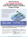
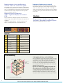
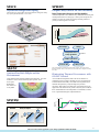
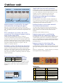
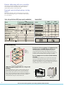
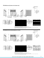
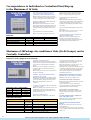
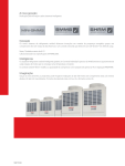
DAIYA
Inverter driven, Multi-indoor-unit,Climate Control KX2-System
(CE&NON-CE/TYPE)
CATALOGUE NO:00P009/D
: http://splitoff.ru/tehn-doc.html
Introducing the
"New Refrigerant Model"
for the global environment!
Achieving the industry's smallest
compact design.
To respond to global environment issues, such as ozone layer destruction,
which are currently encompassing the air-conditioner environment, MHI
has newly developed the scroll inverter driven multi-indoor unit KX2
Series to handle alternative refrigerants. This new series uses the nonozone layer destructing new refrigerant R407C. During development of
compatible models, the air-conditioner was reviewed
from various aspects such as air-conditioning
performance, shape and size.
Using this "New Refrigerant Model"
created with MHI's air-conditioning
technology as a stepping stone,
we plan to structure an energy system
sensitive the global environment.
R407C Alternative
Refrigerant Models
R22 Refrigerant Models
FDCP140HKXE2B
FDCP224HKXE2B
FDCP280HKXE2B
FDCJ140HKXE2B
FDCJ224HKXE2B
FDCJ280HKXE2B
New Alternative Refrigerant Models. New alternative refrigerant multiindoor unit with enhanced energy efficiency (COP) through improved
compressor and heat exchanger performance.
Table of connectable units
No. of connectable units
Model
Operation outdoor
air temperature range
Indoor unit
No.of
connectable
units
Connectable
capacity
Variation
8 unit
70~182
Min.22 model
M ax.160 model
Cooling
Heating
-5c
-15cWB
New
alternative
refrigerant
R407C
model
P140HKXE2B(5HP)
J140HKXE2B(5HP)
Max.
level
difference
P224HKXE2B(8HP)
J 224HKXE2B/D(8HP)
13 unit
P280HKXE2B(10HP)
J 280HKXE2B/D(10HP)
16 unit
112~292
~
FDC
100m
43c
18.5cWB
Min.22 model
Max.280 model
140~364
When the system is simultaneously operated with the capacity exceeding 100% of the outdoor unit,
the performance of each indoor unit will decrease slightly.
1
Max.
piping
length
KX2
~
The multi KX2 Series, a "new alternative refrigerant model", is
now available. A high COP has been achieved by mounting a
newly developed high efficiency compressor in the outdoor unit
and by improving the heat exchanger performance. Furthermore,
the industry's smallest compact design has been incorporated for
the indoor unit, by that improving the installation and
transportation performance. The number of connectable indoor
units has been increased, allowing flexible designs. Four models
from 5hp to 10hp have been prepared as the "new alterrative
refrigerant R407C models".
: http://splitoff.ru/tehn-doc.html
50m
100m
(130m)
*Custom order
Outdoor unit
Technology developed to ensure
high reliability
A high reliability is ensured with the new alternative refrigerant
model with the following means.
1.Increased compressor motor torque,
2.Increased withstand level of the refrigerant system
(piping, function parts),
3.Improvement of the high-pressure protection control, 4.Optimizing
of the heat exchanger sensor position, and 5.Incorporation of newly
developed compressor oil, etc.
Use of multiple compressors to increase
the operating frequency range
Two vertical scroll compressors are mounted in the
8 and 10hp (224 and 280 model), allowing fine energy saving
operation from 25Hz. Furthermore, by downsizing the inverter, the
generation of high frequencies is suppressed. If the non-inverter
compressor should fail, emergency operation is possible using only
the inverter compressor.
Outstanding low sound levels
with newly developed large fan
The newly developed 570mm diameter large fan, realizes low sound
levels of 59dB, the lowest in the industry. (Approx. 2db reduction
compared to current 10hp model.) The silent mode that allows the
operation sound to be reduced 2 to 3db is also available.
Improved installation and construction
performance with ultra-compact design
The 8 and 10hp (224 and 280) outdoor unit height has been
reduced from 1,700mm to 1, 450mm by changing the heat
exchanger to a rear panel single face heat exchanger. Now the size
of the multi-KX unit is the same as the MHI’s 8 to 15hp outdoor
unit (224 to 400) class for stores. The width of the 5hp (140) has
also been downsized.
Remote addressing with new controller
If the remote controller and indoor unit are connected one-on-one,
the address can be decided from the remote controller without
setting switches on the indoor PCB.
Demand control function
with high energy saving effect
The compressor is forcibly turned OFF by external signals to
correspond to peak cuts during the summer.
Indoor/outdoor connection unmatch
check function mounted
Heating operation up to an outdoor
temperature of -15C
An indoor/outdoor unmatch check function that automatically
checks each module whether the
indoor/outdoor unit setting and piping system are correct during
the trial operation has been mounted.
Heating operation is also possible to an outdoor temperature of 15C, so the unit can be used even in cold climates. Cooling
operation is also possible up to an outdoor temperature of -5C,
so cooling/heating can be carried out year-round.
1,700
1.The level difference of the outdoor unit and indoor unit is
maximum of 50m, and an one way length of 100m is possible.
When custom orderd. one way length of up to 130m is possible,
making this the longest piping specification in the industry.
2.The piping length after the first branch has been extended up to
40m as a standard.
1,450
130m long piping specifications
( custom order )
1,350
600
Conventional model
: http://splitoff.ru/tehn-doc.html
1,350
600
New model
2
Improvement of air-conditioning
control with CnT connector signal
Improved indoor unit control
By inputting the CnT signal, the unit operability enable/prohibit
is controlled making control from a commercially available timer
easier. A cooling/heating forced operation mode has been added
so that forced control of only the operation mode is possible
with no "pressed-first priority".
This control stops the fan when the heating thermostat turns
OFF. Besides reducing the sound of refrigerant flowing in the
indoor unit, and taking measures to prevent overheating, the
indoor unit control has also been improved such as the addition
of a function to stop only the relevant indoor unit when a drain
error occurs.
Improved service function
with 7- segment display on outdoor
PCB
Option
Service information is digitally displayed on the outdoor unit
with three digits, allowing the serviceability to be improved and
speeded up.
*Details on 7-segment display ... Operation frequency, error
display, each temperature data, current temperature, etc.
Preparation of built-in type high
frequency harmonics measure parts
Please contact the MHI Sales Office for details.
Display data
0
Inverter operation
frequency or error code
8
SV1
1
Heat exchanger temperature
9
SV2
2
Outdoor temperature
10
63H1
3
Dome lower (CM1)
temperature
11
63H2
4
Discharge pipe (CM1)
temperature
12
5
Discharge pipe (CM2 )
temperature
13
NO. of connected
indoor units
6
CM (CM1) current
14
Compressor operation Hz
(full load conversion value) FK
7
CT (CM2) current
Workability
130m piping for large scale buildings
Outdoor unit
Level difference
between
indoor units 15m
The level difference of the outdoor unit and indoor unit is 50m
(*), and the one way length is 100. With custom orders, a long
piping design of up to 130m, the longest in the industry, is
possible. The level difference between indoor units can also
be set to 15m. (The piping length after the first branch has
been changed from the conventional 30m to 40m. Contact the
MHI Sales Office for details.)
By the use of the 4-way piping exit option for
the outdoor unit, a flexible layout can be set
Level difference
50m, one way
length 100m.
Indoor unit
A 4-way piping exit ports from the outdoor unit has been
prepared allowing the outdoor unit installation position to be
decided according to the installation conditions. The piping
exit position can be selected from front, back, right, or bottom.
*This is 40m when the outdoor unit is lower.
3
: http://splitoff.ru/tehn-doc.html
SPACE
SPEEDY
Layout-free Refrigererant Piping
Unique Fuzzy Control for Full Flexibility
The branch type piping makes the system flexible enough to satisfy
any layout plan on the floor or in a room.
Rapid Temperature Response and High Stability
An intake temperature sensor automatically controls both the existing and
set temperature based on a "fuzzy logic". With a speed of response and
stability previously not possible, the system powerfully performs to
provide you with a high level of comfort.
Output Value
Fuzzy
Conventional
(Suction thermistor)
Temp.
Set Temp.
Temp. difference
Temp. gradient
Operation
FUZZY operation
Inverter Hz
SILENT
MHI's High Technology Achieves a
Quietness for Both People and the
Environment
Large diameter fan developed by MHI operates efficiently. Very little
resistance to air flow assures extremely quiet operation. Even
at low speed,
Model FDTJ
28's sound level
is only 34dB.
*E.E.V.pulse keeps the unit operating at the optimim condition. The system uses an
electronic expansion valve in indoor units to control the flow rate of refrigerant according
to the load.
Eliminating Thermal Unevenness with
ON-OFF Control
An air-conditioned temperature tends to be uneven when the airconditioning system is simply controlled on or off. This problem has
remained unsolved until today. Now, MHI's new temperature sensor
eliminates this problem by swifty checking for any thermal
unevenness. Other effects of an indoor unit on-off operations are also
suppressed to the minimum level possible. Thus, the system conditions
the air and maintains the room temperature at a comfortable, constant
level. A sophisticated design for sophisticated users.
30
Air Blow Direction
27
Using an adapter
Room air
temp. l (c)
SYSTEM
Standard
E.E.V.pulse*
Heating
Legend
23
Vertical blow
20
Fuzzy control
Conventional
Set temp
Horizontal
blow
: http://splitoff.ru/tehn-doc.html
4
Breakdown of system components
Example of KX2 system
FDCP140HKXE2B
FDKP45HKXE2
RCD-HKX-S-E
DIS-1KX30-E
DIS-1KX10-E
5HP
Outdoor unit
Indoor unit
Remote controller
Branch pipe
Branch pipe
Example of KX2 system
x1
x3
x3
x1
x1
10HP
Outdoor unit
Indoor unit, including panel
Remote controller
Branch pipe
Branch pipe
FDCP280HKXE2B
FDTWP36HKXE2
RCD-HKX–S–E
DIS-1KX30–E
DIS-1KX10–E
x1
x8
x8
x6
x1
Selection of branch pipe
Selection of the independent branch pipe set
(When five FDTP56HKXE2 units are connected to FDCP280HKXE2B)
4
3
Branch pipe
2
B
A
1
Downstream
Upstream
C
FDC P280HKXE2B
FDT P56HKXE2
FDT P56HKXE2
FDT P56HKXE2
FDT P56HKXE2
The branch pipe size is selected
from the downstream B and C
total (=A) capacity.
FDT P56HKXE2
1
Downstream total capacity is 280 (56 type x 5 units) > The downstream is 101 or more, so select DIS-IKX30-E
2
Downstream total capacity is 224 (56 type x 4 units) > The downstream is 101 or more, so select DIS-IKX30-E
3
Downstream total capacity is 168 (56 type x 3 units) > The downstream is 101 or more, so select DIS-IKX30-E
4
Downstream total capacity is 112 (56 type x 2 units) > The downstream is 101 or more, so select DIS-IKX30-E
Optional independent branch pipe set
Corresponding outdoor unit
(horsepower)
FDC
140HKXE2B(5)
224HKXE2B/D(8)
280HKXE2B/D(10)
Type
When downstream is less than 101
DIS-1KX10-E
When downstream is 101 or more, 371 or less
DIS-1KX30-E
The branch pipe must be used according to the total downstream capacity of the indoor unit.
(One set is always required for each branch.)
Outdoor unit
[ R407C ] FDCP140HKXE2B
[ R22 ]
[ R407C ] FDCP224HKXE2B
FDCP280HKXE2B
FDCJ140HKXE2B
[ R22 ]
FDCJ224HKXE2B
FDCJ280HKXE2B
(STOCK ONLY)
FDCJ224HKXE2D
FDCJ280HKXE2D
(NEW)
5
MHI Part No.
: http://splitoff.ru/tehn-doc.html
Specification
KX2 series
R407C
R22
Model
FDCP140HKXE2B<5hp>
FDCJ 140HKXE2B<5hp>
FDC P224HKXE2B<8hp>
FDCJ224HKXE2B/D<8hp>
3 phase 380/415V 50Hz
Power supply
FDC P280HKXE2B<10hp>
FDCJ280HKXE2B/D<10hp>
Cooling capacity 1)
kW
14.0
22.4
28.0
Capacity Heating
Standard
capacity
kW
16.0
25.0
31.5
6.8
9.8
11.7
5.7
8.3
9.4
Power
Cooling
kW
consumption Heating Standard
Outline
dimensions
Heightxwidthxdepth
1450x1350x600
mm
1450x690x600
Weight
kg
150
250
265
Compressor motor outputxunits
kW
3.5x1
3.5+2.2
3.5+3.75
Blower motor outputxunits
Air flow
W
100
m3/min
90
dB
56
Operation sound 2)
Connecting pipe
180
58
59
p12.7x1.0(flare connection)
p9.52x0.8(flare connection)
Liquid piping
p19.05x1.0(flare connection)
Gas piping
Allowable refrigerant piping length
100x2
p28.58x1.4(Blazing connection)
p25.4x1.2(Blazing connection)
m
100
Note 1)The cooling and heating capacities are the values when connecting and operating the rated capacity indoor unit under ISO TI conditions .
Note 2)The operation sound complies with the ISO Standards, and is the value converted to the equivalent anechoic chamber value. When measured in the actually installed state,
the value is normally larger than the display value due to the effect of surrounding noise and echo.
FDCP140, FDCJ140
Refrigerant piping connection opening dimensions
(Plane view)
Rear surface
Signal cable connection terminal block
Power connection terminal block
(Unit: mm)
Installation example
L3
L4
( Service
space )
L1
L2
L3
L4
H1
H2
H3
H4
Wall height H4
Wall height H2
Air inlet
L2
I
II
III
Open
Open
500
0
0
0
300
300
300
Open
500
0
Dimension
Wall height H3
L1
-
-
1000 or less
No limit
No limit
No limit
No limit
No limit 700 or less
-
No limit
No limit
Wall height H1
Note ) If the installation example III wall height H1 and H3 exceed the limit value,
set L1 and L3 as follows. L1=H1 - 500 L3 = 300 + (H3-700)/2
Note that if L3 = 600 is exceeded, the wall height H3 limit does not apply.
Symbol
Details
A Refrigerant gas piping connection opening
B Refrigerant liquid piping connection opening
C Refrigerant piping outlet
D Refrigerant gas piping outlet
F Refrigerant liquid piping outlet
G Power inlet
H Power inlet
J Piping and wiring downward exit hole
K Wiring inlet
L Anchor bolt hole
M Drain drainage hole
N Drain drainage hole
p19.05 (flare)
p9.52 (flare)
p88 Two places
p39
p25
p35 Two places
p50
p65
p50
Four places for M10
p20 Four places
p50
FDCP224QP280, FDCJ224QJ280
Refrigerant piping connection opening dimensions
(Plane view)
Rear surface
Signal cable connection terminal block
Power connection terminal block
(Unit: mm)
Installation example
Wall height H3
L2
( Service
space )
Wall height H1
L3
L4
L1
Wall height H4
Wall height H2
Air inlet
Dimension
L1
L2
L3
L4
H1
H2
H3
H4
I
II
III
Open
Open
500
0
0
0
300
300
Open
500
0
-
-
1000 or less
No limit
No limit
No limit
No limit
No limit 700 or less
-
No limit
300
No limit
Note ) If the installation example III wall height H1 and H3 exceed the limit value,
setQL1 and L3 as follows. L1=H1 - 500 L3 = 300 + (H3-700)/2
Note that if L3 = 600 is exceeded, the wall height H3 limit does not apply.
Symbol
Details
A Refrigerant gas piping connection opening
B Refrigerant liquid piping connection opening
C Refrigerant piping outlet
D Refrigerant gas piping outlet
F Refrigerant liquid piping outlet
G Refrigerant gas piping outlet
H Refrigerant liquid piping outlet
J Power inlet
K Power inlet
L Piping and wiring downward exit hole
M Wiring inlet
N Anchor bolt hole
P Drain drainage hole
R Drain drainage hole
: http://splitoff.ru/tehn-doc.html
p25.4 (brazing)
p12.7 (flare)
p88
p39
p25
p65
p50
p35 Two places
p50
p100
p50
Four places for M10
p20 eight places
p50
6
Outdoor unit
Applicable for renewal expansion.
Inverter unit
Constant-speed unit
Constant-speed unit
Since the multi system has such a high degree of design freedom
as the outdoor unit can be installed and connected at the site, an
easy work to additionally connect the outdoor unit will solve the
problem even if the air conditioning load increases after
installation or the air conditioner is added in the future.
Heating operation up to an outdoor
temperature of -15ºC
Indoor unit
(Liquid pipe/gas pipe)
(Liquid pipe/gas pipe/equalizing pipe)
Heating operation is also possible to an outdoor temperature of 15C, so that unit can be used even in the cold climates. Cooling
operation is also possible up to an outdoor temperature of -5C, so
cooling/heating can be carried out year-around.
Improvement of workability through
concentration of refrigerant pipes
Indoor/outdoor connection unmatch
check function mounted.
Multi X2 is a system which achieves the large capacity multiapplication of plural units with the outdoor unit of 10 horsepowers as
basic. This makes it possible to concentrate the refrigerant pipes into
one pipe.
An indoor/outdoor unmatch check function that automatically
checks each module whether the indoor/outdoor unit setting and
piping system are correct while the trial operation has been
mounted.
It has improved the reliability of the work.
This contributes to reduce the work
expense of the refrigerant pipes and the
space of the pipe shaft.
Improvement of air-conditioning
control with CNT connector signal.
Complete pursuit for the reliability of the air conditioner
To solve the maldistribution of the refrigerator oil and refrigerant
among the units, the oil return control, oil equalizing operation and
refrigerant accumulation/collection control are applied. In addition,
the oil level control of the compressor and the optimal control of the
refrigerant accumulation amount are also applied. Thus, the
reliability is completely improved.
By inputting the CNT signal, the unit operability enable/prohibit is
controlled making control from a commercially available timer
easier. A cooling/heating forced operation mode has been added so
that forced control of only the operation mode is possible with no
pressed-fist priority.
Reliable system with back-up operation
Service information is digitally displayed on the outdoor unit with
three digits, allowing the serviceability to be improved and speed
up.
Details on 7-segment display ... Operation frequency, error display,
each temperature data, current temperature, etc.
The advantage of the system of plural outdoor units is the back-up
operation. The back-up operation is provided to operate another
outdoor unit in the emergency mode even if any outdoor unit should
be troubled. As the highly reliable safety function, the multi type
large capacity prevents the air conditioning system from a complete
stop as a fatal trouble.
Improved service function with
7-segment display on outdoor PCB.
Demonstration of high-efficiency
Inverter unit
inverter
10HP
J280HKXE2-K
(main unit)
control
Constant-speed unit
10HP
J280HKXE2-KT
(sub unit)
The inverter
compressor is equipped in the main unit, and the capacity control
type compressor is equipped in the sub unit. Together with the
minute capacity control, COP is improved during partial load
operation.
Expansion of
constant-speed
units
Display data
Indoor unit
Inverter operation
frequency or error code
SV1
Heat exchanger temperature
SV2
Outdoor temperature
63H1
Dome lower (CM1)temperature
63H2
Discharge pipe (CM1) temperature
63L
Discharge pipe (CM2 ) temperature
Number of connected indoor units
CT (CM1) current
Compressor operation HZ
(Full load conversion value)
CT (CM2) current
The above are sequentially displayed
: http://splitoff.ru/tehn-doc.html
8
Remote addressing with new controller.
If the remote controller and indoor unit are connected one-onone, the address can be decided from the remote controller
without setting switches on the indoor PCB.
Demand control of high energy saving
effect
Whether the demand is valid or invalid can be set at each sub
unit. On the 30-hosepower type, it is selectable at three steps of
0%, 33% and 66%.
Basic unit specification of KX2 (large-capacity combination)
Inverter unit
Model
Power supply
Cooling capacity
Capacity
Heating capacity
Outline dimensions
Height X Width X Depth
Weight
Compressor motor
output X Number of units
Blower motor
output X Number of units
Inverter Multi
10HP
Constant-speed unit
3phase 380v 50HZ
Blow rate
Operating sound
Connection Liquid pipe
Gas pipe
piping
Tolerable length of refrigerant piping
20HP
30HP
Model
Cooling capacity
Heating capacity
Electric power for cooling
Electric power for heating
Cooling operation current
Heating operation current
Starting current
Coefficient of electric
power for cooling
Coefficient of electric
power for heating
Branch pipe set to combine the separately available outdoor unit
Total capacity of outdoor units
Part No.
Workability
By the use of 4-way piping exit option for the
outdoor unit, a flexible layout can be set.
Outdoor unit
Between
indoor units
level difference
between
indoor units 15m
A4-way piping exit ports from the outdoor unit has been
prepared allowing the outdoor unit installation position to be
decided according to the installation condition. The piping exit
position can be selected from front, back right, or bottom.
It is as compact as it can be carried with the
elevator.
Level difference
50m, total
length 100m.
Indoor unit
On the multi KX combination series which achieves the large
capacity by installing plural outdoor units of 10 horsepowers,
the installation dimension can be calculated from two kinds of
modules. One module is so compact a design of the top class in
the industry that it can be carried with the elevator.
* 40m in the following case of the outdoor unit
100m long piping applicable for a large-scale
building
900
1,450
At the height difference of 50m (*) between indoor unit and
outdoor unit, the total length is 100m. The level difference
between indoor units can be set to 15m between the indoor
units. (The pipe length beyond the first branch is changed from
existing 30m to 40m. Please contact sales office for details.)
* 40m in the following case of the outdoor unit.
1,350
1,500
1,350
Ordinary elevator
9
: http://splitoff.ru/tehn-doc.html
600
New model
FDCJ280 basic unit (inverter unit and main unit)
Refrigerant piping outlet
dimension (top view)
Back side
Connection terminal
of power supply
(Unit: mm)
Installation example
Wall height
Dimension
L1
L2
L3
L4
H1
H2
H3
H4
Blow-in
Service space
Wall height
Content
(Soldering)
Refrigerant gas piping connection opening
Refrigerant liquid piping connection opening
(Flaring)
Equalizing oil piping connection opening
(Flaring)
Refrigerant piping outlet
Refrigerant gas piping outlet
Refrigerant liquid piping outlet
Two places
Power inlet
Power inlet
Piping and wiring downward exit hole
Wiring inlet
Anchor bolt hole
Four places for M10
Drain exhaust hole
eight places
Drain exhaust hole
Wall height
Symbol
Wall height
Be sure to securely fasten the unit with anchor bolt.
If any strong wind blows, position the exhaust port at a right angle against the wind.
Provide a space of 1m or more above the unit.
The equipment nameplate is positioned on the bottom of the front side.
The refrigerant piping (both gas and liquid sides) are connected under the procurement at the site.
If the installation example III wall height H1 and H3 exceed the limit value, set L1 and L3 as follows. L1 = H1 - 500
However, if L3 = 600 is exceeded, the wall height H3 is not limited.
I
II
III
Open
Open
500
0
0
0
300
300
300
Open
500
0
-
-
1000 or less
Not limited Not limited Not limited
Not limited Not limited 700 or less
-
Not limited Not limited
L3 = 300 + (H3 - 700)/2
FDCJ280 basic unit (Constant-speed unit, sub unit)
Refrigerant piping outlet
dimension (top view)
Back side
Connection terminal
of power supply
(Unit: mm)
Installation example
Wall height
Dimension
Blow-in
Service space
Wall height
Content
Refrigerant gas piping connection opening
(Soldering)
Refrigerant liquid piping connection opening
(Flaring)
Equalizing oil piping connection opening
(Flaring)
Refrigerant piping outlet
Refrigerant gas piping outlet
Refrigerant liquid piping outlet
Power inlet
Two places
Power inlet
Piping and wiring downward exit hole
Wiring inlet
Anchor bolt hole
Four places for M10
Drain exhaust hole
eight places
Drain exhaust hole
Wall height
Symbol
Wall height
L1
L2
L3
L4
H1
H2
H3
H4
Be sure to securely fasten the unit with anchor bolt.
If any strong wind blows, position the exhaust port at a right angle against the wind.
Provide a space of 1m or more above the unit.
The equipment nameplate is positioned on the bottom of the front side.
The refrigerant piping (both gas and liquid sides) are connected under the procurement at the site.
If the installation example III wall height H1 and H3 exceed the limit value, set L1 and L3 as follows. L1 = H1 - 500
However, if L3 = 600 is exceeded, the wall height H3 is not limited.
: http://splitoff.ru/tehn-doc.html
I
II
III
Open
Open
500
0
0
0
300
300
300
Open
500
0
-
-
1000 or less
Not limited Not limited Not limited
Not limited Not limited 700 or less
-
Not limited Not limited
L3 = 300 + (H3 - 700)/2
10
New building air-conditioning
control system designed to meet
all future requirements.
A polarity-free, Two-wire Line Allows a Maximum
of 48 Indoor Units to be Incorporated in Network.
Just set the indoor and outdoor units to an address number, linking a maximum of up to 48 indoor units in a network. Only two
lines are required for wiring both inside and outside, reducing the conventional cabling to a sixth or an eighth. It fully satisfies
the air-conditioning requirements of newer, intelligent buildings, and also dramatically cuts both installation costs and wiring
shaft area.
Networking Directly with Multi KX2 Packaged Air-conditioner.
The system can be networked directly with Multi KX2 packaged air-conditioner and an optional controller.
Just connect the polarity-free, two-wire signal line
Outdoor Units
Indoor Units
FDE
Indoor Units
FDUM
FDK
FDTS
Indoor Units
FDT
FDR
Centre
Centre
Console
Console SLA-1
SLA-2
11
Optical
Controller
FDTW
Controller
Network
Remote
Controller
: http://splitoff.ru/tehn-doc.html
New
Standard remote controller
(optional item)
Use of a clear LCD panel allows easy recognition of operating states.
The remote and timer operation indications are displayed even while
the air conditioner is being stopped.
Operation mode indication
Filter sign
Used to indicate a selected operation mode.
Indicated when cleaning of the air filter is needed.
Remote indication
Air volume indication
Indicated while the air conditioner is being
controlled using theindividual remote controller.
(This indication is also displayed even while the air
conditioner is being stopped.)
Indicates the set air volume.
Heating ready indication
Indicated when the cooling air blow is prevented.
Operation / Check lamp
Center indication
This lamp is lit in green during operation
and flashes in red if an error occurs.
Indicated while the air conditioner is being
controlled using the optional center console.
Run/Stop switch
Timer indication
Operation is possible even though
the cover is not opened.
Indicates the contents of timer operation.
(Contents of timer operation are displayed even while
the air conditioner is being stopped.)
Intake air temperature indication
Set temperature indication
Indicates the intake air temperature.
Indicates the set temperature during normal operation.
Auto swing indication
Check switch
Indicates the swing louver status.
Used during service work.
Mode switch
Timer switch
Used to select a desired mode.
Used to select the contents of timer operation.
Air volume switch
Remote controller built-in sensor
Used to set an air volume.
Set switch
Temperature set/ Time set
Used to set the timer time.
Used to set the room temperature and timer time.
Auto swing switch
Used to start and stop the swing louver.
Functionality
oA thermostat function, which can be switched between the
air conditioner return air sensor and remote controller
built-in sensor is provided.
oA power failure compensation function is provided as
standard function. If a power failure occurs during
operation, and then is recovered, operation is restarted
according to the settings before the power failure
occurrence.
(However, it is necessary to set the timer auto swing again.)
One indoor unit can connect two remote controller each.
Remote-controller :Model name
FDR and FDUM series are not provided with AUTO
SWING switch = RCD-HKX-E2
FDFL series are also not provided with AUTO SWING
switch = RCD-HKXFL-E2
Except above indoor = RCD-HKX-S-E2 (with Auto swing
switch)
Operability
oThe same key is used for timer setting and room
temperature setting. As the number of indication keys
with rotary selection was reduced, the display screen was
enlarged, improving operability. Additionally, touch
feeling of operation keys is much improved.
o2 remote controllers can be connected to one indoor
unit (or one indoor unit group).
Cover opener
A handle is provided on the cover, resulting in
improvement of open/close operability.
Receiver amp Kit (RCND-KIT-HE)
By mounting the receiver amp kit (option) ,wireless use
is possible with all series.
oBoth the standard remote controller and wireless
remote controller can be installed simultaneously for one
indoor unit.
oThe wireless remote
controller is enclosed.
oThe timer is indicated by the
12-hour system, AM or PM.
Additionally, it is also possible
to set the time in minutes.
: http://splitoff.ru/tehn-doc.html
12
Correspondence to Individual or Centralized Start/Stop up
to the Maximum of 16 Units
Center Console
SLA-1-E
This center console provides the operation,
stop, and inspection for the package airconditioners up to the maximum of 16 units.
connected on the same network of the Super Link.
OIn the case of consecutive addresses, any number
from 1 to 16 units can be set per one [SLA-1-E].
OSixteen operation switches are used to control the
package air-conditioners up to the maximum of sixteen
(16) units, which improved the operability sharply.
Considerate design for power outage
compensation
Operating condition confirmation function per
individual standard unit
OThe sixteen (16) LEDs display the Nos. of units
being operated. They light green during operation, red
during inspection (error), and light-off at stop or nonconnection to indicate the condition of each unit at a
glance.
Correspondence to each floor installation
OSLA-1-Es up to the maximum of six units can be
Combination
Kind
Combination
OK
OK
OK
Commercial timer
Weekly timer(SCA-WT-E)
SLA-2A-E
Thin and compact design that does not occupy
much space
OA compact design of H: 120 mm (4.72 in.) x W:120
mm (4.72 in.), and 15 mm (0.6 in.) thick .
The wiring installation work is simplified by
virtue of the Simple System.
OTying-in the center console to the Super Link
Network can be accomplished directly by only
connecting the signal wire of non-polar two-wire type,
which simplifies the wiring installation work.
Remarks
Required
Standard Remote Control
OThe compensation function for the power outage is
equipped as the standard features. In the event that there
is a power outage during operation, the operation is
restarted after restoration using the information stored
in the memory.
Batch controlled ON/OFF only
See below mentioned description on SLA-2A-E.
Maximum of 48Package Air-conditioner Units (1to16 Groups ) can be
Centrally Controlled.
A new type that a weekly timer can be connected without an interface. The remote control "prohibit/allow"
function is newly equipped on the SLA-2A-E.
Useful thin and compact design
Center Console
SLA-2A-E
OSixteen operation switches are used to provide the
batch control of 16 groups at the maximum (Number of
object is 48 units), which improved the operability
sharply.
OA large, easy-to-see LED display is adopted. The
operation condition and contents of setting can be
confirmed easily.
OThe center console can be connected at anywhere on
the Super Link Network.
Individual control by New Standard Remote
Control is possible as well.
OIn addition to the individual and centralized control,
the individual control from the New Standard Remote
Control is possible by setting to the center & remote.
OThe New Standard Remote Control can be
eliminated.
Combination of SLA-1-E and SLA-2A-E
SLA-1-E
SLA-2A-E
Case 1
6 units
0
Case 2
0
3 units
Case 3
3 units
1 unit
Case 4
2 units
1 unit
The SLA-1 makes ON/OFF control possible with
each floor as a unit.
OIn the case that the center console SLA-2A-E is set to
the individual or each floor, connecting the SLA-1Emakes the ON/OFF control of individual/each floor
possible from the SLA-1-E.
New Standard Remote Control
13
Combination
Individual
or
plural connections
SLA-1-E
OK
SLA-2A-E
OK
Weekly timer(SCA-WT-E)
OK
Commercial timer
OK
External input
OK
Demand control and emergency stop control
ODemand control by the external signal is possible.
OEmergency stop control is possible as well.
Considerate power outage compensation
OThe power outage compensation function is provided
as the standard features.
In the event that there is a power outage during
operation, the operation is restarted after restoration
using the information stored in the memory.
Correspondence to program operation
OBy connecting a separately sold weekly timer, the
program operation per group up to 16 groups can be
performed.
Expansion of network control
OFree connection is possible from 1 to 48 units per
Combination with SLA-2A-E
Kind
one group and up to the maximum of 16 groups (The
total number of units of the whole group is 48.) even
though the addresses are not consecutive.
OUp to the maximum of 3 unit of SLA-2A-E can be
connected in the same Super Link Network.
OThe Super Link can stop/start and monitor the package
air-conditioner individually, in batch or by the group, it
also can control the operation mode and temperature
setting. Thus, the Super Link creates advanced airconditioning control system.
The wiring installation work is simplified by
virtue of the simple system
OThe non-polar two-wire type simple system greatly
reduces the wiring installation work.
Remarks
Possible without connection
Connection with the weekly timer without
interface
Emergency stop by input from the non-voltage "a" contact,
demand control, and allowed/ prohibited
OAn interface, which has been necessary until now,
became unnecessary.
The weekly timer can be connected easily. The SLA-2AE alone is equipped with the equivalent function with the
old SLA-2-E.
: http://splitoff.ru/tehn-doc.html
Remote controller function list
Center lock function is equipped.
ODisconnecting the jumper wire (J1) of SLA-2A-E, the
demand function is converted to the center lock
function.
OWhen the non-voltage contact input is supplied from
the commercial timer to the demand input contact of
SLA-2A-E, the unit which has been set to demand
setting in SLA-2A-E is converted to the center mode.
ODuring the center lock, the center/remote changeover
switch becomes invalid.
Equipment
Item
Center console SLA-1-E
Center console SLA-2A-E
Individual control (Number of packaged air-conditioners)
Group control (Number of groups)
Start/stop (simultaneous, group and individual)
Group setting
Operation mode (Cooling, dehumidification, heating, blowing and automatic)
Priority indication (Center/remote)
Control
New weekly timer
Operation
Room temperature setting
Wind volume switching
Forced stop
Stop
Power failure stop/recovery control
Contact input
ON
Demand control
Filter sign reset
OFF
Check sign reset
Indoor unit
Operation
Operation condition (Operation/stop)
Priority indication (Center/remote)
Stop
Prohibited
Allowed
"Center" between this interval
Indoor unit
SLA2A-E
Monitoring
Remote control
operation
Allowed
Operation mode (Cooling, dehumidification, heating, blowing and automatic)
Wind volume (Fast, strong and weak)
Set temperature
Automatic swing (ON/OFF)
New weekly timer
Room temperature display
(Non-voltage)
contact input
Filter sign
Commercial timer, etc.
R
Check sign (Error/warning)
The Indoor Units up to the Maximum of 48 Units per One System
can be Controlled.
Weekly timer
(SCA-WT-E)
Daily/weekly program can be set by the
standard operation.
OOperation reservation for one week can be set.
OThe ON/OFF time can be set for three times a day
with a minute as the smallest unit. Setting OFF only
also prevents forgetting to set the off time.
OSetting the operation reservation day of the week to
the holiday setting makes it possible to temporarily
cancel an operation reservation.
OThe current time, day of the week, and a 24-hours
time graph for the day's program operation time can be
displayed.
Using together with the SLA-2A-E makes it
possible to set a schedule for each group.
Function item list
OOne unit of weekly timer can control the maximum
of 48 indoor units in one system. And furthermore, by
combination with SLA-2A-E, the schedule setting for
each group (16 groups at the maximum) becomes
possible.
Monitor mode
Example of combined system with SLA-2A-E
Display of current day of the week, time, and
program condition
OIt is necessary to use together with SLA-2A-E for the
group start/stop by the weekly timer. The allowable
number of unit that can be connected to SLA-2A-E is
only one unit per one system and connection exceeding
Time setting
Setting of current day of the week, and time
this is not allowed.
OSwitch the control changeover switch (SW 9) to the
appropriate side considering whether SLA-2A is used
together or the disposition after power outage recovery.
Power outage compensation function is equipped.
ODuring power outage or the power is off, the condition
set by the weekly timer is held. After restoration, the
monitor mode is displayed conforming to the time when
restored.
OSwitching the control changeover switch(SW9-2) to
ON, transmits an operation (stop) command after power
outage recovery using the timer setting mode under
recovery.
When the timer setting mode (as shown in the graph
below) is 1, a stop command is transmitted because the
system is in the stop mode at power outage recovery.
When it is 2, an operation command is transmitted
because the system is in the operation mode at power
outage recovery.
OPay attention that the control changeover switch is set
to OFF at delivery, therefore no operation (stop)
command is sent after power outage recovery.
Timer setting
Setting of timer program
( Example)
Holiday setting
Setting of day of the week for the holiday
Out
Operation
1
stop
SW9=Control chahge over switch
OFF
Start/stop in batch
SW9-1
ON
The schedule and group setting for
each group by use together with
SLA-2A-E are performed at the SLA2A-E side.
In
In
In
SLA2A-E
SLA1-E
(SW9-1 and sw9-2)
SW9-1
In
Operation
SLA1-E
2
stop
Power outage duration
SLA1-E
WT-E
: http://splitoff.ru/tehn-doc.html
14
R407C Refrigerant Precautions for Servicing and Construction
1. Contaminants
take extra special care in controlling the water content
and contaminants.
2. Ester oil is used for the lubrication oil. If the
conventional oil (barrel freeze, Suniso, etc. ) mixes in,
1. Compared to the conventional refrigerant system,
large amounts of contaminants (oil, water, oxidized
film) enter the refrigerant system. Thus, when using
clean piping, or displacing the nitrogen during brazing,
sludge will form. Thus, always use dedicated tools for
the gauge manifold, charge hose, etc.
2. Gas leakage
If the refrigerant gas leaks and additional charging is
carried out, the composition of the refrigerant in the
system will change and may lead to
insufficientperformance, etc. Thus, recover all
3. Refrigerant piping material
For the other refrigerant piping materials, use the JIS H
3300 "Copper Pipe and Steel Alloy Seamless Pipe" C
1220 type copper pipe. The pressure is somewhat higher
than the conventional refrigerant , so select a copper
pipe with a thickness that corresponds to the new
refrigerant and can withstand the pressure.
refrigerant in the system to the outside, and recharge the
specified amount of refrigerant.
refrigerant HCFC22
New refrigerant HFC407C
Refrigerant Conventional
(single refrigerant)
(3-liquid compound refrigerant)
Ester oil
MIneral oil
Synthetic oil (poly olester)
Condensing
pressure
1.84MPa (18.8kg/cm2 )
2.01MPa (20.5kg/cm2 )
Refrigerant piping thickness comparison table
Copper pipe outer diameter
p6.4mm
p9.5mm
p12.7mm
p15.9mm
p19.1mm
p22.2mm
p25.4mm
Copper
pipe
thickness
Conventional refrigerant HCFC22
0.8mm
0.8mm
1.0mm
1.0mm
1.0mm
1.2mm
1.4mm
New refrigerantHFC407C
0.8mm
0.8mm
1.0mm
1.0mm
1.2mm
1.4mm
1.4mm
When selecting and laying the copper pipe, always observe the "Refrigerant Safety Rules Related Standards".
R407C Refrigerant Points for Piping Construction
Three Rules for Refrigerant
Piping Construction
Three Rules for Refrigerant Piping Construction
Dry
There is no water inside
Special caution that differs from other building facility
piping is required for the refrigerant piping. If these
cautions are ignored, trouble could occur. When
constructing the refrigerant piping, exercise special care
to make sure that the inside of the pipe is "dry", "clean"
and "tight". These three items are the "three rules for
refrigerant piping construction".
Clean
Tight
There is no dirt inside
There is no refrigerant leakage
Leak
Prevention
measures
Generated
symptoms
Cause
Items
Water
Dirt
*Water, such as rain water, enters from outside *Oxidization film during brazing
*Water forms due to condensation in the piping *Foreign matter, such as dirt dust or oil,
enters from outside
*Insufficient brazing
*Incorrect flare machining or tightening
torque control
*Clogging of the expansion valve or capillary
tubes, etc.
*Failure to cool or heat
*Deterioration of lubrication oil
*Failure of compressor
*Insufficient gas
*Failure to cool or heat
*Rise of discharge gas temperature
*Deterioration of lubrication oil
*Failure of compressor
Piping maintenance
Flushing
Vacuum drying
*Clogging of the expansion valve or capillary
tubes, etc.
*Failure to cool or heat
*Deterioration of lubrication oil
*Failure of compressor
*Same as left
*Follow the basic brazing work
*Do not use devices used with other refrigerant *Follow the basic flare machining work
*Follow the basic flange connection work
*Carry out tightness test (gas leakage)
R407C Refrigerant Construction Procedures
Precautions (1) All devices will change to the new refrigerant to prevent ozone layer destruction and global warning.
(2) As the properties of the each refrigerant differ, the specifications differ greatly. Refer to the manuals issued by each maker.
1. Confirmation before construction
1. Type of refrigerant charged in product
Old refrigerant = R22, New refrigerant = R407C
2. Confirmation of construction place and specifications
Secure the construction members and tool installation place.
3. Confirmation of required tools
The tools must be used according to the type of refrigerant.
Never use the gauge manifold, charge hose, charge cylinder
or vacuum pump with other refrigerants. Always carry
out the work with dedicated tools. (Failure to do so
could lead to trouble.)
4. Confirmation of connection piping (Set
length piping, long length piping)
Use the JIS specified piping (Refer to the Refrigerant
piping thickness comparison table) to handle the new
Table of usage possibilities (R407C )
Possibility of
conventional
device use
Gauge manifold
x
Charge hose
x
Charge cylinder
x
Gas leakage detector
Vacuum pump
Pump with back flow prevention
15
refrigerant. Confirm that the piping end has been treated
(cap or tape) for the long piping. When using recessed
piping construction, always cover the pipe end (with
cap or tape).
Table of usage possibilities (R407C )
Possibility of
conventional
device use
Remarks
The pressure increases, and the fitting specifications have been changed.
Remarks
Flare tool
Bender
Not compatible with current part
Common with 134a HFC compliance is required as chlorine is not contained
Usable if backflow preventing adaptor (for refrigerant) is installed
Refrigerant cylinder
R407C
The refrigerant name is described on the outside, and the paint color has been changed
Torque wrench
Cutter, reamer
Welder, nitrogen cylinder
: http://splitoff.ru/tehn-doc.html
2. Flare connection
Cautions
(1) Confirm that there are no scratches or dirt, etc., on
the flare and union section.
(2) When applying lubrication oil on the inside and
outside of the flare, always use the same lubrication oil
as that used in the installed air conditioner. Use of
different oil will cause the lubrication oil to deteriorate
and the compressor to burn, etc.
Connection section (A)
Connection section (B)
Copper pipe
Flare nut
Half union
Male side
Oil application (ease the nut friction)
Female side
Spanner
Torque wrench
Oil application (improve the
seal face sealing)
Flare nut
Apply the lubrication oil on the inside of the flare and
on the outer surface of the union.
Always tighten the connection section with the correct installation torque.
3. Brazing work
3. Always seal (using rubber plug, etc.) the gap between
the piping material and nitrogen conduit to prevent the
backflow of nitrogen gas.
4. When flowing the nitrogen gas, do not stop it at the end
of the piping side. Instead, leave this side open.
5. The guideline for the nitrogen gas is 0.05m/h or
0.02MPa(0.2kg/cm2) or less with the pressure-reducing
valve.
6. After working, flow the nitrogen gas until the piping
cools down (to a point where the pipe can be touched by
hand).
7. Remove all flux after brazing work.
Nitrogen gas
(1) Brazing work requires a high level of technology and
experience. The work must be carried out by a worker
who has completed the “Gas Welding Skill Seminar”
specified under the Labor and Sanitation Laws, following
theoretical knowledge.
(2) Brazing work must be carried out while flowing dry
nitrogen gas (N2) so that an oxidized layer does not form
on the inside of the piping material.
(3) Work methods to prevent oxidization.
1. Install a pressure-reducing valve and flow meter on the
nitrogen cylinder.
2. Use a 6.35 mm copper pipe for the pipe led to
the piping material, and install it on the flow meter of the
cylinder side.
Flow meter
M
Stop valve
6.35 pipe
From nitrogen cylinder
Nitrogen gas
Piping
Rubber plug
4. Tightness test
After completing all piping connections, always carry out
a tightness test for the reffrigerant piping, and confirm
that there is no gas leakage.
Note) For pipes having valves that open with the
continuity of a solenoid valve, etc., carry out the
leakage test, vacuuming and gas charge in the
continuity state.
(1) Tightness leakage test procedures
Always observe the "maker indicated value" for the
"applicable gas type", "high pressure side", "low pressure
side", and "pressurizing time".
(2)Cautions
1. After welding, if pressure is applied before the piping
temperature drops, the pressure will drop after the pipe
cools.
2. The pressure will rise and drop according to the
outdoor temperature. (The constant container gas is
proportional to the absolute temperature. )
*Absolute pressure at measurement = absolute pressure at
pressurizing (273C + temperature at pressurizing/273C+
temperature at measurement)
(3) Locating a leak and its repair
1. If there is a leak, use soap water, etc., to find and
repair the leakage section in the welding sections, flare
section, flange section and each unit section. (Always
flow nitrogen when carrying out repairs that require
welding.)
2. If the leakage place is difficult to find, mix Freon
gas, and find the approximate leakage place with a leak
tester, etc.
3. Always carry out the leakage test before embedding
piping recessed in pits, etc.
(2) Gauge manifold
Use gauge manifolds and charge hoses dedicated for the
HFC–based refrigerant. If tools used with HFCF22
refrigerant are used, the device could be damaged by
deteriorated lubrication oil (mineral oil) that is
incompatible.
5. Vacuuming
Gas leakage test
Charge of specified
amount of refrigerant
Tightening of piping
connection sections
Charge of small
amount of refrigerant
Installed gauge's
needle must not
rise for 5 min.
Tightness check
10 to 154 min.,
7500 mmHg or more
Completion
of vacuuming
Start of
vacuuming
Basic work flow
Installation of
gas charge device
(1) Vacuum pump
Select an adequate vacuum pump considering the
workability and ease of use, etc. Use the capacity of the
refrigerant cycle configuring the target device as a
guideline. Fitting screw specifications: Use UNF7/16 for
the R407C fitting.
R407C Refrigerant Charging Method
1. Restrictions for charging refrigerant to system and charge cylinder from refrigerant cylinder.
Refrigerants that have restrictions in respect to the liquid-phase charging may change in composition at the gaseousphase, may not achieve the specified performance, or may damage device. Always charge liquid-phase refrigerant.
2. Liquid-phase charging methods and cautions
(1) The conventional CHFC22 is a singlerefrigerant, and there were no limits to the refrigerant state during charging.
Thus, when charging the refrigerant into the system, the following procedure is the most common.
*Invert and charge or use a refrigerant cylinder with syphon pipe.
Charge the refrigerant in the liquid state from the service port (high pressure side ) of the liquid outlet operation valve > run the compressor,
charge the insufficient amount from the service port (low pressure side) of the intake operation valve in the gaseous state.
When charging the refrigerant from the intake side, the refrigerant had to be charged in the gaseous state to prevent liquid return operation at the compressor.
(2) With the HFC refrigerant, the composition changes if
not in a liquid-phase, and thus, liquid-phase charging
is required. However, in terms of protecting the
compressor, the refrigerant at the intake side of the
system must still be in a gaseous-phase. The methods
for charging the refrigerant into the system basically
do not differ from the procedures given above. Thus,
when charging HFC refrigerant requiring liquid-phase
charging into the system, the compressor must be run,
and caution is required when charging from the
suction side.Even when charging the refrigerant from
the suction side, always draw out the refrigerant from
the cylinder or charge cylinder in a liquid state.
Actual methods are as follow:
*1. Close the refrigerant by operating the adjustment
valve on the gas cylinder, and when it is drawn into
the system, adjust so that refrigerant is gassified.
*2. There is a dedicated tool for converting the liquid
refrigerant into a mist. This tool is installed on the
cylinder or charge cylinder valve and used.
: http://splitoff.ru/tehn-doc.html
16
Connectable Indoor Units
FDTW
FDT
FDR
FDUM
FDE
FDK
FDFL/FDFU
FDTS
The direct expansion coil, the open air treatment unit and the feed air
treatment unit can be connected as indoor units for Multi KX.
How to Read a Model Name
FDEJ140HKXE2
KX2 type
export type
Heat pump
Capacity 14,000 W
J:R22
System Extensions for Diverse Needs ( Optional Parts )
oWeekly Timer
oNetwork Remote Control
oCentre Console SLA-1-E
oCentre Console SLA-2A-E
oBuilding Management System (BMS)
oDrain up Kit
17
: http://splitoff.ru/tehn-doc.html
FDE
FDFL/FDFU
Ceiling Suspended Type
Floor Standing Type
FDE Ceiling Suspended Type
Floor Type Lowboy FDFL/FDFU
OEasy retro-fit application. Low operating noise level and
comfort combined with eye appealing style.
O38dB(A)for FDE56model. This makes for the lowest noise
level in the industry.
OThe unit thickness is thin 184mm.
OBy the use of aero-wing louvers, downward air supply angle of
up to 75degrees is possible. The angle can be fixed by the use of
the remote controller.
OAt the time of heating operation start or at the time of defrost
(when the defrost thermostat is at off), the louvers air supply
angle is automatically set to horizontal derection.
OThe 630mm Lowboy type leaves ample space for windows.
OThe embedded type is suitable for blending in with the interior
decoration, and is easily housed in the perimeter space.
OThe pipes can be connected either at the below or back of the unit.
OThe air blow angle can be adjusted from vertically
above to 60 degrees forward.
Specifications
FDE
Model
FDFL
FDFU
FDEJ36HKXE2 FDEJ45HKXE2 FDEJ56HKXE2 FDEJ71HKXE2 FDEJ112HKXE2 FDEJ140HKXE2 FDFLJ28HKXE2 FDFLJ45HKXE2 FDFLJ71HKXE2 FDFUJ28HKXE2 FDFUJ45HKXE2 FDFUJ56HKXE2 FDFUJ71HKXE2
Cooling capacity
Heating capacity
kW
3.6
4.5
5.6
7.1
11.2
14
2.8
4.5
7.1
2.8
4.5
BTu/h
12300
15400
19100
24200
38200
47800
9600
15400
24200
9600
15400
kcal/h
3100
3900
4800
6100
9600
12000
2400
3900
6100
2400
3900
kW
4
5
6.3
8
12.5
16
3.2
5
8
3.2
5
BTu/h
13700
17100
21500
27300
42700
54600
10900
17100
27300
10900
17100
4300
6100
6.3
3400
4300
5400
6900
10800
13800
2800
4300
6900
2800
14/12/10
14/12/10
14/12/10
18/15/12
28/25/22
34/30/26
12/11/10
14/12/10
18/15/12
12/11/10
14/12/10
18/15/12
cfm
494/424/353
494/424/353
494/424/353
636/530/424
988/883/777
1200/1059/918
424/388/353
494/424/353
636/530/424
424/388/353
494/424/353
636/530/424
43/40/38
43/40/38
43/40/38
44/40/38
49/46/42
50/47/42
41/38/36
3
Dimension(HxWxD)
mm
184x1000x650+240
184x1260x650+240
239x1260x650+240
239x1470x650+240
630x1196x225
630x1481x225
630x1077x225
Machine Weight
kg
22
27
34
40
32
40
25
p6.35
p9.52
p6.35
p15.88
p12.7
Liquid(Flare)mm
p6.35
Gas(Flare)mm
p12.7
Drain Piping
p9.52
p15.88
p19.05
43/41/40
6900
dB(A)
Power Source
8
27300
Sound Level(H/M/L)
Connection
Refrigerant
Lines
7.1
24200
m /min
kcal/h
Air Flow Rate
(H/M/L)
5.6
p12.7
41/38/36
43/41/40
32
p9.52
p15.88
VP20
VP20
VP20
1p220/240V,50Hz
1p220/240V,50Hz
1p220/240V,50Hz
: http://splitoff.ru/tehn-doc.html
630x1362x225
18
FDK
FDUM
Wall Mounted Type
Medium Static Pressure Ducted Type
FDK Wall mounted type
FDUM Medium Static Pressure
Ducted Type
OThin unit at thickness of only 194mm.
OTo provide maximum comfort aero-trap louver is used.
Downward angle adjustment of up to 70degrees is possible
Louver angle can be fixed at certain angle with the use of wireless
remote controller.
OUse of silent fans made it possible to attain sound level of 37
dB for FDK45.
OOptional drain up kit makes it possible to attain a drain up head
of 1000mm.
OSound level of 29dB for FDUM71, made possible by the use of
silent stream fans.
OThin design makes for possible installation in shallow space.
Makes a comfort that is equivalent to high external static pressure
type ducted units.
OHigh head type drain pump is incorporated into the indoor unit.
Drain head height of 500mm can be obtained in close proximity
to the indoor unit.
OService work can be done from beneath the unit by removing
the bottom panel.
OWhen the high speed tap is used, 200mm diameter round duct
can be extended by 20m to one location.
Specifications
FDK
Model
Cooling capacity
Heating capacity
FDKJ22HKXE2 FDKJ28HKXE2 FDKJ36HKXE2 FDKJ45HKXE2 FDKJ56HKXE2 FDKJ71HKXE2 FDUMJ36HKXE2 FDUMJ45HKXE2 FDUMJ56HKXE2 FDUMJ71HKXE2 FDUMJ90HKXE2 FDUMJ112HKXE2 FDUMJ140HKXE2
kW
2.2
2.8
3.6
4.7
5.6
7.1
3.6
4.5
5.6
7.1
9
11.2
14
BTu/h
7500
9600
12300
15400
19100
24200
12300
15400
19100
24200
30700
38200
47800
kcal/h
1900
2400
3100
3900
4800
6100
3100
3900
4800
6100
7700
9600
12000
kW
2.5
3.2
4
5
6.3
8
4
5
6.3
8
10
12.5
16
BTu/h
8500
10900
13700
17100
21500
27300
13700
17100
21500
27300
34100
42700
54600
kcal/h
2200
2800
3400
4300
5400
6900
3400
4300
5400
6900
8600
10800
13800
m/min
9/8
10/9/8
10/9/8
11.5/10/8
17/15/13
21/18/15
12/11/10
14/12/11
14/12/11
18/16/14
20/18/15
28/25/22
34/31/27
(H/(M)/L)
cfm
318/283
353/318/283
353/318/283
406/353/283
741/636/530
741/636/530
424/388/353
494/424/388
494/424/388
635/565/494
706/635/530
Sound Level(H/(M)/L)
dB(A)
42/37
42/40/37
42/40/37
44/41/37
46/43/39
47/44/40
34/32/29
35/32/29
35/32/29
35/32/29
36/33/30
375x1148x194
375x1436x194
20
22
3
Air Flow Rate
Dimension(HxWxD)
mm
Machine Weight
kg
375x930x194
19
Connection
Liquid(Flare)mm
p6.35
Refrigerant
Gas(Flare)mm
p12.7
Lines
Drain Piping
Power Source
19
FDUM
p9.52
p6.35
p15.88
p12.7
299x750x635
299x950x635
34
40
988/883/777 1200/1094/953
38/35/32
57
59
p9.52
p15.88
I.D.16mm
VP25
1p220/240V,50Hz
1p220/240V,50Hz
: http://splitoff.ru/tehn-doc.html
39/37/34
350x1370x635
p19.05
FDR
FDTS
Ceiling Ducted Cassetteria Type with
Decoration Panel
Ceiling Recessed Single Air SupplyPort Type
FDR Ceiling Ducted
Cassetteria Type
FDTS Ceiling Recessed Single
Air Supply Port Type
OCeiling ducted cassetteria type.
OExternal static pressure that is highest of its class at 39Pa at
standard tap and 98Pa at high speed tap was realized.
OHigh head drain pump that has drain head height of 500mm
adjacent to the unit.
OCan be installed in rooms with 4m high ceiling as the single air
supply port can deliver a strong air flow.
OHigh head drain pump is a standard feature. The drain can be
raised to 500mm for smooth drainage of the condensate.
Specifications
FDR
Model
FDTS
FDRJ22HKXE2 FDRJ28HKXE2 FDRJ45HKXE2 FDRJ56HKXE2 FDRJ71HKXE2 FDRJ90HKXE2 FDRJ112HKXE2 FDRJ140HKXE2 FDTSJ22HKXE2 FDTSJ28HKXE2 FDTSJ36HKXE2 FDTSJ45HKXE2 FDTSJ71HKXE2
Cooling capacity
Heating capacity
kW
2.2
2.8
4.5
5.6
7.1
9
11.2
14
2.2
2.8
3.6
4.5
7.1
BTu/h
7500
9600
15400
19100
24200
30700
38200
47800
7500
9600
12300
15400
24200
kcal/h
1900
2400
3900
4800
6100
7700
9600
12000
1900
2400
3100
3900
6100
kW
2.5
3.2
5
6.3
8
10
12.5
16
2.5
3.2
4
5
8
BTu/h
8500
10900
17100
21500
27300
34100
42700
54600
8500
10900
13700
17100
27300
4300
5400
kcal/h
2200
2800
m /min
10/9/8
12/11/10
cfm
353/318/282
424/388/353
41/39/36
42/40/37
3
Air Flow Rate
(H/M/L)
Sound Level
(H/M/L)
dB Silent
(A) Canvas
Dimension
(HxWxD)
mm
43/41/38
Power Source
2800
3400
4300
6900
8/11
12/11/10
12/11/10
14/12/10
18/15/12
494/424/388
636/565/494
706/636/530
282/388
424/388/353
424/388/353
494/424/353
636/530/424
43/40/37
43/40/37
39/38
40/39/38
40/39/38
43/40/38
44/40/38
43/40/37
44/41/38
44/41/38
44/41/38
988/883/777 1200/1094/953
45/42/38
46/43/39
46/43/39
47/44/40
355x750x635
355x950x635
406x1370x635
355x750x635
355x950x635
406x1370x635
30
35
Gas(Flare)mm
p12.7
kg
2200
34/31/27
Silent
p6.35
Weight
13800
28/25/22
Canvas
Liquid(Flare)mm
mm
10800
20/18/15
44/41/38
50
52
p9.52
p19.05
p15.88
194x1040x650
194x1300x650
26
30
p6.35
p9.52
p12.7
VP25
Drain Piping
Dimension
Panel
8600
18/16/14
43/40/37
kg
Machine Weight
Connection
Refrigerant
Lines
42/40/37
6900
14/12/11
p15.88
VP25
Silent
10x1040x750
10x1240x750
10x1660x750
Canvas
10x864x585
10x1064x585
10x1484x585
Silent
7
8
9
Canvas
5
6
7
1p220/240V,50Hz
10x1290x770
10x1500x700
6
7
1p220/240V,50Hz
: http://splitoff.ru/tehn-doc.html
20
FDT
FDTW
Ceiling Recessed Type Unit
Two-Way Ceiling Mounted Cassette Type
New model
STOCK ONLY
FDT Ceiling Recessed Type Unit
FDTW Two-Way Ceiling
Mounted CassetteType
OProtrudes just 8mm at the ends and 22mm in the center.
OUp to 500mm drain up is possible near the unit.
OThe large suction grille allows easy maintenance of electrical
parts.
OSimply open the grille for easy maintenance of all parts.
OSound level of only 34dB for FDT28 model.
OWeight of 24kg for the FDT28 model.
OParts protrude just 8mm from the ceiling.
OThe automatic swing louver assures a wide,
bi-directional blow,and the louver angles are adjustable
in 4 steps from horizontal to 60 degrees with the remote controller.
OUp to 600mm drain up is possible with the 200mm drain head.
Specifications
FDT
Model
FDTW
Model
FDTWJ28HKXE2 FDTWJ45HKXE2 FDTWJ56HKXE2 FDTWJ71HKX
FDTJ28HKXE2 FDTJ36HKXE2 FDTJ45HKXE2 FDTJ56HKXE2 FDTJ71HKXE2 FDTJ90HKXE2 FDTJ112HKXE2 FDTJ140HKXE2
Cooling capacity
kW
2.8
3.6
4.5
5.6
7.1
9
11.2
14
BTu/h
9600
12300
15400
19100
24200
30700
38200
47800
kcal/h
2400
3100
3900
4800
6100
7700
9600
12000
kW
3.2
4
5
6.3
8
10
12.5
16
BTu/h
10900
13700
17100
21500
27300
34100
42700
54600
Heating capacity
kcal/h
3
Air Flow Rate(H/M/L)
m /min
Sound Level(H/M/L)
dB(A)
Dimension(HxWxD)
mm
Machine Weight
kg
cfm
3400
4300
5400
6900
8600
10800
13800
12/10/9
15/12/10
15/12/10
16/13/11
21/15/12
28/24/21
30/26/22
40/38/34
40/38/34
41/38/36
41/38/36
42/40/39
24
54/48/45
28
Refrigerant
Gas(Flare)mm
p12.7
Lines
Drain Piping
VP25
mm
30x950x950
Power Source
52/47/42
320x840x840
p6.35
kg
44/42/39
260x840x840
Liquid(Flare)mm
Weight
Cooling capacity
kW
2.8
4.5
5.6
7.1
BTu/h
9600
15400
19100
24200
kcal/h
2400
3900
4800
6100
kW
3.2
5
6.3
8
BTu/h
10900
17100
21500
27300
Heating capacity
kcal/h
2800
4300
5400
6900
Air Flow Rate(H/M/L)
m /min
15/12/9
15/12/9
15/12/9
16/13/11
cfm
530/424/318
530/424/318
530/424/318
Sound Level(H/M/L)
dB(A)
42/38/33
42/38/33
42/38/33
Dimension(HxWxD)
mm
Machine Weight
kg
424/353/318 424/353/318 530/424/353 530/424/353 565/459/388 706/530/424 988/847/741 1059/918/777
Connection
Dimension
Panel
21
2800
12/10/9
30
p9.52
p15.88
7
1p220/240V,50Hz
p19.05
STOCK ONLY
3
380x1054x62
31
37
Liquid(Flare)mm
p6.35
Refrigerant
Gas(Flare)mm
p12.7
Lines
Drain Piping
mm
Weight
kg
Power Source
: http://splitoff.ru/tehn-doc.html
42/39/35
380x809x620
Connection
Dimension
Panel
565/459/38
p15.88
VP25
8x1055x680
8x1300x680
10
11
1p220/240V,50Hz
Before starting use
Heating performance
The heating performance values (kW) described in catalog are the values
obtained by operating at an outdoor temperature of 7Cand indoor
temperature of 20C as set forth in the ISO Standards. As the heating
performance decreases as the outdoor temperature drops, if the outdoor
temperature is too low and the heating performance is insufficent, use other
heating appliances as well.
Indication of sound values
The sound values are the values (A scale) measured in a chamber such as
an anechoic chamber following the ISO Standards . In the actual
installation state, the value is normally larger than the values given in the
catalog due to the effect of surrounding noise and echo. Take this into
consideration when installing.
Use in oil atmosphere
Avoid installing this unit in as atmosphere where oil scatters or builds up,
such as in a kitchen or machine factory. If the oil adheres to the heat
exchanger, the heat exchanging performance will drop, mist may be
generated, and the synthetic resin parts may deform and break.
Use in acidic or alkaline atmosphere
If this unit is used in an acidic or alkaine atmosphere such as hot spring
areas having high levels of sulfuric gases, places where the exhaust of the
heat exchanger is sucked in, or at coastal areas where the unit is subject to
salt breezes, the outer plate or heat exchanger, etc., will corrode. Use the
anti-corrosion specification model at places differing from a general
atmosphere.
Use in places with high ceilngs
If the ceiling is high, install a circulator to improve the heat and air flow
distrbution when heating.
inflammable in its original state. However, in consideration of a state
where the refrigerant leaks into the room, measures against refrigerant
leaks must be taken in small rooms where the tolerable level could be
exceeded. Take measures by installing ventilation devices, etc.
Use in snowy areas
Take the following measures when installing the outdoor unit in snowy
areas.
Snow fall
Install a now-prevention hood so that the snow does not obstruct the air
intake port, and so that the snow does not enter and freeze in the outdoor
unit.
Snow piling
In areas with heavy snow fall, the piled snow could block the air intake
port. In this case, a frame that is 50cm or higher than the estimated snow
fall must be installed underneath the outdoor unit.
Automatic defrosting device
If the temperature is low, and the humidity is high, frost will stick to the
heat exchanger of the outdoor unit. If use is continued, the heating
performance will drop.
The "Automatic defrosting device" will function to remove this frost.
After heating for approx. three to ten minutes, it will stop, and the frost
will be removed. After defrosting, hot air will be blown again.
Serving the air-conditioner
After the air-conditioner is used for several seasons, dirt will build up in
the air-conditioner causing the performance to drop. In addition to regular
servicing, we recommend the maintenance contract (charged for) by a
specilist.
Refrigerant leakage
The refrigerant gas (R-22) used for the building multi is non-toxic and
Safety Precautions
[Air-conditioner usage target]
The air-conditioner described in this catalog is a dedicated cooling/heating device for human use.
Do not use it for special applications such as the storage of foodstuffs, animals or plants, precision devices or valuable art, etc. This could cause the quality of
the items to drop, etc.
Do not use this for cooling vehicles or ships. Water leakage or current leaks could occur.
[Before use]
Always read the "Instruction Manual" thoroughly before starting use.
[Installation]
Always commission the installation to a dealer or specialist. Improper installation will lead to water leakage, electric shocks and fires.
Use the MHI-designated products for the accessories such as the air purifier, humidifier, and auxiliary electric heater for heating.
Always commission the installation to a dealer or specialist. lmproper installation will lead to water leakage, electric shocks and fires.
[Usage place]
Do not install in places where combustible gas could leak or where there are sparks.
Installation in a place where combustible gas could be generated, flow or accumulate, or places containing carbon fibers could lead to fires.
FDTW
New model
FDTWJ90HKXE2
FDTWJ112HKXE2
FDTWJ140HKXE2
FDTWJ28HKXE2B
FDTWJ45HKXE2B
FDTWJ56HKXE2B
FDTWJ71HKXE2B
FDTWJ90HKXE2B
FDTWJ112HKXE2B
9
11.2
14
2.8
4.5
5.6
7.1
9
11.2
FDTWJ140HKXE2B
14
30700
38200
47800
9600
15400
19100
24200
30700
38200
47800
7700
9600
12000
2400
3900
4800
6100
7700
9600
12000
10
12.5
16
3.2
5
6.3
8
10
12.5
16
34100
42700
54600
10900
17100
21500
27300
34100
42700
54600
8600
10800
13800
2800
4300
5400
6900
8600
10800
13800
19/16/12
28/24/20
30/26/22
14/12/10
14/12/10
14/12/10
16/13/11
19/16/12
28/25/23
32/28/24
671/565/424
988/847/706
1059/918/777
530/424/318
530/424/318
530/424/318
565/459/388
671/565/424
988/847/706
1059/918/777
42/40/36
44/41/37
46/43/38
39/36/33
39/36/33
41/38/35
41/39/36
44/41/38
45/42/39
380x1054x620
380x1524x620
37
280x817x620
p15.88
p6.35
p19.05
330x1054x620
19
53
p9.52
39/36/33
26
345x1524x620
38
p9.52
p9.52
p12.7
p15.88
VP25
VP25
8x1300x680
8x1770x680
8x1055x680
8x1300x680
8x1770x680
11
13
7
9
11
1p220/240V,50Hz
1p220/240V,50Hz
: http://splitoff.ru/tehn-doc.html
22
ISO9001
Our Air Conditioning & Refrigeration Machinery Works is an
ISO9001 approved factory forresidential air conditioners and
commercial-use air conditioners (including heat pumps).
ISO14001
Our Air Conditioning & Machinery Works has been assessed
and found to comply with the requirements of ISO 14001.
Because of our policy of continuous improvement.we reserve right to make changes in all specifications without notice.
HB91-00P009E1-D-0,
(3.0)00-12,R
Printed in Japan
http://splitoff.ru/tehn-doc.html
,
,
,
.